the multi-clamp system - welcome to the home of … · the multi-clamp® system ... multi-clamps...
TRANSCRIPT
w w w. d f b u r n h a m . c o mPhone 1-800-989-1770 Fax 1-800-989-1774
212
Cla
mp
s
Hydro-CraftMulti-ClampSystem
Multi-ClampSystem
The Multi-Clamp® System
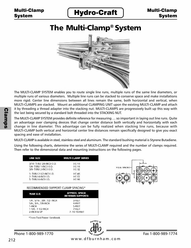
The MULTI-CLAMP SYSTEM enables you to route single line runs, multiple runs of the same line diameters, ormultiple runs of various diameters. Multiple line runs can be stacked to conserve space and make installationsmore rigid. Center line dimensions between all lines remain the same, both horizontal and vertical, whenMULTI-CLAMPS are stacked. Mount an additional CLAMPING UNIT upon the existing MULTI-CLAMP and attachit by threading a thread adapter into the stacking nut. MULTI-CLAMPS are progressively built up this way withthe last being secured by a standard bolt threaded into the STACKING NUT.
The MULTI-CLAMP SYSTEM provides definite reference for measuring ... so important in laying out line runs. Quitean advantage over clamping devices that change center distance both vertically and horizontally with eachchange in line diameter. This advantage can be fully realized when stacking line runs, because withMULTI-CLAMP both vertical and horizontal center line distances remain specifically designed to give you exactspacing and ease of installation.
MULTI-CLAMP is available in steel, stainless steel and aluminum. The standard bushing material is Styrene Butadiene.
Using the following charts, determine the series of MULTI-CLAMP required and the number of clamps required.Then refer to the dimensional data and mounting instructions on the following pages.

213
Cla
mp
s
w w w. d f b u r n h a m . c o mPhone 1-800-989-1770 Fax 1-800-989-1774
The Multi-Clamp® System
A Socket-head StackingNut, shown at A, is usedin combination with eitherB, a Thread Adapter, C, aSelf-tapping Adapter, or D,a Weld Adapter, to securethe lower Clamping Unitdirectly to a mountingsurface. The Stacking Nutis also used in combinationwith E, a Thread Adapter,lockwasher, and standardnut to attach the lowerClamping Unit through adrilled hole in mounting toa plate of 3/8 inch (or less)thickness.
After inserting JunctionAdapters or Split Bushingsand Lines into the lowerClamping Unit, the upperClamping Unit is attachedby positioning it over theLower Clamping Unit andplacing G, a standard boltand lockwasher, througheach mounting hole andthreading the bolt securelyinto its correspondingStacking Nut. Thiscompletes the assembly ofa basic MULTI-CLAMP
In bridge mountingbetween two columns, orwhen a MULTI-CLAMP issuspended from a column,either the E combinationor F, a standard bolt andlockwasher, can be used tosecure the Stacking Nut tothe lower Clamping Unit.H Mounting Adapters areplaced into appropriateholes, the lines or JunctionAdapters installed, theupper Clamping Unitattached, and thecomplete assembly thensecured by the MountingAdapters and standardbolts.
Hydro-CraftMulti-ClampSystem
Multi-ClampSystem
w w w. d f b u r n h a m . c o mPhone 1-800-989-1770 Fax 1-800-989-1774
214
Cla
mp
s
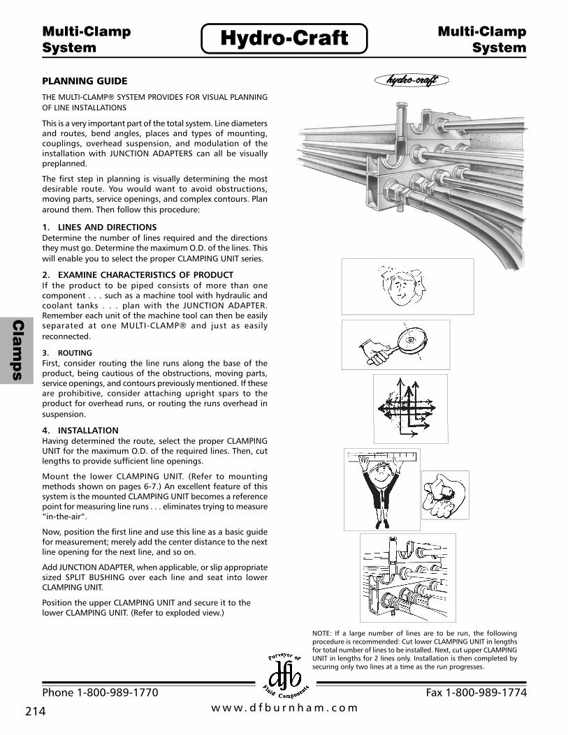
PLANNING GUIDE
THE MULTI-CLAMP® SYSTEM PROVIDES FOR VISUAL PLANNINGOF LINE INSTALLATIONS
This is a very important part of the total system. Line diametersand routes, bend angles, places and types of mounting,couplings, overhead suspension, and modulation of theinstallation with JUNCTION ADAPTERS can all be visuallypreplanned.
The first step in planning is visually determining the mostdesirable route. You would want to avoid obstructions,moving parts, service openings, and complex contours. Planaround them. Then follow this procedure:
1. LINES AND DIRECTIONSDetermine the number of lines required and the directionsthey must go. Determine the maximum O.D. of the lines. Thiswill enable you to select the proper CLAMPING UNIT series.
2. EXAMINE CHARACTERISTICS OF PRODUCTIf the product to be piped consists of more than onecomponent . . . such as a machine tool with hydraulic andcoolant tanks . . . plan with the JUNCTION ADAPTER.Remember each unit of the machine tool can then be easilyseparated at one MULTI-CLAMP® and just as easilyreconnected.
3. ROUTINGFirst, consider routing the line runs along the base of theproduct, being cautious of the obstructions, moving parts,service openings, and contours previously mentioned. If theseare prohibitive, consider attaching upright spars to theproduct for overhead runs, or routing the runs overhead insuspension.
4. INSTALLATIONHaving determined the route, select the proper CLAMPINGUNIT for the maximum O.D. of the required lines. Then, cutlengths to provide sufficient line openings.
Mount the lower CLAMPING UNIT. (Refer to mountingmethods shown on pages 6-7.) An excellent feature of thissystem is the mounted CLAMPING UNIT becomes a referencepoint for measuring line runs . . . eliminates trying to measure“in-the-air”.
Now, position the first line and use this line as a basic guidefor measurement; merely add the center distance to the nextline opening for the next line, and so on.
Add JUNCTION ADAPTER, when applicable, or slip appropriatesized SPLIT BUSHING over each line and seat into lowerCLAMPING UNIT.
Position the upper CLAMPING UNIT and secure it to thelower CLAMPING UNIT. (Refer to exploded view.)
Hydro-CraftMulti-ClampSystem
Multi-ClampSystem
NOTE: If a large number of lines are to be run, the followingprocedure is recommended: Cut lower CLAMPING UNIT in lengthsfor total number of lines to be installed. Next, cut upper CLAMPINGUNIT in lengths for 2 lines only. Installation is then completed bysecuring only two lines at a time as the run progresses.
fi

215
Cla
mp
s
w w w. d f b u r n h a m . c o mPhone 1-800-989-1770 Fax 1-800-989-1774
Hydro-CraftMulti-ClampSystem
Multi-ClampSystem
SUGGESTED MOUNTING METHODS
Actual installation of a line run, using the MULTI-CLAMP SYSTEM, begins with the mounting of the lower Clampingunit. Various methods are available to the installer for securing the lower Clamping Unit to the machinebase, pillar, upright spar, mounting plate, etc.
WELD ADAPTER
1. Insert WeldAdapter intomounting hole oflower ClampingUnit.
Secure Weld Adapterto lower ClampingUnit with sockethead stacking nut(finger tight). RepeatSteps 1 and 2 foreach hole ofClamping Unit.
Weld Adapterattached to lowerclamping unitprovides the basis ofthis method.
2. Position assembledunit ontomounting surface.
3. Weld base of eachWeld Adapter tomounting surface.
4. Tighten allStacking Nutssecurely andproceed withremainder ofinstallation.
THREAD ADAPTERFOR TAPPED HOLE
1. Using a scale, or theClamping Unit itself,measure and marklocation onmounting surfacefor each mountinghole on the lowerClamping Unit.Note that allmounting holes arespaced at evenincrements.
2. Drill appropriate sizehole for theparticular MULTI-CLAMP series beinginstalled.
3. Using tapping tool,tap each hole withappropriate sizethread for seriesbeing installed.
4. Assemble requirednumber of StackingNuts and ThreadAdapters for eachmounting hole.
5. Position lowerClamping Unit overtapped holes andthread assembledThread Adapter-Stacking Nut intoeach until fingertight.
6. Tighten all StackingNuts securely andproceed withremainder ofinstallation.
w w w. d f b u r n h a m . c o mPhone 1-800-989-1770 Fax 1-800-989-1774
216
Cla
mp
s
Hydro-CraftMulti-ClampSystem
Multi-ClampSystem
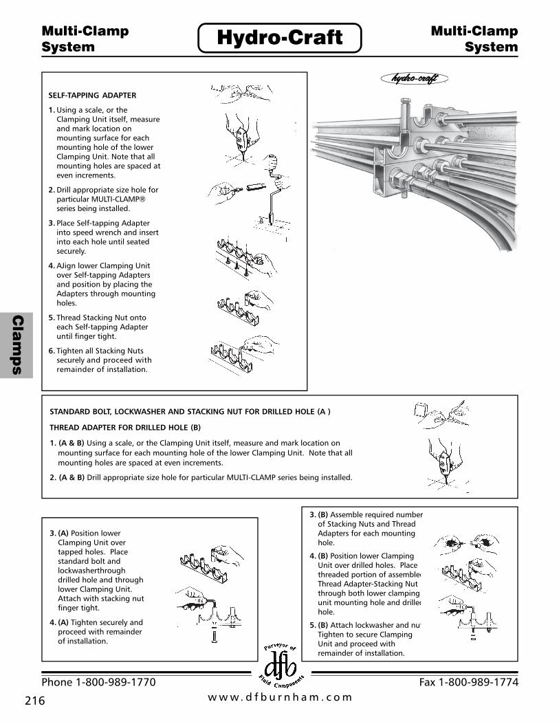
SELF-TAPPING ADAPTER
1. Using a scale, or theClamping Unit itself, measureand mark location onmounting surface for eachmounting hole of the lowerClamping Unit. Note that allmounting holes are spaced ateven increments.
2. Drill appropriate size hole forparticular MULTI-CLAMP®series being installed.
3. Place Self-tapping Adapterinto speed wrench and insertinto each hole until seatedsecurely.
4. AJign lower Clamping Unitover Self-tapping Adaptersand position by placing theAdapters through mountingholes.
5. Thread Stacking Nut ontoeach Self-tapping Adapteruntil finger tight.
6. Tighten all Stacking Nutssecurely and proceed withremainder of installation.
STANDARD BOLT, LOCKWASHER AND STACKING NUT FOR DRILLED HOLE (A )
THREAD ADAPTER FOR DRILLED HOLE (B)
1. (A & B) Using a scale, or the Clamping Unit itself, measure and mark location onmounting surface for each mounting hole of the lower Clamping Unit. Note that allmounting holes are spaced at even increments.
2. (A & B) Drill appropriate size hole for particular MULTI-CLAMP series being installed.
3. (A) Position lowerClamping Unit overtapped holes. Placestandard bolt andlockwasherthroughdrilled hole and throughlower Clamping Unit.Attach with stacking nutfinger tight.
4. (A) Tighten securely andproceed with remainderof installation.
3. (B) Assemble required numberof Stacking Nuts and ThreadAdapters for each mountinghole.
4. (B) Position lower ClampingUnit over drilled holes. Placethreaded portion of assembledThread Adapter-Stacking Nutthrough both lower clampingunit mounting hole and drilledhole.
5. (B) Attach lockwasher and nut.Tighten to secure ClampingUnit and proceed withremainder of installation.
fi

217
Cla
mp
s
w w w. d f b u r n h a m . c o mPhone 1-800-989-1770 Fax 1-800-989-1774
Hydro-CraftJunctionAdapters
JunctionAdapters
Hydro-Craft®
Junction Adapters - A Fitting Solution
The Hydro-Craft line of patented junction adapters are designed toeliminate traditional union problems. They are engineered to fit securelyinto the MULTI-CLAMP® and STRUT-ADAPTER® systems. Offered in a widerange of standard sizes in JIC, NPT SAE, and O-Ring Face Seal style, theyare manufactured of 12L14 Leadloy and finished in a zinc plating.
They area critical element in both junction clamping systems, and areavailable in sizes as listed in the chart below. (See page 13 for dimensions).
Call for information and quantity requirements on special junction adaptersfor Strut-Adapter and MULTI-CLAMP such as inverted flare, Japanese andBSP sizes. Fittings are available in a wide range of materials also, includingstainless steel and brass.
UNION PROBLEMS THAT HYDRO-CRAFT SYSTEMS HELP PREVENT
When unions are in suspensionand improperly secured, they canvibrate and cold-work, causingleaks.
A bulkhead fitting must beinserted into a drilled plate andlocked in position from each side.There must be clearance in theplate to locate the fitting, and ifthe locknuts aren’t 100% secure,vibration will cause the assemblyto work loose, causing leaks.
With a pipe-tapped junctionblock, you have an additionalconnection point in your system.Another joint that can leak.

w w w. d f b u r n h a m . c o mPhone 1-800-989-1770 Fax 1-800-989-1774
218
Cla
mp
s
Hydro-CraftMulti-ClampBulkhead Spacer
Multi-ClampBulkhead Spacer
The MULTI-CLAMP® Bulkhead Spacer is designed to allowadapters for the 2" HC-16 Series MULTI-CLAMP to be appliedto the 3" HC-32 Series MULTI-CLAMP The Bulkhead is arugged molded thermoplastic elastomer that can withstandthe effects of most oils, chemicals, and cleaning compoundsfrom -48°F to 275°F
The features and benefits of the MULTI-CLAMP BulkheadSpacer:
All of the HC-16 Series Junction Adapters can be used inthe HC-32 Series MULTI-CLAMPS
The need for bulky and heavy adapters and bushingreducers is eliminated
The cost to apply the junction adapters is reduced toapproximately 1/6 of the previous cost to do the samejob
Metal to metal contact is replaced by an elastomer thatis actually a cushion that will reduce noise whileabsorbing shock and vibration
A Living Hinge allows the MULTI-CLAMP Bulkhead Spacerto be spread apart for quick and easy installation
Now the junction adapters can be utilized in the HC-32 SeriesClamps easier, quicker, at much less cost, and the clampingsystem is improved considerably. The elimination of thebushing reducers means less potential leak problems andthe cushion effect will benefit any industrial clamping system.
How To OrderSpecify the Bulkhead Spacer by part number HC-32-BS-16
Multi-Clamp®
Bulkhead Spacerfi
1.50
1.20
.58 .06 R
.10 R
.70.42
.25 .221.752.122.25
219
Cla
mp
s
w w w. d f b u r n h a m . c o mPhone 1-800-989-1770 Fax 1-800-989-1774
Hydro-CraftMulti-ClampSystem
Multi-ClampSystem
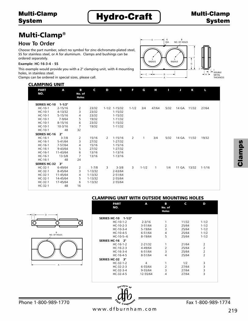
Multi-Clamp®
How To OrderChoose the part number, select no symbol for zinc-dichromate-plated steel,SS for stainless steel, or A for aluminum. Clamps and bushings can beordered separately.
Example: HC-16-3-4 - SS
This example would provide you with a 2" clamping unit, with 4 mountingholes, in stainless steel.Clamps can be ordered in special sizes, please call.
CLAMPING UNIT
CLAMPING UNIT WITH OUTSIDE MOUNTING HOLES

w w w. d f b u r n h a m . c o mPhone 1-800-989-1770 Fax 1-800-989-1774
220
Cla
mp
s
Hydro-CraftMulti-ClampSystem
Multi-ClampSystem
SINGLE CLAMPING UNIT WITH OUTSIDE MOUNTING HOLES
DOUBLE CLAMPING UNIT
SPLIT BUSHING FOR TUBE AND PIPE APPLICATIONS
How To Orderselect by part number. Silicone bushings areavailable for service up to 500°. Call forpricing and quantity requirements.
All dimensions are approximate in inches

221
Cla
mp
s
w w w. d f b u r n h a m . c o mPhone 1-800-989-1770 Fax 1-800-989-1774
Hydro-CraftMulti-ClampSystem
Multi-ClampSystem
Multi-Clamp® CLAMPING UNIT
SPLIT BUSHING FOR PIPE APPLICATIONS

w w w. d f b u r n h a m . c o mPhone 1-800-989-1770 Fax 1-800-989-1774
222
Cla
mp
s
Hydro-CraftMulti-ClampSystem
Multi-ClampSystem
All dimensions are approximate in inches

223
Cla
mp
s
w w w. d f b u r n h a m . c o mPhone 1-800-989-1770 Fax 1-800-989-1774
Hydro-CraftMulti-ClampSystem
Multi-ClampSystem
Multi-Clamp®
How To Orderselect by part number. *Add SS to endof part number for stainless steel.
w w w. d f b u r n h a m . c o mPhone 1-800-989-1770 Fax 1-800-989-1774
224
Cla
mp
s
Hydro-CraftStrut-Adapter
Strut-Adapter
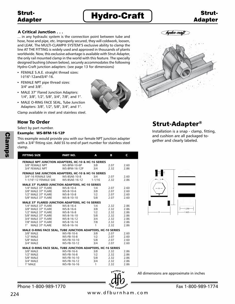
A Critical Junction . . .... in any hydraulic system is the connection point between tube andhose, hose and pipe, etc. Improperly secured, they will coldwork, loosen,and LEAK. The MULTI-CLAMP® SYSTEM’S exclusive ability to clamp theline AT THE FITTING is widely used and approved in thousands of plantsworldwide. Now, this exclusive advantage is available with Strut-Adapter,the only rail mounted clamp in the world with this feature. The speciallydesigned bushing (shown below), securely accommodates the followingHydro-Craft junction adapters: (see page 13 for dimensions)
• FEMALE S.A.E. straight thread sizes:l-l/16"-12and3/4"-16.
• FEMALE NPT pipe thread sizes:3/4" and 3/8".
• MALE 37° Flared Junction Adapters:1/4", 3/8", 1/2", 5/8", 3/4", 7/8", and 1".
• MALE O-RING FACE SEAL, Tube JunctionAdapters: 3/8", 1/2", 5/8", 3/4", and 1".
Clamp available in steel and stainless steel.
How To OrderSelect by part number.Example: WS-BFM-16-12P
This example would provide you with our female NPT junction adapterwith a 3/4" fitting size. Add SS to end of part number for stainless steelclamp.
All dimensions are approximate in inches
Strut-Adapter®
Installation is a snap - clamp, fitting,and cushion are all packaged to-gether and clearly labeled.
225
Cla
mp
s
w w w. d f b u r n h a m . c o mPhone 1-800-989-1770 Fax 1-800-989-1774
Hydro-CraftWalker-Strut
Walker-Strut
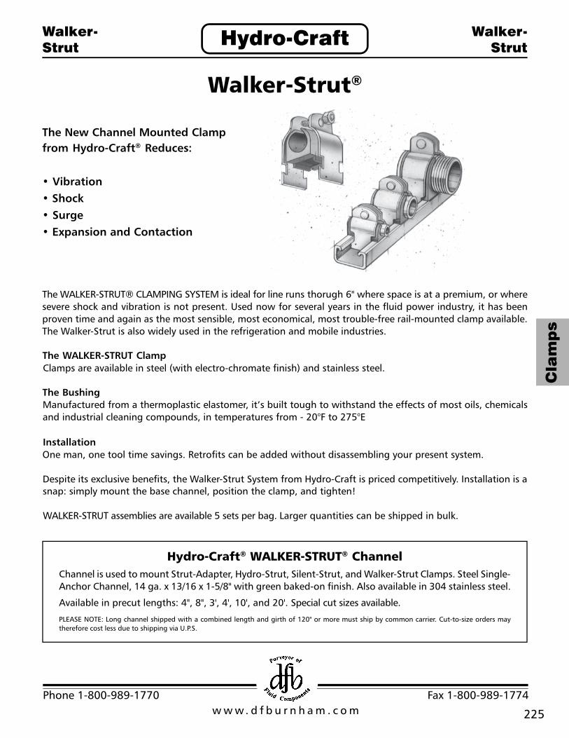
The WALKER-STRUT® CLAMPING SYSTEM is ideal for line runs thorugh 6" where space is at a premium, or wheresevere shock and vibration is not present. Used now for several years in the fluid power industry, it has beenproven time and again as the most sensible, most economical, most trouble-free rail-mounted clamp available.The Walker-Strut is also widely used in the refrigeration and mobile industries.
The WALKER-STRUT ClampClamps are available in steel (with electro-chromate finish) and stainless steel.
The BushingManufactured from a thermoplastic elastomer, it’s built tough to withstand the effects of most oils, chemicalsand industrial cleaning compounds, in temperatures from - 20°F to 275°E
InstallationOne man, one tool time savings. Retrofits can be added without disassembling your present system.
Despite its exclusive benefits, the Walker-Strut System from Hydro-Craft is priced competitively. Installation is asnap: simply mount the base channel, position the clamp, and tighten!
WALKER-STRUT assemblies are available 5 sets per bag. Larger quantities can be shipped in bulk.
Hydro-Craft® WALKER-STRUT® ChannelChannel is used to mount Strut-Adapter, Hydro-Strut, Silent-Strut, and Walker-Strut Clamps. Steel Single-Anchor Channel, 14 ga. x 13/16 x 1-5/8" with green baked-on finish. Also available in 304 stainless steel.
Available in precut lengths: 4", 8", 3', 4', 10', and 20'. Special cut sizes available.
PLEASE NOTE: Long channel shipped with a combined length and girth of 120" or more must ship by common carrier. Cut-to-size orders maytherefore cost less due to shipping via U.P.S.
Walker-Strut®
The New Channel Mounted Clampfrom Hydro-Craft® Reduces:
• Vibration• Shock• Surge• Expansion and Contaction

w w w. d f b u r n h a m . c o mPhone 1-800-989-1770 Fax 1-800-989-1774
226
Cla
mp
s
Hydro-CraftWalker-Strut
Walker-Strut
How To OrderSimply choose the clamp size, select no symbol for zinc-dichromate-plated steel
or SS for stainless steel, and the appropriate bushing size.
Example: WS-06-P - SS
This example would provide you with a stainless steel clamp, and a cushion for a 3/8” pipe.

227
Cla
mp
s
w w w. d f b u r n h a m . c o mPhone 1-800-989-1770 Fax 1-800-989-1774
Hydro-CraftHydro-StrutClamping System
Hydro-StrutClamping System
The Hydro-Strut clamping system is designed for hydraulic,pneumatic, electrical, and fuel line applications, where itretains, guides, protects, and spaces line runs uniformly.This design can easily maintain equal centers, even whenthe line size varies. Lines are rigid, have a neat appearance,and install easily through channel mounting.
Independent testing shows the Hydro-Strut clampingsystem, using Styrene Butadiene Rubber (SBR) bushings,to be 80 percent more efficient at reducing noise thanconventional cushion clamping systems. The SBR bushing,which provides the cushion for the reduced line noise, iscompression molded, and selected for its excellentcompatibility with industrial solvents, fuels, and hydraulicfluids. The clamp is available in either stainless orzinc-dichromate-plated steel.
Available standard sizes for tube, hose and pipe range from1/4-inch through 2-inch. Special sizes are available, pleasecontact the factory for more information.
How To OrderSimply choose the clamp size, select no symbol forzinc- dichromate-plated steel or SS for stainless steel, and theappropriate bushing size. Clamps and bushings can be orderedseparately.Example: HCS-32-M - SS - RSG-3Z-IOThis example would provide you with our larger, stainlesssteel clamp, and a bushing for 5/8" tube.
Hydro-Strut® Clamping System
The New Hydro-Strut Clamping System is the mosteffective clamp available - greatly reducing noise dueto line shock and vibration!
Reduces line noise by as muchas 80%
Available in wide range of line sizes from 1/4" to2"
Easy installation through channel mounting
High-quality materials of construction

w w w. d f b u r n h a m . c o mPhone 1-800-989-1770 Fax 1-800-989-1774
228
Cla
mp
s
Hydro-CraftSilent-StrutClamping System
Silent-StrutClamping System
The Silent-Strut clamping system is excellent for use inrefrigeration, HVAC and electrical applications, but is alsoeffective on hydraulic, pneumatic and fuel line applications.In addition to its low cost, it offers excellent noise reductiondue to the materials of construction and design of the channelmounting system. This channel mounting makes for a quickand easy installation. The superior design will maintain equalcenters, even when the line size varies. Lines remain rigidand have a neat appearance.
The clamp is made from Zytel® (glass-filled nylon) that is veryresistant to corrosion, and much lower in cost than stainlesssteel. Two clamp sizes are available. All the bushings are madefrom Styrene Butadiene Rubber (SBR). The bushing is securedin the clamp using stainless steel nuts and bolts. The SBRbushing is compression molded, selected for its compatibilitywith most oils, chemicals, and cleaning compounds, andprovides the cushion for the noise reduction.
Available standard sizes for tube and pipe range from1/4-inch through 2-inch. Please contact the factory for moreinformation.
How To OrderSimply choose the clamp size and the appropriate bushing size.Clamps and bushings are ordered separately.
Example: HC-SS-16 - G-16-10
This example would provide you with our smaller Zytel® glass-fillednylon clamp and a bushing for 5/8" tube.
Silent-Strut® Clamping System
Easy channel mounting installation
Wide range of line sizes from 1/4" to 2"
High-quality materials of construction
Greatly reduces line noise
All dimensions are approximate in inches

229
Cla
mp
s
w w w. d f b u r n h a m . c o mPhone 1-800-989-1770 Fax 1-800-989-1774
Hydro-CraftEcono-IsolatorClamping System
Econo-IsolatorClamping System
Econo-Isolator® Clamping System
Inexpensive Cushions To Fit Standard PipeStraps
The Econo-lsolator clamping system offers alow-cost, high-quality solution for use inplumbing, mechanical, and HVAC/Rapplications.
Easy mounting using readily-availablebrackets
Made from high-quality Styrene ButadieneRubber (SBR)
The Econo-lsolator is the low-cost answer for your clampingneeds. It not only meets the requirements for plumbing,mechanical, and HVAC/R applications, but performs well inhydraulic, pneumatic, fuel line, and electrical applications.
The Econo-lsolator, using standard pipe straps that arereadily available, retains, guides, protects and spaces lineruns uniformly. Lines are rigid, have a neat appearance, andinstall easily. The bushing is made from Sty-rene ButadieneRubber. It is compression molded and selected for itsexcellent compatibility with industrial solvents, fuels,hydraulic fluids, other liquids and gases.
How To OrderSimply choose the bushing number and appropriate strapnumber that corresponds to the tube or pipe size you need.Bushings and pipe straps are ordered separately.
Example: EI-10-12 EIM-10
This example would provide you with the correct bushing andstrap to fit a 3/4" tube.
All dimensions are approximate in inches

w w w. d f b u r n h a m . c o mPhone 1-800-989-1770 Fax 1-800-989-1774
Cla
mp
s
230
Hydro-CraftEnd Covers End Covers
End CoversHydro-Craft® end covers for replacement orretrofit are available in 12- 14- and 18-inchdiameters. Available in steel and stainlesssteel. Steel end covers are zinc plated forcorrosion protection. All end covers areavailable with optional drain. All have aunique formed on Buna-N lip seal which hasexcellent resistance to cutting and abrasion,and is compatible with all standardhydraulic fluids. Replacement sea Is, ifrequired, are readily available from stock.
The end cover is attached to the reservoirby the unique Hydro-Craft® baffle adapter.The design of the HC-BA-10 allows it to beattached to the baffle with press pins orstandard bolts, assuring a tight, shockproofinstallation, and eliminating the need forwelding and subsequent weld splatter,warping and stressing of the baffle. TheHydro-Craft® baffle adapter is also availablein type 304 stainless steel.
The Hydro-Craft® self aligning cover bar isavailable for 12- and 14-inch end covers.Installed by placing a bolt through the endcover and turning a few threads into thecover bar, it can then be angled throughthe reservoir access hole. Allowing the coverbar to rest on the bottom of the reservoir,it will automatically align itself to the properheight to be torqued firmly into place. Thisdurable self aligning cover bar is fabricatedfrom 3/8-inch hot rolled, pickled and oiledsteel plate. More than ample torque can beapplied to insure a perfect seal on the res-ervoir end cover.
Self Aligning Cover Bar
231
Cla
mp
s
w w w. d f b u r n h a m . c o mPhone 1-800-989-1770 Fax 1-800-989-1774
Hydro-CraftS.A.E. Adapters S.A.E. Adapters
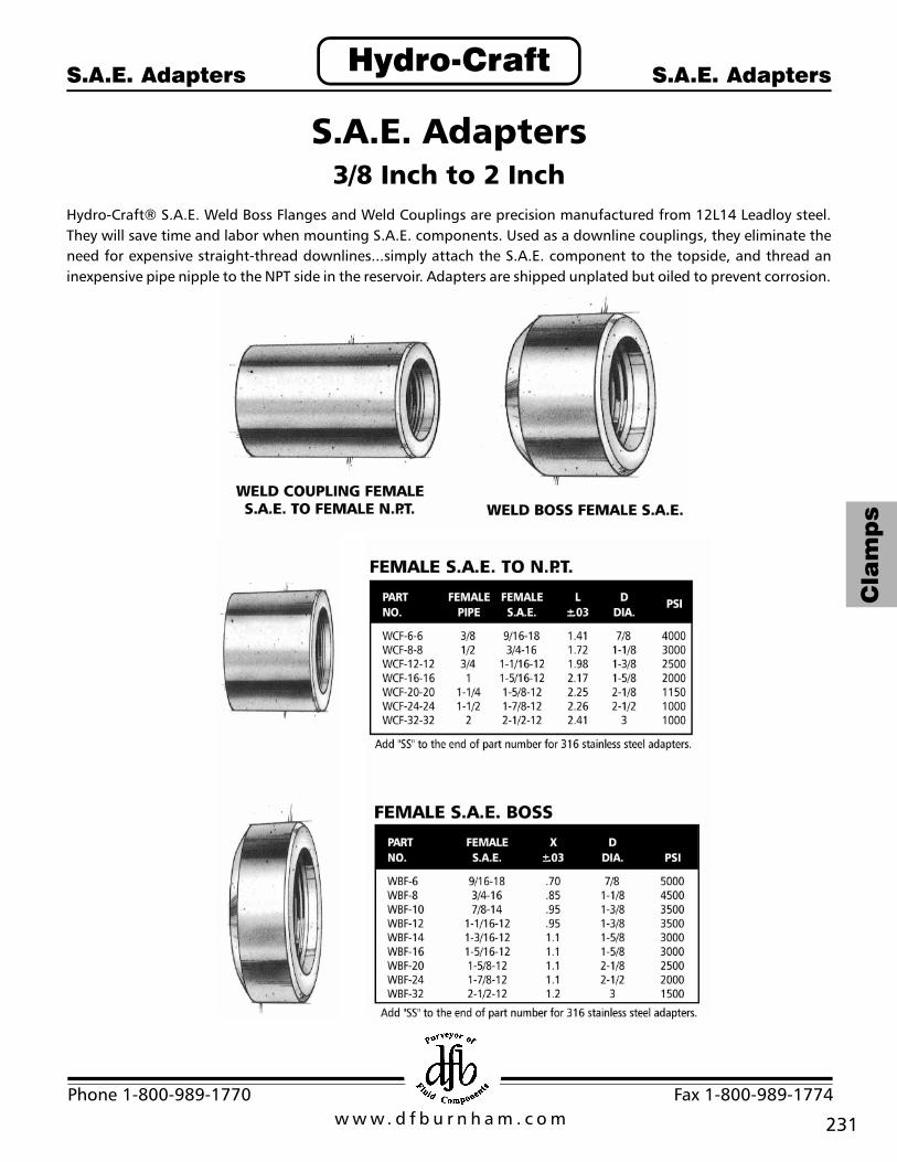
S.A.E. Adapters3/8 Inch to 2 Inch
Hydro-Craft® S.A.E. Weld Boss Flanges and Weld Couplings are precision manufactured from 12L14 Leadloy steel.They will save time and labor when mounting S.A.E. components. Used as a downline couplings, they eliminate theneed for expensive straight-thread downlines...simply attach the S.A.E. component to the topside, and thread aninexpensive pipe nipple to the NPT side in the reservoir. Adapters are shipped unplated but oiled to prevent corrosion.

w w w. d f b u r n h a m . c o mPhone 1-800-989-1770 Fax 1-800-989-1774
Cla
mp
s
232
Hydro-CraftOil LevelSight Plugs
SightLevel Gauge
Oil Level Sight Plugs
Sight Level Gauge*
HYDRO-CRAFT® SIGHT PLUGS ARE DESIGNED FOR QUICK VISUALINSPECTION OF LIQUID LEVELHC-SP Series Plugs use a transparent window with synthetic rubberseal. Body is of zinc plated steel, reflecting surface behind glass isstainless steel.
• Eliminate the need for dipsticks• Presence of liquid is clearly shown in window• Reflecting surface behind glass provides excellent visibility - even
in dark locations• Compatible with most fluids, including diesel fuel and phosphate
esters
PART NUMBER HSG-55The Hydro-Craft® Standard Sight Level Gauge is available only with temperature indicator.Complete with neoprene gaskets and attaching bolts - ready for immediate installation.
• Can be installed from either outside or inside reservoir unit. Requires onlytow mounting holes
• Sturdy low profile outer case• All external metal parts are plated• Extra large sight area, nonbreakable 2X magnifier• Thermometer standard with readings in centigrade and Fahrenheit• Will withstand temperatures to 225oF
• Available in stainless steel
* Cannot be used for pressurized applications. Sight Levelgauges are not designed for pressure applications.

233
Cla
mp
s
w w w. d f b u r n h a m . c o mPhone 1-800-989-1770 Fax 1-800-989-1774
Hydro-CraftSightLevel Gauge
SightLevel Gauge
HSG-66 SERIESHydro-Craft® fluid sight level gauges are available in 3- 5- and 10-inch sizes, with orwithout a dial type thermometer.
• Rugged construction• Plated steel shell and end blocks• Durable Lexan tube will not discolor• Pyrex glass tube available at no additional cost• Easy to read high visibility design• Viton O-Ring tube seals• Unique, easy mounting nylon seals• Easy to read, precision dial type thermometer• Will withstand temperatures from 0o-500oF (Pyrex), 0o-250oF (Lexan)
Add PL to end of part number for Pyrex, Lexan is standard.
Sight level gauges are not designed for pressure applications.
Sight Level Gauge

w w w. d f b u r n h a m . c o mPhone 1-800-989-1770 Fax 1-800-989-1774
Cla
mp
s
234
Hydro-CraftFiller BreatherAssembly Kit
Filler BreatherAssembly Kit
Filler Breather Assembly Kit
Filler Breather with4” strainer
Filler Breather with optionalmetal filler screen and dipstick
All dimensions are approximate in inches
PART NO. HC-120• Nylon strainer with guard...stronger than
conventional materials. Will not corrode.Compatible with most fluids.
• Flange on strainer acts as gasket-no unnecessaryparts to lose
• 4” or 8” strainer available
• Displaces 192 gallons per minute (25 CFM)
• Available in 10 or 40 micron
• Nylon strainer with openings equivalent to 30mesh
• Plated cap with safety chain
• All parts included in one package-ready to install
• Locking provision available to accept standard3/8” padlock
• Pressurized breather availableAS Anti-Slosh FeatureB Black Powder Coated CapD 6” Dip StickL Stainless Steel Locking TabM 10 Micron Element
PB-3 3 P.S.I. Pressurized BreatherPB-5 5 P.S.I. Pressurized BreatherPB-10 10 P.S.I. Pressurized Breather
S-3 3” Stainless Steel StrainerS-4 4” Nylon Strainer
SS-8 8” Stainless Steel Strainer
Safety chainallows removalof cap for cleaningof filter element
Slots provide largeamount of air flow
Deep groovesprovide better grip
Reinforced bottomhelps eliminatepunch-out duringfilling

235
Cla
mp
s
w w w. d f b u r n h a m . c o mPhone 1-800-989-1770 Fax 1-800-989-1774
Hydro-CraftAir Breathers Air Breathers
Air BreathersBreather filters are a must forhydraulic systems requiring clean airpassing into the reservoir, ensuringlong life of system components.
When used as a crankcase ventilator,it helps to prolong the life of theengine oil and the oil filter.
Pressurized breather available.

w w w. d f b u r n h a m . c o mPhone 1-800-989-1770 Fax 1-800-989-1774
Cla
mp
s
236
Hydro-CraftHydro-Craft®
Magnetic FiltrationHydro-Craft®
Magnetic Filtration
Hydro-Craft® Magnetic FiltrationHydro-Craft® magnetic tank traps and plugs are designed to maintainhydraulic systems by picking up ferrous particles that can clog ordinaryfilters. They are easily installed, and easily cleaned. The Hydro-Craft® ASseries Mag Trap features a wipeclean the ferrous particles from the unit.
The magnetic plug is available in 3/4” NPT.
Valuable pump and component protection is provided by theselow-cost, easily maintained units.
Improved magneticassembly withaluminum sheild foreasy wipe-cleanmaintenance andprotection ofmagnetics.
Add “AS” to end of part number when ordering with aluminum shieldExample: HC-MT-22AS
We suggest magnet assemblybe located within 1” ofreservoir bottom.
All dimensions are approximate in inches

237
Cla
mp
s
w w w. d f b u r n h a m . c o mPhone 1-800-989-1770 Fax 1-800-989-1774
Hydro-CraftReturnLine Filters
ReturnLine Filters
Return Line FiltersThe Hydro-Craft® range of spin-on filters are designed for return lineapplications and have a nominal retention of 10 micron as standard.Optional 25 micron canisters are available on request.
Three basic models which give interchangeability with most suppliers ofthis filter type are available. The filters are rated at 200 PSI (13 bar)working pressure and have flow rates of 15 to 50 GPM at 10 micron.
Hydro-Craft® spin-on filters are designed for use with mineral-based oilsas used in mobile, industrial, marine and agricultural applications.
Design Features• Full flow 10 micron• Optional 25 micron• 200 PSI working pressure• Interchangeable elements• Visual indicator• Disposable spin-on-canister• With 15 PSI bypass (1 bar)• Dual-thread design available on 50-series post allows use of
replacement canisters from Gresen, Pall, Lenz, MDI, Parker, UCC, etc.
All dimensions are approximate in inches
w w w. d f b u r n h a m . c o mPhone 1-800-989-1770 Fax 1-800-989-1774
Cla
mp
s
238
Hydro-CraftSeries HCRS30 and 50
Series HCRS30 and 50
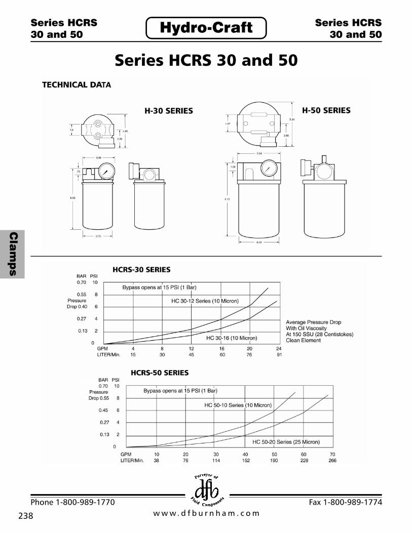
Series HCRS 30 and 50

239
Cla
mp
s
w w w. d f b u r n h a m . c o mPhone 1-800-989-1770 Fax 1-800-989-1774
Hydro-Craft® Magnetic Filtration
Hydro-CraftSuctionLine Filter
SuctionLine Filter
IN-TANK SUBMERGED TYPEHydro-Craft® offers a complete range of suction-line filters, for use with hydraulic fluids,lubricants, coolants, cutting oil, etc.
Features• Meets or excees all J.I.C. standards• 140 micron filtering• 100 mesh stainless steel screen, aluminum nut and end caps• Epoxied ends, hex connection• Gallon rating and micron size stamped on each filter• Extremely low pressure drops• Minimum sizes - maximum flow rates
Pressure drop through a cleanelement will not exceed 0.2 PSI(0.4-in. Hg) at rated flow of 150SSU viscosity fluid and 100mesh.
Hydro-Craft® recommendshand-tightening only tofacilitate servicing...wrenchtighten is not necessary.

w w w. d f b u r n h a m . c o mPhone 1-800-989-1770 Fax 1-800-989-1774
Cla
mp
s
240
Shock Mounts
Hydro-CraftShock Mounts Shock Mounts
PART NO. HC-SM-32The Hydro-Craft® Shock Mount is simple in design, engineered for rugged service and long life, having an innercylinder attached to the stud, which is insulated from the outer shell by a wall of mechanically bonded rubber. Theyhave an ample safety margin: Overloaded to destruction they will allow a drop of less than 1/2”.
• Cut down vibration• Helps subdue shock and noise• Easy to install• Inexpensive• No maintenance required• Allows Precision leveling
MOUNTING METHODSPlace plate through shock mount stud, lock both nuts into proper levelpositon. Weld adapters can be inserted into shock mount base and weldedinto position. Shock mounts can easily be removed by removing nuts fromweld pads.