the msx thermal design - the johns hopkins university ... · pdf filejohns hopkins apl...
TRANSCRIPT
THE MSX THERMAL DESIGN
T
The MSX Thermal Design
Julie A. Krein and Douglas S. Mehoke
his article presents the thermal design, analysis, and testing of the MidcourseSpace Experiment (MSX) satellite. The MSX spacecraft is planned for a 4-year life witha 5-year goal. Its thermal design is driven by its main sensor, the cryogen-cooled SpatialInfrared Imaging Telescope III, which requires a dewar shell temperature below 250 K.Other MSX science instruments are described as well. Thermal models developed topredict spacecraft and instrument temperatures for the range of expected orbitalattitudes are explored. The MSX thermal control scheme to maintain and monitoracceptable temperature levels is examined. Results of spacecraft-level thermal testingperformed at Goddard Space Flight Center are reported.
INTRODUCTIONThe Midcourse Space Experiment (MSX) satellite
is scheduled for launch aboard a Delta II rocket. Theprimary MSX instrument is the cryogen-cooled SpatialInfrared Imaging Telescope III (SPIRIT III). MSX is tofly in an 898-km circular orbit with a 99.2o inclination.It has a 4-year required lifetime with a 5-year goal anda 15-month minimal cryostat life. SPIRIT III has strin-gent thermal requirements that significantly affect thedesign of MSX. This article describes the spacecraftrequirements, the resulting thermal design, and thethermal testing done on the satellite.
SPACECRAFT REQUIREMENTSGiven the spacecraft orbit, the following primary
(1–4) and secondary (5–7) requirements for the ther-mal subsystem design must be met (see Ref. 1 for ad-ditional details):
JOHNS HOPKINS APL TECHNICAL DIGEST, VOLUME 17, NUMBER 1 (199
1. The spacecraft design must support two operationalmodes: parked, a waiting mode maintained innormal attitude with no science instrument opera-tion; and track, full science instrument operationmaintained in virtually any attitude for up to37 min.
2. All instruments and subsystems must be maintainedwithin specified operating temperature limits.
3. A 4-year spacecraft life with a 5-year goal and a15-month SPIRIT III sensor life must be provided.
4. The SPIRIT III sensor dewar shell must be main-tained at less than the 250 K (223°C) specificationtemperature (225 K goal).
5. The spacecraft design must accommodate about 20min of full spacecraft and instrument operation perorbit (transient or episodic design).
6. The spacecraft thermal design must recover from anyoperational event within 24 h. Full recovery includes
6) 49

J. A. KREIN AND D. S. MEHOKE
restabilization of all spacecraft temperatures and heatercurrents.
7. A thermally stable platform for mounting additionalsensors co-aligned to SPIRIT III must be provided.Mechanical distortion due to thermal gradients mustbe controlled to less than 0.03°.
SPACECRAFT OVERVIEWThe MSX spacecraft has three main parts: the in-
strument section at the top, the truss section in themiddle, and the electronics section at the bottom.These sections are thermally isolated from one another.Figure 1 shows the overall spacecraft configuration.The instrument section is the platform on which mostof the science sensors are mounted. These sensorsinclude the UVISI (ultraviolet and visible imagers andspectrographic imagers) and SBV (space-based visibleimagers), the optical bench, the beacon receiver anten-na, and the reference object ejectors. The truss sectionprovides a stable mounting structure for the instrumentsection as well as the mounting point for the SPIRITIII cryostat and telescope. The electronics sectionhouses the spacecraft and instrument support electron-ics and the solar array panels.
ORBITAL DEFINITION ANDSPACECRAFT ATTITUDE
Two very important factors affecting the MSX ther-mal design are its orbit and attitude. The lifetime andperformance requirements of the primary instrumentnecessitate strict control of direct sunlight on thespacecraft.
MSX is to operate in a high-altitude, circular, polarorbit with a precession rate of less than 0.04° per day.Over the 5-year mission goal, the Sun line/orbit planeangle will increase from 45° through 120°; significantly,that angle is never less than about 45°. This orbitallows the spacecraft to fly in a roughly Earth-orientedattitude while keeping direct sunlight out of the instru-ment apertures. Controlling the spacecraft’s attituderelative to the Sun is one requirement that shapes thewhole mission.
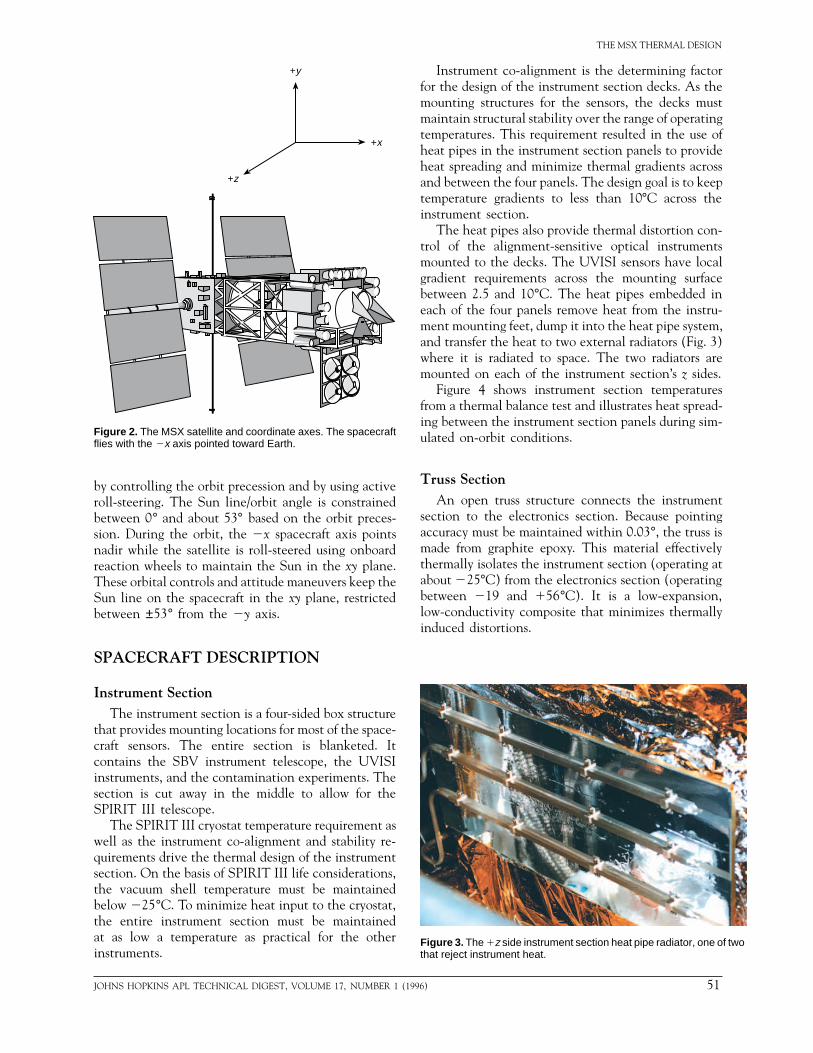
The MSX spacecraft and its coordinate axes areshown in Fig. 2. The x axis is parallel to the line of sightof the instruments. The z axes form a line parallel tothe drive axes for the solar array. The y axis completesa right-handed coordinate system. In this system, thespacecraft flies with the 2x axis pointed to Earth andthe 1x axis pointed to space.
Preferably, both from a thermal and power stand-point, the Sun will remain in the xy plane, constrainedbetween ±90° from the 2y axis. This orientation al-lows the solar panels to develop full power and providesa stable, cold environment for the SPIRIT III cryostat.
50 JOH
Normally, in an Earth-orientated orbit, one spacecraftaxis points nadir and one is fixed along the velocityvector. During one orbit, the Sun sweeps out a coneequal to the angle between the Sun line and the orbitnormal. As the orbit precesses, the cone varies from 0°in a dawn–dusk orbit to 90° in a noon–midnight orbit.Maintaining stable environments for the SPIRIT IIIcryostat and spacecraft radiators requires that the rangeof solar angles be minimized. MSX satisfies this need
Figure 1. The overall configuration of the Midcourse Space Experiment(MSX) spacecraft with the instrument section at the top, the truss sectionin the middle, and the electronics section at the bottom.
NS HOPKINS APL TECHNICAL DIGEST, VOLUME 17, NUMBER 1 (1996)
THE MSX THERMAL DESIGN
by controlling the orbit precession and by using activeroll-steering. The Sun line/orbit angle is constrainedbetween 0° and about 53° based on the orbit preces-sion. During the orbit, the 2x spacecraft axis pointsnadir while the satellite is roll-steered using onboardreaction wheels to maintain the Sun in the xy plane.These orbital controls and attitude maneuvers keep theSun line on the spacecraft in the xy plane, restrictedbetween ±53° from the 2y axis.
SPACECRAFT DESCRIPTION
Instrument SectionThe instrument section is a four-sided box structure
that provides mounting locations for most of the space-craft sensors. The entire section is blanketed. Itcontains the SBV instrument telescope, the UVISIinstruments, and the contamination experiments. Thesection is cut away in the middle to allow for theSPIRIT III telescope.
The SPIRIT III cryostat temperature requirement aswell as the instrument co-alignment and stability re-quirements drive the thermal design of the instrumentsection. On the basis of SPIRIT III life considerations,the vacuum shell temperature must be maintainedbelow 225°C. To minimize heat input to the cryostat,the entire instrument section must be maintainedat as low a temperature as practical for the otherinstruments.
Figure 2. The MSX satellite and coordinate axes. The spacecraftflies with the 2x axis pointed toward Earth.
+y
+x
+z
JOHNS HOPKINS APL TECHNICAL DIGEST, VOLUME 17, NUMBER 1 (19
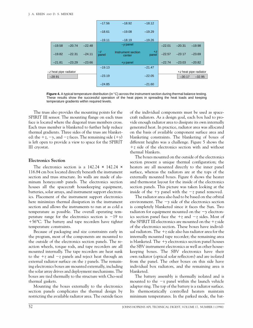
Instrument co-alignment is the determining factorfor the design of the instrument section decks. As themounting structures for the sensors, the decks mustmaintain structural stability over the range of operatingtemperatures. This requirement resulted in the use ofheat pipes in the instrument section panels to provideheat spreading and minimize thermal gradients acrossand between the four panels. The design goal is to keeptemperature gradients to less than 10°C across theinstrument section.
The heat pipes also provide thermal distortion con-trol of the alignment-sensitive optical instrumentsmounted to the decks. The UVISI sensors have localgradient requirements across the mounting surfacebetween 2.5 and 10°C. The heat pipes embedded ineach of the four panels remove heat from the instru-ment mounting feet, dump it into the heat pipe system,and transfer the heat to two external radiators (Fig. 3)where it is radiated to space. The two radiators aremounted on each of the instrument section’s z sides.
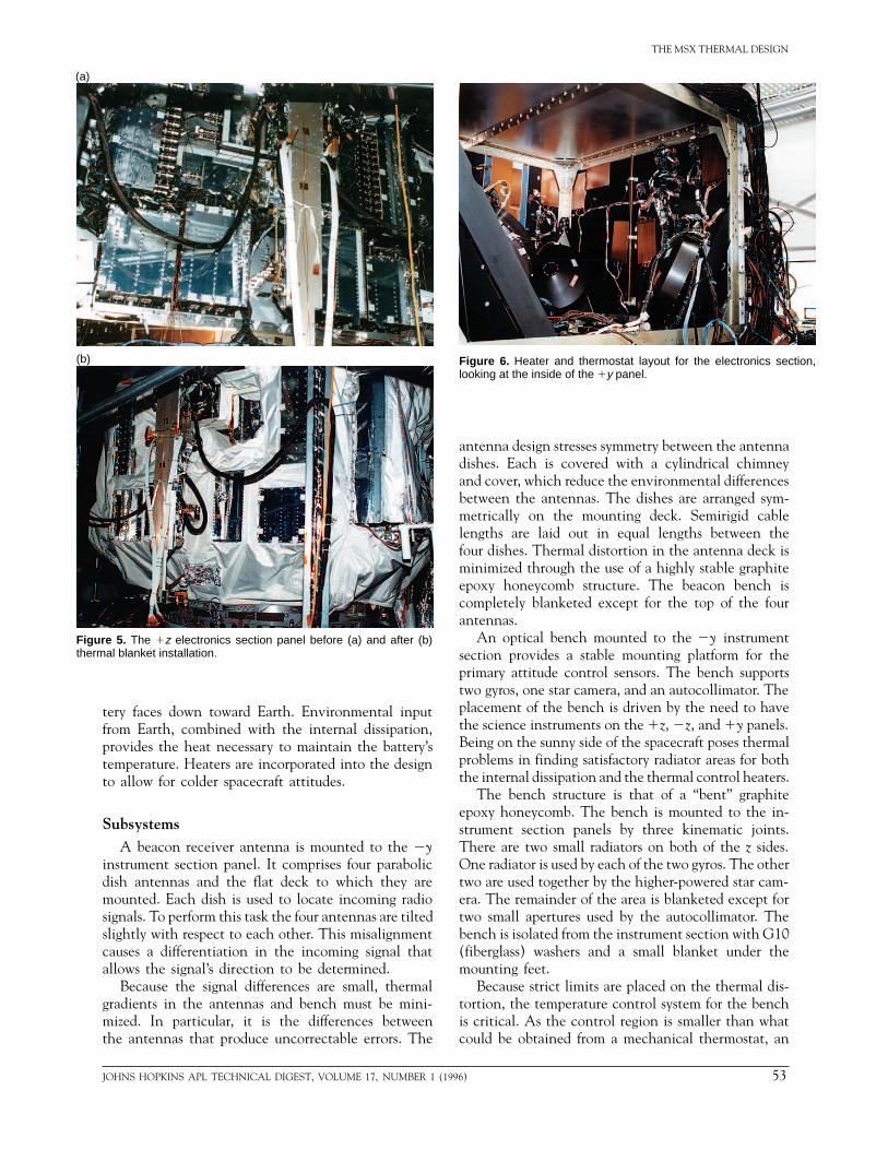
Figure 4 shows instrument section temperaturesfrom a thermal balance test and illustrates heat spread-ing between the instrument section panels during sim-ulated on-orbit conditions.
Truss SectionAn open truss structure connects the instrument
section to the electronics section. Because pointingaccuracy must be maintained within 0.03°, the truss ismade from graphite epoxy. This material effectivelythermally isolates the instrument section (operating atabout 225°C) from the electronics section (operatingbetween 219 and 156°C). It is a low-expansion,low-conductivity composite that minimizes thermallyinduced distortions.
Figure 3. The 1z side instrument section heat pipe radiator, one of twothat reject instrument heat.
96) 51
J. A. KREIN AND D. S. MEHOKE
–17.56 –18.92 –18.12
–18.61 –19.08 –19.29
–19.11 –18.19 –19.26
–19.13 –21.47
–23.19 –22.05
–24.85 –21.60
–19.58 –20.74 –22.48
–19.82 –22.31 –24.11
–21.81 –23.29 –23.66
–22.01 –20.31 –19.98
–22.57 –23 17 –23.69
–22.74 –23.03 –20.82
–y panel
+y panel
–zpanel
+zpanel
Instrument sectioncenter
+z heat pipe radiator–z heat pipe radiator
–30.17 –32.95–28.91
Figure 4. A typical temperature distribution (in °C) across the instrument section during thermal balance testing.These results show the successful operation of the heat pipes in spreading the heat loads and keepingtemperature gradients within required levels.
The truss also provides the mounting points for theSPIRIT III sensor. The mounting flange on each trussface is located where the diagonal truss members cross.Each truss member is blanketed to further help reducethermal gradients. Three sides of the truss are blanket-ed: the 1z, 2y, and 2z faces. The remaining side (1y)is left open to provide a view to space for the SPIRITIII cryostat.
Electronics SectionThe electronics section is a 142.24 × 142.24 ×
116.84 cm box located directly beneath the instrumentsection and truss structure. Its walls are made of alu-minum honeycomb panels. The electronics sectionhouses all the spacecraft housekeeping equipment,batteries, solar arrays, and instrument support electron-ics. Placement of the instrument support electronicshere minimizes thermal dissipation in the instrumentsection and allows the instruments to run at as cold atemperature as possible. The overall operating tem-perature range for the electronics section is 219 to156°C. The battery and tape recorders have tightertemperature constraints.
Because of packaging and size constraints early inthe program, most of the components are mounted tothe outside of the electronics section panels. The re-action wheels, torque rods, and tape recorders are allmounted internally. The tape recorders are heat sunkto the 1z and 2z panels and reject heat through anexternal radiator surface on the z panels. The remain-ing electronics boxes are mounted externally, includingthe solar array drives and deployment mechanisms. Theboxes are tied thermally to the structure with Cho-sealthermal gaskets.
Mounting the boxes externally to the electronicssection panels complicates the thermal design byrestricting the available radiator area. The outside faces
52 JOH
of the individual components must be used as space-craft radiators. As a design goal, each box had to pro-vide enough radiator area to dissipate its own internallygenerated heat. In practice, radiator area was allocatedon the basis of available component surface area andblanketing constraints. The blanketing of boxes ofdifferent heights was a challenge. Figure 5 shows the1z side of the electronics section with and withoutthermal blankets.
The boxes mounted on the outside of the electronicssection present a unique thermal configuration; theheaters are all mounted directly to the inner panelsurface, whereas the radiators are at the tops of theexternally mounted boxes. Figure 6 shows the heaterand thermostat layout for the inside of the electronicssection panels. This picture was taken looking at theinside of the 1y panel with the 2z panel removed.
The radiator area also had to be based on the orbitalenvironment. The 2y side of the electronics sectionis completely blanketed since it faces the Sun. Tworadiators for equipment mounted on the 2y electron-ics section panel face the 1z and 2z sides. Most ofthe SPIRIT III electronics are mounted on the 1z sideof the electronics section. These boxes have individ-ual radiators. The 1z side also has radiator area for theinternally mounted tape recorder; the remaining areais blanketed. The 1y electronics section panel housesthe SBV instrument electronics as well as other house-keeping boxes. The SBV electronics have theirown radiator (optical solar reflectors) and are isolatedfrom the panel. The other boxes on this side haveindividual box radiators, and the remaining area isblanketed.
The battery assembly is thermally isolated and ismounted to the 2x panel within the launch vehicleadapter ring. The top of the battery is a radiator surface.Its thermostatically controlled heaters maintainminimum temperatures. In the parked mode, the bat-
NS HOPKINS APL TECHNICAL DIGEST, VOLUME 17, NUMBER 1 (1996)
THE MSX THERMAL DESIGN
tery faces down toward Earth. Environmental inputfrom Earth, combined with the internal dissipation,provides the heat necessary to maintain the battery’stemperature. Heaters are incorporated into the designto allow for colder spacecraft attitudes.
SubsystemsA beacon receiver antenna is mounted to the 2y
instrument section panel. It comprises four parabolicdish antennas and the flat deck to which they aremounted. Each dish is used to locate incoming radiosignals. To perform this task the four antennas are tiltedslightly with respect to each other. This misalignmentcauses a differentiation in the incoming signal thatallows the signal’s direction to be determined.
Because the signal differences are small, thermalgradients in the antennas and bench must be mini-mized. In particular, it is the differences betweenthe antennas that produce uncorrectable errors. The
(a)
(b)
Figure 5. The 1z electronics section panel before (a) and after (b)thermal blanket installation.
JOHNS HOPKINS APL TECHNICAL DIGEST, VOLUME 17, NUMBER 1 (19
antenna design stresses symmetry between the antennadishes. Each is covered with a cylindrical chimneyand cover, which reduce the environmental differencesbetween the antennas. The dishes are arranged sym-metrically on the mounting deck. Semirigid cablelengths are laid out in equal lengths between thefour dishes. Thermal distortion in the antenna deck isminimized through the use of a highly stable graphiteepoxy honeycomb structure. The beacon bench iscompletely blanketed except for the top of the fourantennas.
An optical bench mounted to the 2y instrumentsection provides a stable mounting platform for theprimary attitude control sensors. The bench supportstwo gyros, one star camera, and an autocollimator. Theplacement of the bench is driven by the need to havethe science instruments on the 1z, 2z, and 1y panels.Being on the sunny side of the spacecraft poses thermalproblems in finding satisfactory radiator areas for boththe internal dissipation and the thermal control heaters.
The bench structure is that of a “bent” graphiteepoxy honeycomb. The bench is mounted to the in-strument section panels by three kinematic joints.There are two small radiators on both of the z sides.One radiator is used by each of the two gyros. The othertwo are used together by the higher-powered star cam-era. The remainder of the area is blanketed except fortwo small apertures used by the autocollimator. Thebench is isolated from the instrument section with G10(fiberglass) washers and a small blanket under themounting feet.
Because strict limits are placed on the thermal dis-tortion, the temperature control system for the benchis critical. As the control region is smaller than whatcould be obtained from a mechanical thermostat, an
Figure 6. Heater and thermostat layout for the electronics section,looking at the inside of the 1y panel.
96) 53
J. A. KREIN AND D. S. MEHOKE
electrical control system was planned. An on/off elec-tronic thermostat with a narrow dead band was chosenover a proportional system because of system complex-ities and the electromagnetic interference problemsassociated with a pulse-width–modulated device. Thefinal system uses remote temperature sensing to controlseven separate heater channels from one box. Two unitsare used to make the system fully redundant.
SCIENCE INSTRUMENTDESCRIPTIONS
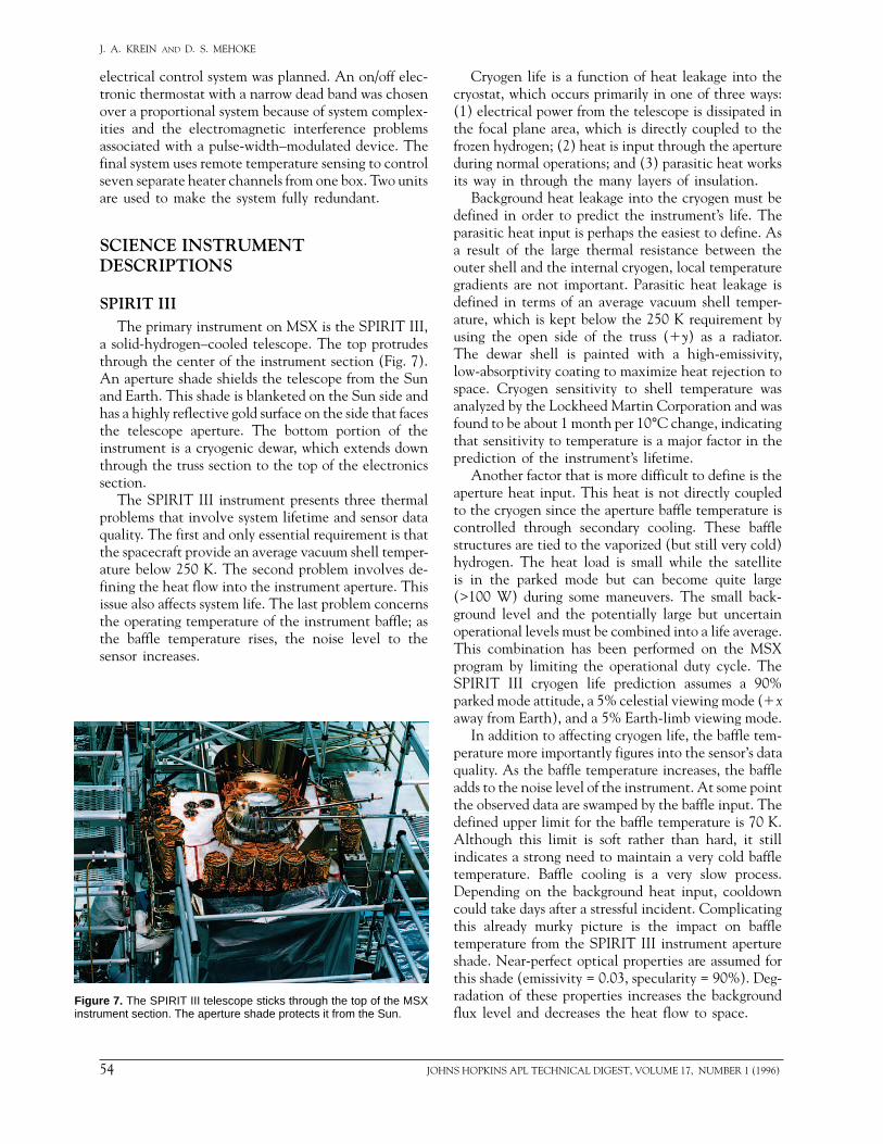
SPIRIT IIIThe primary instrument on MSX is the SPIRIT III,
a solid-hydrogen–cooled telescope. The top protrudesthrough the center of the instrument section (Fig. 7).An aperture shade shields the telescope from the Sunand Earth. This shade is blanketed on the Sun side andhas a highly reflective gold surface on the side that facesthe telescope aperture. The bottom portion of theinstrument is a cryogenic dewar, which extends downthrough the truss section to the top of the electronicssection.
The SPIRIT III instrument presents three thermalproblems that involve system lifetime and sensor dataquality. The first and only essential requirement is thatthe spacecraft provide an average vacuum shell temper-ature below 250 K. The second problem involves de-fining the heat flow into the instrument aperture. Thisissue also affects system life. The last problem concernsthe operating temperature of the instrument baffle; asthe baffle temperature rises, the noise level to thesensor increases.
Figure 7. The SPIRIT III telescope sticks through the top of the MSXinstrument section. The aperture shade protects it from the Sun.
54 JOH
Cryogen life is a function of heat leakage into thecryostat, which occurs primarily in one of three ways:(1) electrical power from the telescope is dissipated inthe focal plane area, which is directly coupled to thefrozen hydrogen; (2) heat is input through the apertureduring normal operations; and (3) parasitic heat worksits way in through the many layers of insulation.
Background heat leakage into the cryogen must bedefined in order to predict the instrument’s life. Theparasitic heat input is perhaps the easiest to define. Asa result of the large thermal resistance between theouter shell and the internal cryogen, local temperaturegradients are not important. Parasitic heat leakage isdefined in terms of an average vacuum shell temper-ature, which is kept below the 250 K requirement byusing the open side of the truss (1y) as a radiator.The dewar shell is painted with a high-emissivity,low-absorptivity coating to maximize heat rejection tospace. Cryogen sensitivity to shell temperature wasanalyzed by the Lockheed Martin Corporation and wasfound to be about 1 month per 10°C change, indicatingthat sensitivity to temperature is a major factor in theprediction of the instrument’s lifetime.
Another factor that is more difficult to define is theaperture heat input. This heat is not directly coupledto the cryogen since the aperture baffle temperature iscontrolled through secondary cooling. These bafflestructures are tied to the vaporized (but still very cold)hydrogen. The heat load is small while the satelliteis in the parked mode but can become quite large(>100 W) during some maneuvers. The small back-ground level and the potentially large but uncertainoperational levels must be combined into a life average.This combination has been performed on the MSXprogram by limiting the operational duty cycle. TheSPIRIT III cryogen life prediction assumes a 90%parked mode attitude, a 5% celestial viewing mode (1xaway from Earth), and a 5% Earth-limb viewing mode.
In addition to affecting cryogen life, the baffle tem-perature more importantly figures into the sensor’s dataquality. As the baffle temperature increases, the baffleadds to the noise level of the instrument. At some pointthe observed data are swamped by the baffle input. Thedefined upper limit for the baffle temperature is 70 K.Although this limit is soft rather than hard, it stillindicates a strong need to maintain a very cold baffletemperature. Baffle cooling is a very slow process.Depending on the background heat input, cooldowncould take days after a stressful incident. Complicatingthis already murky picture is the impact on baffletemperature from the SPIRIT III instrument apertureshade. Near-perfect optical properties are assumed forthis shade (emissivity = 0.03, specularity = 90%). Deg-radation of these properties increases the backgroundflux level and decreases the heat flow to space.
NS HOPKINS APL TECHNICAL DIGEST, VOLUME 17, NUMBER 1 (1996)

THE MSX THERMAL DESIGN
SBVThe SBV instrument is divided into two sections: the
telescope units mounted to the instrument section andthe electronics units mounted to the electronics section.Both units are thermally isolated from their respectivemounting panels and incorporate dedicated optical solarreflector radiators and heater control systems.
The telescope units are mounted to the 2z instru-ment section panel. The local radiator faces along the2z axis. The telescope sunshade design incorporates areclosable door, which has an opening mechanismlocated on the 2y side of the SBV instrument and isthermally controlled using the Sun’s input to thatsurface. The electronics support assembly is mountedto a honeycomb panel suspended by a truss supportstructure off the 1y electronics section panel.
UVISIThe UVISI comprises three electronics boxes
mounted to the electronics section and nine imagingtelescopes mounted to the instrument section. Thelatter include two ultraviolet imagers mounted to the1z instrument section panel, two visible imagersmounted to the 2z panel, and five spectrographic im-agers mounted to the 1y panel. Originally it was as-sumed that as these were low-power imagers, they couldradiate their own dissipated heat using localized radi-ators mounted on the sensors. As the design progressedit became clear that the requirement to minimize ther-mal distortion in the imagers would preclude thisoption. The need to remove the dissipated heat butmaintain control of thermally induced distortion led tothe heat pipe concept presently in use.
Three heat pipes (see discussion on Instrument Sec-tion) remove the local heat inputs and minimize ther-mal gradients in the structure. They are bonded to theexternal face of the honeycomb panels. The pipes inthe panels are level to allow ground testing but arearranged to pass near as many of the instruments’mounting feet as possible. Where feasible, the mount-ing foot insert and pipe cradle are machined in thesame piece.
The UVISI sunshades are thermally isolated fromthe telescope housings to reduce the net heat flow. Inthe parked mode, the sunshades will come within 45°of the Sun each orbit. As the orbit precesses, the solarimpingement angle will decrease. The early missionorbit will produce a varying, but small, positive averageheat input to the system. Later orbits will produce amore stable, but larger, heat loss.
Covers controlled by a one-shot opening mecha-nism protect each UVISI sunshade. The covers areopened after orbit is achieved. A special set of protec-tive heaters was needed to maintain the opening mech-anism within its operating temperature range. A small
JOHNS HOPKINS APL TECHNICAL DIGEST, VOLUME 17, NUMBER 1 (19
heater was therefore mounted near the door mecha-nism on each sunshade. The proper operation of theseheaters was verified by a separate thermal vacuum testof the sunshades.
The electronics boxes needed to support the UVISIinstrument are mounted to the 1y electronics sectionpanel. These boxes, which are treated as spacecraft sup-port electronics, are supported by the panel-mountedheater system. They incorporate radiator surfaces ontheir external faces and are internally designed to con-duct heat to the external faces.
Contamination ExperimentTo measure contamination, a number of sensors are
used to monitor particle type and density aroundthe instrument section. The sensors include a pres-sure sensor, a mass spectrometer, four temperature-controlled quartz crystal microbalances, and two lasers.As the sensors are low-powered and most efficientwhen powered continuously, their operation does notitself present a thermal problem. Rather, it is the typeof measurement that makes the situation potentiallydifficult. To get the necessary data, the spacecraft mustbe put in some attitude other than parked mode forextended periods of time. The impact of these othermaneuvers on the thermal and power systems is a func-tion of orbit position, Sun angle, satellite attitude, andinstrument operations before and after the maneuver.These variables are difficult to define in terms of aduration that can be analyzed; therefore, it is difficultto decide whether a proposed operation fits within theconstraints of the spacecraft resources.
THERMAL MODELINGThermal modeling and analysis of MSX were
performed using the TRASYS (Thermal RadiationAnalyzer System) and SINDA (Systems ImprovedNumerical Differencing Analyzer) thermal analyzerprograms. The former is a geometric modeler that com-putes the environmental heat loads and thermal radi-ation couplings for spacecraft surfaces in a given orbit.The resulting environmental fluxes and couplings fromTRASYS are input into a corresponding SINDAmodel, and the SINDA model is then run to givetemperature predictions. Separate, detailed thermalmodels exist for the instrument and electronics sec-tions, as well as for some subsystems (beacon receiver,optical bench, etc.). The models are biased for hot andcold temperature extremes. Surface property values andenvironmental parameters corresponding to the end ofthe mission are used in the analysis. The models wereused for test and flight temperature predictions.
Spacecraft modeling of the SPIRIT III sensor isrestricted to the calculation of the vacuum shell
96) 55
J. A. KREIN AND D. S. MEHOKE
temperature. All internal thermal modeling for thissensor is done by the Utah State University SpaceDynamics Laboratory. The boundary conditions assumea vacuum shell temperature and an aperture heat load.The thermal insulation in the cryostat is large enoughto allow the vacuum shell to be modeled as an adiabaticsurface. Calculation of the aperture heat load was doneby General Research Corporation (GRC) under con-tract to APL. GRC developed an algorithm that takesspecific orbits and attitude maneuvers and calculatesthe heat input to the SPIRIT III aperture. The algo-rithm includes direct and reflected energy inputs fromthe Sun, Earth, and Moon. Also included is directradiation from the aperture shade.
Several aspects of the thermal modeling effort onMSX separate it from typical spacecraft analyses. Theprimary atypical characteristic of the spacecraft is itsability to change attitudes, but more importantly, nei-ther a typical attitude nor even a range of attitudes isrequired.
To maximize available resources, operational limitsare generally confined to two categories. The first in-volves repeated orbital operation. A 20% duty cyclewas taken as a design goal. This duty cycle doubles thedesign operation of the SPIRIT III sensor and generallyallows unconstrained mission planning. A further clar-ification of this limit involves the battery depth ofdischarge. Operations that require the depth ofdischarge to exceed 40% should not be regularly sched-uled. Other factors contributing to this duty cyclelimitation are battery temperature, tape recorder tem-perature, and baffle temperature.
The second category involves high-priority one-at-a-time operations. These scenarios are essentially the sameas a target mode. The spacecraft goes into a preparationmode that lasts several orbits. Then the event takesplace, followed by several recuperative orbits. A longeroperation can be planned this way, but the overall dutycycle is reduced because event duration and recoverytime do not scale linearly (a 20-min operation once perorbit is not analogous to a 40-min operation every otherorbit). An upper bound for this type of operation is givenby the target mode timeline of about 40 min.
An issue related to the variable mission profileis power dissipation. The MSX parked mode is low-powered. An operation can result in an increase to thatpower of over 1000 W. The size and location of thepower increase depend on the type of mission selected.The thermal design provides some flexibility throughthe heater system. As power is dissipated in a particularsubsystem, less power is required by the heaters. Theheaters and radiator area are designed so that, at thefull 20% operation, the heaters draw virtually no power.
For analytical purposes, an operational attitude hadto be defined during data-taking events. Two such at-titudes were chosen—the parked mode and the
56 JOH
Sun-fixed mode. During operation in the parked mode,the power dissipations were changed to reflect theoperational values, but the attitude remained un-changed. This resulted in a benign hot or cold case. Allpredictions were expected to maintain the requiredmargin. During repeated operation in the Sun-fixedmode, the same side of the spacecraft would always beturned toward the Sun. This attitude produced worst-case hot and cold predictions. Such predictions may nothave the full margin typically required for a design case.For most components the temperatures of the worst-case prediction were still well within limits. The onlyexceptions were the tape recorder, battery, and opticalbench temperatures. The temperature predictions forthose items did not exceed their design limits, and itshould be noted that the Sun-fixed mode was not adesign case. The analysis was used to define the system’soperating boundaries, which will be reevaluated on thebasis of flight data once they become available.
THERMAL HARDWARE
Heat PipesTwo different types of heat pipes are used on the
MSX spacecraft, both fabricated by Dynatherm, Inc.The pipes embedded in the instrument section honey-comb panels are of a square 1/2-in. trapezoidal axiallygrooved (TAG) design, as are the pipes mounted to theexternal radiator. The pipes connecting the 1z and 2zpanels to the radiators above them are of a 3/8-in. TAGdesign with an integral “H” web.
Temperature SensorsThe spacecraft is instrumented with two different
types of temperature sensors: PT103s and AD590s.The PT103s can read colder temperatures than theAD590s, and are therefore used anywhere that temper-atures are predicted to reach below 255oC. The tem-perature sensors are bonded to the spacecraft with deltabond. The performance of each temperature sensor wasverified during the spacecraft thermal vacuum test bycomparing results to test thermocouples.
Heaters and ThermostatsKapton film-type heaters manufactured by Tayco are
mounted to both the instrument and electronics sec-tion panels. Five different thermostat set points areused. Operational heaters maintain minimum operat-ing temperatures, and survival heaters maintain min-imum survival temperatures.
Thermal BlanketsAll of the spacecraft’s external surfaces are insulated
with thermal blankets except for the radiator area. The
NS HOPKINS APL TECHNICAL DIGEST, VOLUME 17, NUMBER 1 (1996)

THE MSX THERMAL DESIGN
blankets typically comprise 18 internal layers of alumi-nized Mylar alternating with mesh, an outer layer ofaluminized Kapton, and an inner layer of sail cloth.The instrument section blankets have an additionalouter layer of indium tin oxide–coated aluminizedTeflon, which provides an electrically conductive outersurface while minimizing contamination. The elec-tronics section and truss blankets have an additionalouter layer of beta cloth, which has a 10.16 × 15.24 cmgraphite grid woven into the fabric that limits the sizeof the area that can build up charge. The blankets areattached to the spacecraft with Velcro. The instrumentsection blankets are closed out with tape, and theelectronics section blankets are laced to close any gaps.All blankets are grounded to the spacecraft as they areinstalled and are designed to allow access on the launchpad for battery air-conditioning, electrical connectors,and SPIRIT III cryo lines.
THERMAL TESTINGThermal-vacuum/thermal balance testing of MSX
occurred between 25 July and 22 August 1994 atGoddard Space Flight Center. The 4-week test consist-ed of two hot and two cold thermal balance points, ahot and cold functional test, and a hot and cold sur-vival test.
Testing took place in the large thermal-vacuumchamber (#290). The spacecraft was placed on amounting fixture and was in a flight configuration withall instruments installed. Temperature control of thespacecraft during the thermal-vacuum test was main-tained with a set of heater shrouds. The shrouds formedan irregular octagon that completely surrounded thespacecraft. Figure 8 shows the assembled heater shroudbefore it was put into the test chamber. The heatershroud was used to provide equivalent sinks, and thechamber cold wall was set to liquid nitrogen. Over 400test thermocouples were installed to monitor temper-atures. Details of the test setup and hardware can befound in Refs. 2 and 3. The thermal conditions (totaltesting hours, number of thermal cycles, and temper-ature levels) were derived from the requirements listedin Ref. 4. The purpose of the test was to simulate flightenvironments and ensure proper functionality of thespacecraft and all its components.
During the test, while MSX was in the chamber,SPIRIT III was filled with argon and helium. This wasthe first time cryo-servicing operations were done dur-ing thermal-vacuum testing. Test heaters were installedon the SPIRIT III lines to keep the O-rings from freez-ing, and ultimately leaking, during filling operations.The temperatures and heater powers were monitoredduring filling operations, and acceptable levels weremaintained. The chamber’s residual gas analyzer
JOHNS HOPKINS APL TECHNICAL DIGEST, VOLUME 17, NUMBER 1 (1
detected only small amounts of helium during each fill,and argon was detected during only one fill.
CONCLUSIONSThe spacecraft requirements, both primary and sec-
ondary, shaped the final design of MSX. All require-ments were met, and all aspects of the spacecraft (inaddition to thermal) were thoroughly tested and oper-ated normally.
Figure 8. The heater shroud shown here surrounds the MSX space-craft for thermal-vacuum testing. It is located between the spacecraftand the chamber wall and provides temperatures to simulate orbitalenvironments.
996) 57
J. A. KREIN AND D. S. MEHOKE
The overall results of the thermal test were excellent.Repeated system-level performance was demonstratedat the extremes of the qualification test temperatures.The heat pipes of the instrument section operatedbetter than predicted. There was good spreading of heatacross the panels, and the maximum allowable gradientin the instrument section of 10oC was not exceeded. Allspacecraft flight heaters, thermostats, and temperaturesensors operated nominally. No temperature limits wereexceeded, and the test temperatures correlated with thethermal analysis models to within 5oC.
REFERENCES1Midcourse Space Experiment Spacecraft Critical Design Review, JHU/APL SDO9472 (Sep 1990).
2Fox, H., MSX Program GSFC/APL Test Interfaces and Requirements Document(TIRDOC) (17 May 1994).
3Mehoke, D., MSX Spacecraft Thermal Vacuum Test Plan, JHU/APL7334-9044(25 Jun 1994).
4Space Systems Integrated Test Specification for Space Payload Equipment, JHU/APL SDO 2387-1 (Feb 1982).
ACKNOWLEDGMENT: The MSX mission is sponsored by the BallisticMissile Defense Organization. This work was supported under contract N00039-94-C-0001.
THE AUTHORS
DOUGLAS S. MEHOKE received a B.S. degree from the University ofCalifornia at Santa Barbara in 1980 and an M.S. degree from Stanford Universityin 1982 in mechanical engineering. Before joining APL in 1983 he worked atLMSC in Sunnyvale, California, where he was responsible for the thermalcontrol systems for several satellite programs. He is a member of APL’s SeniorProfessional Staff and supervises the Thermal Design Section of the SpaceDepartment. His e-mail address is [email protected].
JULIE A. KREIN received a B.S. degree in mechanical engineering from theUniversity of Delaware in 1989. She began her career with General Electric’sAstro-Space Division in Princeton, New Jersey, where she was a member of theThermal Engineering Group. She worked on such programs as the EarthObserving Satellite and the Defense Meteorological Satellite Program. Ms. Kreinis an employee of Swales and Associates in Beltsville, Maryland, and has beenworking on-site at APL since 1993, where she has been involved in the thermaldesign, analysis, and testing of the MSX spacecraft. She will also be supportingthe MSX launch. Her e-mail address is [email protected].
58 JOHNS HOPKINS APL TECHNICAL DIGEST, VOLUME 17, NUMBER 1 (1996)