the milling process monitoring using 3d envelope method
TRANSCRIPT

HAL Id: hal-00661862https://hal.archives-ouvertes.fr/hal-00661862
Submitted on 20 Jan 2012
HAL is a multi-disciplinary open accessarchive for the deposit and dissemination of sci-entific research documents, whether they are pub-lished or not. The documents may come fromteaching and research institutions in France orabroad, or from public or private research centers.
L’archive ouverte pluridisciplinaire HAL, estdestinée au dépôt et à la diffusion de documentsscientifiques de niveau recherche, publiés ou non,émanant des établissements d’enseignement et derecherche français ou étrangers, des laboratoirespublics ou privés.
The milling process monitoring using 3D envelopemethod
Claudiu-Florinel Bisu, Alain Gérard, Miron Zapciu, Olivier Cahuc
To cite this version:Claudiu-Florinel Bisu, Alain Gérard, Miron Zapciu, Olivier Cahuc. The milling process monitor-ing using 3D envelope method. Journal of Advanced Materials Research, 2012, 423, pp.77-88.�10.4028/www.scientific.net/AMR.423.77�. �hal-00661862�

The milling process monitoring using 3D envelope method
BISU Claudiu1,a
, GERARD Alain2,b
, ZAPCIU Miron 1,c
and CAHUC Olivier2,d
1University Politehnica of Bucharest, Department of Machines and Systems of Production, 313 Spl.
Independentei, sect.6, 060042 Bucharest. 2University Bordeaux 1, -I2M- Material, Processes, Interactions-CNRS, UMR 5295,
351 cours de la Liberation, 33405 Talence, France.
Abstract
This paper proposes a method to vibration analysis in order to on-line monitoring of milling process
quality. Adapting envelope analysis to characterize the milling tool materials is an important contribution to
the qualitative and quantitative characterization of milling capacity and a step by modeling the three-
dimensional cutting process. An experimental protocol was designed and developed for the acquisition,
processing and analyzing three-dimensional signal. The vibration envelope analysis is proposed to detect the
cutting capacity of the tool with the optimization application of cutting parameters. The research is focused
on Hilbert transform optimization to evaluate the dynamic behavior of the machine/ tool/workpiece.
1 Introduction The whole research is to characterize the three-dimensional manufacturing system, in particular the
spindle, the workpiece, to determine the imperfections or the defects of functioning due to the wear, which
can modify the precision of the manufacturing. But the vibration appearance is inevitable in the dynamic
cutting process particularly in the milling process. The modern CNC milling machines are widely used in
modern industry for improved productivity, better precision and variety of products. Since a reduction of the
production costs and an increase in the quality of the machined parts are expected, the automated detection of
the machining process malfunctions has become of great interest among scientists and industrialists. Failure
of cutting tools in milling significantly decreases machining productivity and quality. By the use of a large
variety of sensors, monitoring of machining processes represents the prime step for reduction of poor quality
and hence a reduction of costs. The dynamic monitoring analysis and replacement of the damaged tool at the
right time are very important to assure machining quality and system reliability. Unfortunately, tool breakage
detection in milling is difficult due to the complex nature of machining processes and the variable cutting
conditions that affect the collected signals. It is desirable to develop a low cost and reliable tool breakage
monitoring system for milling process [1], [2]. Demand for better product quality and reliability has led to
increased sensor integration in machine systems to enable more comprehensive, accurate, and timely
gathering of information on their working status. Various sensors have been developed and employed over
the past decades that measure vibration (acceleration) [3], dynamic force [4], acoustic emission [5], or
temperature [6] during machine operations for condition monitoring and defect diagnosis [7]. Since vibration
signals are directly associated with the structural dynamics of the machine being monitored, vibration
measurement has been widely adopted as a popular tool. Effective utilization of the vibration data, however,
depends upon the effectiveness and efficiency of the signal processing technique employed to extract
characteristic features (i.e. defect-induced vibration components) from the signal and assess how severe the
defect in the machine system is and what needs to be done to correct the problem and ensure continuous, safe
operation. This indicates that proper signal analysis is a critical prerequisite for clear identification of
machine conditions, timely diagnosis of defect severity [8], and reliable prediction of the remaining service
life [9]. This paper proposes a method of vibration analysis in order to on-line monitor the milling process
quality. The method used in our research refers to an advanced analysis of vibration to obtain the answer on
2
ICASAAM 2011 7-10 September 2011 – Bucharest – Romania
quality of the milling process and also to identify various defects. In order to reach to objective, an
experimental device designed to obtain dynamic information provided by the dynamic system machine-
tool/tool/workpiece. The main focus will be on envelope vibration analysis in order to obtain a frequency
spectrum in direct connection with the quantity and the uniformity of each tooth own energy and how it is
transmitted to the workpiece [10].
2 Research scope
The main aim of the reported research is to investigate the possibility to assess the workpiece surface
quality in milling by use of process monitoring. Correlation between the output signals (cutting forces,
vibration) and the type of features which appeared on the workpiece surface were investigated by use of time
and frequency analysis of the output signals [11]. An envelope method to milling process characterization is
taken into account. The vibration signal incurred by the mill cutter is periodic impulsive signal in time
domain, is a signal give by accelerator sensor. Based on the signal transfer process, the fault signal transferred
into the cutter mill imposes an impulsive motivation on the mechanical system of accelerator sensor [10].
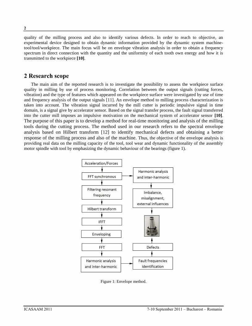
The purpose of this paper is to develop a method for real-time monitoring and analysis of the milling
tools during the cutting process. The method used in our research refers to the spectral envelope
analysis based on Hilbert transform [12] to identify mechanical defects and obtaining a better
response of the milling process and also of the machine. Thus, the objective of the envelope analysis is
providing real data on the milling capacity of the tool, tool wear and dynamic functionality of the assembly
motor spindle with tool by emphasizing the dynamic behaviour of the bearings (figure 1).
Figure 1: Envelope method.
3
7-10 September 2011 – Bucharest – Romania ICASAAM 2011
3 Experimental setup
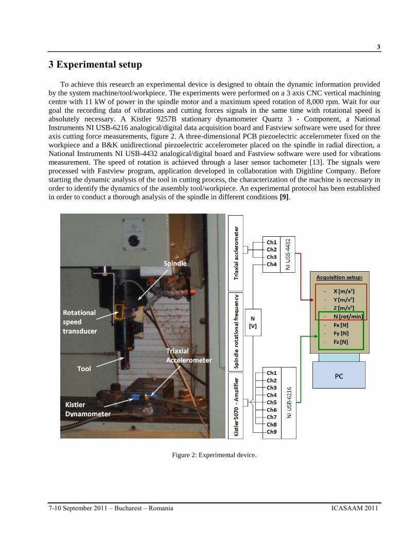
To achieve this research an experimental device is designed to obtain the dynamic information provided
by the system machine/tool/workpiece. The experiments were performed on a 3 axis CNC vertical machining
centre with 11 kW of power in the spindle motor and a maximum speed rotation of 8,000 rpm. Wait for our
goal the recording data of vibrations and cutting forces signals in the same time with rotational speed is
absolutely necessary. A Kistler 9257B stationary dynamometer Quartz 3 - Component, a National
Instruments NI USB-6216 analogical/digital data acquisition board and Fastview software were used for three
axis cutting force measurements, figure 2. A three-dimensional PCB piezoelectric accelerometer fixed on the
workpiece and a B&K unidirectional piezoelectric accelerometer placed on the spindle in radial direction, a
National Instruments NI USB-4432 analogical/digital board and Fastview software were used for vibrations
measurement. The speed of rotation is achieved through a laser sensor tachometer [13]. The signals were
processed with Fastview program, application developed in collaboration with Digitline Company. Before
starting the dynamic analysis of the tool in cutting process, the characterization of the machine is necessary in
order to identify the dynamics of the assembly tool/workpiece. An experimental protocol has been established
in order to conduct a thorough analysis of the spindle in different conditions [9].
Figure 2: Experimental device.
4
ICASAAM 2011 7-10 September 2011 – Bucharest – Romania
4 Measurement and analysis
To increase the forces and to obtain a better response for the monitoring the test was performed on steel
materials workpiece E24-2, the tool milling cutter were used here is 490-025C5-08M, with 25 mm diameter
and 3 teeth. The study is focused on dynamic behaviour analysis of the mill cutter during the cutting process
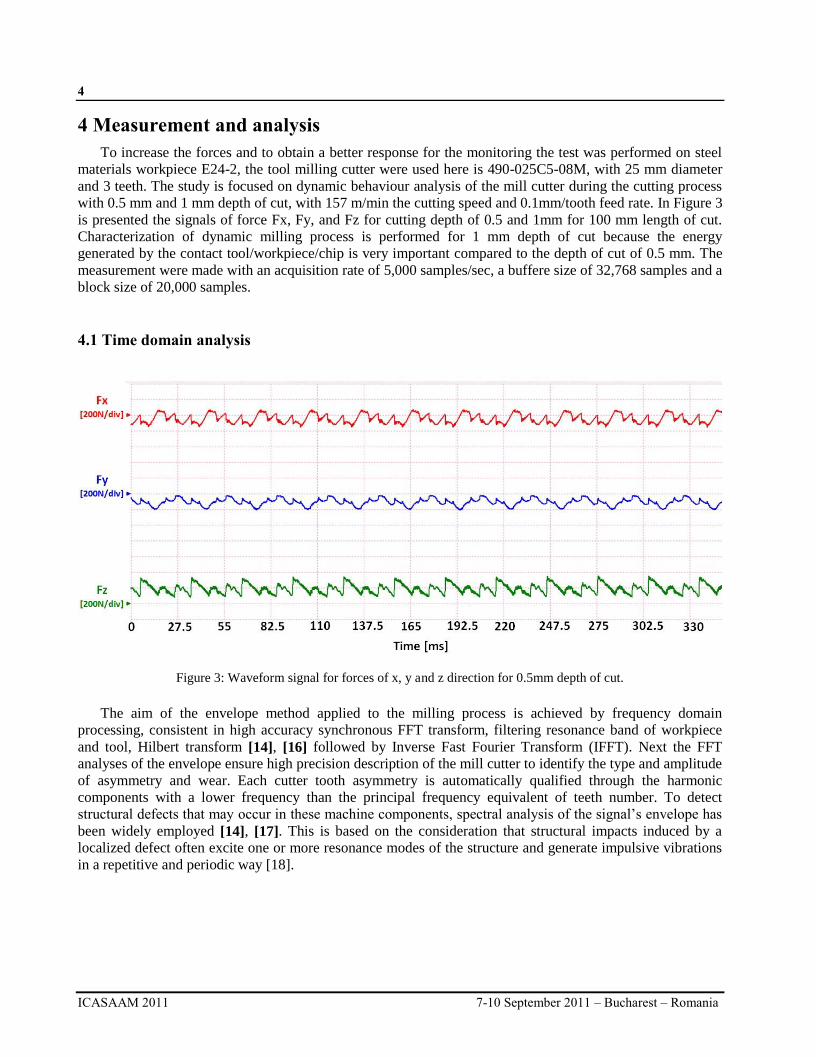
with 0.5 mm and 1 mm depth of cut, with 157 m/min the cutting speed and 0.1mm/tooth feed rate. In Figure 3
is presented the signals of force Fx, Fy, and Fz for cutting depth of 0.5 and 1mm for 100 mm length of cut.
Characterization of dynamic milling process is performed for 1 mm depth of cut because the energy
generated by the contact tool/workpiece/chip is very important compared to the depth of cut of 0.5 mm. The
measurement were made with an acquisition rate of 5,000 samples/sec, a buffere size of 32,768 samples and a
block size of 20,000 samples.
4.1 Time domain analysis
Figure 3: Waveform signal for forces of x, y and z direction for 0.5mm depth of cut.
The aim of the envelope method applied to the milling process is achieved by frequency domain
processing, consistent in high accuracy synchronous FFT transform, filtering resonance band of workpiece
and tool, Hilbert transform [14], [16] followed by Inverse Fast Fourier Transform (IFFT). Next the FFT
analyses of the envelope ensure high precision description of the mill cutter to identify the type and amplitude
of asymmetry and wear. Each cutter tooth asymmetry is automatically qualified through the harmonic
components with a lower frequency than the principal frequency equivalent of teeth number. To detect
structural defects that may occur in these machine components, spectral analysis of the signal’s envelope has
been widely employed [14], [17]. This is based on the consideration that structural impacts induced by a
localized defect often excite one or more resonance modes of the structure and generate impulsive vibrations
in a repetitive and periodic way [18].

5
7-10 September 2011 – Bucharest – Romania ICASAAM 2011
Figure 4: Waveform signal for forces of x, y and z direction for 1mm depth of cut.
Figure 5: Waveform signal for acceleration of x, y and z direction for 1mm depth of cut.
The same evolution is observed in the case of accelerations, figure 5 shows the waveform of the acceleration
signal measured on the three directions during milling processing. It can be seen that the amplitudes of the X
direction (the feed direction of the tool) and Y (the cutting direction of the tool) are much higher than the Z
direction (axial direction of the tool).

6
ICASAAM 2011 7-10 September 2011 – Bucharest – Romania
4.2 Frequency domain analysis
Forces analysis continues to apply FFT on the signal measured in time and obtain frequency spectrum due to
the milling process, shows in figure 6, 7 and 8 for 1mm depth of cut.
Figure 6: Waterfall diagram of Fx forces for 1mm depth of cut.
Figure 7: Waterfall diagram of Fx forces for 1mm depth of cut.
7
7-10 September 2011 – Bucharest – Romania ICASAAM 2011
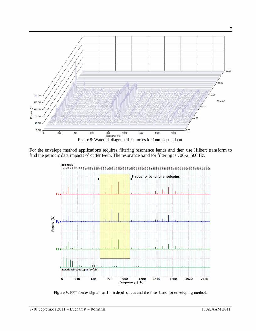
Figure 8: Waterfall diagram of Fx forces for 1mm depth of cut.
For the envelope method applications requires filtering resonance bands and then use Hilbert transform to
find the periodic data impacts of cutter teeth. The resonance band for filtering is 700-2, 500 Hz.
Figure 9: FFT forces signal for 1mm depth of cut and the filter band for enveloping method.

8
ICASAAM 2011 7-10 September 2011 – Bucharest – Romania
Figure 10: FFT vibration signal for 1mm depth of cut and the filter band for enveloping method.
4.3 Envelope analysis
Frequencies related to such resonance modes are often located in higher frequency regions than those
caused by machine-borne vibrations, and are characterized by an energy concentration within a relatively
narrow band centred at one of the harmonics of the resonance frequency.
Figure 11: The waveform signal enveloping for forces.

9
7-10 September 2011 – Bucharest – Romania ICASAAM 2011
By utilizing the effect of mechanical amplification provided by structural resonances, defect-induced
vibration features can be separated from the background noise and interference for diagnosis purpose [14].
Figure 12: The waveform signal enveloping for vibration.
With dynamic information tool and workpiece can apply the enveloping synchronous method to evaluate
with high precision the cutting quality of the tool (figure 9 and figure 10). The objective here is to accurately
track the transfer power by tooth workpiece contact and its harmonic distribution. The aim of the envelope
method applied to the milling process is achieved by frequency domain processing, consistent in high
accuracy synchronous FFT transform, filtering resonance band of workpiece and tool, Hilbert transform [17]
followed by Inverse Fast Fourier Trans- form (IFFT), figure 11 and figure 12. Next the FFT analyses of the
envelope ensure high precision description of the mill cutter to identify the type and amplitude of asymmetry
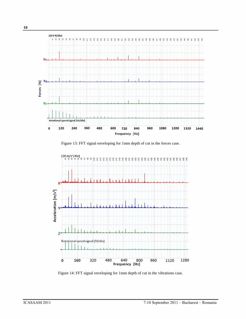
and wear (figure 13 and figure 14). Each cutter tooth asymmetry is automatically qualified through the
harmonic components with a lower frequency than the principal frequency equivalent of teeth number. By
applying FFT on the signal envelope can be observed harmonic frequency of order 3 corresponding to the
activity of the three teeth but very important is the existence of order 2, were the amplitude is very close to
the 3nd order harmonic. This 2nd order harmonic shows the asymmetry existence of the tool cutter. This
effect leads to a cause of wear of the teeth cutter or even more to misalignment teeth/tool cutter.
10
ICASAAM 2011 7-10 September 2011 – Bucharest – Romania
Figure 13: FFT signal enveloping for 1mm depth of cut in the forces case.
Figure 14: FFT signal enveloping for 1mm depth of cut in the vibrations case.

11
7-10 September 2011 – Bucharest – Romania ICASAAM 2011
5 Conclusion Research on vibration analysis of rotating elements has developed surveillance techniques by the methods
of envelope to detect defects on bearings or gears [19], [20]. The transposition of these methods adapted to
the field of machining combined with sampling techniques and signal processing by applying FFT
synchronous and Hilbert transform has demonstrated a very promising results. This paper proposed a method
of dynamic analysis based on envelope analysis method with the purpose to identify and evaluate the
dynamic behaviour of the tool during cutting process. An experimental protocol was designed and developed
for the acquisition, processing and analyzing of the three-dimensional vibration and force signal. The
vibration signals are the result of a mixture of different sources corresponds to components of machines,
making it difficult to identify the state of damage to a particular component. Adapting envelope spectral
analysis to characterize the milling tool is an important contribution for the qualitative and quantitative
characterization of milling capacity. The vibration envelope analysis is proposed to detect the cutting capacity
of the tool necessary for process quality on-line monitoring. In under way this method represents a source for
cutting parameters optimization. Is useful both, dynamic characterization of the tool and also for the
monitoring process and maintenance. If the vibration acceleration signals are the source of chatter vibration,
it would develop the indicators able to detect one of the most problematic phenomena in machining. In the
future we are interested in creating a dynamic three-dimensional model [21], [22
Acknowledgement:This paper was supported by CNCSIS-UEFISCSU, project PNII-RUcode194/2010.
References [1] X. Li, “Flute breakage detection during end milling using Hilbert–Huang transform and smoothed nonlinear energy operator”, International
Journal of Machine Tools & Manufacture, 47, 2007, pp. 1011–1020.
[2] Dragos¸ A. Axinte, Nabil Gindy, Kate Fox, Iker Unanue, “Process monitoring to assist the workpiece surface quality in machining”, International Journal of Machine Tools & Manufacture, 44, 2004, pp. 1091–1108.
[3] C. F. Bisu, P. Darnis, A. Gérard, J-Y Knevez, “Displacements analysis of self-excited vibrations in turning” International Journal of Advanced Manufacturing Technology, 44, (1-2), 2009, pp. 1-16, DOI : 10.1007/s00170-008-1815-8.
[4] C. F. Bisu, A. Gérard, J-Y Knevez, R. Laheurte, O. Cahuc, “Self-excited vibrations in turning : Forces torsor analysis” International Journal of
Advanced Manufacturing Technology,. 44, (5-6), 2009, pp. 447-462, DOI : 10.1007/s00170-08-1850-5. [5] B. Kilundu, X.Chiementin, J. Duez, D. Mba, “Cylostationary of acoustic emission (AE) for monitoring bearing defects”, Mechanical systems and
signal Processing, 25, (6), 2011, pp. 2061-2072, DOI: 10.1016/j.ymssp.2011.01.020.
[6] O. Cahuc, Ph. Darnis, A. Gérard, J-L. Battaglia, "Experimental and analytical balance sheet in turning applications", International Journal of Advanced Manufacturing Technology, 18, 2001, pp. 648-656.
[7] M. Lalanne, G. Ferraris, “Rotordynamics prediction in Engineering” Wiley, 2001.
[8] Dron, J-P., Bolaers, F., Rasolofondraibe, L.,”Improvement of the sensibility of scalars indicators thanks to de-noising method by spectacle subtraction, Application to the detection ball bearing defects”. Journal of Sound Vibration, 270, (4), 2004, pp. 61-73.
[9] Mobley, R-K., “Root Cause Failure Analysis” (Plant Engineering Maintenance Series), Butterworth-Heineman, 1999.
[10] C. F.Bisu, M. Zapciu, A. Gérard, V. Vijelea, M. Anica,” New approach of envelope dynamic analysis for milling process”, Eighth International Conference on High Speed Machining, Metz, France, Dec. 8-10, 2010.
[11] Arnaud, L. and Gonzalo, O. and Seguy, S. and Jauregi, H. and Peigné, G., “Simulation of low rigidity part machining applied to thin-walled
structures, International Journal of Advanced Manufacturing Technology”, 54, 2011, pp. 479-488, doi: 10.1007/s00170-010-2976-9. [12] Zaghbany, I. and Songmene, V., Estimation of machine-tool dynamic parameters during machining operation through operational modal
analysis, International Journal of Machine Tools & Manufacture, 49, (12-13), 2009, pp. 947–957.
[13] Al-Dossary, S, Hamzah, R.I.R., Mba, D., Observations of changes in acoustic emission waveform for varying seeded defect sizes in a rolling element bearing, Journal of Applied Acoustics 70, (1), 2009, pp. 58–81.
[14] R. Yan, R. X. Gao, “Multi-scale enveloping spectrogram for vibration analysis in bearing defect diagnosis”, Tribology International 42, 2009, pp.
293–302.
[15] T.Kalvoda; Y.R. Hwang; "A cutter tool monitoring in machining process using Hilbert-Huang transform", International Journal of Machine
Tools and Manufacture, 50, (5), 2010, pp. 495-501.
[16] V. Gagnol, T-P. Le, P. Ray, “Modal identification of spindle-tool unit in high-speed machining”, Mechanical Systems and Signal Processing, 25, (11), 2011, pp. 2388-2398, doi:10.1016/j.ymssp.2011.02.019.
[17] X. Wang, “Numerical Implementation of the Hilbert Transform”, Thesis, University of Saskatchewan, Saskatoon, 2006.
[18] Mba, D. and Rao, R-B-K-N., Development of acoustic emission technology for condition monitoring and diagnosis of rotating machines:bearings, pumps, gearboxes, engines,and rotating structures, International Journal of Machine Tools & Manufacture, 45, 2005, pp.
1295-1300.
[19] F. Girardin, “Etude de l’usinage de matériaux performants et surveillance de l’usinage“, Thesis Institut National de Sciences Appliquées de Lyon, 2010.

12
ICASAAM 2011 7-10 September 2011 – Bucharest – Romania
[20] X.Chiementin, “Localisation et quantification des sources vibratoires dans le cadre d'une maintenance préventive conditionnelle en vue de
stabiliser le diagnostic et le suivi de l'endommagement des composants mécaniques tournants : application aux roulements à billes”, Thesis Université de Reims Champagne Ardenne, 2007.
[21] C.F. Bisu, P. Darnis, A. Gérard, J-Y K’nevez, “Displacements analysis of self-excited vibrations in turning” International Journal of Advanced
Manufacturing Technology, Springer London, 44, (1-2), 2009, pp. 1-16, (Online), DOI 10.1007/s00170-08-1815-8. [22] O. Cahuc, J-Y. K’nevez, A. Gérard, P. Darnis, G. Albert, C. F. Bisu, C. Gérard, “Self-excited vibrations in turning: cutting moment analysis”,
International Journal of Advanced Manufacturing Technology, 47, (1-4), 2010, pp.217-225, (Online), DOI: 10.1007/s00170-009-2189-2.