the micrography of metals in ultra-violet...
TRANSCRIPT

The Micrography o f Metals in Ultra-Violet Light 671
the propagation of long waves which was put forward by G. I. Taylor. Taylor has proved that one can determine the period of free oscillation of the atmosphere from the speed of long waves. Now the wave which was caused by the Krakatau eruption in 1883 and which went round the world several times was propagated with a speed which corresponds to a period of free oscillation of about 10Jr hours. A similar speed was found by Whipple for the wave of the Great Siberian Meteor.
A method is given for determining the forced tidal oscillation of a horizontally uniform atmosphere on a rotating globe, and is applied to the atmosphere mentioned above. It is found that the existence of the semidiurnal free oscillation restricts in some measure the possible temperature distribution in the upper atmosphere.
The Micrography of Metals in Ultra-Violet Light
By J. Smiles, A.R.C.S. (National Institute for Medical Research), and H. W r ig h t o n , B.Met. (The Research Department, Woolwich)
(<Communicated by J. E. Barnard, F.R.—Received 11 September, 1936)
[Plates 28-34]
In t r o d u c t io n
The resolution of metallic structures under the microscope has, during many years, been limited to that given by oil immersion apochromatic objectives of N.A. 1-30 or 1-40. With such objectives fine lamellar structure of the order of 140,000 lines per inch can be resolved.
In October, 1933,* one of the authors published micrographs taken with a new monochromatic objective! for metallurgy designed to work in a narrow band of the visual deep blue at a wave-length of approximately 4395 A., and having the large numerical aperture of 1 -60. With this objective lamellar structure measuring 180,000 lines per inch has been resolved.
* Wrighton, ‘ J. R. micro. Soc.,’ vol. 53, p. 328 (1933).t This objective was computed by R. J. Bracey, of the British Scientific Instruments
Research Association, and made by Messrs. R. & J. Beck, Ltd.
VOL. CLVIII.— A. 2 Z
on June 26, 2018http://rspa.royalsocietypublishing.org/Downloaded from

672 J. Smiles and H. Wrighton
Using direct and dark ground methods of illumination, Barnard has amply demonstrated the superiority of a system using ultra-violet radiation over those used in the visual examination of certain forms of living biological material. He has shown that the greater resolution to be expected on theoretical grounds from the use of shorter wave-lengths is fulfilled, and that the correction of the quartz objectives is of a very high order.
It is only quite recently that any serious attempt has been made to apply dark ground methods of illumination to the metallurgical microscope at the higher powers. Special appliances combining high power objectives, of somewhat restricted aperture, with dark ground illuminating arrangements, are now available, but their use has not as yet become widely adopted. No such equipment is yet available in quartz objective systems.
Ultra-violet radiation has been applied to the metallurgical microscope by a few workers, notably F. Lucas. In June, 1934, however, shortly before the present work was commenced, Lucas* expressed preference for the results he had obtained using a blue light monochromat of N.A. 1-60 newly introduced by Zeiss. This objective is evidently of similar general character to the one mentioned above.
The apparatus herein described was devised and the photographs with ultra-violet radiation were taken at the National Institute for Medical Research. The investigation there has been undertaken (by one of us, J. S.) with the object of obtaining further knowledge of the fine structure of materials of medical importance and interest, particularly of the teeth. It was necessary, however, in the first instance to test the apparatus and the method on material of which the fine microscopical structure was already known. For this purpose the apparatus has been used with an ultra-violet wave-length on a series of metals and alloys.
This part of the work was therefore designed to explore the possibilities of obtaining higher resolution of the microstructures of metals and alloys by the use of ultra-violet radiation, in comparison with that given by the newly introduced visual light system.
The authors have used the general method of illumination of the metallurgical microscope, that known as “ vertical illumination ”, in which the incident beam of light is passed through the objective to the specimen. The incident beam is, in relation to the reflected image-forming beam, very intense, and reflexion from the air glass surfaces of the objective is liable to set up an amount of glare sufficient to obliterate image detail
* Lucas, * J. Franklin Tnst.,’ vol. 217, p. 661 (1934).
on June 26, 2018http://rspa.royalsocietypublishing.org/Downloaded from

The Micrography o f Metals i Ultra-Violet Light 673
in which contrast is low. This trouble occurs particularly when the outer curvature of the back component of the objective is small. For this reason, objectives for metallurgical work should be computed with bold curvatures, but unfortunately very few objectives are constructed with attention to metallurgical requirements.
In Bracey’s computation for the visual light monochromat, glare has been satisfactorily reduced, and the corrections of this objective permit the whole of the numerical aperture to be used without detriment to the image.
The results obtainable with this objective may be accepted as representative of the highest performance as yet attainable with the metallurgical microscope, and these have been used as a standard of comparison in the present work.
The quartz objectives at the authors’ disposal were primarily designed for the photography of transparent objects by transmitted light using monochromatic radiation of wave-length 2750 A. Each consists of a number of simple fused quartz lenses—seven for the highest powers— with the result that the number of air-solid surfaces is greater than for visual objectives of similar aperture.
It was, therefore, not known to what extent the reflexions from these surfaces would impair the quality of the images formed. It was considered that apart from image deterioration arising from this cause, many metal substances should prove almost ideal objects; some, notably aluminium, reflect a high percentage of ultra-violet light, whilst one difficulty of biological work, depth in the object, might not be encountered with suitably prepared specimens.
For this work an illuminating system has been used which is considered to reduce to a minimum the production of glare in any objective, by admitting to the microscope no light other than the strict counterpart of the image-forming beam reflected from the specimen.
In the early days of ultra-violet photomicrography, the success of focussing an object, particularly with a specimen in which the contrast between elements of structure is low, was largely a matter of chance. No microscope adjustment was sufficiently sensitive and free from irregularity to permit of changes in focus of the necessary precision being made, whilst focussing by means of the auxiliary uranium eyepiece was equally insensitive.
Barnard* has overcome these difficulties by the use of interchangeable objective holding plates designed so as to be replaceable on the microscope
* Barnard and Welch, “ Practical Photo-Micrography,” 3rd edit., 1936, p. 309.
on June 26, 2018http://rspa.royalsocietypublishing.org/Downloaded from

674 J. Smiles and H. Wrighton
with great precision. The objectives,* together with their plates, are centred one to another, and, within narrow limits, are parfocal. The objectives may be interchanged without disturbance of the specimen or of the focussing adjustment of the microscope. Barnard has also introduced a fine focussing adjustment capable of moving the objective through definite intervals of one ten-thousandth of a millimetre.
The authors gratefully acknowledge their indebtedness to Mr. Barnard’s pioneer work and have taken full advantage of the improvements he has introduced.
I llu m in a tio n
The visual light illuminating system which has been adopted for this work is shown diagrammatically in fig. 1, in which S, a Point-o-lite lamp, is the source.
Fig. 1.
The lenses L1? L2, the slip reflector, and the objective O form a centred optical system, which produces a secondary image of a portion of the source in the plane of the object when the objective is adjusted to form a primary image of the object in the focal plane of the eyepiece. The primary image of the source, formed by the short focus condensing lens Li, lies in the plane of the iris D 2 which is mounted concentrically with the axis of the system. The plane of the iris Dx immediately behind Lx, and one close to the back surface of the objective are conjugate planes of the lens L2. It follows that a sharp image of D 2 will be seen in the image plane of the eyepiece and that the brightness and evenness of illumination of the image will remain unaffected by varying its aperture.
The aperture of Dx determines the effective working aperture of the objective. The practical features of this system are as follows:
The size of the illuminated field of the specimen may be restricted,
* These objectives are by Carl Zeiss, Jena.
on June 26, 2018http://rspa.royalsocietypublishing.org/Downloaded from

The Micrography o f Metals in Ultra-Violet Light 675
thereby reducing glare, without in any degree affecting the working aperture of the objective.
The iris Dx may be adjusted to restrict the light entering the microscope to that just required to fill the aperture of the objective; D x may be further restricted to reduce the effective aperture of an objective without any disturbance of the evenness of illumination of the field.
To obtain maximum resolution, objectives should be so free from spherical aberration that the whole of their apertures may be used. In the present work the whole of the aperture of each objective has been used.
The diagram, fig. 2, shows the method of introducing the ultra-violet illuminating system. The ultra-violet source S' is a condensed spark between cadmium electrodes. By means of the lens L \ and the dispersing
F ig. 2.
prisms P1 and P2, a primary image in the wave-length 2750 is formed in the plane of the iris D 2. The quartz objective forms a primary image of the diaphragm and a secondary image of the source in the object plane. The prisms are adjusted for minimum deviation of an axial ray through L \. This ray passes approximately through the centre of each prism face, and on leaving the last of these at the point C is coincident with the axis of the visual system.
A fluorescent screen U is placed behind the slip reflector (which is of fused quartz) at a distance equal to that of the last surface of the objective in front of the slip. In order that the objective may be filled with ultraviolet light, the diameter of the image of D 'x on the screen U should be the same as that of the last surface of the objective.
The lens L2, which is of quartz, is common to both systems, and once adjusted in visual light remains undisturbed. The centralization of the
on June 26, 2018http://rspa.royalsocietypublishing.org/Downloaded from

676
ultra-violet system is checked by the coincidence of the visual and the ultra-violet images on the screen U. Since the objectives in use are mounted on the Barnard changing plates to be co-axial, they will be axially illuminated by either system.
J. Smiles and H. Wrighton
A d ju stm en t
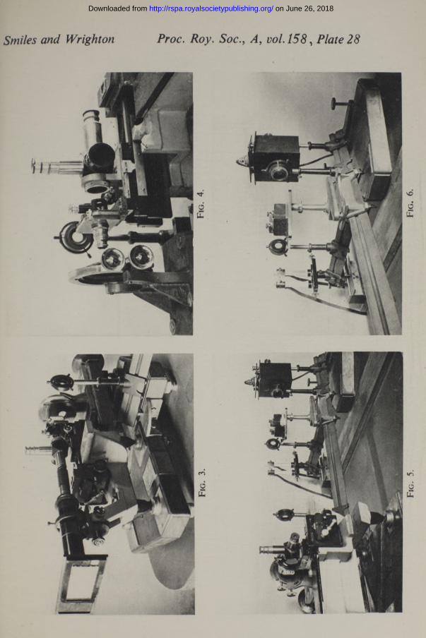
The illustrations, figs. 3, 4, 5, 6, Plate 28, are general views of the microscope and the illuminating systems and show the method of mounting the optical components of the latter. Fig. 3 shows the microscope with camera attached. The stage is mounted on a separate base, and is provided with suitable adjustments by which the object plane can be set perpendicular to the axis of the objective. The Barnard objective changer is illustrated in fig. 4. Mounted immediately behind, and independent of the objective, is the vertical illuminator. The illuminating systems shown in figs. 5 and 6 are mounted on two optical benches which are fitted with levelling screws. One end of the bench carrying the spark gap and dispersing system is attached to a casting in which are two levelling screws, one of which rests in a conical hole and the other on a horizontal flat, which are carried on a saddle resting on the other bench. The other end of this bench rests on a horizontal flat. The dispersing system can therefore be rotated about a vertical axis. The prism P2 is mounted on a table so that the axis of rotation lies in the plane of the last face and passes through the point C (fig. 2). The prism table can swing away from the path of the visual system when it is desired to use the latter.
The bench carrying the visual system is also fitted with levelling screws. It is adjusted so that the axis of the illuminating system lies in a horizontal position. The height of the axis is then adjusted by raising the optical components until it passes through the point of intersection of the axis of the objective and the first face of the reflector Rx (fig. 2). The bench carrying the dispersing system is adjusted so that the axis of is horizontal and at the same height as that of the visual system. This can be carried out by adjusting the benches so that the intersections of their bearing faces lie in a horizontal plane. The spark gap and the lens Lx are placed on the bench carrying the visual system and their heights adjusted to the visual axis. They are then replaced on their own bench.
Final adjustment is carried out by illuminating the object by means of the visual system in conjunction with the quartz objective. The quartz slip of the illuminator, and the lens and iris L2D 2, are adjusted to obtain accurate centralization both of the incident light as it enters the objective
on June 26, 2018http://rspa.royalsocietypublishing.org/Downloaded from

The Micrography of Metals Ultra-Violet Light 677
and of the illuminated field area. The exact position of the image of the iris in the plane of the screen U is then noted. The table carrying the prisms is swung into position, and by rotating the bench carrying the dispersing system, an image of the source S' in the wave-length 2750 A. is allowed to fall centrally on the iris D 2. The position of the image of D 'x on the screen U is noted. Should this be horizontally displaced from the position occupied by the image of Dx, then the two systems will not be co-axial, and this is corrected by adjusting the position of the prism Px whilst rotating the bench carrying the dispersing system so as to maintain the image of the spark on the iris D 2.
The diameter of the iris D 'x is adjusted so that its image on U is equal to the diameter of the back lens of the objective.
The first tests were made with a low power quartz objective of a focal length 6 mm. and numerical aperture 0-35. Since all the quartz objectives used were corrected for work with covered objects, a quartz slip was introduced, but in the present work it was found preferable to mount the slip immediately in front of the objective rather than on the specimen in order to minimize the effect of reflexions from its surfaces.
This was followed by the use of a lens of focal length 2-5 mm. and N.A. 0-85 with similar satisfactory results.
Finally the highest power quartz monochromat was used. This has a focal length of 1-7 mm. and N.A. of 1-25. Comparative photographs of almost identical fields in a number of metals and alloys were taken with this lens and with the visual light objective of N.A. 1 -60.
The results obtained with this last quartz objective again proved sufficiently glare-free to permit of satisfactory imaging of the finest detail even of surfaces specially delicately etched. The negatives obtained were not quite so contrasty as the corresponding visual light images. This may be due in part to the exceptional freedom from glare of the visual light monochromat, but is in the main due to the low penetration of ultra-violet light in the gelatine of the plate which is a cause of some weakening of contrast in all classes of ultra-violet light microscopy.
With neither of the two lenses is there a large flat field available, and only the centre (approximately one-third diameter) of the field in the X 10 ocular was photographed. The illuminated field was carefully restricted to cover a plate field of 2 \ inches diameter, thereby further reducing glare, which invariably makes its appearance when a large field is illuminated.
By trial and error methods, and careful examination of many photographs, the optimum tube length for the quartz objective in conjunction with the X 10 quartz ocular was determined. The fixed extension
on June 26, 2018http://rspa.royalsocietypublishing.org/Downloaded from

camera in use gave with this system a magnification of about 2200 diameters.
The visual light photographs were taken at Woolwich with a new photo- micrographic outfit recently installed there, the camera being adjusted to give a measured magnification of x 2500. The visual light negatives have been printed by contact, whilst the ultra-violet negatives have been printed by projection and enlarged a little to make the illustrations comparable in size.
Under these conditions, when the correct working tube length of the quartz lens had been determined, ultra-violet photographic images were obtained showing sharp definition and high resolution, obviously a little in advance of that given by the visual light monochromat.
The equivalent aperture of the quartz objective is 24% higher than the N.A. of the 1 -60 visual light objective. On the other hand, the actual angular aperture of the quartz objective is lower, and this may, under some conditions, tend to reduce its advantage; this point will be referred to below in relation to the preparation of specimens.
678 J. Smiles and H. Wrighton
P r epa r a tio n o f M etal Specim ens
In relation to the minuteness of detail seen in the microscope, the methods of preparation of metal specimens seem forceful and crude. I n the course of attempts made from time to time to secure the maximum clarity of imaging of fine detail in visual light work, some idea has been formed of the refinements desirable in these processes.
The image formed of a metal specimen is in the main a contour image. It is necessary that the relief or contour produced on the specimen should be substantially uniform in depth from grain to grain in the metal and from point to point on the surface; for high power work the relief should be as delicate as possible, and yet the layer of flowed and distorted material set up in the course of preparation must be completely removed.
It is desirable to carry the final stages of abrasive rubbing as finely as possible with avoidance of undue pressure or heating by friction, so as to require a minimum of surface flowing or polishing treatment.
The harder metal specimens used have been finally polished on a 6-inch diameter disk revolving at about 600 revolutions per minute, covered with selvyt cloth and fed with moistened heavy magnesium oxide. The pieces have been of the order of \ inch or f inch square in size, and have required one minute or less of such polishing. Such working results in little surface flow; generally, however, it has been found desirable to
on June 26, 2018http://rspa.royalsocietypublishing.org/Downloaded from

The Micrography o f Metals in Ultra-Violet Light 679
remove the first etch given, by a re-polishing of a few seconds only on the wheel, and then to give a final very light etch.
The aluminium alloys, and some other of the softer metals, have been polished by a method described by Taffs,* using specially prepared alumina on a benzine soaked pad.
A really sharp outline etch of minute structural detail is probably not attainable; the ground material immediately surrounding any attacked element of structure tends to be eaten away and so bevelled, and true image formation is thereby vitiated. The dark spot image of such an attacked particle becomes unduly large and loses shape, and this blurring increases with any reduction of the angular aperture of the optical system. In this respect, the visual light monochromat with its large actual aperture of 1-60 may be at some advantage over the quartz lens.
D iscussion of R esults
The images obtained have shown an increase in resolution and sharpness of detail of an order to be expected from the higher equivalent aperture. There has not been observed any different image formation resulting from selective absorption and reflexion in the ultra-violet when clean etched surfaces reasonably free from deposited etching products have been used. A 4% copper steel examined gave on etching a surface deposit or patina of copper, which, whilst transparent to blue light, was very opaque to the ultra-violet radiation and almost completely masked the structure. This patina was removable by collodion film stripping methods, after which the structure was imaged very clearly in the ultra-violet.
Some non-metallic inclusions have shown selective absorption; whereas brass and bronze, where clearly etched, have photographed quite as might have been expected in a higher aperture visual light system.
The increased resolution has, in the steel specimens, resulted in sharper imaging of isolated minute carbide particles, and in a tendency for fine line structures to become resolved into chains of dots. Structural markings in free Ferrite, not shown under an apochromat of N.A. 1 -30, are seen faintly appearing under the monochromat of 1 - 6 N.A. and more clearly imaged in the ultra-violet photographs.
In one or two cases the specimens have been photographed in addition with an oil-immersion apochromat of 1 • 30 N.A., which is the highest power generally available at present. Comparison of these photographs with the ultra-violet images shows very clearly the advance in resolving power which is available.
* ‘ J. R. micr. Soc.,’ vol. 56, p. 300 (1936).
on June 26, 2018http://rspa.royalsocietypublishing.org/Downloaded from

680 The Micrography of Metals in Ultra-Violet Light
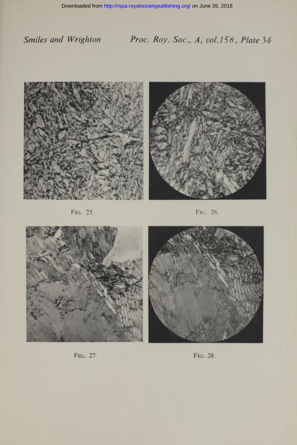
In fig. 28, Plate 34, lamellar structure measuring 200,000 lines per inch is resolved.
In conclusion, the authors wish to express their thanks to Mr. J. E. Barnard, F.R.S., for the interest he has taken in the work and for the loan of apparatus, to the Medical Research Council and the Director of the National Institute for Medical Research, and to Dr. R. H. Greaves, Director of Metallurgical Research, Woolwich Arsenal, for the facilities afforded at these different centres.
E x pla n a t io n of P lates
Plate 29
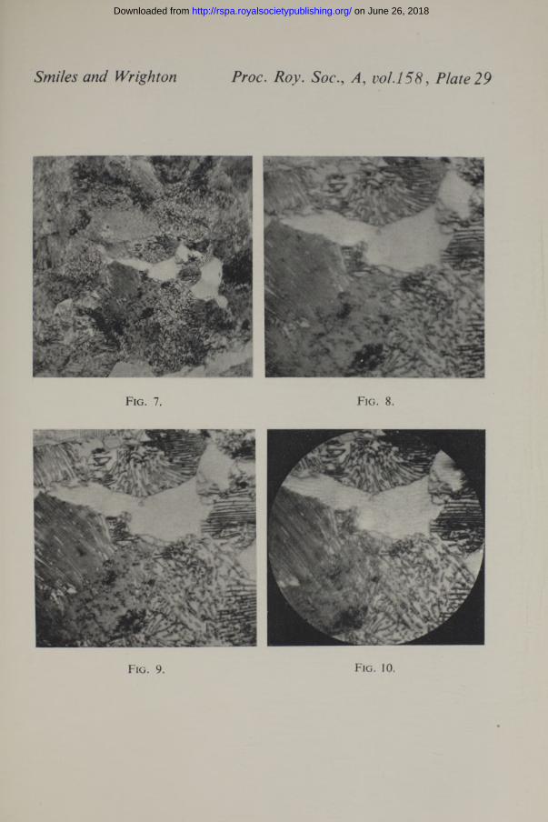
Pearlitic structure in plain carbon steel.
Fig. 7. x 1000, 2 mm. apochromat, N.A. 1-30.Fig. 8. x 2500, 2 mm. apochromat, N.A. 1-30.Fig. 9. x 2500, 2 mm. monochromat, N.A. 1-60, X 4395.Fig. 10. x 2500, 1 -7 mm. quartz monochromat, N.A. 1-25, X 2750.
Plate 30
Sorbitio structure in nickel steel.
Fig . 11. X 500, 4 mm. apochromat, N.A. 0-95.Fig. 12. x 2500, 2 mm. apochromat, N.A. 1 *30.Fig. 13. x 2500, 2 mm. monochromat, N.A. 1-60, X4395.Fig. 14. x 2500, 1 -7 mm. quartz monochromat, N.A. 1-25, X 2750.
Plate 31
Pearlitic structure in 4% copper steel.
Fig. 15. x 2500, 2 mm. monochromat, N.A. 1*60, X4395.Fig. 16. x 2500, 1-7 mm. quartz monochromat, N.A. 1’25, X 2750.F ig. 17. x 2500, 1 -7 mm. quartz monochromat, N.A. 1-25, X 2750.Figs. 15 and 16 are photographs of the specimen as prepared by polishing and etch
ing in the usual manner. The film or patina which has formed on the surface is transparent to the visual radiation but almost opaque to the ultra-violet. After removal of this film by collodion stripping, a clear image of the structure is given, as shown in fig. 17.
Plate 32Sorbitio structure in nickel chrome steel.
Fig. 18. x 2500, 2 mm. monochromat, N.A. 1 -60, X4395.Fig. 19. x 2500, 1-7 mm. quartz monochromat, N.A. 1 -25, X2750.
Veining structure in beryllium-bronze.Fig. 20. x 2500, 2 mm. monochromat, N.A. 1 -60, X4395.F ig. 21. x 2500, 1 -7 mm. quartz monochromat, N.A. 1*25, X 2750.
on June 26, 2018http://rspa.royalsocietypublishing.org/Downloaded from
Smiles and Wrighton Proc. Roy. Soc., A, Plate 28
on June 26, 2018http://rspa.royalsocietypublishing.org/Downloaded from
Smiles and Wright on Proc. Roy. SocA , vol.158, Plate 29
Fig. 7. Fig. 8.
Fig. 9. Fig. 10.
on June 26, 2018http://rspa.royalsocietypublishing.org/Downloaded from

Smiles and Wright on Proc. Roy. A, vo 1.158, Plate 30
F ig. 13. Fig. 14.
on June 26, 2018http://rspa.royalsocietypublishing.org/Downloaded from

Smiles and Wrighton Proc. Roy. Soc., A, , 37
1 *
m£L ja y W * *■' irsisr*s*
Fig. 15.
Fig. 16. Fig. 17.
on June 26, 2018http://rspa.royalsocietypublishing.org/Downloaded from

Smiles and Wright on Proc. Roy. SocA , vol.158,
■m
/
...
• y%:
* "4 Y< ' V v-r;*\ ,1 4T *"̂S
'4 . / r /c v -Hi*~N* «V# , \ ^■ ■ ■•» *—. «V V C \ V \
• V V ^ W - \\ \ . • | - J t V ! - -V y . . * f ' . • / • - • , y ; - f j A
rt**' | »i V V%V * ' 4 • , .
, s ' 4■ ' A m
. \ ' v ‘ y j j - ' fi—>... f t ’l / ■’•»j - ■ f? M l a v ?*.
<• v 'cfc V;
I . <, -V’v . ; X V :jh i j
i Jl K > , . •■.’ v . - v . j •'■•.'■ > - a »
■A?..
%3,r/\<r®5»
F ig. 18. Fig. 19.
Fig. 20. F ig. 21.
on June 26, 2018http://rspa.royalsocietypublishing.org/Downloaded from

Smiles and Wrighton Proc. Roy. Soc., A, , 33
F ig. 22.
:h&•*t ^
r e ? * * * ' •^ , s ^ : i , - w . *
... -+rr~:n‘t£ ,y ' ’? *
' **;V -■<?*) r *>,;•"
- *.L -? - Vv 1 1 ^ ; Z ^* L' ., m•*
-
Fig. 23. Fig. 24.
on June 26, 2018http://rspa.royalsocietypublishing.org/Downloaded from
Smiles and Wrighton Proc. Roy. Soc., A, , Plate 34
Fig. 27. Fig. 28.
on June 26, 2018http://rspa.royalsocietypublishing.org/Downloaded from

Band Spectrum o f Chlorine 681
Plate 33Cold worked 70/30 brass.
Fig . 22. x 500, 4 mm. apochromat, N.A. 0-95.Fig. 23. x 2500, 2 mm. monochromat, N.A. 1-60, X 4395.Fig . 24. x 2500, 1 *7 mm. quartz monochromat, N.A. 1-25, X 2750.
Plate 34Fine Martensite in nickel chrome steel.
Fig. 25. x 2500, 2 mm. monochromat, N.A. 1-60, X 4395.Fig. 26. x 2500, 1 -7 mm. quartz monochromat, N.A. 1-25, X 2750.
Pearlitic structure in plain carbon steel.Fig. 27. x 2500, 2 mm. monochromat, N.A. 1-60, X 4395.Fig. 28. x 2500, 1-7 mm. quartz monochromat, N.A. 1-25, X2750.
The Emission Band Spectrum of Chlorine—IBy A. E l lio t t , Ph.D., D.Sc., and W. H. B. C am eron , M.Sc., Physics
Department, University of Sheffield
0Communicated by S. R. Milner, F.R.S.—Received 24 , 1936)
[Plate 35]
In t r o d u c t io n
It has long been known that chlorine, in addition to its atomic line spectrum, can be made to emit both continua and discrete bands, under suitable conditions of excitation. The chief results hitherto obtained are summarized below: other references to work on the band spectrum of chlorine (both in emission and absorption) may be found in Kayser’s “ Handbuch der Spektroscopie,” vols. 7 and 8.
Measurements of the heads of the visible emission bands have been made by Ota and Uchida,* who have arranged them in three systems. There is, however, serious lack of agreement in the “ vibration frequencies ” (co’s) where agreement should exist, and this has led us to remeasure the band heads of the whole system. These measurements have been extended considerably in the directions both of higher and of lower frequency, and the use of an improved technique has enabled us
* ‘ Jap. J. Phys.,’ vol. 5, p. 53 (1928).
on June 26, 2018http://rspa.royalsocietypublishing.org/Downloaded from