the mcs shade evaluation procedure part 2 how to record ... · the mcs shade evaluation procedure...
TRANSCRIPT
The MCS shade evaluation procedure Part 2 – How to record shade onto the chart
The MCS shade evaluation procedure Part 1 – The procedure explained (previous presentation)
Part 2 – How to record shade onto the chart
a) Summary of methods b) Compass and elevation tool method c) Trigonometry to correct for readings taken on the ground d) Using 3D modelling e) Reflective dome tool f) Transparent acetate tool g) Phone Apps h) Camera methods i) Electronic shade analyser
NOTE: Other methods may also be available … this presentation covers
the most common
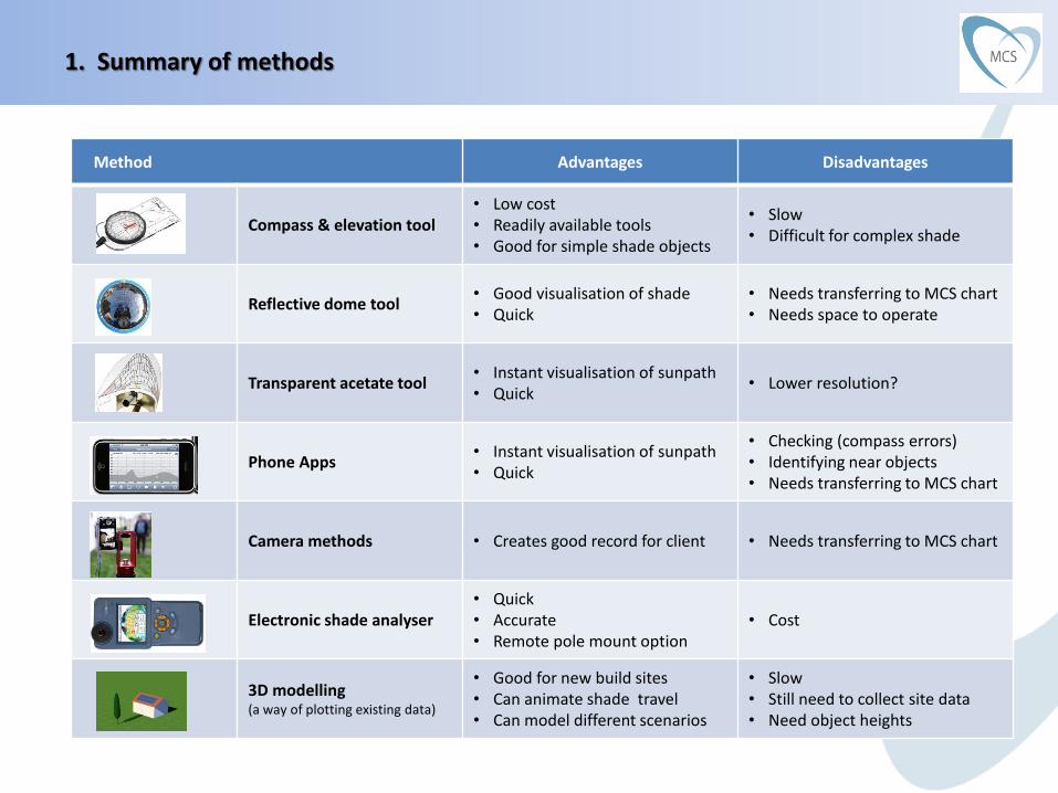
1. Summary of methods
Method Advantages Disadvantages
Compass & elevation tool • Low cost • Readily available tools • Good for simple shade objects
• Slow • Difficult for complex shade
Reflective dome tool • Good visualisation of shade • Quick
• Needs transferring to MCS chart • Needs space to operate
Transparent acetate tool • Instant visualisation of sunpath • Quick
• Lower resolution?
Phone Apps • Instant visualisation of sunpath • Quick
• Checking (compass errors) • Identifying near objects • Needs transferring to MCS chart
Camera methods • Creates good record for client • Needs transferring to MCS chart
Electronic shade analyser • Quick • Accurate • Remote pole mount option
• Cost
3D modelling (a way of plotting existing data)
• Good for new build sites • Can animate shade travel • Can model different scenarios
• Slow • Still need to collect site data • Need object heights

1. Summary of methods
Not mentioned here is the “holding the MCS chart at arms length and
sketching” method
This does not work and should not be used
To understand why … see the acetate tool section

Requires:
1. Compass and elevation tool
2. Compass
3. Elevation tool
1. MCS chart
next slide …

Elevation tool
1. Compass and elevation tool
??
Need to measure angular height of obstacle
Various tools available
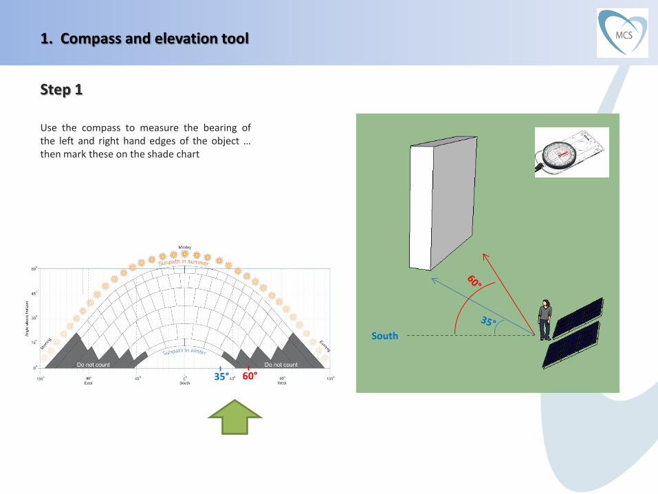
Step 1
Use the compass to measure the bearing of the left and right hand edges of the object … then mark these on the shade chart
1. Compass and elevation tool
South
35° 60°
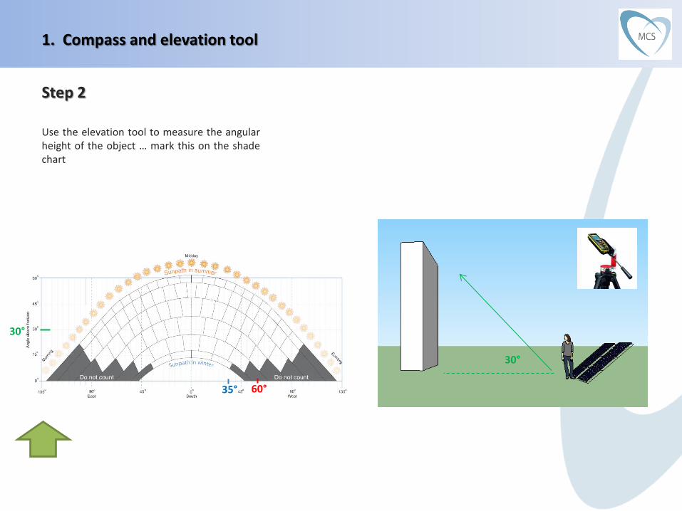
Step 2
Use the elevation tool to measure the angular height of the object … mark this on the shade chart
1. Compass and elevation tool
30°
35° 60°
30°

Step 3
Using the marks … draw the shade object
NOTE: This explanation assumes a single simple shade object. The procedure is the same for multiple or more complex shapes – except that the number of compass and elevation readings required is increased
1. Compass and elevation tool
35° 60°
30°

Complicated horizons
For simplicity, the previous explanation assumed a single simple shade object.
The procedure is the same for multiple or more complex shapes, except that the number of compass and elevation readings required is increased
1. Compass and elevation tool
1 4
2 3
6
7
8 9
10 11
12 13
14 15
For complicated skylines, this method would be very slow

For those into maths … In some circumstances you may need to correct for a reading taken at ground level In the example below … you measure y, but want to know x
2. Trigonometry to correct for readings taken at ground level
h1 = height of measuring instrument above ground h2 = height of PV array above ground
y
x
h1
d1
h2
d2
x = tan-1 (d1 * tan y) – (h2 - h1)
d2
Its ok to skip this slide!
This is a question that has been asked … but unless you are into
maths, you are probably going to want to jump to the next section
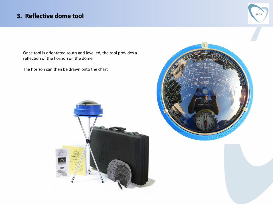
3. Reflective dome tool
Once tool is orientated south and levelled, the tool provides a reflection of the horizon on the dome The horizon can then be drawn onto the chart

3. Reflective dome tool
Standard chart • Very good for visualising where sun is going to be a different
times of day and year .. and how shade will influence the array
• But not ideal for transferring to MCS chart (a t time of writing, no dedicated MCS chart is available for this tool)
Orientation & elevation chart • Best option at moment for use with MCS chart
• Allows shade obstacle locations to be transferred to MCS chart
in a process similar to the compass method
i.e. mark on the MCS chart the orientation & height of all obstacle edges / corners … then fill in
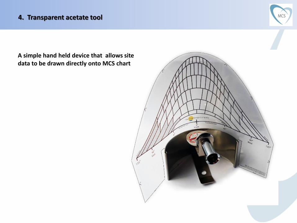
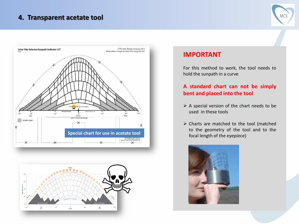
4. Transparent acetate tool
A simple hand held device that allows site data to be drawn directly onto MCS chart

4. Transparent acetate tool
Procedure: a) Insert blank chart into device b) Orientate device south & level c) Look at horizon through integral eyepiece d) Draw horizon onto chart
4. Transparent acetate tool
IMPORTANT For this method to work, the tool needs to hold the sunpath in a curve
A standard chart can not be simply bent and placed into the tool
A special version of the chart needs to be
used in these tools
Charts are matched to the tool (matched to the geometry of the tool and to the focal length of the eyepiece)
Special chart for use in acetate tool
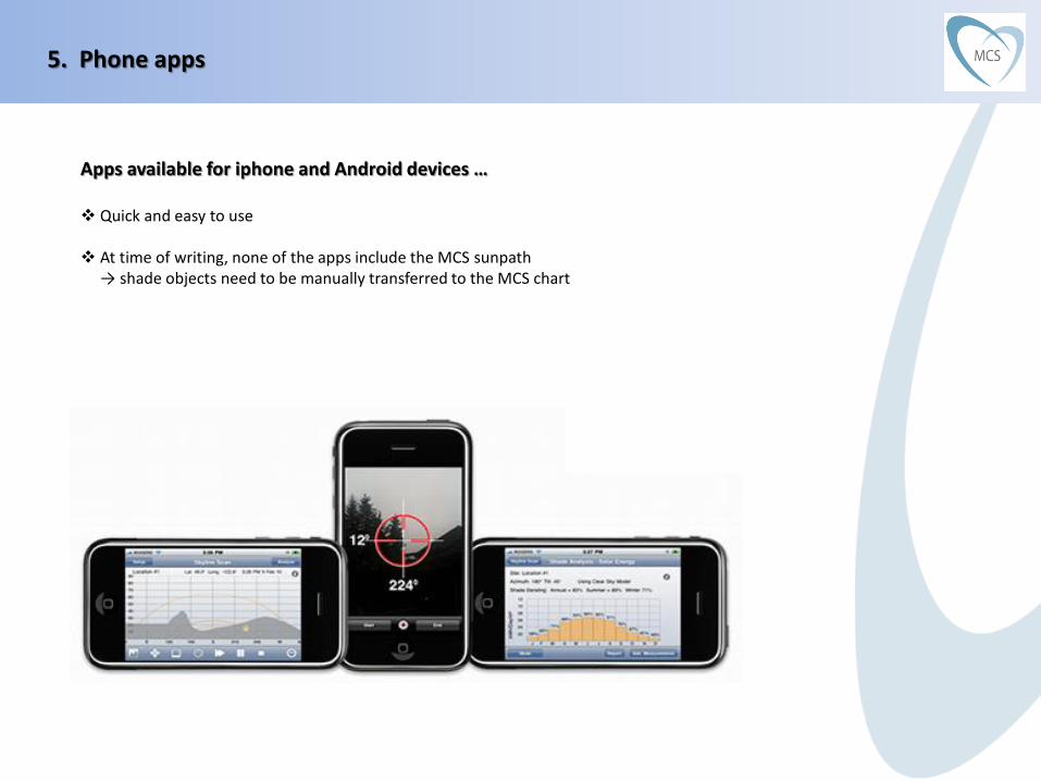
5. Phone apps
Apps available for iphone and Android devices … Quick and easy to use
At time of writing, none of the apps include the MCS sunpath
→ shade objects need to be manually transferred to the MCS chart
5. Phone apps
Apps available for iphone and Android devices … Quick and easy to use
At time of writing, none of the apps include the MCS sunpath
→ shade objects need to be manually transferred to the MCS chart
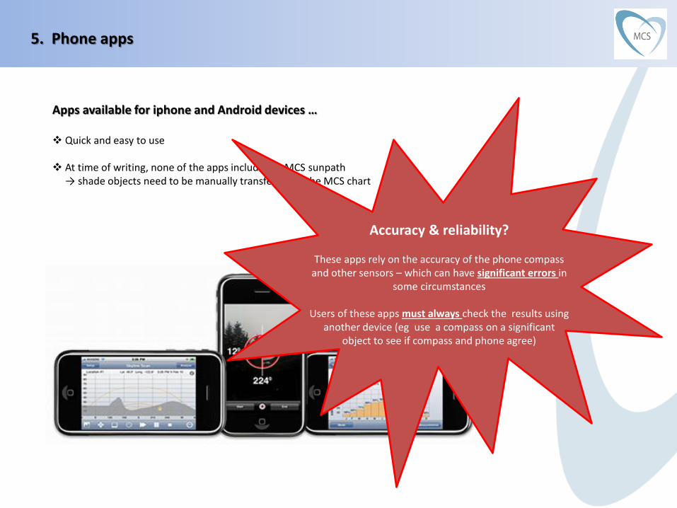
Accuracy & reliability?
These apps rely on the accuracy of the phone compass and other sensors – which can have significant errors in
some circumstances
Users of these apps must always check the results using another device (eg use a compass on a significant
object to see if compass and phone agree)
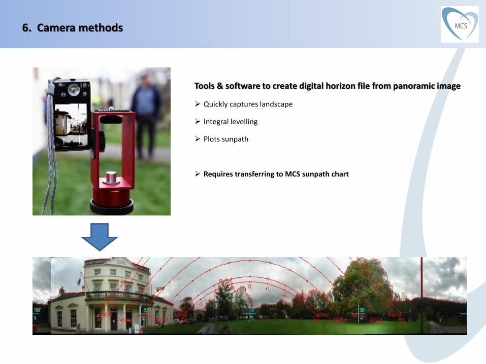
6. Camera methods
Tools & software to create digital horizon file from panoramic image Quickly captures landscape Integral levelling Plots sunpath
Requires transferring to MCS sunpath chart
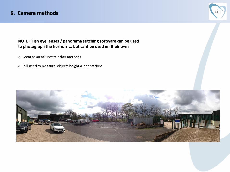
6. Camera methods
NOTE: Fish eye lenses / panorama stitching software can be used to photograph the horizon … but cant be used on their own o Great as an adjunct to other methods
o Still need to measure objects height & orientations
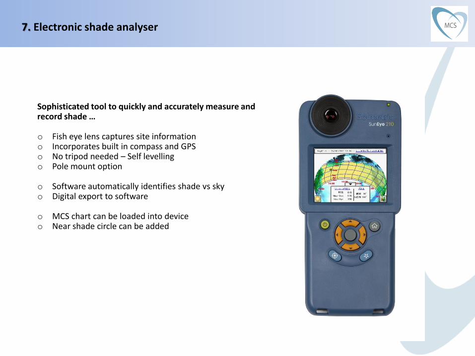
7. Electronic shade analyser
Sophisticated tool to quickly and accurately measure and record shade … o Fish eye lens captures site information o Incorporates built in compass and GPS o No tripod needed – Self levelling o Pole mount option
o Software automatically identifies shade vs sky o Digital export to software
o MCS chart can be loaded into device o Near shade circle can be added

7. Electronic shade analyser
Pole mount and remote capture feature enables roof level readings to be taken while operator stood on ground.
Built in compass, GPS and self levelling feature enable quick measurements without the need of a tripod.

7. Electronic shade analyser
Digital image can be exported to software
MCS chart can be loaded into device … so shade drawn directly onto MCS chart Near shade circle can be added to any near objects
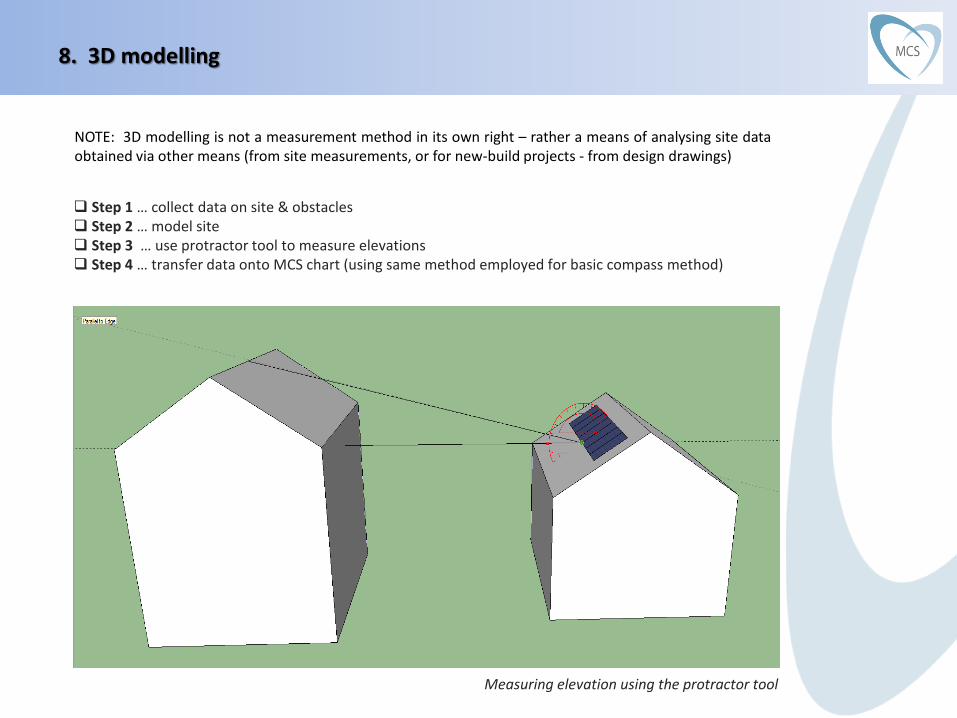
8. 3D modelling
Step 1 … collect data on site & obstacles Step 2 … model site Step 3 … use protractor tool to measure elevations Step 4 … transfer data onto MCS chart (using same method employed for basic compass method)
Measuring elevation using the protractor tool
NOTE: 3D modelling is not a measurement method in its own right – rather a means of analysing site data obtained via other means (from site measurements, or for new-build projects - from design drawings)

8. 3D modelling
3D modelling can be useful in laying out flat roof arrays containing multiple parallel rows Though the same results (for simple systems) can also be obtained via basic trigonometry

8. 3D modelling
An advantage of 3D modelling is that shadow effects can be simulated (good for providing information to client)

8. 3D modelling
3D modelling features are built into many of the proprietary PV software packages … Some of these packages then display the effect of the 3D model
on a sunpath diagram
Information from this sunpath diagram can then be transferred onto the MCS shade chart