the mars survyor '01 rover and robotic arm · web viewthe mars surveyor '01 rover and...
TRANSCRIPT
The Mars Surveyor '01 Rover and Robotic ArmRobert G. Bonitz, Tam T. Nguyen, Won S. Kim
Jet Propulsion LaboratoryCalifornia Institute of Technology
4800 Oak Grove DrivePasadena, CA 91109-8099
Abstract - The Mars Surveyor 2001 Lander will carry with it both a Robotic Arm and Rover to support various science and technology experiments. The Marie Curie Rover, the twin sister to Sojourner Truth, is expected to explore the surface of Mars in early 2002. Scientific investigations to determine the elemental composition of surface rocks and soil using the Alpha Proton X-Ray Spectrometer (APXS) will be conducted along with several technology experiments including the Mars Experiment on Electrostatic Charging (MEEC) and the Wheel Abrasion Experiment (WAE). The Rover will follow uplinked operational sequences each day, but will be capable of autonomous reactions to the unpredictable features of the Martian environment.
The Mars Surveyor 2001 Robotic Arm will perform rover deployment, and support various positioning, digging, and sample acquiring functions for MECA (Mars Environmental Compatibility Assessment) and Mossbauer Spectrometer experiments. The Robotic Arm will also collect its own sensor data for engineering data analysis. The Robotic Arm Camera (RAC) mounted on the forearm of the Robotic Arm will capture various images with a wide range of focal length adjustment during scientific experiments and rover deployment
1. INTRODUCTION
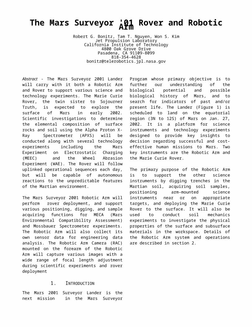
The Mars 2001 Surveyor Lander is the next mission in the Mars Surveyor Program whose primary objective is to further our understanding of the biological potential and possible biological history of Mars, and to search for indicators of past and/or present life. The Lander (Figure 1) is scheduled to land on the equatorial region (3N to 12S) of Mars on Jan. 27, 2002. It is a platform for science instruments and technology experiments designed to provide key insights to decision regarding successful and cost-effective human missions to Mars. Two key instruments are the Robotic Arm and the Marie Curie Rover.
The primary purpose of the Robotic Arm is to support the other science instruments by digging trenches in the Martian soil, acquiring soil samples, positioning arm-mounted science instruments near or on appropriate targets, and deploying the Marie Curie Rover to the surface. It will also be used to conduct soil mechanics experiments to investigate the physical properties of the surface and subsurface materials in the workspace. Details of the Robotic Arm system and operations are described in section 2.
Figure 1 Mars Surveyor 2001 Lander
After the Robotic Arm deploys the Marie Curie rover, the sister of the Mars Pathfinder Sojourner rover, onto the Martian surface, the rover will begin traversing the surface in the vicinity of the Lander. The rover visiting locations will be designated by a human operator using engineering data collected during previous traversals and end-of-sol (Martian day) stereo images captured by the Lander stereo cameras [6]. During the traversals the rover will autonomously avoid rock, drop-off, and slope hazards. It will change its course to avoid these hazards and will turn back toward its goals whenever the hazards are no longer in its way. The rover uses "dead reckoning" counting wheel turns and on-board rate sensors to estimate position. Although the rover telemetry will record its responses to human driver commands in detail, the vehicle's actual positions will not be known until examination of the Lander stereo images at the end of the sol. The rover will stop at several sites of interest for various scientific and engineering experiments.
2. ROBOTIC ARM
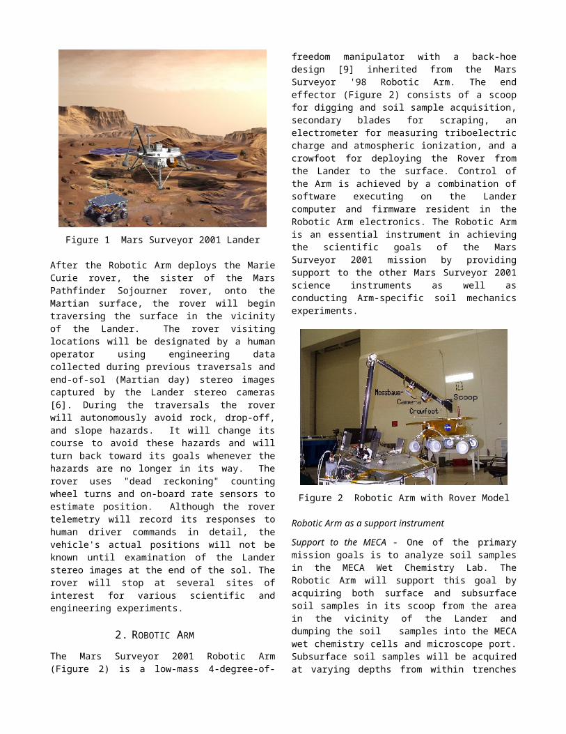
The Mars Surveyor 2001 Robotic Arm (Figure 2) is a low-mass 4-degree-of-freedom manipulator with a back-hoe design [9] inherited from the Mars Surveyor '98 Robotic Arm. The end effector (Figure 2) consists of a scoop for digging and soil sample acquisition, secondary blades for scraping, an electrometer for measuring triboelectric charge and atmospheric ionization, and a crowfoot for deploying the Rover from the Lander to the surface.
Control of the Arm is achieved by a combination of software executing on the Lander computer and firmware resident in the Robotic Arm electronics. The Robotic Arm is an essential instrument in achieving the scientific goals of the Mars Surveyor 2001 mission by providing support to the other Mars Surveyor 2001 science instruments as well as conducting Arm-specific soil mechanics experiments.
Figure 2 Robotic Arm with Rover Model
Robotic Arm as a support instrument
Support to the MECA - One of the primary mission goals is to analyze soil samples in the MECA Wet Chemistry Lab. The Robotic Arm will support this goal by acquiring both surface and subsurface soil samples in its scoop from the area in the vicinity of the Lander and dumping the soil samples into the MECA wet chemistry cells and microscope port. Subsurface soil samples will be acquired at varying depths from within trenches excavated by the Arm, potentially to a depth of 50cm depending on the soil conditions. The Arm is capable of reaching deeper than 50cm below the surface, but operational constraints are expected to limit practical digging depth. The Arm will dump soil samples on the MECA material patch plates for imaging by the Robotic Arm Camera to measure properties such as soil particle wear, hardness, and adhesion. The Arm will also position the MECA electrometer for measuring triboelectric charge during digging and atmospheric ionization.
Support to the Robotic Arm Camera - A key element of the Mars Surveyor 2001 instrument suite is the Robotic Arm Camera (RAC) mounted on the forearm just behind the wrist. Soon after landing the Robotic Arm will position the RAC to take images of the Lander foot pads, providing useful data in determining surface properties at the touchdown site. Throughout the mission the Arm will periodically position the RAC to take images of the surface, trench floor and end walls, and dumped soil piles. During soil sample acquisition, the scoop will be positioned for the RAC to take close-up images of the soil samples in the scoop prior to delivery to the MECA. There is a divot in the scoop blade to contain small soil samples for very close imaging by the RAC at a distance of 11mm. The Arm will also position the RAC for imaging of the
patch plate located on the MECA, nearby rocks, and any other objects of scientific interest within its workspace.
Support to the Mossbauer Spectrometer - The Mossbauer Spectrometer is located on the Robotic Arm forearm between the elbow and RAC and is used to determine the composition and abundance of iron-bearing minerals. The Robotic Arm will position the Mossbauer on its calibration and magnetic targets located on the Lander deck as well as on soil targets within the reach and kinematic constraints of the Arm.
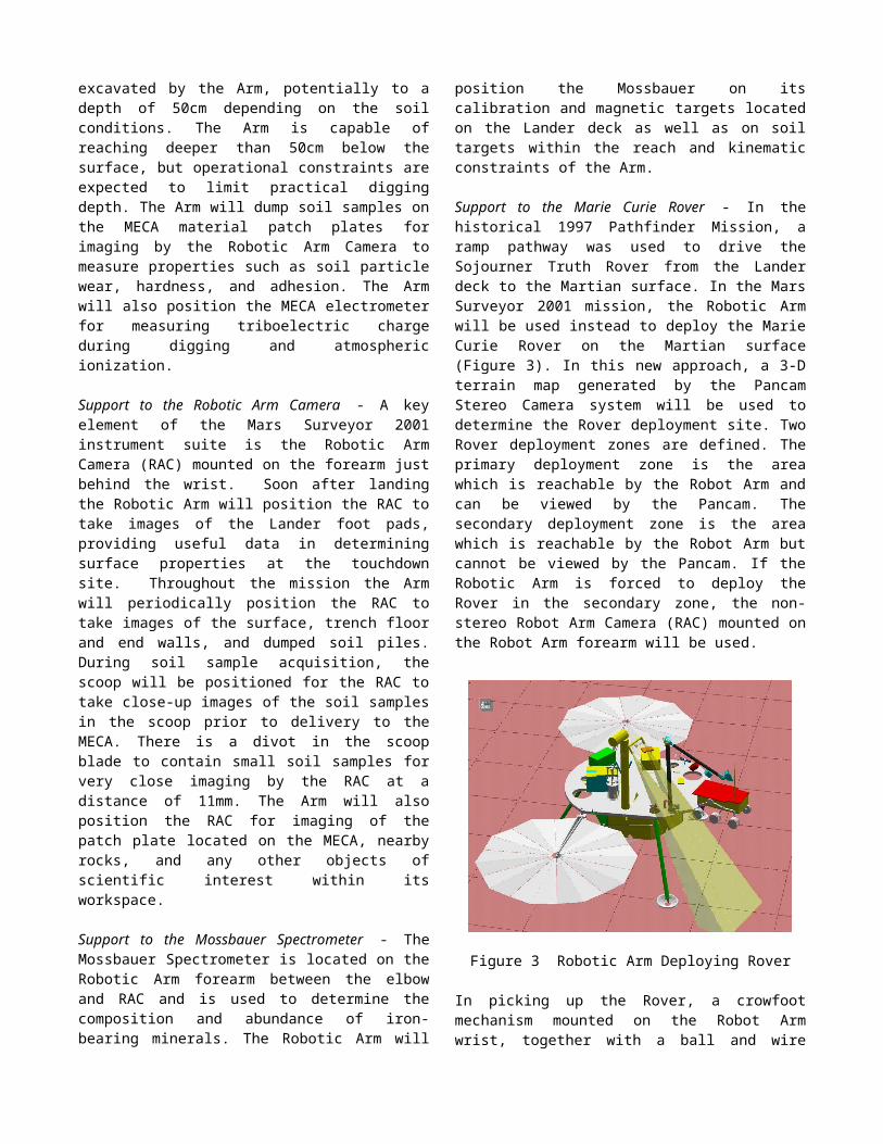
Support to the Marie Curie Rover - In the historical 1997 Pathfinder Mission, a ramp pathway was used to drive the Sojourner Truth Rover from the Lander deck to the Martian surface. In the Mars Surveyor 2001 mission, the Robotic Arm will be used instead to deploy the Marie Curie Rover on the Martian surface (Figure 3). In this new approach, a 3-D terrain map generated by the Pancam Stereo Camera system will be used to determine the Rover deployment site. Two Rover deployment zones are defined. The primary deployment zone is the area which is reachable by the Robot Arm and can be viewed by the Pancam. The secondary deployment zone is the area which is reachable by the Robot Arm but cannot be viewed by the Pancam. If the Robotic Arm is forced to deploy the Rover in the secondary zone, the non-stereo Robot Arm Camera (RAC) mounted on the Robot Arm forearm will be used.
Figure 3 Robotic Arm Deploying Rover
In picking up the Rover, a crowfoot mechanism mounted on the Robot Arm wrist, together with a ball and wire mounted on the top surface of the Rover, will be used. This design allows +/-7 mm Robot Arm positioning error. In order to place the Rover on the Martian surface without bumping into the delicate Rover solar panel surface with the crowfoot, careful studies are necessary since Robot Arm positioning, 3-D terrain map generation, and finding a stable positioning point for a given non-trivial terrain all have limited accuracy. In the visual approach, the Rover will be moved down 3 cm (TBD) at a time, until the crowfoot is disengaged from the ball. Other potential approaches that could reduce the total number of days for
Rover deployment are motor current sensing, short-motor-circuit, and open-motor-circuit approaches. These different approaches will be carefully investigated including thermal-vac tests, examining temperature dependencies.
Robotic Arm as a Science Instrument
During the surface operations of the Mars Surveyor 2001 payload, the Robotic Arm will also be used along with the other Mars Surveyor 2001 instruments to investigate the physical properties of the surface and subsurface materials in the workspace. The primary surface investigation by the Robotic Arm will be the direct measurements of the mechanical properties using motor currents to estimate Arm forces. Additional information will be obtained by judicious planning of Arm operations, such as purposeful placement of excavated soil to observe the angle of repose and the degradation of the pile due to wind erosion. The Robotic Arm workspace activities will be tracked and mapped, and all pertinent Arm calibration and operations data will be archived for future investigations.
Direct measurements by the MECA will provide additional information useful for understanding the physical properties and chemical composition of the surface and subsurface materials. Much of the information about the soil will come from the RAC. The ability of the RAC to provide close-up imaging of material on the tip of the scoop blade at 23 micron resolution is an example of how the data gathered by another instrument is highly dependent on cooperative operation with the Robotic Arm - in this case to deliver an appropriate sample to the RAC near focus viewing zone.
The majority of the physical properties experiments will be planned well in advance of landing. This is because previous in situ missions have left behind a strong history of materials properties investigations. In particular, the Viking Lander mission investigations [4, 7] represent appropriate approaches, which can easily be adapted for use by the Mars Surveyor 2001 payload. Additional information provided by the unique capabilities of the Mars Surveyor 2001 payload will provide new insights in areas previously not possible.
Robotic Arm Description
Hardware -The Mars Surveyor 2001 Robotic Arm is a 4-degree-of-freedom manipulator with a back-hoe design providing motion about shoulder yaw (azimuth) and shoulder, elbow, and wrist pitch. The Arm links are made of a low-mass graphite-epoxy composite. The end effector consists of the following tools: a scoop for digging and soil sample acquisition, secondary blades for scraping, an electrometer for measuring triboelectric charge and atmospheric ionization, and a crowfoot for deploying the Rover.
The joint actuators consist of DC motors with 2-stage speed reduction consisting of a planetary gearhead and harmonic drive (except the wrist, which has a bevel gear at the output of the planetary gear). The actuators are capable
of producing 26, 91, 53, and 10 Newton-meters of torque at the joint output during normal operation for joints 1 through 4, respectively. Peak limits are approximately 50% higher. The amount of force that the Arm can exert at the end effector is configuration dependent, but is typically around 80 N. Braking is achieved by actively shorting the motor leads to slow the motor until magnetic detents capture the rotor. Position sensing is accomplished via non-quadrature optical encoders at the motor shaft and potentiometers at the joint output. Each joint is equipped with a heater (1W for the shoulder and elbow joints and 4W for the wrist joint) and temperature sensor to assure that the motor operation is conducted at or above minimum temperature (208 K). See Table 1 for a summary of the Robotic Arm characteristics.
The RA Electronics (RAE) consists of two PC boards which provides power conditioning; motor and heater drive circuitry; joint encoder counting; A/D conversion of potentiometer voltages, temperature sensor voltages, motor currents, and total heater current. It also provides interface to the Lander Command and Data Handling (C&DH) computer over a 9600 baud serial link. Firmware running on the RAE microprocessor provides for low-level motor command execution to move the joints to the specified positions, heater command execution, A/D calibration, and sensor monitoring. Digital data is updated at 2 ms intervals; analog data is updated at 20 ms intervals.
Software -The RA flight software resides on the Lander Command and Data Handling computer and provides the following functions:
Initialization (load parameter table and state files); Expansion of high-level task commands; Generation of Arm movement trajectories; Control of Arm motion and joint heaters; Setting parameters (e.g., motor current limits) in the
RAE. Reading sensor data and monitoring the Arm status; Fault detection and recovery; Sending Arm sensor data to telemetry.
Table 1 Robotic Arm Parameters
Parameter Value Comment
Degrees of freedom 4 rotary joints - shoulder yaw (azimuth), shoulder pitch, elbow pitch, wrist pitch.
Back-hoe design.
Reach 2-m radius sphere
Max Cartesian velocity 0.07m/sec Configuration dependent.
Mass 5 Kg. Includes electronics (868g).
Materials:
Upper Arm and forearm link Scoop Blade Secondary Blades
Graphite-epoxy tubes.6Al-4V Ti STATungsten Carbide, GC015
Actuators DC motors with 2-stage drive train (planetary gear plus harmonic drive). Wrist has bevel gear for 2
nd stage
instead of harmonic drive.
Accuracy and repeatability 1 cm and 0.5 cm, respectively.
End-effector force capability Configuration dependent; typically 80 Newtons.
Thermal environment:
Non-operating:
Shoulder, upper Arm, elbow Forearm, scoop, wrist
Operating:
Shoulder, upper Arm, elbow Forearm, scoop, wrist
173 K to 308 K.153 K to 308 K
193 K to 308 K168 K to 308 K
Heaters used when necessary to bring actuator temperatures up to 208K before operation.
Scoop volume TBD
Power 42W peak during heavy digging, 15W average during free space motion.
Load dependent. Values include 5W for electronics.
Joint parameters See Table 2.
The Robotic Arm has a full suite of Arm motion commands that provide for coordinated joint motion as well as Cartesian motion of the selected tool [13]. Joint moves can be specified as either absolute moves or relative to the current position. Cartesian moves can be specified as absolute or relative moves with respect to the Mars Surveyor 2001 coordinate frame. The operator can also specify Cartesian motion in the local frame of the currently selected tool (scoop blade, secondary blades, electrometer, RAC, and Mossbauer). The four degrees of freedom for Cartesian position are specified as the three translation coordinates plus the angle that the currently selected tool approach vector makes with the plane of the Lander deck.
Each motion command is broken up into a series of via points which are sent sequentially to the RAE for execution by the firmware. The software control loop sampling
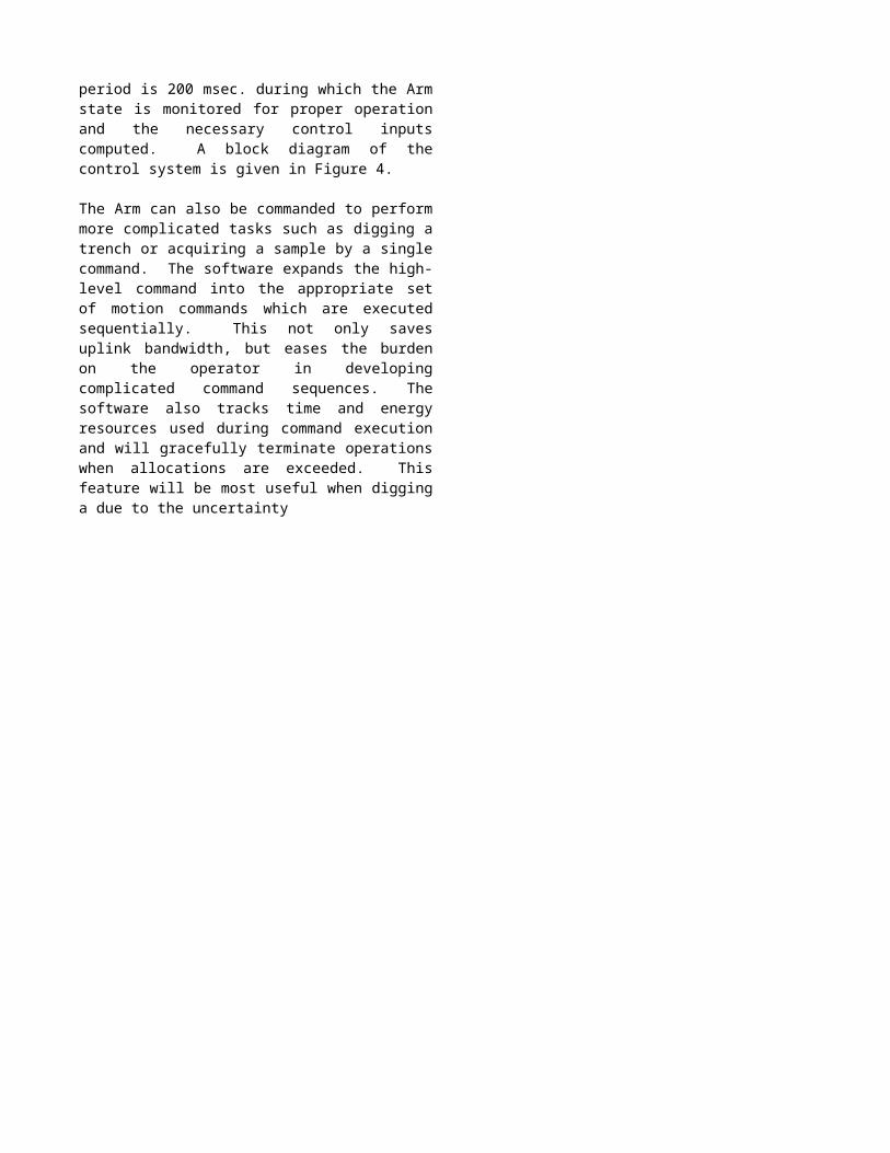
period is 200 msec. during which the Arm state is monitored for proper operation and the necessary control inputs computed. A block diagram of the control system is given in Figure 4.
The Arm can also be commanded to perform more complicated tasks such as digging a trench or acquiring a sample by a single command. The software expands the high-level command into the appropriate set of motion commands which are executed sequentially. This not only saves uplink bandwidth, but eases the burden on the operator in developing complicated command sequences. The software also tracks time and energy resources used during command execution and will gracefully terminate operations when allocations are exceeded. This feature will be most useful when digging a due to the uncertainty
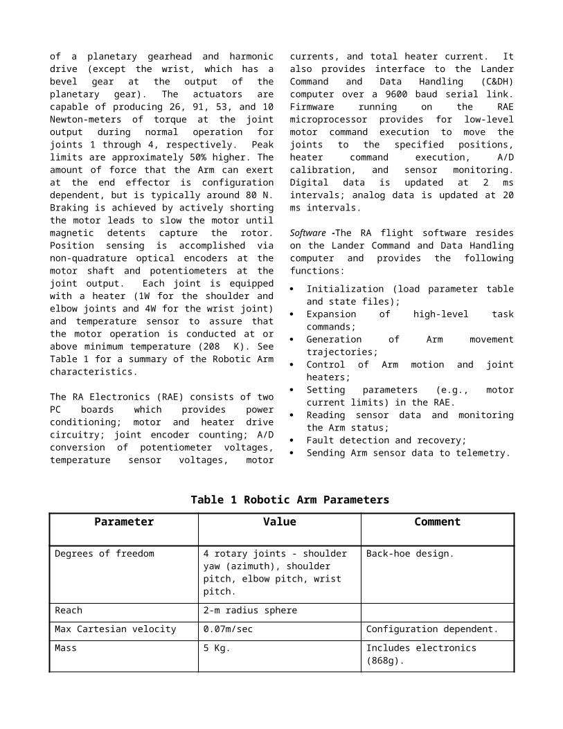
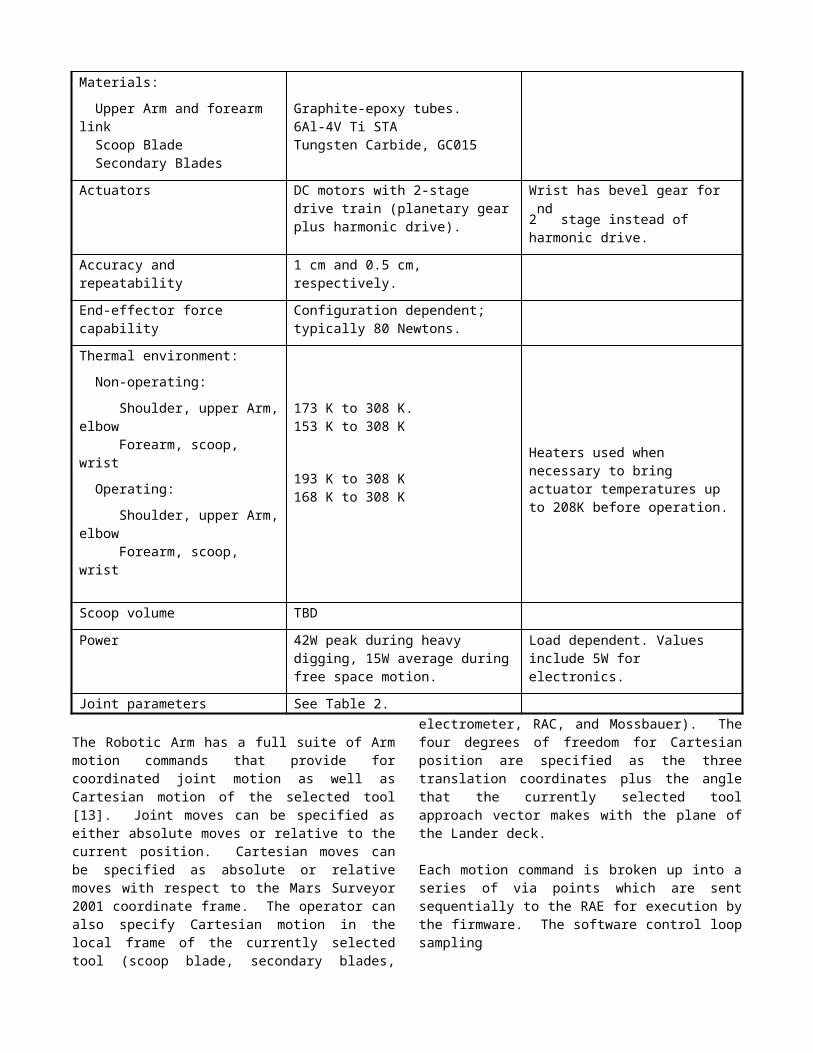
Table 2. Robotic Arm Joint Parameters
Parameter Joint 1 Joint 2 Joint 3 Joint 4 UnitsActuator output torque 26 91 53 10 Newton-meters
Gear ratios 12500 16000 10000 4000
Min angle -134.9 -138.0 -33.6 -20.2 degrees
Max angle 149.9 80.0 231.3 198.6 degrees
Max speed (no load) 2.0 1.5 2.5 6.1 deg/sec
Heaters 1 1 1 4 watts
Figure 4 Robotic Arm Control System
of the soil properties which affect the execution of the dig trench command.
In addition to providing for control of the free-space Arm motions, the software is also capable of executing guarded moves where the Arm will move towards its commanded position until contact is made. This is accomplished by monitoring motor currents and computed joint torques versus preset thresholds. Guarded moves will be employed when positioning the Mossbauer on its targets, acquiring samples, and when digging trenches. Thus, Robotic Arm operation is robust with respect to surface location uncertainty.
To aid in safety and increase autonomy, the Robotic Arm software is capable of detecting and recovering from faults and anomalous events. Faults and events are defined as follows:
Fault - inability to complete a command due to failure of hardware (sensor, actuator, electronics, etc.) or software;
Event - inability to complete a command due to anything other than a fault (e.g., Arm motion impeded due to hard soil).
If a fault or event is detected, the fault or event type is reported in telemetry. Depending on the fault or event detected, the RA software will either attempt to recover from the fault or event or place the Arm in a safe configuration. It is expected that the Robotic Arm will occasionally encounter conditions that impede its motion during digging (a rock in the soil, a patch of ice, etc.). The software has a built-in accommodation algorithm, similar to the algorithm in [1], to compensate for this condition by adjusting the scoop trajectory and, if necessary, dumping the scoop contents and re-executing the digging motion.
Development Testing and Calibration
The Robotic Arm will be extensively tested during development to verify that the design can withstand the harsh environmental conditions expected as well as to characterize the performance of the actuators and to calibrate the sensors and kinematic model of the Arm. Qualification testing included both vibration to simulate launch loads and thermal-vacuum testing to simulate the Martian environment (temperature and pressure).
The performance of the actuators will be evaluated over a temperature range of 183 K to 293 K and expected operating voltages. Data from the characterization are used by the control system to continuously monitor joint torques for use in executing guarded moves, in the accommodation algorithm and to prevent excessive torque from damaging the joints. The joint output torques are computed by first computing the no-load motor currents which are both temperature and voltage dependent and then computing the torque from the actuator torque constant. The no-load motor currents are computed from
Inl = Io + ae-bT
(V/Vmax)
and the joint torques from
Ka(I - Inl)
where Inl is the no-load motor current, Io is the no-load motor current at 293 K, a and b are constants, T is the temperature, V is the applied motor voltage, Vmax is the maximum operating voltage, is the torque, I is the motor current, and Ka is the actuator torque constant. The
constants a, b, and Io are determined from the test data by using a least-squares fit. During the landed mission, a standard set of free-space moves will be periodically executed to monitor actuator performance. In addition, the joint heaters will be operated to characterize the thermal properties of the joints in the Martian environment.
Calibration of the Arm position sensors and kinematic model will be done moving the Arm through a series of poses throughout the workspace and measuring the location of the end effector using a system of highly accurate theodolites. The sensor and kinematic model parameters will then be determined by solving a constrained minimization problem which minimizes the mean error over the measured poses. The kinematic model parameters are based on the method of Denavit and Hartenberg [2].
During digging and soil-mechanics experiments, estimates of forces exerted by the end-effector tools are important data for use in determining soil properties. These estimates can be made from the sensed motor currents, but will be somewhat crude due to unmodeled Arm dynamics and the limited degrees of freedom of the Arm. During digging and soil mechanics experiments, reaction from the soil can exert forces on the end effector which cannot be detected at the Arm joints via the sensed motor currents due to the limited degrees of freedom and the fact that all of the motors are not on at all times during Arm motion. End-effector forces can be estimated from
Fe = JT#
where Fe is the force vector exerted by the end effector,
JT#
is the pseudoinverse of the manipulator Jacobian [10] transpose with the rows associated with the unactuated joints removed, and is the vector of joint torques for the
actuated joints. End-effector forces in the null space of JT
will not appear in the joint torques. The manipulator Jacobian is dependent on Arm configuration and, thus, the transformation to end-effector forces and the null space changes as the joint angles change.
Experimental Investigations
Data acquired as part of the physical properties experiments will come from many sources. A majority of the RA operations will be in support of the primary mission objectives including: digging, dumping, acquiring samples. Although these activities will not be performed specifically to provide materials properties data, by tailoring the operational sequences carefully it will be possible to leverage this data with that from other instruments to gain additional insight. For example, by maintaining a constant dump location for a few hours of operation while digging a trench, a rather sizable conical pile can be obtained. In order for this pile to be useful for observing changes over time, it should be in an isolated area, which necessitates moving the dump location for future digging to another area. This means extra effort in managing the available
workspace as a resource, as well as the additional wear on the actuators for the additional movement, but the supplementary data necessitates the effort.
In addition to the data gained during regular Arm operations, specific materials properties experiments will be performed (see Table 3). Because of the criticality of the efficient operation of the Arm to support the rest of the science objectives (particularly acquiring samples for the MECA) , dedicated materials properties experiments will be done based on available resources. However, even under adverse conditions it should be possible to perform a substantial number of dedicated experiments. The following is a partial list of some of the physical properties experiments that will be conducted:
a) Scoop blade insertion to determine soil penetration resistance.
b) Scraping with the scoop blade and the secondary blades. The cutting ability of the different cutting tools will yield information on the cohesion of the soil. Close-up imaging of wear on the scoop blade will provide grain strength data. If the opportunity is presented, rocks within the workspace will be abraded using the tools on the scoop.
c) Intentionally causing the trench to cave in. By under-cutting the wall of the trench or by using the under side of the scoop to apply pressure at the surface next to the edge of the wall it will be possible to cause a trench wall to cave in under controlled conditions, yielding bearing strength data.
d) Chopping soil samples. The ability of the Arm to repeatedly chop a sample in preparation for MECA delivery will provide cohesion data
e) Shaking the end effector. Because of the flexibility and length of the Arm it is possible to create repeatable agitations to shake loose particles, allowing for insight into particle adhesion.
f) Excavated soil piles. Long term data will be gathered by monitoring the evolution of purposefully placed conical excavated soil piles.
The primary operations tool for commanding the Mars ’01 Robot Arm will be the Web Interface for Telescience (WITS) system. WITS provides target designation from panorama image data, generates command subsequences via programmed macros, simulates arm motion, checks for collisions, computes resources (energy, time, data), and outputs a complete command sequence file for uplink to the Lander.
Data Products
The Robotic Arm subsystem generates two kinds of telemetry - engineering and science. Engineering telemetry consists of current Arm state data which is downlinked at the completion of each Robotic Arm command. Science telemetry consists of detailed sensor data collected every
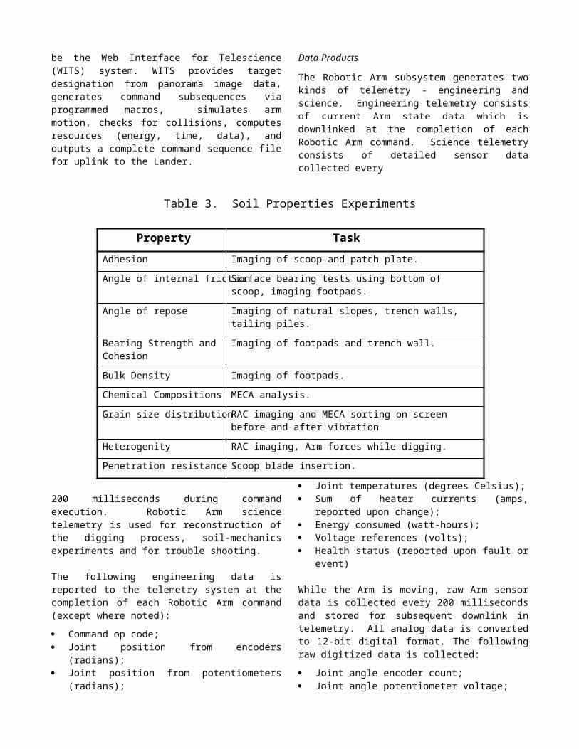
Table 3. Soil Properties Experiments
Property TaskAdhesion Imaging of scoop and patch plate.
Angle of internal friction Surface bearing tests using bottom of scoop, imaging footpads.
Angle of repose Imaging of natural slopes, trench walls, tailing piles.
Bearing Strength and Cohesion Imaging of footpads and trench wall.
Bulk Density Imaging of footpads.
Chemical Compositions MECA analysis.
Grain size distribution RAC imaging and MECA sorting on screen before and after vibration
Heterogenity RAC imaging, Arm forces while digging.
Penetration resistance Scoop blade insertion.
200 milliseconds during command execution. Robotic Arm science telemetry is used for reconstruction of the digging process, soil-mechanics experiments and for trouble shooting.
The following engineering data is reported to the telemetry system at the completion of each Robotic Arm command (except where noted):
Command op code; Joint position from encoders (radians); Joint position from potentiometers (radians); Joint temperatures (degrees Celsius); Sum of heater currents (amps, reported upon change); Energy consumed (watt-hours); Voltage references (volts); Health status (reported upon fault or event)
While the Arm is moving, raw Arm sensor data is collected every 200 milliseconds and stored for subsequent downlink in telemetry. All analog data is converted to 12-bit digital format. The following raw digitized data is collected:
Joint angle encoder count; Joint angle potentiometer voltage; Joint temperatures; Motor currents; Motor voltages; Status word (motor, brakes, and heater state
information) Sum of heater currents; Time.
The Robotic Arm science telemetry will be the most useful for scientific analysis of soil properties during digging and soil-mechanics experiments. The motor currents along
with the reconstructed Arm trajectories will yield information regarding the degree of difficulty of digging in the various soils encountered and of executing the Arm motions during the various soil-mechanics experiments. In addition to the data listed above, detailed history of the Arm state and control variables for the last one minute of
operation is downlinked whenever a fault or event occurs. This will permit reconstruction of the exact sequence of events leading to the anomaly.
The following data will be archived in the Planetary Data System (http:pds.jpl.nasa.gov) for use by the science community:
Position data for the RAC; Joint positions, temperatures and motor currents for
reconstruction of Arm trajectories and joint torques; Calibration report; Experimenter’s notebook.
3. ROVER
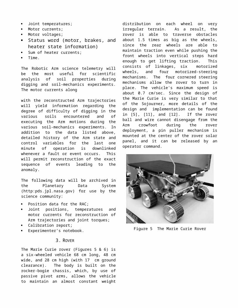
The Marie Curie rover (Figures 5 & 6) is a six-wheeled vehicle 68 cm long, 48 cm wide, and 28 cm high (with 17 cm ground clearance). The body is built on the rocker-bogie chassis, which, by use of passive pivot arms, allows the vehicle to maintain an almost constant weight distribution on each wheel on very irregular terrain. As a result, the rover is able to traverse obstacles about 1.5 times as big as the wheels, since the rear wheels are able to maintain traction even while pushing the front wheels into vertical steps hard enough to get lifting traction. This consists of linkages, six motorized wheels, and four motorized-steering mechanisms. The four cornered steering mechanisms allow the rover to turn in place. The vehicle's maximum speed is about 0.7 cm/sec. Since the design of the Marie Curie is very similar to that of the Sojourner, more details of the design and implementation can be found in [5], [11], and [12]. If the rover ball and wire cannot disengage from the Arm crowfoot during the rover deployment, a pin puller mechanism is mounted at the center of the rover solar panel, and it can be released by an operator command.
Figure 5 The Marie Curie Rover
Figure 6 The Rover Assembly
Electronics
The rover is controlled by an Intel-8085 CPU operating at 2MHz (100KIPS). The on-board electronics are custom designed in order to meet the flight requirements and to fit into a small Warm Electronics Box (WEB). The on-board memory, addressable in 16 Kbyte pages, includes 16 Kbyte rad-hard PROM, 176 Kbyte EEPROM, 64 Kbyte rad-hard RAM and 512 Kbyte RAM. The navigation sensors consist of a rate gyro, 3 accelerometers for sensing the X, Y, and Z axis motion, and 6 wheel encoders for odometry. Articulation sensors include differential and left and right bogey potentiometers. Wheel steering and APXS (Alpha-Proton X-Ray Spectrometer) positions are monitored by 5 potentiometers. All motor currents and the temperatures of vital components are also monitored.
The two front black and white CCD cameras (768 x 484 pixels) provide hazard detection and science/operation imaging. The rear color CCD camera is used for science imaging and APXS target verification. A suite of five infrared laser stripe projectors, coupled with the front CCD cameras, provide the proximity sensing and hazard detection capability for the vehicle. This system operates by locating the image of the laser stripes on a few selected scan lines of the camera images. Deviations of the
detected locations from the nominal flat-terrain values indicate that the terrain is uneven. An array of elevation values is created from the stripe-camera intercepts. Proximity hazards are detected when elevation differences between adjacent points in the array exceed a threshold, or when the difference between the highest and lowest point in the array exceeds a threshold. Other hazards include excessive roll or pitch, or excessive articulation of the chassis, or contact with bump sensors on the front or rear of the vehicle.
A bi-directional UHF radio modem (9600 bits/second) allows the vehicle to transmit telemetry and to receive commands from Earth via the Lander. The vehicle is powered by a 15-watt gas solar panel backed up in case of failure by a non-rechargeable Lithium battery. This battery is also used for nighttime APXS operations.
Rover Navigation
The rover is operated on the basis of a fixed local coordinate frame with origin at the center of the Lander base and the X and Y axes pointed to Martian North and East (right-hand rule), respectively (Martian North is defined by the Lander sun finder). The vehicle's X,Y positions are calculated (at ~2 Hz rate) by integrating its odometer (average of the six wheel encoder counts) with the heading changes produced by the rate gyro. Due to the low processor speed and lack of floating point arithmetic, millimeter (mm) and Binary Angle Measurement (BAM) are used as distance and turn angle units respectively (1 Deg = 182 BAM or 360 Degs = 65,536 BAM). While moving, the vehicle monitors its inclination, articulation, contact sensing, motor and power currents, and temperatures to be sure they did not exceed limit conditions based on risk level settings. Being too close and heading toward Lander conditions are also monitored. The rover periodically sends a heartbeat signal to the Lander at one vehicle-length intervals. In the absence of this communication signal, the vehicle is autonomously backed up half of its length and a communication retry takes place. The rover motion is commanded by one of the following commands: Turn, Move, Go to Waypoint, Find Rock , and Position APXS.
The Turn command in general causes the vehicle to change its heading in place. The four steered wheels are adjusted into their appropriate positions, then the vehicle wheels are turned until the desired heading, indicated by integrating the rate gyro, is met. The rover completes a turn when the gyro heading is in within +/- 1.5 degrees of the desired heading. In case the gyro is disabled, the odometry is used to calculate the heading changes; if both the gyro and odometer are disabled, timing is used in the calculation. The Turn To command causes the vehicle to turn to a specific heading, while the Turn By command causes the vehicle to turn to a relative heading. The Turn At command causes the vehicle to turn so as to point to a specific X,Y position.
The Move command enables the vehicle to move for a specified distance, using only odometry and no hazard

avoidance. This "blind move" is useful when the terrain is clearly seen by the operator (in images from the Lander) and the move is a short one. The Set Steering Position parameter of the Move command determines the arc radius of the move. The rover completes a move once the average six- wheel encoder count exceeds the desired encoder count. Parts of the distance errors are due to the wheel slippage, and they depend on the terrain the vehicle traverses.
The Go to Waypoint command causes the vehicle to traverse to a specified X,Y location. The vehicle drives forward a distance of one wheel radius and stops for laser proximity scanning. A terrain height map is constructed internally from the information provided by the lasers and CCD imagers. If an obstacle is detected on the left, the vehicle will turn right, and visa versa. A flag is set which indicates the direction of the turn, and the vehicle will continue turning by increments until a hazard-free zone at least as wide as the vehicle is detected by the laser scanning system. If the clear zone is wider than the vehicle turning circle, then the rover drives straight ahead far enough to bring the obstacle alongside. Then the rover begins an arc toward the goal point, clears all memory of the hazard avoidance maneuver, and continues. If the clear zone is narrower than the vehicle- turning circle (but wider than the vehicle) then a "thread-the-needle" maneuver is attempted. This maneuver centers the rover on the perpendicular bisector between the two hazards, and moves straight ahead along that line until a zone that is big enough to turn around is detected. Once such a zone is detected, all memory of the maneuver is deleted and the rover begins an arc toward the goal. If an obstacle is encountered prior to detection of a free turning circle, then the rover backs straight out to the point where the thread-the-needle maneuver began, and the rover continues to turn until another hazard-free zone is detected. Arcs toward the goal are calculated to three values: if the rover is already pointed toward the goal (within a small deadband) then the rover goes straight, if the rover heading is outside that deadband but less than about 1 radian, then a large-radius turn (about 2 meters) is begun which turns toward the goal, and if the heading is more than 1 radian from the goal direction, then a short radius turn (about 1 meter) is begun which turns toward the goal. Note that a turn in place maneuver is not used here, since that would cause the rover to become trapped in "box canyons" whereas the present algorithm does not.
The Find Rock command is very similar to the Go to Waypoint command, except that after a hazard is detected at approximately the X,Y position of the waypoint, then the rover centers its heading between the edges of the rock using proximity sensing. If the destination coordinates are reached without any rocks found along the way, a spiral search is performed until the rock is found.
In both Go to Waypoint and Rock Finding commands, the rover reaches its destination when dX * dY < 100 mm 2; dX and dY are distances from the vehicle to its target position in X and Y respectively. In case the rover can not get to its
destination due to an obstacle at the destination, the rover declares a successful command completion when it comes within 500 mm2 of the target destination. The vehicle monitors the progress of the Go to Waypoint and Find Rock commands and enforces a time limit (which is a parameter of the command).
The Position APXS command enables the vehicle to move backward until the APXS sensor head contacts the rock that has been found or until the maximum allowable distance has been reached without contact or time-out.
For every uplink command, the vehicle sends either an acknowledge message or the telemetry collected during execution of the commands, including any error messages. Navigation telemetry in general contains the time tag, the command sequence number, the current X,Y and heading values, steering positions, inclination and articulation values, motor currents, temperatures, and contact and encoder information. In addition, the Go to Waypoint and Find Rock telemetry data also include the obstacle height map provided by the proximity and hazard avoidance mechanism for every 6.5 cm of traverse.The health checks telemetry provides a snapshot of the current status of the vehicle. In addition to almost all of the navigation information, the power supply current and voltage status, individual wheel odometer readings, communication error counts, device fail counts, min/max accelerometer values, motor current values, and average motor currents of the last traversal are reported here. Other rover telemetry data is designed to report data from science, engineering experiments and rover housekeeping utilities.
The rover also has the ability to adjust its position knowledge based on the assessment of the Lander using the Lander Based Autonomous Localization (LBAL) algorithm. For every heartbeat which the rover sends to the Lander during Go to Waypoint or Find Rock command execution, the Lander’s response will be based on whether the LBAL function is active or not. If the Lander’s LBAL function is not active, the rover will continue on with its navigation task. Otherwise, the Lander will request the rover to wait for the Lander to send to the rover the updated position information. The Lander uses the rover position information from the heartbeat message to capture a stereo pair of images with its cameras pointing toward the general area where the rover has stopped. The Lander’s on-board LBAL algorithm will estimate the current rover position based on these images, and will send this new rover position information to the rover for updating. At any time in between commands, the operator can also request the rover to update its position by sending a LBAL request command to the rover. Subsequently, the rover will perform a heartbeat session to get its new position from the Lander.
The Rover Control Station
Human operators using the Rover Control Workstation (RCW) indirectly control the rover. The RCW's customized graphical user interface software provides tools
for the operator to generate commands with parameter checking capabilities and to designate waypoints in a 3-D image display. A command sequence which comprises multiple commands is built based on requests from the scientists, vehicle engineering telemetry, and the end-of-sol stereo images captured by the Lander cameras. The rover 3-D icon shown on the RCW display allows the operator to assess traverse ability by placing the icon over a 3-D Martian terrain image set at any position and orientation. The rover’s current position and heading are also acquired by matching the icon with the rover’s physical position in the stereo images. This capability allows the operator to re-initialize the vehicle’s true position and orientation at the beginning of a sol. In Go to Waypoint designation, the operator specifies the rover destinations by placing the rover 3-D cursor at each waypoint, then clicking the mouse to identify these destinations. The RCW records these waypoints and generates the Go to Waypoint commands automatically. Other commands are generated from operator-specified parameter values, and the command sequence file is created. The accuracy of the designation depends on the distance between the stereo cameras, image resolution, and human designation ability. The overall accuracy of the designation was estimated at about 2 to 3 percent for cross and down ranges and for heading.
The Science Instruments
There will be three science instruments mounted on-board the rover: The Alpha Proton X-ray Spectrometer (APXS), the Mars Experiment on Electrostatic Charging (MEEC), and the Wheel Abrasion Experiment (WAE) instruments.
The APXS instrument [8] is designed to obtain the chemical composition of Martian rocks and soil. The APXS uses three kinds of interactions of the alpha particles from a radioactive source with matter: Rutherford backscattering (alpha mode), nuclear reactions of alpha with some light elements (proton mode), and generation of characteristic x-ray in the sample through ionization by alpha particles (x-ray mode). Three energy spectra obtained from these interactions are recorded in three different channels. In the alpha mode, the APXS can measure all chemical elements, which are heavier than helium. Sensitivity is excellent for light elements such as C, H and O. In the x-ray mode, it measures all elements which are heavier than Na. The instrument includes a sensor head and an electronic box. The sensor head is mounted to the APXS Deployment Mechanism (ADM). Through a command from the operator, the ADM enables the APXS sensor head to be placed closer to but not contacting the experimental rock or soil. The APXS electronic unit serves as an interface between the APXS sensor head and the rover on-board computer system. The electronic unit receives commands from the rover computer and sends appropriate signals to the sensor head. The electronic unit also accumulates APXS sensor head data before sending back to the rover computer. The PIs of this instrument are from the Max-Planck-Institute fur Chemie, Mainz, Germany and from the Enrico Fermi Institute, University of Chicago, Chicago.
The Material Experiment on Electrostatic Charging (MEEC) experiments consists of two components: the Wheel Abrasion Experiment (WAE) and the measurement of the charges during a rover traversal by means of the potential the rover attains during the movement.
The first MEEC component, the WAE instrument [3], Figure 7, is designed to measure how much adhesive and abrasive the Martian dust would be on strips of pure metal attached to one of the rover wheels. Fifteen thin film samples (five each of three different metals) which are attached to the wheel periphery reflect sunlight to a photovoltaic sensor. The wheel rotation enables the presentation of the different sample surfaces to the sensor. The resulting signals are recorded using the rover computer and are interpreted in terms of dust adhesion and abrasive wear.
Figure 7 Reflective wheel (left) for WAE instrument
The second MEEC component consists of a ground reference watchplate mounted at the front left corner of the rover solar panel, and an electronic board for collecting data. A 100-microCurie Americium 241 dot resides on the watchplate and will be used to ionize some of the Martian atmosphere to "ground" itself to Mars. The potential the Marie Curie rover attains during a traversal (or overnight or Martian wind) with respect to the "ground" reference will be measured by the electronic board residing inside the WEB. The potential difference between this dot and the Rover chassis will be measured in terms of nanoAmp current, which flows when the two are connected. This current will be time integrated to acquire a value of electrical charge. This value will then be used together with the measured rover capacitance to estimate the rover electrical potential relative to the charge cloud. The collected data will be converted to a digital format for transmission back to earth for study. The PIs of the MEEC are from the NASA Glen Research Center, Cleveland, Ohio.
4. CONCLUSION
The Mars Surveyor 2001 Robotic Arm is an essential element in carrying out the Mars Surveyor 2001 science experiments. In support of the other instruments, it will dig trenches in the Martian soil, deliver soil samples to the MECA, and position the Mossbauer and the RAC. The
Robotic Arm will also conduct Arm-specific science experiments to collect data relating to soil properties such as periodic imaging of dumped soil piles, surface scraping and soil chopping experiments, compaction tests, insertion of the scoop blade into the soil, scoop shake tests and trench cave-in tests. Key data elements include joint motor currents and trajectories which will be used to estimate end-effector forces during Arm operations. Data from the Robotic Arm support operations and science experiments when combined with data from the other instruments will yield important information on Martian soil properties, providing valuable insight into the history of Mars.
Although the Marie Curie rover is almost identical to the Sojourner rover, which landed on Mars in 1997, many improvements have been made to prepare for the upcoming mission. The rover mechanical and electronics hardware have been refined. The rover’s gyro and accelerometer performances have been improved significantly in terms of accuracy and reliability. The rover software has been
modified to cope with the new requirements in the areas of communication, landing and deployment profile, LBAL, pin puller and MEEC instrument. Some time in January of 2002, the Marie Curie rover will visit a whole new area on Mars in the vicinity of the Lander’s landing site. The rover has the abilities of traversing to designated sites, of examining soil and rocks using its on-board science instruments, and of capturing images of interest sites at close range or from distance. These sites could be far away from the contaminants, which may have been caused by the Lander propulsion system at the landing site. The collective data from the rover will be analyzed and these will bring us up-to-date knowledge at another part of the Martian surface which we have never visited before.
ACKNOWLEDGEMENT
The research described in this paper was carried out by the Jet Propulsion Laboratory, California Institute of Technology, under a contract with the National Aeronautics and Space Administration.
References
[1] Bonitz, R.G. and Hsia, T.C., “Robust Internal Force-tracking Impedance Control for Coordinated Multi-Arm Manipulation - Theory and Experiments”, Proceedings of the 6th International Symposium of Robotics and Manufacturing, 2nd World Automation Congress, May 1996
[2] Denavit, J. and Hartenberg, R.S., “A Kinematic Notations for Lower Pair Mechanisms,” J. Applied Mechan1ics, Vol. 22, pp. 215-221, 1955
[3] Ferguson, D. C., Kolecki, J. C., Siebert, M. W., Wilt, D. M., Matijevic, J. R., “Evidence for Martian electrostatic charging and abrasive wheel wear from the Wheel Abrasion Experiment”, Journal of Geophysical Research, Vol 104. No. E4, pages 8747-8789, April, 25, 1999.
[4] Holmberger, N.A., Faust, R.P. and Holt, H.M., “Viking ‘75 Spacecraft Design and Test, Summary Volume 1”, NASA Reference Publication 1027, pp. 174-180, 1980
[5] Matijevic, J. R., "Mars Pathfinder Microrover - Implementing a Low Cost Planetary Mission Experiment", Proceedings of the Second IAA International Conference on Low Cost Planetary , John Hopkins University, Applied Physics Laboratory, Laurel, Maryland, April 1996.
[6] Mishkin, A. H., J. Morrison, T. Nguyen, H. Stone, B.Cooper, B. Wilcox, "Experiences with Operations and Autonomy of the Mars Pathfinder Microrover", Proceedings of the 1998 IEEE Aerospace Conference, March 21-28, Snowmass at Aspen, Colorado.
[7] Moore, H.J., Hutton, R.E., Clow, G.D. and Spitzer G.E., “Physical Properties of the Surface Materials at the Viking Landing Sites on Mars”, U.S. Geological Survey Professional Paper 1389, 1987
[8] Rider, R., Economu, T., Wanke, H., Turkevich, A., Crisp, J., Buckner, J., Dreibus, G., McSween Jr., H. Y., “The Chemical Composition of Martian Soil and Rocks Returned by the Mobile Alpha Proton X-Ray Spectrometer: Preliminary Results from the X-Ray Mode”, Science, December 1997, Vol. 278 – page 1771-1774.
[9] P. S. Schenker, D. L. Blaney, D. K. Brown, Y. Bar-Cohen, S-S. Lih, R. A. Lindemann, E. D. Paljug, J. T. Slostad, G. K. Tharp, C. E. Tucker, C. J. Voorhees, and C. Weisbin, Jet Propulsion Lab.; E. T. Baumgartner, Mich. Tech. Univ.; R. B. Singer, R. Reid, Univ. of Arizona, "Mars Lander robotics and machine vision capabilities for in situ planetary science," in Intelligent Robots and Computer Vision XIV, SPIE Proc. 2588, Philadelphia, PA, October, 1995.
[10] Spong, M.W. and Vidyasagar, M., “Robot Dynamics and Control”, John Wiley and Sons, pp. 111-119, 1989
[11] Stone, H. W., "Mars Pathfinder Microrover: A Low-Cost, Low-Power Spacecraft", Proceedings of the 1996 AIAA Forum on Advanced Developments in Space Robotics, Madison, WI, August 1996. [12] Stone, H. W., "Design and Control of the MESUR/Pathfinder Microrover", Proceedings of the International Conference on Advanced Robotics, Tokyo, Japan, November 1993.
[13] Taylor, R., “Planning and Execution of Straight-line Manipulator Trajectories”, IBM Journal of Research and Development, Vol. 23, No. 4, pp. 424-436, 1979
Robert Bonitz is currently with the Telerobotics Research and Applications Group at the Jet Propulsion Laboratory where he recently designed and developed the control algorithms and software for the Mars Volatiles and Climate Surveyor Robotic Arm inherited for use by the Mars 2001 Lander Robotic Arm. Previously, he has conducted research in control algorithms for multiple-manipulator robotic systems, robust internal force-based impedance controllers, frameworks for general force decomposition, optimal force control algorithms, and calibration methods for multi-arm robotic systems. He has worked for a variety of industrial companies including Raytheon, TRW, Source 2 International, and GTE. He has a PhD in Electrical Engineering from the University of California, Davis.
Won S. Kim received the Ph.D. degree in electrical engineering and computer sciences from the University of California, Berkeley, in 1986. He has been with the Jet Propulsion Laboratory, Pasadena, CA, since 1988. He received Franklin V. Taylor Award in 1988 IEEE Conference on System, Man, and Cybernetics, and published more than 50 journal and conference papers in the telerobotics area.
Tam Nguyen is a software engineer for the Robotic Vehicles Group at the Jet Propulsion Laboratory, Pasadena, California. Currently, he is the software lead for the Microrover of the 2001 Mars Surveyor Project. Prior to this, he was a Microrover's software team member and a Microrover Downlink Data Analysis team member of the Mars Pathfinder Project. Since 1988, he had developed software and integrated hardware in the areas of motion control, and navigation for several planetary rover research programs. Prior to these programs, he was a software team member of the Telerobotics Research Project, and of the Robotics Technology Test Vehicle Research Project. He was a key software engineer for the Three Axis Acoustic Levitator Project, a physics experiment flown on-board the Shuttle. Nguyen holds a BS in Physics and Chemistry and a MSEE from CSU Long Beach, California.