the manual of timing belt (two-axis drive) design program · download and unzip the installer of...
TRANSCRIPT
2009/7/10The manual of timing belt (two-axis drive) design program
Installation1. Download and unzip the installer of timing belt (two-axis drive) design program.
Installation will be started by double-clicking the installer.Follow the instructions on the display to finish the setup.(See download page of our Homepage for detailed procedure.)
2. The normal installation directory and file name of the program are as the following.Directory C:\Program Files\MITSUBOSHIBELTING\TG2AXES\File name TG2AXES_E.exe
3. If you want to uninstall the program, use the "Add/Remove Programs" utilityin the Microsoft Windows Control Panel.
Table of contents
1. Designing of timing belt1.1 Input process
1.1.1 Input of the use conditions1.1.2 Setting of service factor
1.2 Calculation results
1.3 Adjustment of the layout1.3.1 Change of the pulley diameter1.3.2 Change of the tooth profile1.3.3 Manual designing
1.4 Printing
1.5 Save and load of the calculated data
2. Length calculation program2.1 Composition of the layout
2.1.1 Two-axis drive2.1.2 Three or more axes drive2.1.3 Usage of flat backside pulley2.1.4 Usage of the pulley with swing arm2.1.5 Usage of toothed backside pulley (Double timing belt)
2.2 Adjustment of the layout2.2.1 To rotate the swing arm pulley by clicking the drawing 2.2.2 To rotate the swing arm pulley by assignment of belt length2.2.3 To move pulleys linearly by assignment of belt length2.2.4 To move pulleys freely
2.3 Spring force calculation of swing arm pulley
2.4 Enlarge the drawing
2.5 Printing
2.6 Save and load of the calculated data

1. Designing of timing belt1.1 Input process
The following is an input screen of the timing belt design program.
Figure 1. The Input Screen of the Timing Belt Design Program
1.1.1 Input of the use conditionsFollowing six items are required to input data for the calculation.
①Service factorYou can directly type in service factor to the column. The service factor can auto-configure by clicking on the "See Table" button.(The usage of the service factor subroutine is detailed at section 1.1.2.)
②③Transmission PowerAt column ②, select the unit of the transmission power.Input the value of the transmission power to the column ③.
④Revolutions of the driver pulley⑤Revolutions of the driven pulley
Input both of the columns.
⑥Center DistanceInput the distance between shafts of driver pulley and driven pulley.The unit is "mm".
After inputting all required columns, click on the "Auto Calculation" button.Calculation results will be displayed below "Auto Calculation".In some cases, warning message is displayed and the caution appears at the bottom of calculation results.
①
⑥
⑤④
③ ②
1.1.2 Setting of Service Factor
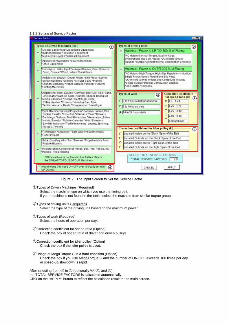
Figure 2. The Input Screen to Set the Service Factor
①Types of Driven Machines (Required)Select the machine type on which you use the timing belt. If your machine is not found in the table, select the machine from similar toqrue group.
②Types of driving units (Required)Select the type of the driving unit based on the maximum power.
③Types of work (Required)Select the hours of operation per day.
④Correction coefficient for speed ratio (Option)Check the box of speed ratio of driver and driven pulleys.
⑤Correction coefficient for idler pulley (Option)Check the box if the idler pulley is used.
⑥Usage of MegaTorque G in a hard condition (Option)Check the box if you use MegaTorque G and the number of ON-OFF exceeds 100 times per dayor speed-up/slowdown is rapid.
After selecting from ① to ③ (optionally ④, ⑤, and ⑥),the TOTAL SERVICE FACTORS is calculated automatically.Click on the "APPLY" button to reflect the calculation result to the main screen.
① ②
③④
⑤
⑥

1.2 Calculation results
Figure 3. Calculation Results of Auto Calculation
Input conditions and click on the "Auto Calculation" button.Calculation results are displayed in the "Auto Calculation" column.In this case, the caution "Width not enough" is shown at the bottom of calculation results.
In these conditions, 332mm width of the timing belt is required.However, the maximum width of standard S5M belt is 250mm, so this layout is inappropriate.
How to change for an appropriate layout is mentioned in the next section.
1.3 Adjustment of the layout1.3.1 Change of the pulley diameter
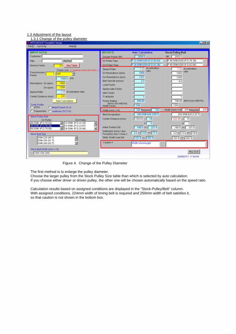
Figure 4. Change of the Pulley Diameter
The first method is to enlarge the pulley diameter.Choose the larger pulley from the Stock Pulley Size table than which is selected by auto calculation.If you choose either driver or driven pulley, the other one will be chosen automatically based on the speed ratio.
Calculation results based on assigned conditions are displayed in the "Stock-Pulley/Belt" column.With assigned conditions, 224mm width of timing belt is required and 250mm width of belt satisfies it, so that caution is not shown in the bottom box.

1.3.2 Change of the tooth profile
Figure 5. Change of the Tooth Profile
The second method is to change the tooth profile.In the auto calculation, S5M tooth profile was chosen.However, maximum belt width of S5M is too narrow for this condition.Now, try to use S8M tooth profile whose maximum belt width is 60mm and can transmit bigger power.
1. Choose STPD in the table of Tooth Profile.2. Choose S8M in the table of Tooth Profile.3. In some cases, a message box and MANUAL Design window are displayed.
How to use the manual design is mentioned in the next section, so close the window now.In this example, the caution "Pulley dia" is shown. (Pulley diameter is too small.)
4. Choose the bigger pulley from the Stock Pulley Size table. (Figure 6)
The caution is not shown after the selection of 30 S8M driven pulley, so this layout is appropriate.
Selectable tooth profiles are shown in the below table.
③
①②
STPD Trapezoidal MegaTorque UrethaneS2M MXL MTS5M(G) T5S3M XL MTS8M(G) T10S5M L MTS14M(G)S8M H MTS8M(U)S14M XH
XXH
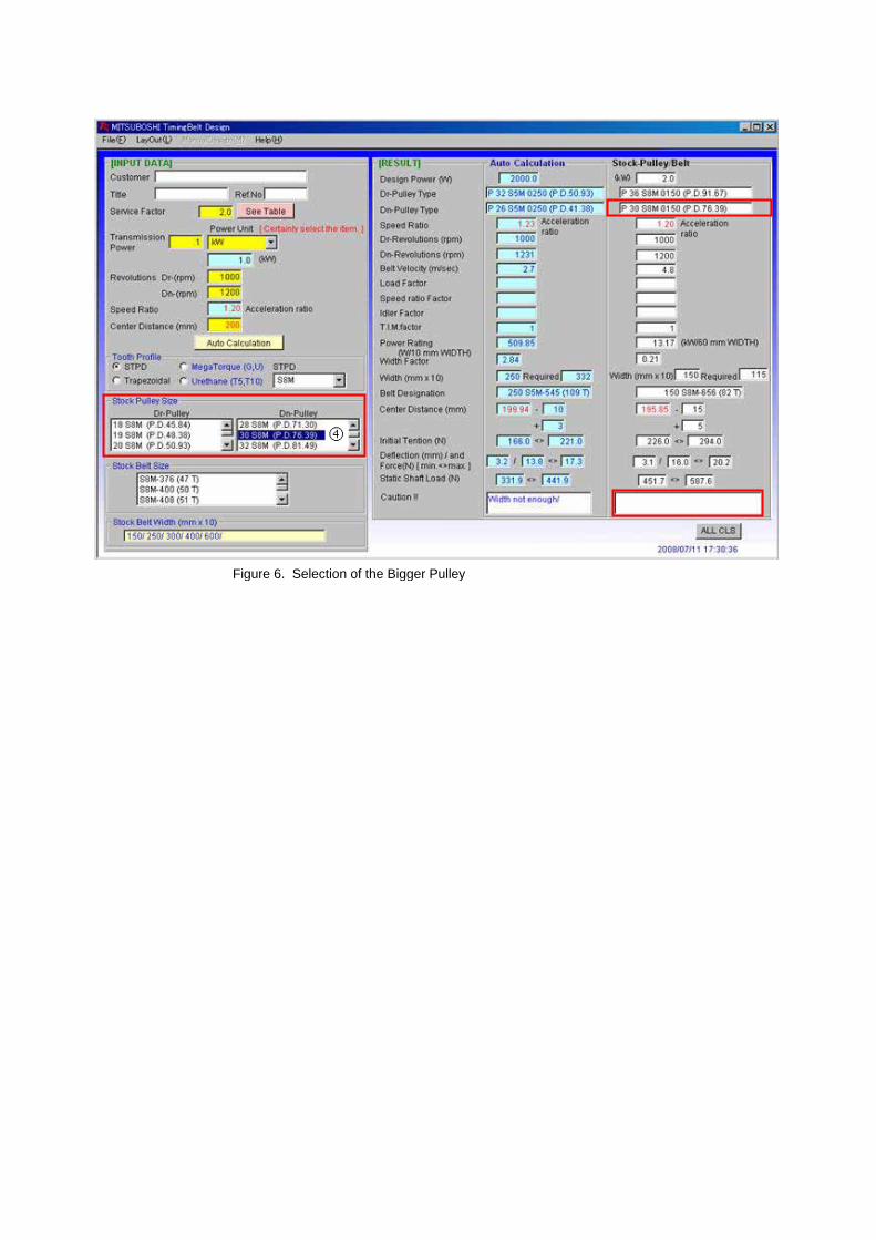
Figure 6. Selection of the Bigger Pulley
④

1.3.3 Manual designing
Figure 7. The Window of Manual Design
The MANUAL Design window is launched by selecting tooth profile from the Tooth Profile table.(The procedure is same as Section 1.3.2 - Step 2)In the manual design, teeth number of driver and driven pulleys, belt width, and center distanceof two pulleys can be assigned.
1. Input the teeth number of driver pulley.2. Input the teeth number of driven pulley.3. Input the ten times value of belt width in mm unit.4. Input the distance between the shafts of two pulleys to the Center Distance column.5. Click on the "Calculate" button.
In the case of the caution is shown, change the conditions to the appropriate value.
・In the manual design, pulleys can't be selected from tables so input the numbers directly to the columnrefer to stock pulley table of the main screen.
・In the manual design, driver or driven pulley will not be selected automatically based on speed ratio,so take care of the speed ratio of "RESULT" column is on-target.
・If you want to change tooth profile, click on the "EXIT" button and reselect the tooth profilein the main screen.

1.4 PrintingSelect "File">"Print" from Menu Bar.
In the case of both "Auto Calculation" and "Stock-Pulley/Belt" are displayed, only the results of "Stock-Pulley/Belt" will be printed.If you want to print out the results of "Auto Calculation", click on the "Auto Calculation" button and thenselect the "Print" from Menu Bar.
The results of manual design also can be printed from the Menu Bar.
1.5 Save and load of the calculation dataYou can save the calculation data by selecting File menu from Menu Bar.
Save Data is saved in original file form *.tgc extension. Old saved data will disappear.
Save as Data is saved in original file form *.tgc extension. You can create a new saved file.
CSV Save as Data is saved in CSV file extension *.csv.Saved file can be opened by Microsoft Excel, etc..
TEXT Save as Data is saved in text file extension *.txt.Saved file can be opened by Memo Pad, Microsoft Word, etc..
You can load the saved data by selecting "File">"Open" from Menu Bar.
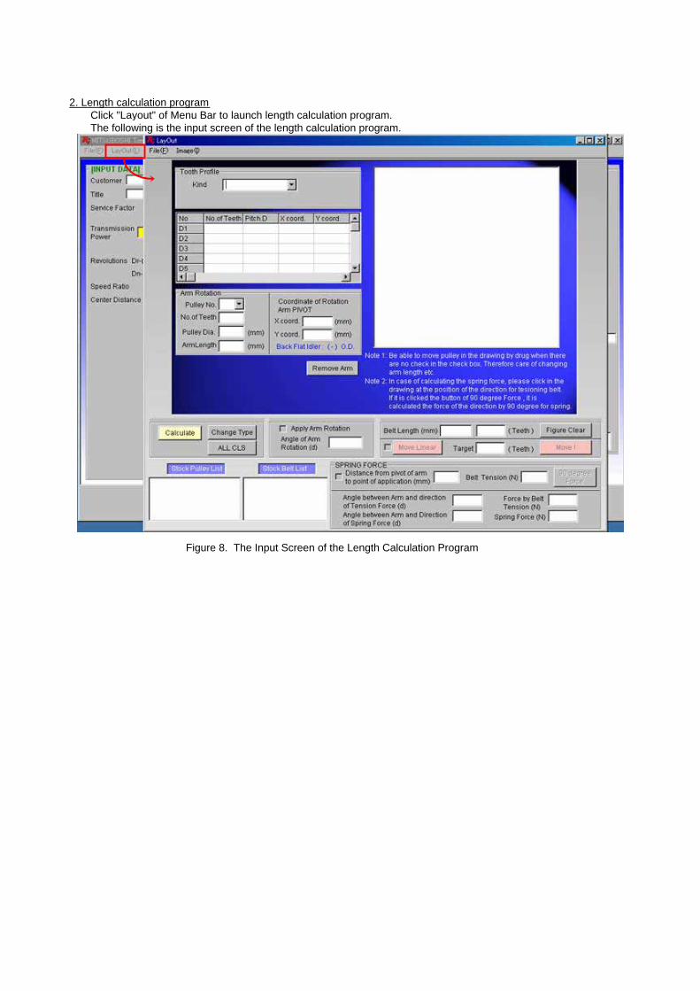
2. Length calculation programClick "Layout" of Menu Bar to launch length calculation program.The following is the input screen of the length calculation program.
Figure 8. The Input Screen of the Length Calculation Program

2.1 Composition of the layout2.1.1 Two-axis drive
Figure 9. Example of Two-axis Drive Layout
At first, select the tooth profile.In this example, S5M-Single is selected.Selectable tooth profiles are shown in the below table.
In the next step, input data to D1 row (the driver pulley) and D2 row (the driven pulley).In ”No. of Teeth" column, input the teeth number of each pulley. Pitch diameter is calculated automatically.(You can also select the pulley teeth number from the Stock Pulley List bottom of the window.)In X coord. and Y coord. columns, input coordinates of the center of pulleys.After you input all data, click on the "Calculate" button to display layout drawing and Belt Length.
The driver pulley is shown in red, and the driven pulley is shown in yellow.Belt length is represented by two units, "mm" and "Teeth".
Trapezoidal STPD Urethane MegaTorqueMXL S2M T5 MTS5M(G)XL S3M T10 MTS8M(G)L S5M MTS14M(G)H S8M MTS8M(U)
XH S14MXXH

2.1.2 Three or more axes drive
Figure 10. Example of Three-axis Drive Layout
This program is for the drive design with three or more axes drive layout. In such cases, first input the data of the driver pulley and then move clockwise (right-handed). In "No. of Teeth" column, input the teeth number of each pulley. Pitch diameter is calculated automatically.In X coord. and Y coord. columns, input coordinates of the center of pulleys.After you input all data, click on the "Calculate" button to display layout drawing and Belt Length.
The driver pulley is shown in red, and other pulleys are shown in yellow.Belt length is represented by two units, "mm" and "Teeth".(This layout is inappropriate because the teeth number is not integer. The adjustment of the layout is detailed in the section 2.2.)
By using scroll bar at the bottom of the table, "TIM", "ArcAngle", "SpanL", and "C.D." will be found. TIM : Teeth in Meshing
The number of teeth in meshing.ArcAngle : Arc Angle
Contact angle between the pulley and the belt.SpanL : Span Length
The belt length between the points where the belt and pulleys contact.C.D. : Center Distance
The distance between the center of pulleys.It is possible to use the scroll bar to see these informations in most cases.
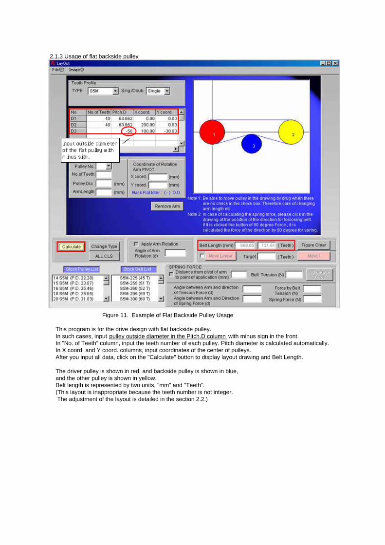
2.1.3 Usage of flat backside pulley
Figure 11. Example of Flat Backside Pulley Usage
This program is for the drive design with flat backside pulley. In such cases, input pulley outside diameter in the Pitch.D column with minus sign in the front.In "No. of Teeth" column, input the teeth number of each pulley. Pitch diameter is calculated automatically.In X coord. and Y coord. columns, input coordinates of the center of pulleys.After you input all data, click on the "Calculate" button to display layout drawing and Belt Length.
The driver pulley is shown in red, and backside pulley is shown in blue, and the other pulley is shown in yellow.Belt length is represented by two units, "mm" and "Teeth".(This layout is inappropriate because the teeth number is not integer. The adjustment of the layout is detailed in the section 2.2.)
Input outside diameterof the flat pulley withminus sign.
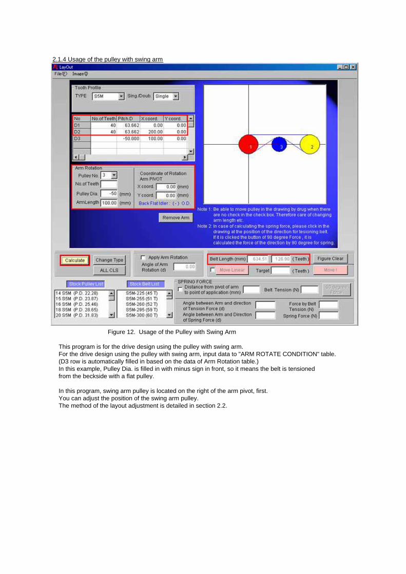
2.1.4 Usage of the pulley with swing arm
Figure 12. Usage of the Pulley with Swing Arm
This program is for the drive design using the pulley with swing arm. For the drive design using the pulley with swing arm, input data to "ARM ROTATE CONDITION" table. (D3 row is automatically filled in based on the data of Arm Rotation table.)In this example, Pulley Dia. is filled in with minus sign in front, so it means the belt is tensioned from the beckside with a flat pulley.
In this program, swing arm pulley is located on the right of the arm pivot, first.You can adjust the position of the swing arm pulley.The method of the layout adjustment is detailed in section 2.2.

2.1.5 Usage of toothed backside pulley (Double timing belt)
Figure 13. Example of Toothed Backside Pulley Usage
This program is for the drive design with toothed backside pulley.
To use toothed backside pulley, double timing belt should be selected, first.In the case of you selected single timing belt, click on the "ALL CLS" button to delete all input data and reselect double timing belt from the tooth profile table.
In "No. of Teeth" column, input the teeth number of each pulley. Pitch diameter is calculated automatically.To use toothed backside pulley, input pulley teeth number in the No.of Teeth column with minus sign in the front.In X coord. and Y coord. columns, input coordinates of the center of pulleys.After you input all data, click on the "Calculate" button to display layout drawing and Belt Length.
The driver pulley is shown in red, and toothed backside pulley is shown in blue, and the other pulley is shown in yellow.Belt length is represented by two units, "mm" and "Teeth".(This layout is inappropriate because the teeth number is not integer. The adjustment of the layout is detailed in the section 2.2.)
Input teeth number of thetoothed backside pulleywith minus sign.

2.2 Adjustment of the layoutThis section explains how to adjust the layout.
2.2.1 To rotate the swing arm pulley by clicking the drawing
Figure 14. To Rotate the Swing Arm Pulley by Clicking the Drawing
The first method is to rotate the swing arm pulley by clicking the drawing.The procedure is following.
1. Click and check the box of "Apply Arm Rotation".2. Click on the drawing where you want to rorate the swing arm pulley.3. Click on the "Yes" button of the message box.
The swing arm pulley is rotated to the position where you pointed andAngle of Arm Rotation and Belt Length will be changed. (Figure 15)
①
②
③

Figure 15. The Result of Rotating the Swing Arm Pulley by Clicking the Drawing

2.2.2 To rotate the swing arm pulley by assigning the belt length
Figure 16. To Rotate the Swing Arm Pulley by Assignment of Belt Length
The second method is to rotate the swing arm pulley by assigning the belt length.
1. Click and check the box of "Apply Arm Rotation".2. Input the target belt length to the "Target" box.
You can also select the target belt length from the Stock Belt List.(By clicking on the stock belt size, the box of "Target" will be filled in automatically.)
3. Click on the "Calculate" button.
The swing arm pulley is rotated to the position where belt length becomes the assigned length. Angle of Arm Rotation and Belt Length will be changed. (Figure 17)
The initial (D) of the stock belt list reveals that double timing belt is available.
①
②
③

Figure 17. The result of Rotating the Swing Arm Pulley by Assigning the Belt Length
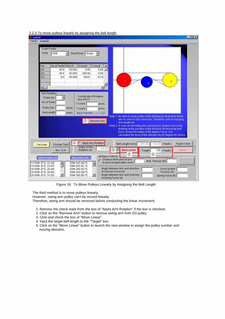
2.2.3 To move pulleys linearly by assigning the belt length
Figure 18. To Move Pulleys Linearly by Assigning the Belt Length
The third method is to move pulleys linearly.However, swing arm pulley can't be moved linearly.Therefore, swing arm should be removed before conducting the linear movement.
1. Remove the check mark from the box of "Apply Arm Rotation" if the box is checked.2. Click on the "Remove Arm" button to remove swing arm from D3 pulley.3. Click and check the box of "Move Linear".4. Input the target belt length to the "Target" box.5. Click on the "Move Linear" button to launch the new window to assign the pulley number and
moving direction.
⑤
②
①
③
④
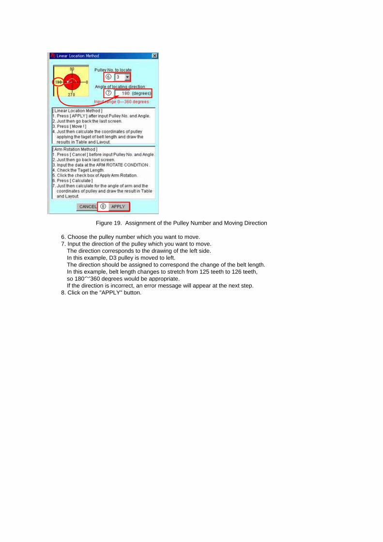
Figure 19. Assignment of the Pulley Number and Moving Direction
6. Choose the pulley number which you want to move.7. Input the direction of the pulley which you want to move.
The direction corresponds to the drawing of the left side. In this example, D3 pulley is moved to left.The direction should be assigned to correspond the change of the belt length. In this example, belt length changes to stretch from 125 teeth to 126 teeth,so 180~360 degrees would be appropriate.If the direction is incorrect, an error message will appear at the next step.
8. Click on the "APPLY" button.
⑥
⑦
⑧
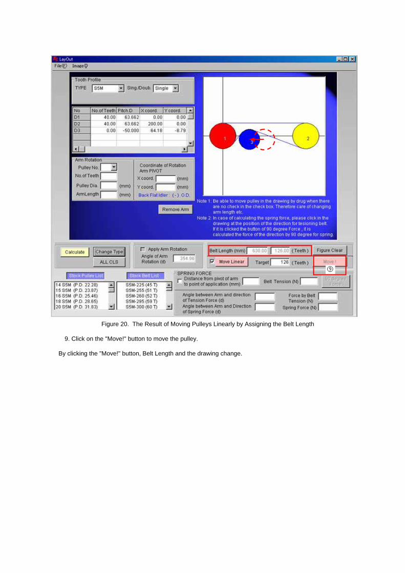
Figure 20. The Result of Moving Pulleys Linearly by Assigning the Belt Length
9. Click on the "Move!" button to move the pulley.
By clicking the "Move!" button, Belt Length and the drawing change.
⑨
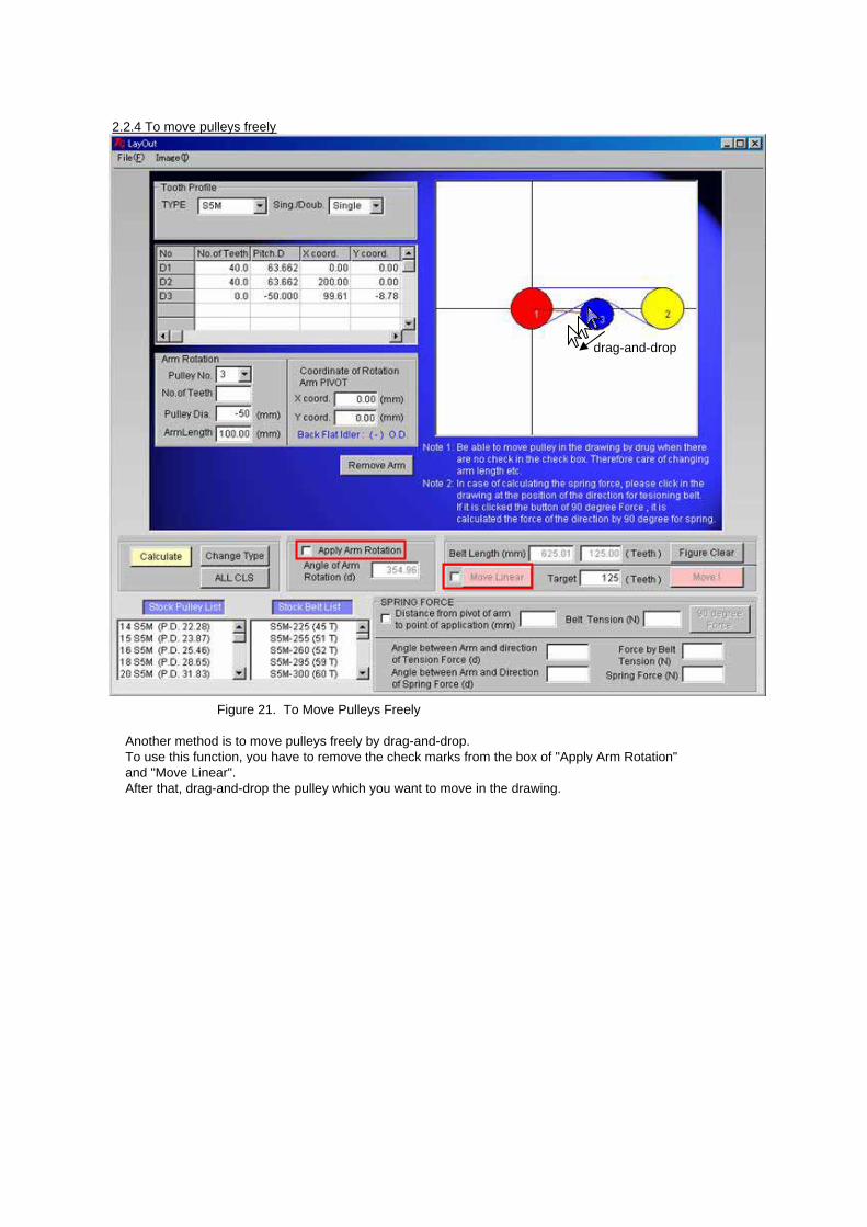
2.2.4 To move pulleys freely
Figure 21. To Move Pulleys Freely
Another method is to move pulleys freely by drag-and-drop.To use this function, you have to remove the check marks from the box of "Apply Arm Rotation" and "Move Linear". After that, drag-and-drop the pulley which you want to move in the drawing.
drag-and-drop
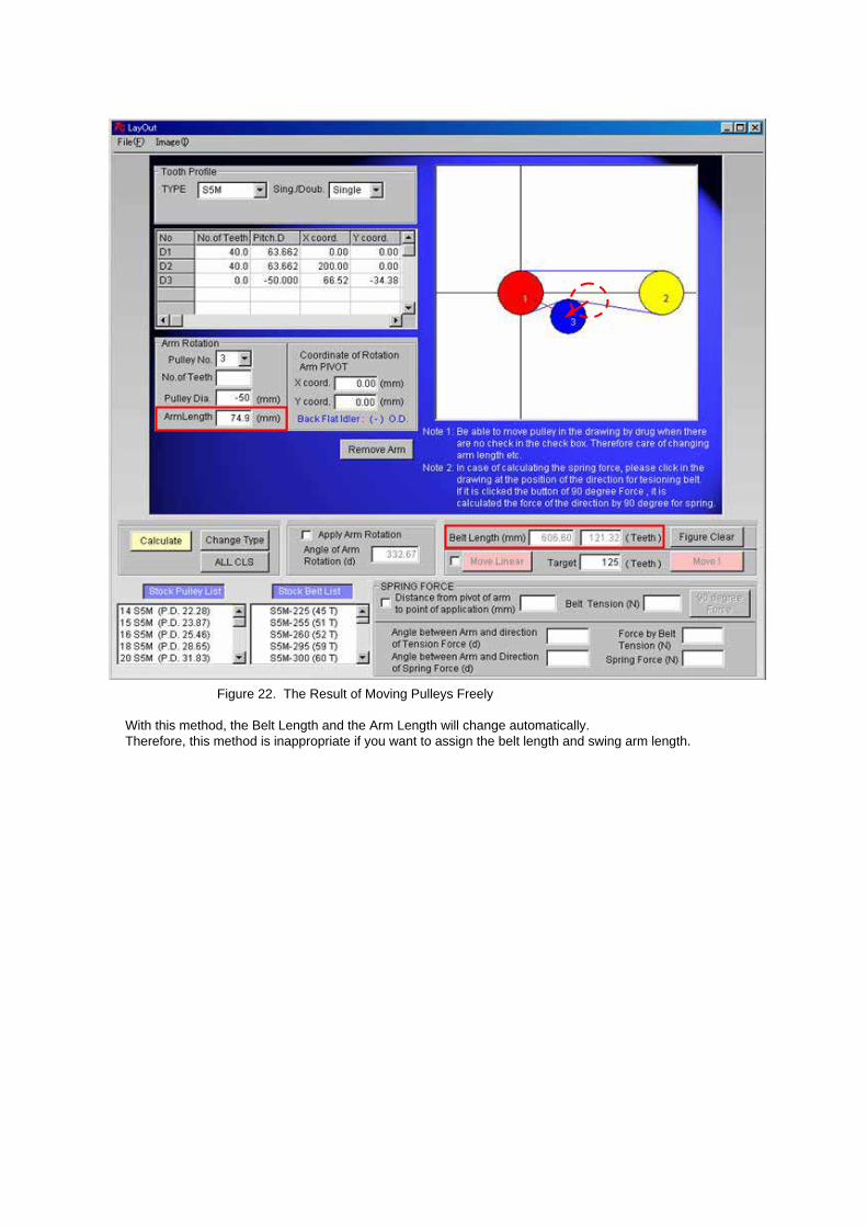
Figure 22. The Result of Moving Pulleys Freely
With this method, the Belt Length and the Arm Length will change automatically.Therefore, this method is inappropriate if you want to assign the belt length and swing arm length.
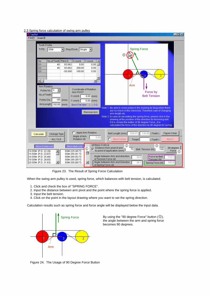
2.3 Spring force calculation of swing arm pulley
Figure 23. The Result of Spring Force Calculation
When the swing arm pulley is used, spring force, which balances with belt tension, is calculated.
1. Click and check the box of "SPRING FORCE".2. Input the distance between arm pivot and the point where the spring force is applied. 3. Input the belt tension.4. Click on the point in the layout drawing where you want to set the spring direction.
Calculation results such as spring force and force angle will be displayed below the input data.
By using the "90 degree Force" button (⑤),the angle between the arm and spring force becomes 90 degrees.
Figure 24. The Usage of 90 Degree Force Button
①② ③
④
⑤
Spring Force
Arm
Spring Force
Force byBelt Tension
Arm
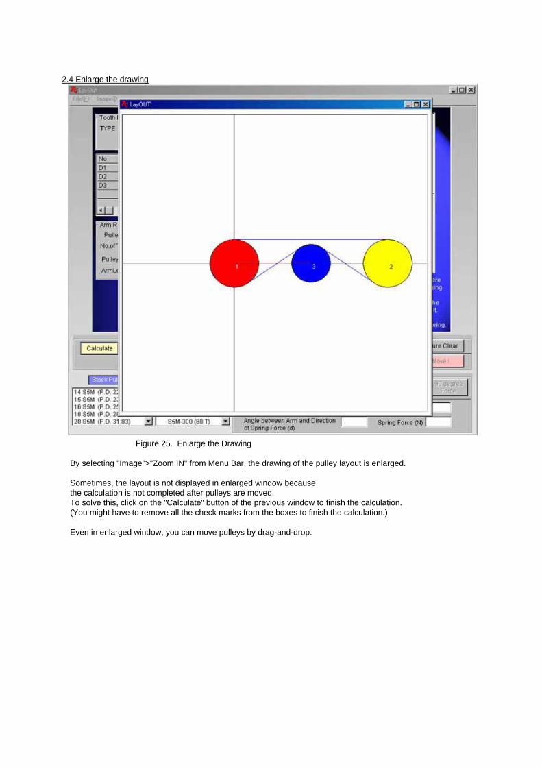
2.4 Enlarge the drawing
Figure 25. Enlarge the Drawing
By selecting "Image">"Zoom IN" from Menu Bar, the drawing of the pulley layout is enlarged.
Sometimes, the layout is not displayed in enlarged window becausethe calculation is not completed after pulleys are moved. To solve this, click on the "Calculate" button of the previous window to finish the calculation.(You might have to remove all the check marks from the boxes to finish the calculation.)
Even in enlarged window, you can move pulleys by drag-and-drop.

2.5 PrintingSelect "File">"Print" from Menu Bar.
2.6 Save and load of the calculated dataYou can save the calculated data by selecting File menu from Menu Bar.
Save as Data is saved in original file form extension *.tcl.You can create a new saved file.
Save Data is saved in original file form extension *.tcl.Old saved data will disappear.
dxf Save as Data is saved in DXF file extension *.dxf.Saved file can be opened by the application which can deal with CAD data.
CSV Save as Data is saved in CSV file extension *.csv.Saved file can be opened by Microsoft Excel, etc..
Text Save as Data is saved in text file extension *.txt.Saved file can be opened by Memo Pad, Microsoft Word, etc..
You can load the saved data by selecting "File">"Open" from Menu Bar.