the magazine of the global bbr network of experts
TRANSCRIPT
Edition 14 | 2020www.bbrnetwork.com
T H E M A G A Z I N E O F T H E G L O B A L B B R N E T W O R K O F E X P E R T S
60TH ANNIVERSARY OF BBR STAY CABLE TECHNOLOGY
Staying strong for six decades
SHAPING THE SINGAPORE SKYLINE
BBR technology & techniques for high-rise buildings
SPARKLING AWARDS FOR BRIDGE
UK’s Mersey Gateway Bridge wins multiple awards
NEW INTERNATIONAL BENCHMARK IN GT TECHNOLOGY
BBR VT CONA CMG strand ground anchors
WORLD RECORD CAPACITY ANCHORS
Installation of largest anchors for dam project

The BBR Network is recognized as the leading group of specialized
engineering contractors in the field of post-tensioning, stay cable
and related construction engineering. The innovation and technical
excellence, brought together in 1944 by its three Swiss founders –
Antonio Brandestini, Max Birkenmaier and Mirko Robin Ros –
continues, more than 75 years later, in that same ethos and
enterprising style. From its Technical Headquarters and Business
Development Centre in Switzerland, the BBR Network reaches out
around the globe and has at its disposal some of the most talented
engineers and technicians, as well as the very latest internationally
approved technology.
THE GLOBAL BBR NETWORK
Within the Global BBR Network, established traditions and strong
local roots are combined with the latest thinking and leading edge
technology. BBR grants each local BBR Network Member access to
the latest technical knowledge and resources – and facilitates the
exchange of information on a broad scale and within international
partnering alliances. Such global alliances and co-operations create
local competitive advantages in dealing with, for example, efficient
tendering, availability of specialists and specialized equipment or
transfer of technical know-how.
ACTIVITIES OF THE NETWORK
All BBR Network Members are well-respected within their local
business communities and have built strong connections in their
respective regions. They are all structured differently to suit the local
market and offer a variety of construction services, in addition to the
traditional core business of post-tensioning.
BBR TECHNOLOGIES & BRANDS
BBR technologies have been applied to a vast array of different
structures – such as bridges, buildings, cryogenic LNG tanks, dams,
marine structures, nuclear power stations, retaining walls, tanks,
silos, towers, tunnels, wastewater treatment plants, water reservoirs
and wind farms. The BBRTM brands and trademarks – CONA®,
BBRV®, HiAm®, HiEx, DINA®, SWIF®, BBR E-Trace and CONNÆCT® –
are recognized worldwide. The BBR Network has a track record of
excellence and innovative approaches – with thousands of structures
built using BBR technologies. While BBR’s history goes back over
75 years, the BBR Network is focused on constructing the future –
with professionalism, innovation and the very latest technology.
BBR VT International Ltd is the Technical Headquarters and Business Development Centre of
the BBR Network located in Switzerland. The shareholders of BBR VT International Ltd are BBR
Holding Ltd (Switzerland), a subsidiary of the Tectus Group (Switzerland) and KB Spennteknikk
AS (Norway), a subsidiary of the KB Group (Norway).
02 CONNÆCT | Edition 14

Marcel PoserChairman, BBR VT International Ltd
José Manuel IllescasVice Chairman, BBR VT International Ltd
Through the pages of the 2020 edition of the BBR Network’s
magazine CONNÆCT, we are delighted to share with you
some further insights into the latest BBR construction
technology and the achievements of our international family,
the BBR Network.
Without a doubt, BBR technology and techniques are contributing towards
harnessing greater productivity for the construction industry. Among
the features in the Portfolio section, you can read about how BBR post-
tensioning and techniques enabled a reduced cycle time for bridge launching
in Australia and about high-rise buildings in Singapore and New Zealand,
as well as an innovative ‘energy positive’ building in Norway.
There are also articles on the strengthening of several dams where the
world’s largest capacity ground anchors are being deployed. The recently
introduced geotechnical BBR Bar range is also proving popular around the
world – the BBR H Bar system is being used for a bridge in the Philippines
and a huge dam in Turkey.
In a special feature celebrating the 60th Anniversary of BBR stay cable
technology, you can also discover how, having created a number of ‘world
firsts’, we have continued to refine and adapt our stay cable technology.
Like us, you will surely conclude that the BBR HiAm CONA stay cable system
is simply the best product on the international market place today.
The Technology section includes a major feature about the BBR VT CONA
CMG strand ground anchor system which sets a new benchmark for the
corrosion protection of strand ground anchors. Last but not least, don’t
miss the articles about automating construction with MSS technologies
and developments in digital construction.
Over recent years, the BBR family has grown significantly – the range of
BBR technologies has expanded and the BBR Network has also extended
its reach into new territories. Maybe you will be reading this and consider-
ing joining the BBR Network. If you share our passion for the highest level
of customer service and the finest construction technology, we would be
pleased to hear from you!
Sharing passion & productivity
Edition 14 | 2020www.bbrnetwork.com
T H E M A G A Z I N E O F T H E G L O B A L B B R N E T W O R K O F E X P E R T S
60TH ANNIVERSARY OF BBR STAY CABLE TECHNOLOGY
Staying strong for
six decades
SHAPING THE SINGAPORE SKYLINE
BBR technology & techniques for
high-rise buildings
SPARKLING AWARDS FOR BRIDGE
UK’s Mersey Gateway Bridge wins multiple awards
NEW INTERNATIONAL BENCHMARK IN GT TECHNOLOGY
BBR VT CONA CMG
strand ground anchors
WORLD RECORD CAPACITY ANCHORS
Installation of largest anchors for dam project
www.bbrnetwork.com 03

Contents
12
15 48
34
PORTFOLIO
15 BRIDGES
Sparkling awards for bridge
Technical expertise overcomes challenges
Span closure for record-breaking bridge
Talent for increasing productivity
River crossing with latest BBR technology
Bridging the crossroads of Europe
Bridge quintet in Norway
34 BUILDINGS
Shaping the Singapore skyline
Rise-and-rise of elevated PT
The Green Diamond
Great innings for BBR
Meeting demands of dynamic growth
Double landmark
TALKING BBR
06 BUSINESS REVIEW Remaining relevant,
comprehensive
& value-adding
09 NEWS HIGHLIGHTS Events & news from around
the BBR Network
12 ANNUAL BBR GLOBAL CONFERENCE, ZURICH, SWITZERLAND Business and cultural exchange
14 PERSPECTIVE Creating visions of success
48 STAY CABLES
Staying strong for six decades
Making new connections
Extra special bridge structures
Secrets of success
Orchestrated spans
Industrial strength technology
Standing the test of time
60 SPECIAL APPLICATIONS
World record capacity anchors
Harnessing the wind
New apartments get the PRESSS treatment
BBR Bars take the load
Tanking up for LNG
Specialist techniques for water
72 MRR
New life for old bridges
Safe storage for seeds
Putting buildings on the level
Renewed strength for vital infrastructure
Supporting a downtown transformation
04 CONNÆCT | Edition 14
06

Editorial, sources and references
EDITORIAL OFFICEBBR VT International Ltd
Technical Headquarters and Business Development Centre, Switzerland
www.bbrnetwork.com
EDITORJane Sandy
CONTRIBUTING EDITORMarco Zucconi
DESIGNERJenny Chillingworth
PUBLISHERBBR VT International Ltd
Every effort is made to ensure that the content of this edition is accurate
but the publisher accepts no responsibility for effects arising therefrom.
p-ISSN 1664-6606
e-ISSN 1664-6614
© BBR VT International Ltd 2020
CONTRIBUTORSMohamad Al-Shal, Mohammed Ashour, Victor Barray, Efe Bayram, Derek
Bilby, Paul Blundell, Sarah Brown, Daniel Cuerdo, Antoine Dupré, Zerrin
Eren, Haifeng Fan, Paul Greenacre, Kadir Serden Hekimoglu, Peter Higgins,
Warwick Ironmonger, Kristoffer Kalland, Sean Kelly, Ahmet Ferit Kutay,
Murat Kutay, Jonas Larsson, Hans Erik Larsson, Dickson Liew, Lee Chuen
Lin, Juan Manuel Linero, Tomislav Lozancic, Mahesh Nayak, Juan Maier,
Behzad Manshadi, Mark Martin, Valentina Mihajlovic, Steve Mutton, Rusper
Patel, Sam Pearce, Anna Pietruszka, Vince Ponzio, Marcel Poser, Bojan
Radosavljevic, Zuhair Rawi, Mark Sinclair, Rey Singh, Stig Solbjør, Cezary
Sternicki, Marc Stewart, Pawel Surman, John Taraldsen, Bruno
Valsangiacomo, Xiaomeng Wang, Paul Wymer, Janelle Yeo.
SOURCES AND REFERENCESFront cover image: The dramatically beautiful RAMA VIII Bridge in
Bangkok, Thailand is one of the 430+ stay cable projects carried out by
the BBR Network in the last six decades. See page 48 for the feature
celebrating 60 years of BBR stay cable technology.
Portfolio sectionSparkling awards for bridge: https://www.iabse.org;
http://www.merseygateway.co.uk
Span closure for record-breaking bridge: http://www.gov.me
Bridging the crossroads of Europe: https://www.d4r7.com;
https://www.roadtraffic-technology.com
Bridge quintet in Norway: https://www.vegvesen.no;
https://www.banenor.no
Shaping the Singapore skyline: https://global.ctbuh.org
The Green Diamond: https://snohetta.com, https://www.powerhouse.no,
https://architizer.com
Making new connections: http://www.romfilatelia.ro
Standing the test of time: https://city-tourist.de;
https://www.sueddeutsche.de; http://www.arcaro.org;
IABSE congress report (1972): Das Olympiadach in München, by Jörg
Schlaich, H. Altmann, R. Bergermann, K. Gabriel, K. Horstkötter, K.
Kleinhanss, P. Linhart, G. Mayr, J. Noesgen, U. Otto, H. Schmidt,
Ingenieurbüro Leonhardt und Andrä, Stuttgart, Germany.
Safe storage for seeds: https://www.croptrust.org;
https://www.theguardian.com; https://www.independent.co.uk
Renewed strength for vital infrastructure: https://www.tellerreport.com;
https://structurae.net; https://fr.wikipedia.org
Technology section
The dawn of digital fabrication: http://dfabhouse.ch;
Die Parkhaus-Brücke über die Rämistrasse in Zürich by 0. Liechti, W.
Glanzmann und J. Schneider, Bauingenieure, Zürich, published in
Schweizerische Bauzeitung 20 July 1967;
Modular construction: From projects to products, by Nick Bertram, Steffen
Fuchs, Jan Mischke, Robert Palter, Gernot Strube & Jonathan Woetzel,
published by McKinsey & Company, June 2019.
This paper is manufactured with 15% recycled fiber, FSC certified.
All pulps used are Elemental Chlorine Free (EFC) and the manufacturing mill
is accredited with the ISO14001 standard for environmental management.
Vegetable based inks have been used and 85% of all waste associated with
this product has been recycled.
76 85
60
TECHNOLOGY
80 RESEARCH & DEVELOPMENT New international benchmark in GT technology
83 TECHNICAL UPDATE European Assessment renewed for CONA CMF
84 RESEARCH & DEVELOPMENT Outstanding stay cable performance
Lighting up landmarks
85 TECHNIQUES Automating the construction process
88 INSIGHT The dawn of digital fabrication
THINKING ALOUD
92 ADVANTAGE OF GLOBAL DIALOGUES Interview with Warwick Ironmonger,
Board Member of BBR VT International & CEO,
Spennteknikk International
BBR DIRECTORY
94 BBR DIRECTORY
www.bbrnetwork.com 05

06 CONNÆCT | Edition 14
TALKING BBR
When Messrs Birkenmaier, Brandestini and Roš
founded BBR in 1944, they instilled an extra
special blend of entrepreneurial spirit, inno-
vative Swiss engineering and customer focus
into the company ethos. In the years to follow,
they cleverly constructed a vertically inte-
grated offering whereby new technologies were
developed by Bureau BBR, as the business was
then known. Practical and commercial experi-
ence of installation was gained by Stahlton with
Birkenmaier as its full-time MD, while design
of pre- and post-tensioned structures was per-
formed by Roš’s design engineering firm. Later
Brandestini created Proceq for the production
of machines and equipment to allow the easy
handling and installation of the technologies.
There are certainly many parallels with the
developments underway today at BBR and, in
many ways, this is how we see the BBR Net-
work progressing – vertically integrated and
covering all aspects of the built environment.
Adding value with a BBR franchise
In recent years, the BBR Network has expanded
its footprint by attracting four new franchisees.
What’s more, these new Members operate in
some of the toughest markets in the world –
where pricing is extremely keen and where
there are many different market players.
Even in regions where European Technical
Approval is not mandatory, we have still been
able to demonstrate the value-add that a
BBR franchise offers. This success is all the
more impressive when you consider that our
business model requires high upfront com-
mitments from both the franchisee – and, of
course, the franchisor too.
The numbers speak for themselves. The BBR
Network Member for Indonesia, PCI, was
able to double its revenues and active proj-
ects within 12 months of becoming a Member.
As well as this, their business model changed
significantly from having to actively chase
project work to having customers approach
them. Meanwhile, in less than two years, BBR
franchisee BBR STI in Saudi Arabia went from
having a market share in building PT works of
less than 10% to becoming the undisputed
market leader in Saudi Arabia. In Egypt, ESPT
together with BBR, has been lobbying the
local construction market to adopt European
Approved post-tensioning systems with great
success resulting in rapid business growth
capturing over 400,000m2 of commercial
and residential floor slabs in less than twelve
months of joining the BBR Network.
Business Review Reflections & outlook from BBR VT International’s CEO
Remaining relevant, comprehensive & value-adding
One of the key issues for any company or brand is ensuring that their offering
remains relevant – both in the context of the marketplace in which they operate
and also to all stakeholders. Juan Maier, CEO of BBR VT International Ltd,
reflects on how relevance of its construction engineering technology and
associated services has always been high on the agenda at BBR – and shares
some insight into how this will continue in the future.
Even in regions where European approval is not mandatory, we have still been able to demonstrate the value-add that a BBR franchise offers.

www.bbrnetwork.com 07
TALKING BBR
08 CONNÆCT | Edition 14
TALKING BBR
Opportunities have opened up too for Kappa
in Turkey who are in the running for several
landmark infrastructure projects, underpinned
by BBR’s support to help them develop – and
local customers who appreciate the benefits
of BBR technology and services.
The BBR Network franchise concept was
launched in 2006 and seen as being a mech-
anism through which certain functions – like
R&D, supply chain, marketing & communica-
tions and business development – could be
centralized, allowing individual businesses to
focus on sales and installation in their local
markets while leveraging the BBR reputa-
tion, technology and service. Now, almost 15
years later, it is really pleasing to see that the
franchise is still an attractive proposition, is
actively building momentum with a modest
growth trajectory, is adding value to both
existing and new Members, and most impor-
tantly is just as relevant today as when it was
originally conceived.
Holistic approach
Taking a step back, even as little as two or three
decades ago, post-tensioning was considered
to be cutting edge technology. While it’s still
highly valued when it comes to disruptive
design, we need to offer more than this today
and therefore have ventured recently into geo-
technical technologies, high strength threaded
bars and structural accessories like bearings,
joints, seismic devices and so forth. We are
taking a continuous development approach
and want to expand the franchise offering to
provide complete holistic solutions – if you
like, a one-stop-shop with an ample toolkit –
for BBR franchisees and their customers to
draw upon.
We are already seeing synergies taking place
when, for example a BBR Network Member
is offering post-tensioning on a bridge proj-
ect, they can now also offer a complementary
package including geotechnical anchors or
self-drilling bars. When you look at a typical
structure, our franchisees will increasingly
be able to offer the complete range of what’s
required in the built environment. This not only
helps them to diversify their income streams
but also to increase their overall revenues
and profitability which in combination helps
to protect them from the usual construction
economic cycles.
The holistic approach also plays well with
customers who like to deal with a single
supplier for a whole range of products and
services, thus BBR franchisees will be in a
stronger competitive position during project
tendering and negotiations.
Best in class technologies
For us, it’s not merely about copying the
competition by introducing a ‘me too’ prod-
uct onto the market, our technologies must
always offer extra value. Take the new CONA
CMG strand ground anchor range, for exam-
ple. In creating this technology, we focused on
improving the concept so that we could also
offer key competitive advantages including an
EAD and CE marking. We’ve set a new bench-
mark that will take strand ground anchors to
the next level.
It’s a similar story when you look at the CONA
CMF S2 system. We went the extra mile here
to create the best and most optimized system
where the anchorages can be installed in the
thinnest possible slabs using the least amount
of anti-bursting reinforcement and with very
low concrete stressing strengths promoting
even faster cycle times which is particularly
important for building construction. At the
same time, we wanted to have simplicity to
reduce stock-keeping by having common
components that are compatible between
05” and 06” strand sizes without sacrificing
on the system design or cost effectiveness.
We achieved all of this while also providing
the broadest range of anchorage sizes on the
international market place.
Cutting edge business
It has always been our strategy to stay at
the cutting edge, not just in terms of core
products, but also how we go about our
business. Leading the way has been our online
e-commerce trading and QA platform, BBR
E-Trace, which covers the full scope of procure-
ment, quality control, stock management and
installation record-keeping while incorporating
further support functions such as an engineer-
ing database, 100% component traceability
and communications platform enabling a
fully integrated and digital factory production
control (FPC) system for every single BBR
product that is delivered to the international
construction market.
Looking to the future, we are planning to add
further related and complementary tech-
nologies which will add value to our existing
technology portfolio. Take Tesla for example,
at one time they just made powertrains for
their cars – but now they make the entire car
from A to Z. Think about Uber – they started
as a luxury taxi company, now they offer a
complete ride sharing taxi service and have
also branched out recently into the Uber Eats
service. In both cases, the new offerings relate
to the companies’ core business, which they
united with complementary elements and
brought to the market on a single platform
ultimately offering synergies to both its exist-
ing and new business ventures.
The journey which we have embarked upon
will take more than just a couple of years to
accomplish. At BBR we carefully evaluate every
offering, carrying out laboratory and market
testing before we launch our new products
and services. We have a reputation for seeking
the highest level of quality that stretches back
over three-quarters of a century – and we fully
intend to ensure that this philosophy continues
way into the future too.
Looking back at the values that our founding
fathers established in 1944, I can genuinely say
that it remains very pertinent more than 75
years later as our team still possesses a strong
entrepreneurial spirit, we are still striving for
innovative engineering and to bring world-
class technologies to bear on the international
marketplace – and we still have a relentless
customer focus.
It has always been our strategy to stay at the cutting edge, not just in terms of core products, but also how we go about our business.
1
2
3
www.bbrnetwork.com 09
TALKING BBR
News Highlights Events & news from around the BBR Network
Events, activities and achievements
Last year saw the 75th Anniversary of the founding of BBR and this certainly gave an extra sparkle to the events,
activities and achievements around the BBR Network which were filled with glamor, excitement – and huge amounts
of success. Here, we present some of the highlights from the last twelve months around the globe.
Sizzling time at BBR Euro PM Workshop
In October, the European 2019 BBR Project
Managers’ Workshop was held at the BBR
Headquarters building in Zurich. Among
other topics, the program included training
and updates on the CONA CMF S2, CONA
CMG systems and BBR Bar technologies,
supply chain news and latest marketing and
communication activities. A special highlight
was the team visit to ETH in Zurich where the
team was able to learn more about some of
the newest techniques such as 3D printing and
digital fabrication. The timing of the Workshop
coincided with BBR HQ’s quarterly Team Event,
so a barbecue was organized during which
delegates had the chance to network with the
entire headquarters team too.
Bringing the BBR team up to date
in Bangkok
The Asia Pacific 2019 BBR Project Managers’
Workshop in Thailand was held in August.
The focus for the technical session was on
advanced PT systems and features, plus fur-
ther presentations on stay cable technology
and installation. Delegates were also updated
on the BBR Bar family and BBR VT CONA CMG
strand ground anchor system. News about
our online trading platform BBR E-Trace and
sup ply chain developments was also dis-
cussed. Other topics for the session included
BBR Network marcom activities and BBR
Net work Member collaborations. There were
lively Q&A sessions throughout and it was also
a great opportunity for networking.
BBR supply solution wins friends in
the Philippines
While visiting BBR Philippines Corporation
early last year, BBR Deputy CEO Cezary Ster-
nicki assisted in promoting the BBR brand and
new BBR Bar range which includes hot-rolled
threaded BBR H Bars, self-drilling BBR SDX
Bars and, specifically for wind tower appli-
cations, BBR WT Bars. BBR Philippines had
organized a program of meetings with key local
construction industry players. The BBR Bar
range was well-received, especially the BBR
supply chain concept with its advanced quality
control procedures and an innovative stocking
concept. Conve nience is a key requirement
of our times and it appears that BBR, with its
supply chain solu tion, is yet again right on time.

TALKING BBR
Major industry award for Mersey
Gateway Bridge
The Mersey Gateway Bridge has been pre-
sented with one of the industry’s most
prestigious prizes – the Outstanding Structure
Award from the International Association for
Bridge and Structural Engineering (IABSE).
See page 15 for the full story.
Two glittering awards in NZ
The Supreme Winner award for the massive
Kaikoura Earthquake Recovery project was
officially accepted by Steve Mutton of the NZ
Transport Agency at Engineering New Zea-
land's inaugural ENVI Awards. BBR Contech
and Australian BBR Network Member SRG
Global were part of the specialist team brought
together for the project by the NZ Transport
Agency, KiwiRail & NCTIR Alliance.
The work of BBR Contech was also recog-
nized at the Civil Contractors New Zealand
– Auckland Branch Awards ceremony. Their
project for the repair of Auckland’s Wynyard
Wharf attracted the Hynds Construction Award
in the category for medium-sized projects.
Showtime around the BBR Network
The BBR Network message has traveled well
in the last 12 months, around many different
conferences and exhibitions. Teams of staff
from local BBR Network Members have not
only produced some excellent exhibition
stands, but have also made some great con-
tacts at the various shows. In Cairo, ESPT made
a great impression at the Big 5 Construction
Conference, while in Ankara Kappa took a
highly technical approach to their appear-
ance at the Road2Tunnel Conference. The
annual conference for Norway’s Department
of Transport (Statens vegvesen) again offered
an opportunity for Spennteknikk to offer some
first-hand insights into the benefits of BBR
technology. Meanwhile, in Auckland, New
Zealand, the BBR Contech team attended the
2019 SESOC Conference where Marc Stew-
art also presented a paper on the design of
elevated post-tensioned slabs.
New BBR technology brochures
BBR Network Members now have three
new bro chures for their marketing toolkits
– one about BBR post-tensioning for slabs
and the other two about BBR HiAm CONA
stay cable and BBR VT CONA CMG strand
ground anchoring technologies. As well as
presenting the BBR technologies available,
the brochures offer insights into their appli-
cation and highlight the benefits of designing
and constructing with these market leading
systems. Copies of all brochures are avail able
from your local BBR Network Member, or
you can download your own copy from the BBR
Network website.
4
5
6
7
8
10 CONNÆCT | Edition 14
9
10
www.bbrnetwork.com 11
TALKING BBR
BBR Project Finder
The BBR Project Finder has been updated.
New functionalities have been implemented,
usability improved and the database has been
purged. There are now over 2,500 projects fea-
tured within this important reference system
– a massive increase compared to a year ago.
BBR Network social media
There has been another huge leap in Follow-
ers of the BBR Network LinkedIn page – since
February 2018, we have seen an increase of
over 500%. Many thanks to BBR Network
Members for sharing their stories and pic-
tures. Meanwhile, you can keep up-to-date with
events as they happen by following us – and
liking, sharing or commenting on our posts on
the BBR Network LinkedIn page.
BBR Network video premières
In recent months, seven videos have been
uploaded to the BBR YouTube channel. These
include BBR’s 75th Anniversary video, 2019
BBR Network Highlights, BBR Network 2019
Project of the Year and two further videos with
details of the shortlisted entries for the 2019
BBR CONNÆCT Awards for Best Article and
for Best Photography.
As well as the above, three new BBR Net-
work Technical Series videos about BBR
technologies were also premièred. The video
about the BBR VT CONA CME post-tensioning
system and applications highlights the bene-
fits of EIT – fully electrically isolated tendons,
offering complete replaceability of tendons and
the highest possible level of corrosion pro-
tection and inspectability according to fib
guidelines PL3.
The BBR VT CONA CMF video showcases the
system’s advanced load transfer mechanism,
especially developed for thin concrete slabs.
This – in addition to the small tendon center
spacing and minimum concrete edge distance
which are major features across the whole CMX
product range – offers the option of using the
least amount of local anti-bursting reinforce-
ment, in the form of either stirrups or helix, to
produce the thinnest possible concrete slabs.
The BBR SDX Bar range video has also made
its debut and describes the key components
of the system and typical applications, as well
as details of the rigorous testing undertaken
to verify the properties of the BBR SDX Bars.
Also contained within the film are details of the
all-important options available for corrosion
protection systems.
As CONNÆCT 2020 goes to print, further vid-
eos are being prepared which will mean that
BBR Network Technical Series videos will be
available on all BBR technologies.
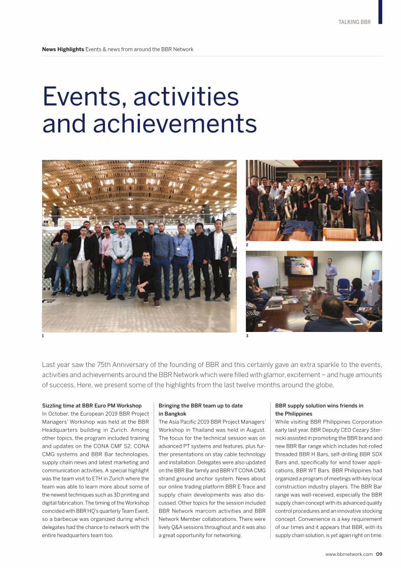
1 Delegates attending the 2019 European BBR
Project Managers’ Workshop, held at BBR HQ
in Zurich, had a special visit to ETH in Zurich
where they learnt more about the newest
construction techniques, such as 3D printing
and digital fabrication.
2 Some 25 BBR engineers from the region
attended the 2019 Asia Pacific BBR Project
Managers’ Workshop in Thailand. There were
lively Q&A sessions throughout and, of
course, it was a great opportunity for
networking too.
3 In Manila, BBR Deputy CEO Cezary Sternicki
assisted BBR Philippines in promoting the
BBR brand and new BBR Bar range to key
construction industry players within the
local market.
4 During the opening of IABSE’s 2019 Congress
in New York City, the President of IABSE,
Fernando Branco (far right), presented the
2019 IABSE Outstanding Structure Award
for the Mersey Gateway Bridge project to
representatives from COWI, Fhecor and
FCC Construcción.
5 This new accolade for the massive Kaikoura
Recovery project in New Zealand follows on
from two earlier international awards.
6 BBR Contech has been recognized with an
industry award for their work at Auckland’s
Wynyard Wharf. Pictured here (left to right)
are Adrien Marteddu, Mark Kurtovich and
Mole Powles.
7 Egyptian BBR Network Member ESPT made
a great impression at the Big 5 Construction
Conference in Cairo.
8 Stig Solbjør shows off a copy of the BBR
75th Anniversary edition of CONNÆCT at the
Spennteknikk booth during the annual
conference for Norway’s Department of
Transport (Statens vegvesen).
9 On the BBR Contech stand at the SESOC 2019
Conference in New Zealand are (left to right)
Adam O'Dea of SRG Global, with BBR
Contech’s Marc Stewart and Derek Bilby.
10 Kappa took a highly technical approach to
their appearance at the Road2Tunnel
Conference in Ankara, Turkey.
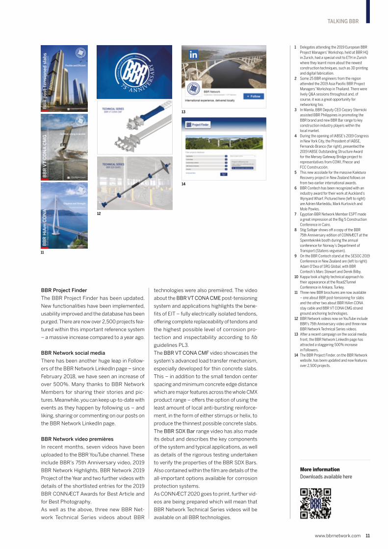
11 Three new BBR brochures are now available
– one about BBR post-tensioning for slabs
and the other two about BBR HiAm CONA
stay cable and BBR VT CONA CMG strand
ground anchoring technologies.
12 BBR Network videos now on YouTube include
BBR’s 75th Anniversary video and three new
BBR Network Technical Series videos.
13 After a recent campaign on the social media
front, the BBR Network LinkedIn page has
attracted a staggering 500% increase
in Followers.
14 The BBR Project Finder, on the BBR Network
website, has been updated and now features
over 2,500 projects.
Certified, strong & durable
BB
R V
T C
ON
A C
MG
Str
an
d g
rou
nd
an
ch
ors
fo
r g
eo
tec
hn
ica
l &
un
de
rgro
un
d e
ng
ine
eri
ng
ap
pli
ca
tio
ns
11
12
13
14
More informationDownloads available here

12 CONNÆCT | Edition 14
For a further cultural experience, delegates headed due south from
Zurich to the Titlis glacier. After a journey in a revolving panoramic
cable car to the top of the mountain 3,041m above sea level, their
courage was further tested by a walk across Europe’s highest
suspension bridge which is 100m long, yet only one meter wide.
Next, they walked through the glacier cave, with its eerie natural
lighting, where the ice is up to 5,000 years old and the temperature
is a constant -1.5°C.
It was most appropriate that, in BBR’s 75th Anniversary year,
delegates from around the world came together for the 2019
Global Annual BBR Conference in BBR’s homeland – Switzerland.
Zurich, Switzerland
Global BBR Conference 2019 goes to
After welcoming all delegates to
Zurich, BBR VT International’s CEO
Juan Maier, Cezary Sternicki and
Daniel Cuerdo presented the latest
news from BBR HQ. Next, Behzad
Manshadi gave details of recent
supply chain happenings, while
Xiaomeng Wang and Haifeng Fan
made presentations on BBR
geotechnical and post-tensioning
technology. There were also special
introductory presentations by Murat
Kutay of Kappa and Mohamed
Ashour of ESPT whose companies
had recently joined the BBR Network.
On the second day, special guest
Benjamin Dillenburger from ETH
Zurich gave a presentation entitled
‘Digitalization in Construction: A look
to the future’ which was followed by a
networking and discussion session.
One of the most important components of the
Annual Global BBR Conference is the opportunity
for networking which, alongside business
breakout sessions, is promoted by a variety of
social or cultural activities. This year, the welcome
event was a cruise on Lake Zurich in the company
of a pirate crew which led to some great
teamwork in solving knotty problems, but
resulted in at least one BBR Network delegate
getting all tied up!

www.bbrnetwork.com 13
TALKING BBR
BBR PROJECT OF THE YEAR 2019
Fernando Reig Bridge, Spain – innovative and technically challenging replacement of 38 stay cables by BBR PTE (FCC)
BBR CONNÆCT BEST ARTICLE AWARD
Winner: BBR Construction Systems
(Malaysia)
Title: Building a bridge to a new future
(KVMRT2)
Runner up: BBR Construction
Systems (Singapore)
Title: Innovative construction
combination (Wisteria Condominium
& Mall)
Highly commended: ETIC (France)
Title: Widening the motorway
(A9 viaduct strengthening)
BBR CONNÆCT BEST PHOTOGRAPHY AWARD
Joint Winner: BBR Contech
(New Zealand)
Title: ICE People's Choice Award 2018
(News item)
Joint Winner: ETIC (France)
Title: Signature stay cables (Saint
Jacques Bridge, Montréal, Canada)
Highly commended: BBR Adria
(Croatia)
Title: Time, materials & cost savings
(Max Stoja Shopping Center)
2019 BBR Award Winners
More aboutBBR Project of the Year
The 2019 BBR Network Project of the Year Award went to the Fernando Reig
Bridge where Spanish BBR Network Member,
BBR PTE (FCC), replaced all 38 stay cables.
After being presented with the award, a
delighted Juan Linero (right) held the
shining trophy up for all to admire.
The BBR CONNÆCT 2019 Best Article Award was presented by BBR VT
International’s Deputy CEO Cezary
Sternicki (left) to Yok-Lin Voon of BBR
Construction Systems Malaysia for his
company’s feature article about the
KVMRT2 metro rail project.
Pictured here is Daniel Cuerdo (left),
Business Development Manager, presenting
Mathias Kaminski from French BBR Network
Member ETIC with the BBR CONNÆCT 2019 Best Photography Award. This year,
top honors in this category were shared with
New Zealand-based BBR Contech.
Bruno Valsangiacomo, Executive Chairman of the Tectus
Group and BBR VT International’s founding shareholder,
addressed the delegates and guests at the BBR Gala Dinner.
He talked about the original vision of the three BBR founders
75 years ago – and how delighted they would have been to
know that it was still growing and being adapted to meet
future needs globally by the BBR Network.
BBR VT International CEO, Juan Maier, presented a check to Manuela Stier
of the Association for Children with Rare Diseases. With the generosity of
BBR Network Members and suppliers, this substantial donation will be
put to good use helping some 350,000 children and adolescents in
Switzerland who are affected by a rare disease. The Association provides
direct financial help, creates free family events to connect affected families
and works to raise the profile of the subject of rare diseases publicly.
Thanks to everyone for their generosity which has enabled us to support
this locally-based registered charity to continue its vital work.
At the BBR Gala Dinner, Svein Finstad from
BBR shareholder KB Spennteknikk managed –
with a little help from his partner Iris Liriano
– to cut the massive BBR 75th Anniversary
cake. He presented the first slice to Claudia
Valsangiacomo, wife of Bruno Valsangiacomo
and daughter of Antonio Brandestini, one of
the three BBR founders.

14 CONNÆCT | Edition 14
TALKING BBR
What does success look like? The answer to
this question can be hugely empowering. It
creates a vision not only of the goal a person
is aiming at, but also of that individual’s role in
achieving that objective. Take this to the next
level and consider what can be achieved when
a team of people share the same vision, then,
as we discovered in New Zealand, they can
quite literally move mountains.
Three centered approach
The NZ Transport Agency is focused on creat-
ing a transport system that is safer, provides
stronger community connections, supports
better access to economic and employment
opportunities – and that is resilient to with-
stand extreme weather events. Transport
is such a critical part of daily life for all New
Zealanders. We use transport for access to ser-
vices, freight, travel to work, education, health
and for visiting family and friends. Transport
networks allow businesses, regions and urban
areas to be well-connected and productive. To
ensure that everyone benefits from changes
happening in transport, we have adopted a
three strand approach which involves a sys-
tem response, people-centric response and
community response. All of these are targeted
on delivering real value for New Zealand – and
keeping our customer promise of facilitating
great journeys to keep New Zealand moving.
Our strategy was challenged to the maximum
in the aftermath of the November 2016 earth-
quake which severed vital access routes in
the Kaikoura region of New Zealand’s South
Island. Even before construction could begin,
mountains actually did need to be moved
and fractured hillsides made safe. At least 40
landslides blocked the 63km coastal transport
network between Clarence and Oaro.
Unifying vision
The North Canterbury Transport Infrastructure
Recovery (NCTIR) alliance was established to
restore the transport networks, and keep traffic
moving on alternate routes. This partnership
between the NZ Transport Agency and KiwiRail
was new territory, as was the collaboration
with construction firms and professional ser-
vice organizations on such a large scale. The
mandate of the NCTIR alliance was made clear
in its vision ‘Moving mountains to reconnect
communities’. This was a great unifying vision
which helped everyone understand why we
were there and who we were doing it all for.
Having this strong vision of reconnecting com-
munities helped to motivate a massive team
to achieve outstanding results. The work that
went into getting the rail, harbor and road open,
in just 13 months, is a testament to the profes-
sionalism, tenacity and sheer determination of
the workers involved, who wanted to make this
happen for a community that had suffered as
a result of the earthquake. By December 2017,
1,700 people had worked more than two million
hours to move mountains and reconnect the
communities isolated by the earthquake.
Driving success – understanding ‘the why’
It’s not all about asphalt, concrete and steel –
people are at the heart of achievements. The
key that drives success is to ensure that you
create an environment within which people
want to do their best and can do their best.
It is about making sure that everyone on your
project – from the project board to the labor-
ers – understands why they are doing what
they are doing (‘the why’) and understands
the important role they themselves play in
achieving this.
When our then new CEO asked a laborer on the
back of a traffic management truck what he did,
the laborer replied “I keep customers moving”. It
was clear that we had created an environment
that motivated the team. Rather than saying
that his job was putting cones out on the road,
he understood his ‘why’ – why he came to work
every day – to ensure customers were able to
travel through a work site safely and efficiently.
Looking ahead
The next challenge is about how to become
an agile organization to meet the changing
demands being thrown at us. The world is
changing at such a fast rate at the moment,
not only as a result of technical advancements,
but also of people’s expectations of instant
communications and real-time information.
It’s about engaging with people and sharing
visions of the future. On the construction site, we
find that making a connection with the workers
about ‘the why’ leads ultimately to an improved
culture, bringing with it health and safety, qual-
ity and productivity benefits. Whether you are
a client, consultant or contractor, it’s about
having early conversations – about the value
which is expected to be achieved by the project.
Taking time to talk about ‘the why’ will certainly
set everyone up for success and provide the
best possible solutions for the community as
a whole for generations to come.
Perspective Delivery of stakeholder value through shared understandings
Creating visions of success
For this edition of CONNÆCT, we are delighted to welcome as our guest Steve Mutton, Director Regional Relationships
(Upper North Island) for the New Zealand Transport Agency (NZTA). Steve is a project board member for large
alliance projects underway in New Zealand and has a reputation not only for getting the job done, but also for effective
management of stakeholder relationships. He presents us with some thoughts about the importance of shared visions.

In the last edition of CONNÆCT, we were
pleased to report that this landmark bridge
had attracted two awards – Outright Winner of
the 2018 Concrete Society Awards and also the
Infrastructure Award from the Royal Institution
of Chartered Surveyors (RICS). Now, the struc-
ture has been presented with the Outstanding
Structure Award by the International Associ-
ation for Bridge and Structural Engineering
(IABSE) who commented: “The Mersey
Gateway Bridge is an elegantly integrated
bridge, the first long span cable-supported
concrete bridge constructed in the UK which
marks a significant advancement in the use of
concrete for similar applications in the future.”
The bridge is the dramatic centerpiece of a
major highway scheme which was designed
as a catalyst for regeneration and to attract
investment into the region. This is the UK’s
only long-span cable-supported bridge to be
constructed primarily using cast in-situ con-
crete – post-tensioned with BBR VT CONA CMI
and BBR VT CONA CME internal and external
systems. Not only was the Mersey Gateway
Bridge opened ahead of program after three-
and-a-half years’ construction work, but the
whole scheme was also delivered in within bud-
get. This was a great achievement considering
that it was the largest infrastructure project
underway in England, outside of London.
www.bbrnetwork.com 15
BRIDGES
Mersey Gateway Bridge, Cheshire, England UK’s first long span cable-supported concrete bridge
Sparkling awards for bridge
The spectacular cascade of fireworks which heralded the official opening of the UK’s new Mersey Gateway Bridge
in October 2017 may seem, in hindsight, to have also anticipated the many accolades that this new structure would
attract. In recent months, this stunning bridge project across the Mersey estuary in North West England has been
presented with a third major industry award. Juan Linero of BBR PTE (FCC) reviews the project and the BBR Network’s
work on this important scheme.
1

16 CONNÆCT | Edition 14
BRIDGES
Structural overview
The bridge is 2,248m long in total, with a cen-
tral cable-stayed section of around a kilometer
in length, plus two access viaducts. The cen-
tral section has four bays supported by three
pylons founded in the Mersey estuary. Each
of the pylons is a different height, adding to
the uniqueness of the structure’s form. The
central pylon is 80m high, while the other two
pylons are higher – 110m on the north side
and 125m on the south. The pylons connect
with the bridge deck via 146 stay cables, with
a combined total length of 1,296km.
The new road network includes a total of 12
bridges and seven new or upgraded junctions
along a 9.2km route through the towns of
Runcorn and Widnes. In all, 127,425m3 of con-
crete was used for the scheme. The highest
environmental standards have been applied
to the project and, with bridge design focused
on minimal environmental impact, almost 1.5
million tons of material was recovered from the
site and reused in construction.
The construction joint venture was made up of
Kier Infrastructure and Overseas Limited (UK),
Samsung C&T Corporation (South Korea)
and FCC Construcción S.A (Spain). Its equity
partners were UK-based BBGI, FCC Construc-
ción from Spain and Macquarie Capital Group
Limited from Australia.
Specialist services
Specialist companies BBR PTE (FCC), Struc-
tural Systems (UK) Ltd and VSL Systems (UK)
Ltd formed a joint venture known as ‘BSV
Mersey JV’ in order to deliver the most highly
skilled and optimized specialist services within
our field to the Mersey Gateway project.
The post-tensioning for the 17-span approach
viaducts – with spans up to 65m long – was
executed by an experienced multicultural
team. A two stage process was adopted using
both the BBR VT CONA CMI internal and CONA
CME external systems. Firstly, longitudinal ten-
dons were installed from a Movable Scaffold
System (MSS) and secondly, the transversal
tendons were installed from a wing traveler.
For the main bridge, temporary vertical ten-
dons were used to reinforce and give stability
to the hammerheads during pylon construc-
tion – these were later de-stressed. We also
installed permanent transversal tendons
during the form traveler stage and external
tendons to reinforce and give continuity to the
main bridge and approach viaducts after the
deck sections had been joined.
The Mersey Gateway Bridge is an elegantly integrated bridge, the first long span cable-supported concrete bridge constructed in the UK which marks a significant advancement in the use of concrete for similar applications in the future.
2
3

www.bbrnetwork.com 17
BRIDGES
Construction milestones
June 2017 was a month of milestones for the
project. We celebrated completion of both the
final concrete pour and, less than two weeks
later, the first joining of the bridge with an
approach viaduct.
The new bridge deck was built in three sepa-
rate sections, working outwards from each of
the three pylons at a rate of around six meters
each week. The north and south main bridge
deck sections then had to be connected to the
approach roads – which are, in essence, via-
ducts built over a saltmarsh and canals.
The final concrete pour also signaled the depar-
ture of ‘Webster’, the 1,700t Movable Scaffold
System (MSS) which had been working on the
South Approach Viaduct for some ten months.
The final pour took place over a 28-hour period
and saw over 1,133m3 of concrete being poured
into formwork to complete the deck.
Meanwhile a few days later on the other side
of the River Mersey, the construction team
created a further project milestone. They con-
nected two sections of deck to link the North
Approach Viaduct to the north pylon deck span
– the first of four joins to take place during the
summer months.
The decks were closed with four steel restraint
struts and a concrete pour. After the concrete
had cured – around 18 hours later – the decks
were further locked together with external
post-tensioning tendons.
Engineered advantages
The Mersey Gateway Bridge is already ful-
filling its creators’ vision. The most recently
released figures show that between October
and December 2018, six million journeys were
made across the bridge – saving around 20
minutes on previous journey times. Also, the
hoped-for inward investment and job cre-
ation in the area is also beginning to be seen.
For the BBR Network, this has been a proj-
ect which has brought together some of the
leading players on the construction scene and
where some great teamwork and collaboration
developed to deliver not just a fine piece of
infrastructure, but also some real economic
and social advantages.
TEAM & TECHNOLOGY
DBFO – Merseylink Limited
Main contractor – Merseylink Civil Contractors Joint Venture: Kier Infrastructure and Overseas Limited, Samsung C&T ECUK Limited and FCC Construcción S.A.
Structural designers – Merseylink Design Joint Venture: COWI, Flint & Neill, Aecom, Eptisa and Fhecor
Technology – BBR VT CONA CMI internal, BBR VT CONA CME external
BBR Network Member – Structural Systems (UK) Limited & BBR PTE (FCC) (Spain)
1 A cascade of fireworks heralded the opening
of the Mersey Gateway Bridge. Image courtesy
of The Mersey Gateway.
2 The 1,000m long central cable-stayed section
of the Mersey Gateway Bridge.
3 Stressing operations underway on the lateral
post-tensioning tendons in the bridge decks.
Image courtesy of The Mersey Gateway.
4 View inside the deck of the main bridge,
showing the ducts (top and bottom)
containing the longitudinal BBR VT CONA CME
tendons. At the apex of the steel frames, the
lower stay cable anchorages can also be seen.
5 Stressing of BBR VT CONA CMI tendons for
one of the approach viaduct segments.
4
5

18 CONNÆCT | Edition 14
BRIDGES
KVMRT2, Kuala Lumpur, Malaysia Technology & techniques for long span crossing
Technical expertise overcomes challenges
Long Span Crossing 4 is one of the precast balanced cantilever bridges on the KVMRT2 SSP Line which is under
construction across the heart of the busiest town in Malaysia – Kuala Lumpur. With the various technical issues
anticipated along the way, BBR Construction Systems (M) has proven itself to be a great choice as launching
contractor and PT specialist for this part of the project. Zuhair Rawi, BBR Construction Systems’ Senior Design
Engineer for the project now takes us on a journey to explore the inside story of the challenges that have been
overcome during the construction of this special bridge type.
In the last edition of CONNÆCT, we described
how BBR Construction Systems had been
selected to work on package V202 of the
KVMRT2 SSP Line as post-tensioning and
launching specialist. We have been working
with the team to produce three different struc-
tures for the new metro viaduct – standard
spans, T-shaped piers and long span crossings.
Now, in this edition, we would like to share
further details of our work on Long Span
Crossing 4. The longest span of this cross-
ing is more than 45m from pier-to-pier and
cannot be accessed by the launching gantry
due to obstructions – either caused by live
traffic or landscape features. To overcome
the obstruction issues, this type of struc-
ture is typically constructed by the balanced
cantilever method.
Tight spaces
Long Span Crossing 4 is a four-span bridge
with a slender segment profile and a constant
segment height of 2.45m along the four spans.
The span length configuration of this bridge is
36m-46m-46m-36m and in total there are 15
segments for each cantilever span.
We opted for a direct launching method involv-
ing the use of a mobile crane for erecting each
segment. Behind this decision, there had
been a lot of brainstorming between the client
and ourselves about the best method for con-
structing the crossing. The major challenge
here was that one of the bridge spans needed
to sit directly under an existing bridge which
only allowed us a clear working height of 5.2m.
Initially, there had been another option – that of
using a segment erector. The 5.2m gap would
not have presented any problem for fitting
the segment erector and the restricted clear-
ance would have been fine for the launching
operation. However, the idea was shelved
because of installation issues. It would have
been difficult to install a segment erector –
and a lot more complex in terms of works
co-ordination. In this respect, other options
involving installation on top of a segment were
also discounted.
With that in mind, we then focused on the
direct launching method involving the use of
a mobile crane with a special set-up for the
lifting frame to fit into this restricted 5.2m
gap. The whole brainstorming process took
almost a year – discussions started at the
end of 2017 and physical segment launching
works only began in November 2018. This
sort of back-and-forth discussion happened
within BBR internally, with the client and
also with the crane supplier to ensure that
everything had been considered as regards
suitability and compatibility for each stage of
the lifting process.
Configuring the lifting frame
The main objective in designing a lifting frame
is to stabilize and properly distribute the
weight of the segment during the lifting pro-
cess. In this way, the segment could be lifted in
a safe and stable position and the lifting frame
would ease the lifting process especially during
segment placing and jointing.
At the same time, there was the issue of
the restricted headroom – or clearance gap
– under the existing bridge. Therefore, the
lifting pin on the lifting frame could only be
placed in a very low position – positioning was
limited to a maximum gap of 500mm between
the pin and top surface of the segment. This
gap was designed to allow for the thickness
of the crane hook. Several visits were made
to the crane supplier’s yard to test the com-
patibility and the requirements of the crane
supplier to ensure that the entire process
was sound.
The other factor considered was the spacing of
the lifting points. The positions of lifting points
were determined by the center of gravity of
the segment. Since every segment for other
bridges has different dimensions and profiles,
the lifting point spacings for each type of seg-
ment are different.
To fabricate a special frame which was only
suitable for one bridge would have been a
costly idea. So, the team arrived at the idea of
having a non-fixed lifting point that could fit
with any type of segment. After combining all
of the factors being considered, we designed a
steel frame with a combination of I-beams and
channels. It is a simple frame but it certainly
serves its purpose perfectly. Before the frame
was actually used, trial lifting tests were con-
ducted to further check whether any further
modifications were required.

www.bbrnetwork.com 19
BRIDGES
The testing
Immediately after the frame was fabricated,
it was taken, together with a segment, to
the crane supplier’s yard where tests were
carried out.
There were several objectives to the testing.
Firstly, we needed to ensure that the frame was
safe to be used for segment lifting in terms of
its capacity. Secondly, we wanted to make sure
that all links were well connected – especially
the pin which was to be hooked directly onto
the crane. Lastly, we needed to measure the
exact minimum working height that we could
achieve to satisfy the site requirements – here,
the goal was that the gap between the top
surface of the segment and the tip of the crane
should be less than 5.2m.
The first thing that we noticed during early
stage testing was that the frame was not
self-stable. This was because of a very low lifting
point which was below its own center of gravity.
However, after the frame was connected to
the top of the segment by prestressed bars
– and each of the bars had been stressed to
the required jacking force – the segment was
then lifted in a stable position. This happened
because, once the frame and segment were
properly connected by the prestressed bars,
they became a single monolithic element and
brought the center of gravity down to below
the lifting point – meaning that the segment
could remain stable during lifting.
After everything was set up, the segment was
then lifted to the desired height. The working
height was measured and the crane was set
to ensure that the minimum height of 5.2m
was achievable. This trial-and-error effort
of crane positioning and setting was finally
brought to a positive conclusion and the
lifting plan for the actual segment lifting was
drafted accordingly.
On site, all of the segments were safely
launched and placed without any issue. The
success of the project is primarily due to the
huge efforts and great co-ordination applied
by the team throughout the process.
1 Segment placing and jointing was supported
on temporary steel props.
TEAM & TECHNOLOGY
Owner/developer – MRT Corporation Sdn Bhd
Main contractor – Ahmad Zaki Sdn Bhd (AZSB)
Technology – BBR VT CONA CMI internal, BBR VT CONA CME external, Balanced cantilever
BBR Network Member – BBR Construction Systems (M) Sdn Bhd (Malaysia)
1

20 CONNÆCT | Edition 14
BRIDGES
Moracica Bridge, Republic of Montenegro Cantilever bridge construction across valleys
Span closure for record-breaking bridge
The deck of the mighty Moracica Bridge in Montenegro, the tallest bridge in the
former Yugoslavia region, has been completed with the help of BBR VT CONA
CMI internal and CONA CME external post-tensioning. Tomislav Lozancic of
BBR Adria provides a brief overview of the project and an update on progress
during the past year.
1

www.bbrnetwork.com 21
BRIDGES
1&2 The balanced cantilever construction
of the 180m high Moracica Bridge in
Montenegro has been completed.
The project features both BBR VT CONA
CME and CONA CMI post-tensioning.
TEAM & TECHNOLOGY
Owner/developer – Government of Montenegro, Ministry of Transport and Maritime Affairs
Architect – Mladen Ulicevic, Željko Licina
Main contractor – China Road & Bridge Corporation d.o.o.
Technology – BBR VT CONA CMI internal, BBR VT CONA CME external
BBR Network Member – BBR Adria d.o.o. (Croatia)
The joining of all the spans of the massive
Moracica Bridge was celebrated in October
2019 by a visit from Duško Markovic the Prime
Minister of Montenegro. He expressed his
satisfaction with the progress and described
it as a “special day for Montenegro”, while
thanking all those involved in the project.
Moracica Bridge is the largest structure on the
priority section of the Bar-Boljare motorway
and is believed to be the third largest bridge
in Europe. Stretching elegantly across the
Moraca River valley and plateau below, the
960m long bridge has six spans. The bridge
deck is supported on five piers, the tallest of
which is 180m.
Climbing formwork was used to construct
the bridge piers and the bridge deck was
constructed by the balanced cantilever
method. The balanced cantilever sections
feature BBR VT CONA CMI internal post-
tensioning, while CONA CME external
post-tensioning was installed following deck
segment completion.
The bridge will be fully completed in early 2020,
in time for the opening of this first section of
the motorway in the summer. When the whole
170km long scheme, known as pan-European
Corridor XI, is complete it will offer a ferry
and motorway link between Bari in Italy and
Bucharest, Romania.
2

22 CONNÆCT | Edition 14
BRIDGES
Windsor Bridge, NSW, Australia Post-tensioning & incremental launching
Talent for increasing productivity
Thirty years on from their first launched bridges in the 1980s, Australian
BBR Network Member SRG Global are still delivering sound specialist bridge
construction services to their clients. Sean Kelly, Civil Manager in Eastern
Australia provides this report on the successful completion of post-tensioning
and incremental launching for a 157m five span, twin concrete girder bridge
over the Hawkesbury River in Windsor, 50km north-west of Sydney.
1

www.bbrnetwork.com 23
BRIDGES
Windsor is the third-oldest place of British
settlement on the Australian continent, with
settlement at the location first established in
approximately 1791. At over 140 years old, the
existing Windsor Bridge – built for horse-drawn
vehicles and foot traffic – has recently been
replaced to ensure a safer journey for vehi-
cles and pedestrians, with the former reaching
19,000 daily.
Incremental launching girder
We modified our existing launch girders which
had previously been used to deliver the incre-
mentally launched Mandurah and Seaford
Bridges. Due to the shallower deck profile
needed for the 31m continuous spans, the
launch girder consisted of only the front three
of the four sections used for Mandurah Bridge.
To ensure the design loadings were appropri-
ately managed, significant modifications were
made at the girder connection. A completely
new girder connection section was full pen-
etration-welded to the existing 32mm web,
both vertically and horizontally.
Each launch girder was stressed onto the
first segment by ten 50mm diameter high
tensile stress bars, each stressed to a load of
1,375kN at lock off (68% of MBL). In addition to
ensuring the pivotal connection of the
stiff launch girder to the first segment, the
bottom row of girder connection bars was then
used to fix the bridge longitudinally to facilitate
the permanent bearing installation process
after launching.
Launch bearings
The designers made a conscious effort to detail
the permanent works in a manner which com-
plemented the temporary works requirements.
An example of this was the adoption of perma-
nent bearings, which were capable of being
used as temporary bearings during launching.
The decision to use large reinforced elastomeric
bearings, with top and bottom steel plates,
saved time and cost post-launch by simpli-
fying the transition to permanent bearings.
PTFE sliding pads were still adopted to ensure
the launching forces were managed appro-
priately and these were located between the
bridge soffit and stainless steel upper plate of
the elastomeric bearing.
To guide the bridge transversely during the
launch, reinforced concrete nibs were built into
the pier heads that allowed guidance via the
inner webs. In addition, conventional side guide
rollers were adopted at the abutments and in
the casting yard.
2
3

24 CONNÆCT | Edition 14
BRIDGES
4
Launching equipment
The bridge was launched on a 1.296% uphill
gradient, making the lift-and-shift launching
solution viable over other techniques such as
strand pulling systems. A brake saddle was
incorporated into the launching equipment
thrust block for simplicity, with the tail end of
the bridge transferring over to a temporary
hydraulic jack brake saddle during the final
meters of the last launch.
The bridge weight and gradient meant the hori-
zontal shifting force would not be the governing
factor when selecting the appropriate launch-
ing equipment. The support locations dictated
that the vertical lift requirements would drive
the decision in the selection of launching
equipment. The critical lift was during segment
three, which resulted in the choice of a sys-
tem that furnished each girder with launching
equipment capable of a 785t lift and 3,040kN
shift. The incremental launching of a segment
was able to reach a rate of approximately 4.7m
per hour – meaning that on occasions segment
launches took the team less than four hours.
Post-tensioning
The twin concrete girder bridge is made
up of two 2m wide by 1.85m deep beams,
monolithically stitched together by a nomi-
nally 350mm thick deck which is 14.9m wide.
The bridge is typically constructed using 34
concentric post-tensioned tendons, with
sizes varying between five and 19 strands. The
staggered concentric tendons are coupled
together with the BBR VT CONA CMI Type K
couplers at every second segment.
At the completion of launching and for the final
loading conditions, a total of six – three per
girder – 25-strand continuity tendons were
pushed, stressed and grouted. The tendons
run the full 157m of the bridge and are stressed
at both ends to manage the friction losses.
For the final three segments of the bridge,
the deck widens up to 19.5m to make
provision for the road and pedestrian
approaches. As a result, there was a require-
ment to install a total of 52 five-strand
transverse flat slab tendons to manage the
additional cantilever loading.
The staggered concentric tendons are coupled together with BBR VT CONA CMI Type K couplers at every second segment.

www.bbrnetwork.com 25
BRIDGES
1 Overview during segment three construction
of the new Windsor Bridge which replaces the
adjacent upstream bridge.
2 With nine of the 10 segments constructed,
the launch girder closes in on Abutment A.
3 Permanent bearings were used as temporary
bearings during launching – saving time and
costs. Here, beneath the launching girder, the
reinforced elastomeric bearings with top and
bottom steel plates can be seen.
4 Stressing of the BBR VT CONA CMI tendons
underway.
5 (Top) Launch girder nose jacks approaching
the Abutment A bearings for the final launch.
(Middle) Launch girder nose jacks retracted,
ready to be extended to take up the deflection
over the 30m span.
(Bottom) Launch girder nose jacks extended
to take up the deflection over the 30m span.
TEAM & TECHNOLOGY
Client – Roads and Maritime Services
Main contractor – Georgiou Group
Consulting engineer – Jacobs Engineering Group
Technology – BBR VT CONA CMI internal, Incremental launching
BBR Network Member – SRG Global (Australia)
5
Cycle time
Various efficiencies were gained as a result of
both the permanent works design and tem-
porary works measures. These enabled the
working day cycle time to be as low as six days
between launches.
Firstly, we adopted a single pour per segment
approach. Due to the closed girder and slab
arrangement, each 15.7m segment could be
executed in just a single pour, which ensured
optimum cycle time. Launch bridges are more
typically designed as box girders, that often
require the segment pours to be split in two.
Another efficiency was achieved through our
instigation of adopting stressing gantries,
which enabled cranes to be freed up for other
activities during stressing. The design meant
that on average 16 to 18 multistrand tendons
required stressing before the launch. The
gantries were located over each girder to allow
simultaneous stressing of girders. The gan-
tries allowed the jacks to travel transversely,
longitudinally and vertically which enabled
segments to be stressed in only two to three
hours. Front pulling multistrand hydraulic jacks
were also adopted for their speed and simplicity
of installation.
This was an excellent project from so many
angles – technically challenging, great team-
work within the wider professional team
and a first class result for our customer –
and, of course, the traveling public. Our whole
team is now looking forward to the next
opportunity to bring that extra value-add to
a project with our specialist knowledge and
techniques.

26 CONNÆCT | Edition 14
BRIDGES
Santa Monica-Lawton Bridge, Metro Manila, Philippines
Trio of BBR technologies speed bridge construction
River crossing with latest BBR technology
With the Philippine economy expanding at an average annual rate of around
six percent since 2010, vehicles have become more affordable to a greater
number of people. The Government is hard-pressed to keep up with the
creation of additional road infrastructure to meet the resultant surge in traffic
volumes. Rey Singh of BBR Philippines Corporation tells the story of how,
with the very latest BBR post-tensioning and bar technology, his company is
supporting the efficient creation of an important new highway bridge.
1
The capital city of the Philippines is Manila
and, together with another 15 cities and a
lone municipality, it comprises the Greater
Manila/Metropolitan Manila Area. With an esti-
mated daytime population of approximately
15 million people crammed into an area of
only 620km2 – equivalent to around 40m2
per person – congestion is definitely a prob-
lem. Metro Manila has been listed as the
fourth most populous urban area in the world
after Tokyo-Yokohama in Japan, Jakarta in
Indonesia and Delhi in India.
Manila is a city built on a bay and, conse-
quently, its major roads radiate outwards
from the center towards Circumferential
Roads. The most important artery in Metro
Manila’s road network is EDSA (Epifanio De
Los Santos Avenue) also known as Circum-
ferential Road 4 (C4) and it has already
been supplemented by Circumferential
Roads 5 and 6 (C5 and C6 Roads). Unfor-
tunately, the C6 Road is the last that could
be built as it runs right on the shores of the
massive freshwater Laguna Lake which
extends across much of the island of Luzon
at this point.
Metro Manila is divided by the Pasig River
which runs from the lake to Manila Bay. Thus,
to ease the pressure on the Circumferential
Roads, especially EDSA, bridges need to be
constructed across the Pasig River.
One such scheme commissioned by the Gov-
ernment, through its infrastructure arm, the
Department of Public Works and Highways
(DPWH), is the Bonifacio Global City (BGC)
to Ortigas Center Road Link Project.

www.bbrnetwork.com 27
BRIDGES

Project outline
The aim of the project is to connect the busi-
ness districts of BGC which lie south of the
Pasig River and Ortigas Center to the north.
New infrastructure includes a 408m viaduct
and 157m approach road on the southern side,
a 210m balanced cantilever bridge to cross
the Pasig River and a 69m viaduct and 160m
approach road on the northern section. The
new roadway will be just over a kilometer long.
The balanced cantilever bridge is the Santa
Monica-Lawton Bridge. It is named after the
streets which it will join – Santa Monica Street
on the northern riverbank and Lawton Avenue
on the south side.
Technical aspects
The original plans for the balanced cantile-
ver bridge called for two side spans of 60m
each and a center span of 90m. However,
this configuration would have placed the pier
substructures right in the middle of the river
and therefore taken up more valuable program
time to design and construct.
As there is some urgency to relieve traffic
congestion on the EDSA and C5 Roads, it
was proposed that the bridge center span be
increased to 105m and the side spans reduced
to 52.50m each. This is sufficient to cross the
approximately 100m-wide Pasig River and
locate the substructures on land.
The bridge has a four lane roadway with side-
walks and a total width of 19m. At its largest
cross-section at the pier substructures, it has
a box girder depth of six meters with a lower
slab thickness of one meter. Its smallest cross-
section is in the center span, where it has a
box girder depth of 2.80m with a lower slab
thickness of 300mm. The two barrel box
girders have webs with thicknesses of 500mm.
Each half of the bridge has 29 segments with
equal lengths of 3.10m.
28 CONNÆCT | Edition 14
BRIDGES
3
2
This is the first time that BBR VT CONA CMI internal, BBR VT CONA CMF S2 flat and BBR H Bar technologies are being used here in the Philippines.

www.bbrnetwork.com 29
BRIDGES
New BBR technologies
BBR Philippines Corporation helped the
main contractor to achieve optimum design
efficiency for the bridge superstructure. The
longitudinal post-tensioning tendons were
made to be uniform BBR VT CONA CMI internal
1906 tendons instead of the previously speci-
fied CONA CMI 3106 tendons. This allowed the
use of smaller stressing jacks and increased
production rates on site. The shortest longi-
tudinal tendon is 12.20m, while the longest is
102.10m. There are 60 upper tendons and 28
lower tendons in the center span, while in the
side spans there are 16 lower tendons.
Transverse post-tensioning was also intro-
duced using BBR VT CONA CMF flat 0406
tendons spaced at 900mm centers in the
top slab. All transverse tendons are 19m long.
The total post-tensioning tonnage for the
balanced cantilever bridge superstructure is
around 252t. Add to that approximately 761t of
reinforcing steel bars and 4,803m3 of ready-
mixed concrete and seasoned engineers will
have a fairly good idea of what the superstruc-
ture works involve.
Also, 348 threaded 40mm diameter BBR H930
Bars are being used for permanent stressing.
They are being installed in the webs of the
two barrel box girders. The BBR H Bars will
range from 2.826 to 5.861m long and the
total weight of bars required is almost 24t.
To speed up delivery and installation, the BBR
H930 Bars were pre-customized in the BBR
production facility – cut to length and bundled
in the required sequence – thus our work on
site was reduced and some time savings were
generated. An extra benefit for the project was
the BBR pre-delivery inspection (PDI) process
which is carried out for every BBR component
or system. This meant that potential mistakes
in the quantity or packing sequence were ruled
out and we were able to adhere to the tight
delivery and installation schedule.
As an added service to the main contractor,
our work also includes operation of their
form travelers.
This is the first time that BBR VT CONA CMI
internal, BBR VT CONA CMF S2 flat and BBR
H Bar technologies are being used here in
the Philippines. Even in the face of fierce
local competition, we were able to secure
this project based on our ability to provide
a competitive service and a single source
for major components. We now look forward
to the successful completion of the Santa
Monica-Lawton Bridge – and can reflect that,
with these new BBR technologies and our
specialist experience, the team from BBR
Philippines Corporation is helping the Govern-
ment to cross the Pasig River.
1 The 210m balanced cantilever bridge will
cross the Pasig River, joining Santa Monica
Street on the northern riverbank with Lawton
Avenue on the south.
2 Construction is underway for the new Santa
Monica-Lawton Bridge in Metro Manila,
Philippines, part of the Bonifacio Global City
to Ortigas Center Road Link Project which will
connect two of the city’s business districts.
3 The new bridge approaches the halfway point
across the Pasig River.
4 The bridge will have a total of 58 segments
with equal lengths of 3.10m.
TEAM & TECHNOLOGY
Owner – Department of Public Works and Highways, Republic of the Philippines (DPWH)
Main contractor – Persan Construction, Inc.
Technology – BBR VT CONA CMI internal, BBR VT CONA CMF flat, BBR H Bar
BBR Network Member – BBR Philippines Corporation
4

30 CONNÆCT | Edition 14
BRIDGES
Bratislava Bypass, Slovakia BBR post-tensioning for five bridges
Bridging the crossroads of Europe
By the time CONNÆCT 2020 is published,
the team from BBR Polska will have finished
their work on the southern part of the Bratislava
Bypass which will link the west and east of
Slovakia. Pawel Surman provides this account
of the work his company is undertaking on the
post-tensioning of five bridges along the route.
Bratislava, situated on both banks of the River
Danube, has the unique distinction of being
the only national capital which borders two
countries – Austria and Hungary – and its
central location is regarded as a crossroads
of Europe. With strong economic growth in the
2000s, the Bratislava region currently benefits
from not only increased inward investment, but
also the many government institutions which
are headquartered there. In this climate, the
construction industry is burgeoning too, with
many building projects underway.
1

www.bbrnetwork.com 31
BRIDGES
Transport network improvements
Improvements to the transportation network
have been undertaken – with some still under-
way – to support this commercial growth.
One such project is the Bratislava Bypass
which is part of the southern expressway
network. It is being constructed as a Pub-
lic Private Partnership (PPP), the 30-year
design-build-finance-operate (DBFO) conces-
sion for which was awarded to Zero Bypass
Ltd – a consortium involving Cintra, Macqua-
rie Capital and PORR AG – by the Slovakian
Ministry of Transport, Construction and
Regional Development.
In turn, Zero Bypass Ltd appointed D4R7
Construction s.r.o. – a consortium formed
between Ferrovial Agroman and PORR – as
the main contractor for the design and build
of the new highway.
New highway link
The new highway link which is expected to
carry some 45,000 vehicles each day will
increase transport capacity and improve
local connectivity. It is envisaged that
traffic between Austria, Hungary, the Czech
Republic and Poland, which currently travels
through urban areas, will be accommodated on
the bypass.
Work began on the project – estimated to
be valued at €1.46bn – in November 2016.
The scheme involves the construction of a
new 27km long section of the D4 motorway,
plus a 32km long expressway, the R7. The
dual two lane D4 motorway will serve as a
bypass to eastern Bratislava and the new R7
radial expressway will have up to three lanes
in each direction and run south-eastwards
from Bratislava.
PT installation
BBR Polska has been tasked with the supply,
installation and stressing of post-tensioning
systems for five bridges over the Bratislava
to Galanta railway line, as part of the Jarovce-
Ivanka-Sever section of the project. Our work
here will see the installation of a total of 276
BBR VT CONA CMI internal tendons for which
almost 225t of prestressing steel and over
10,000m of steel ducting will be used.
The BBR Polska team’s work is being carried
out over live railway lines, therefore there are
additional health and safety requirements. Our
experience from many similar projects around
railway infrastructure in Poland and from inter-
national contracts has enabled us to quickly
adapt to the locally applicable requirements.
As a multinational project, the interface with
very different environments and cultures,
codes and work standards was one of the major
challenges. The presence and the support of
resident technicians and engineers proved
to be a decisive leverage which promoted
speedier familiarization with the specific
requirements and has broadened our own
outlook, not only in terms of work experience
on an international basis, but also of cross-
cultural co-operation. This all gives BBR Polska
yet more important experience upon which
we will base the exploration of further inter-
national projects in the future.
1 BBR Polska is providing post-tensioning for five
bridges, all over railway lines, for the Bratislava
Bypass project in Slovakia. Photograph
courtesy of D4R7 Construction s.r.o.
2 The team from BBR Polska is installing a total
of 276 BBR VT CONA CMI internal
post-tensioning tendons for their contract for
five bridges.
3 Visualization of the Ivanca-Sever Interchange
on the Bratislava Bypass, along with new
bridges over railway lines. Image courtesy of
D4R7 Construction s.r.o.
TEAM & TECHNOLOGY
Client – Zero Bypass Ltd
Main contractor – D4R7 Construction s.r.o.
Technology – BBR VT CONA CMI internal
BBR Network Member – BBR Polska Sp. z.o.o.
2
3

32 CONNÆCT | Edition 14
BRIDGES
Highway & rail bridges, Norway Post-tensioning & incremental launching for bridges
Bridge quintet in Norway
Recent months have seen the award of five contracts for work on major road or
railway bridge schemes to Norwegian BBR Network Member KB Spennteknikk AS. CTO, Stig Solbjør offers some background to the projects and describes
how BBR technology and expertise is contributing to their realization.
Norway is famed for its spectacular fjords,
islands, lakes and mountains, but while we –
and many tourists too – enjoy these geological
features, this complex geography presents
challenges for those who need to travel around
the country.
Free cantilevered bridge
The huge project to improve the around
1,100km-long E39 Coastal Highway Route
between Kristiansand in the south of Norway
and Trondheim in the north will reduce travel
time by half. The time savings will be achieved
by replacing seven current ferry crossings
with tunnels or bridges, as well as upgrading
a number of existing stretches of road. Along
the route, there are eight fjords one of which
is the Trysfjord, where we will be supplying
post-tensioning services for a new 520m-long
free cantilevered bridge. The bridge has a main
span of 260m, making it one of the longest
concrete cantilever spans in the world.
Incremental launching
After we had won the above contract, the great
strength and extensive expertise of the BBR
Network was again proven – by the award
of a project for four incrementally launched
bridges, in the face of strong competition
from a large worldwide supplier offering
total service capabilities. We invited our cus-
tomer to visit BBR Polska in Warsaw and see
bridge launching operations in progress there.
The combination of our excellent local knowl-
edge, being a long-established locally based
business, plus our ability to offer of a package
including incremental launching, installation of
the launching nose and post-tensioning were
decisive in winning the contract.
Now, we look forward to our co-operation with
BBR Polska on the E39 Kristiansand Vest-
Mandal Øst project for the bridges at Monan
and Rossevann. The work at Rossevann is
particularly sensitive because the bridge will
stretch across a drinking water source which
must be protected. This is why the incremental
launching method is most suitable – there will
be no concrete casting over the water.
New stretch of E6
A further route under construction is a new
section of the E6 between Kolomoen and
Moelv which passes close to the city of Lille-
hammer, site of the 1994 Winter Olympic
Games. The E6 is a European route and the
main north-south road through Norway and
the west coast of Sweden, covering a total
of 3,000km.
E39 Coastal Highway Route: Visualization of the new Trysfjord Bridge which will feature one of the world’s longest free cantilever spans.
Image published with kind permission of Nye Veier, Norconsult & AF Gruppen.

www.bbrnetwork.com 33
BRIDGES
There are around 30 bridges on the route of
this new four lane highway, including some on
the highway itself as well as overpasses which
require post-tensioning. To meet the require-
ments, we are installing the BBR VT CONA CMI
BT system in three different sizes – 15, 19 and
22 strand systems, all using 15.7 mm diameter
prestressing strands.
Northern Islands bridges
At the same time, on the west coast of Nor-
way, near Ålesund, we are also working on the
construction of two post-tensioned concrete
bridges – Hamnaskjersund and Lauke Bridges
– as part of the FV.659 Nordøyvegen project.
The three span Lauke Bridge will be 110m long
and lies just south of the islands of Lauka and
Lisjelauka. It will have a 41m long main span and
two side spans of 34m long each. The overall
width of the bridge will be 12.1m. The 200m long
Hamnaskjersund Bridge will have seven spans,
ranging in length from 21m to 38m, and a total
width of 11.1m. We will be installing the BBR VT
CONA CMI BT 1906 system for both bridges.
BBR technology package right on track
Meanwhile, a mixed package of BBR technol-
ogy and services is being delivered for the
Venjar to Eidsvoll Nord Intercity Rail Project –
a major rail improvement scheme in the east
of Norway. The terrain is challenging and fea-
tures a hilly ravine landscape with loose rock
and demanding ground conditions. Around
a third of the route will travel on bridges or
in tunnels.
Over the two year period of our contract, we
will be providing post-tensioning for the four
bridges on the line, as well as bearings, PT
bars and special bearings. We will be using
BBR VT CONA CMI internal post-tensioning
of differing sizes, chosen to meet the vary-
ing requirements. We will also be supplying
and installing TOBE Bearings, plus a series of
special bearings for high horizontal loads.
Our ability to provide a range of technologies
and services for this project greatly enhanced
our position when tendering. We are finding
that customers prefer to have a single point
of responsibility for multiple services.
TEAM & TECHNOLOGY
E39 KRISTIANSAND VEST-MANDAL ØSTClient – Nye Veier AS
Main contractor – AF Gruppen
Specialist subcontractor – Kruse Smith Entreprenør
Consulting engineer – Norconsult
Technology – BBR VT CONA CMI internal, Pot bearings, Incremental launching
BBR Network Members – KB Spennteknikk AS (Norway) + BBR Polska Sp. z.o.o. (Poland)
E6 KOLOMOEN-MOELVClient – Nye Veier AS
Main contractors – Hæhre Entreprenør AS & Veidekke Entreprenør AS
Technology – BBR VT CONA CMI internal, Pot bearings
BBR Network Member – KB Spennteknikk AS (Norway)
FV659 NORDOYVEGENClient – Statens Vegvesen
Main contractors – Skanska Norge AS
Consulting engineer – Statens Vegvesen
Technology – BBR VT CONA CMI internal
BBR Network Member – KB Spennteknikk AS (Norway)
VENJAR-EIDSVOLL NORD INTERCITY RAIL PROJECTClient – Bane Nor
Main contractor – NCC Norge AS
Technology – BBR VT CONA CMI internal, Pot bearings
BBR Network Member – KB Spennteknikk AS (Norway)

34 CONNÆCT | Edition 14
BUILDINGS
High Rise Buildings Singapore
Shaping the Singapore skyline
In recent years, BBR Construction Systems (Singapore) has delivered technology and services for no less than
FOUR major skyscraper projects which are shaping the island nation’s skyline. In previous editions of CONNÆCT,
we have only been able to publish either artist’s impressions of the finished structures or photographs of work in
progress to illustrate technical articles about the construction of these challenging projects. Now, we are taking the
opportunity to revisit Singapore and, using recent photographs, show these amazing high rise structures in their
completed forms. All projects are Green Mark Platinum rated by the Buildings and Construction Authority (BCA) of
Singapore, highlighting their environmental and sustainability credentials – to which BBR post-tensioning, with its
materials, time and cost saving features, has contributed.
1
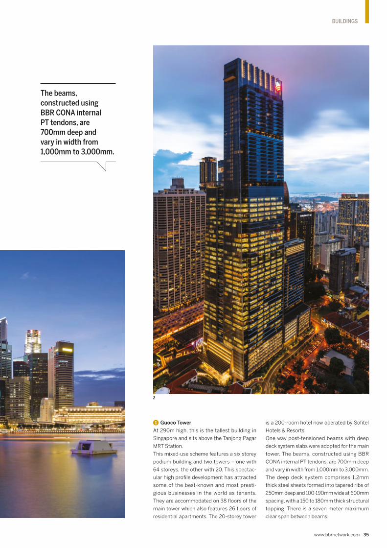
www.bbrnetwork.com 35
BUILDINGS
1 Guoco Tower
At 290m high, this is the tallest building in
Singapore and sits above the Tanjong Pagar
MRT Station.
This mixed-use scheme features a six storey
podium building and two towers – one with
64 storeys, the other with 20. This spectac-
ular high profile development has attracted
some of the best-known and most presti-
gious businesses in the world as tenants.
They are accommodated on 38 floors of the
main tower which also features 26 floors of
residential apartments. The 20-storey tower
is a 200-room hotel now operated by Sofitel
Hotels & Resorts.
One way post-tensioned beams with deep
deck system slabs were adopted for the main
tower. The beams, constructed using BBR
CONA internal PT tendons, are 700mm deep
and vary in width from 1,000mm to 3,000mm.
The deep deck system comprises 1.2mm
thick steel sheets formed into tapered ribs of
250mm deep and 100-190mm wide at 600mm
spacing, with a 150 to 180mm thick structural
topping. There is a seven meter maximum
clear span between beams.
2
The beams, constructed using BBR CONA internal PT tendons, are 700mm deep and vary in width from 1,000mm to 3,000mm.
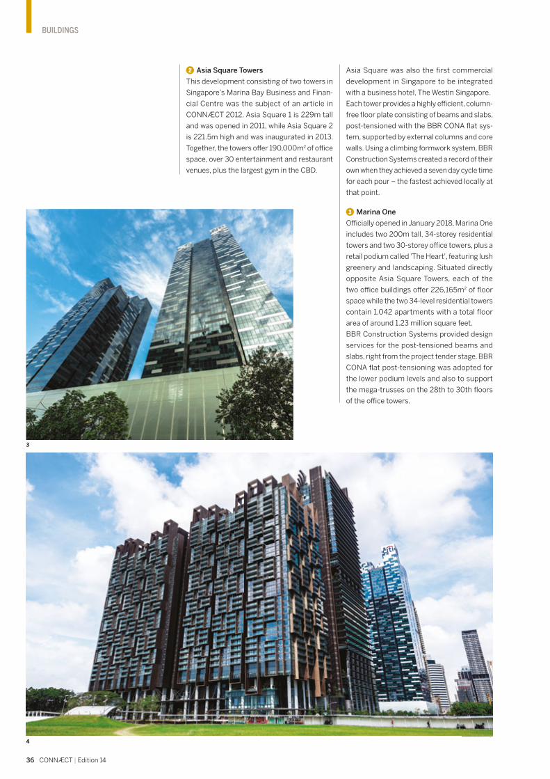
36 CONNÆCT | Edition 14
BUILDINGS
Asia Square was also the first commercial
development in Singapore to be integrated
with a business hotel, The Westin Singapore.
Each tower provides a highly efficient, column-
free floor plate consisting of beams and slabs,
post-tensioned with the BBR CONA flat sys-
tem, supported by external columns and core
walls. Using a climbing formwork system, BBR
Construction Systems created a record of their
own when they achieved a seven day cycle time
for each pour – the fastest achieved locally at
that point.
3 Marina One
Officially opened in January 2018, Marina One
includes two 200m tall, 34-storey residential
towers and two 30-storey office towers, plus a
retail podium called 'The Heart', featuring lush
greenery and landscaping. Situated directly
opposite Asia Square Towers, each of the
two office buildings offer 226,165m2 of floor
space while the two 34-level residential towers
contain 1,042 apartments with a total floor
area of around 1.23 million square feet.
BBR Construction Systems provided design
services for the post-tensioned beams and
slabs, right from the project tender stage. BBR
CONA flat post-tensioning was adopted for
the lower podium levels and also to support
the mega-trusses on the 28th to 30th floors
of the office towers.
2 Asia Square Towers
This development consisting of two towers in
Singapore’s Marina Bay Business and Finan-
cial Centre was the subject of an article in
CONNÆCT 2012. Asia Square 1 is 229m tall
and was opened in 2011, while Asia Square 2
is 221.5m high and was inaugurated in 2013.
Together, the towers offer 190,000m2 of office
space, over 30 entertainment and restaurant
venues, plus the largest gym in the CBD.
3
4

www.bbrnetwork.com 37
BUILDINGS
TEAM & TECHNOLOGY
1 GUOCO TOWERDeveloper – Guocoland Limited
Architect – Skidmore, Owings & Merrill LLP (SOM)
C&S consultant – Arup (Singapore) Pte. Ltd
Main contractor – Samsung C&T Corporation
Technology – BBR CONA internal
BBR Network Member – BBR Construction Systems Pte. Ltd. (Singapore)
2 ASIA SQUARE TOWERSOwner – MGPA
Main contractor – Hyundai Engineering & Construction
Structural consultant – Meinhardt (S) Pte Ltd
Technology – BBR CONA flat
BBR Network Member – BBR Construction Systems Pte. Ltd. (Singapore)
3 MARINA ONEOwner – M+S Pte Ltd
Main contractors – Hyundai Engineering & Construction and GS Engineering & Construction JV
Architect – Ingenhoven architects
Structural consultant & M&E engineer – Beca Carter Hollings & Ferner (SE Asia) Pte Ltd
Technology – BBR CONA flat
BBR Network Member – BBR Construction Systems Pte. Ltd. (Singapore)
4 SOUTH BEACHOwner – South Beach Consortium
Architect – Foster + Partners
Main contractor – Hyundai Engineering & Construction Co. Ltd
C&S consultant – Arup (Singapore) Pte Ltd
Technology – BBR CONA internal, BBR CONA flat
BBR Network Member – BBR Construction Systems Pte. Ltd. (Singapore)
The project involved a total gross floor area of
146,827m2 in two towers. The 35-storey North
Tower contains office space while, in the 45
storeys of the South Tower, hotel and residen-
tial accommodation was created. Walkways
and public spaces within the development are
sheltered from the tropical climate by a state-
of-the-art environmental canopy.
In general, the 265-375mm thick post-
tensioned floor slabs were constructed using
BBR CONA flat tendons, with post-tensioned
banded beams at the perimeter. The slabs for
the North Tower’s ‘Sky Garden’ were 600mm
thick and, for the hotel floor in the South Tower,
there was a reinforced concrete floor slab with
a post-tensioned banded beam and transfer
beam. The six storey podium also featured a
post-tensioned beam and slab scheme.
There were some interesting challenges
for the BBR Construction Systems team in
Singapore. For example, the inclination of some
of the columns meant that the vertical load
from upper floors created a ‘kick-out’ force
when columns changed direction of incline.
Thus, additional horizontal BBR CONA flat
tendons were installed at the 10th to 12th
storeys of the North Tower and 14th to 16th,
22nd and 32nd floors of the South Tower to
tie these inclined columns back to the ver-
tical core. Formwork also required special
considerations during design, as well as addi-
tional precautions and supervision during the
erection stage to ensure capacity and safety.
Part of the formwork was designed to be free-
standing – because, after the 11th storey, the
building edge extends outwards before inclin-
ing inwards again.
4 South Beach
Completed in 2016, the two towers of Sin-
gapore South Beach – both 218m tall – are
strategically located on Beach Road, bordering
the CBD. The two distinctively sloped towers
are part of a wider scheme which incorporates
four historic buildings already on the site.
1 The famous Singapore skyline features several
new skyscrapers, created in recent years with
BBR technology and services.
2 Guoco Tower – Singapore’s tallest building,
efficiently realized with BBR CONA flat
technology.
3 Asia Square Towers – construction of beams
and slabs post-tensioned with BBR CONA flat
tendons, supported by external columns and
core walls created a highly efficient,
column-free floor plate.
4 Marina One – BBR CONA flat post-tensioning
was adopted for the lower podium levels and
also to support the mega-trusses on the 28th
to 30th floors of the office towers.
5 South Beach – additional BBR CONA flat PT
tendons were installed to tie inclined columns
back to the vertical core.
The horizontal transfer tendons were planned for the sky garden levels where there was large headroom, allowing for structural slabs to be up to 600 millimeters thick without affecting the architectural intent.
Extract from Schnizer R, Gallou I, Davis A (Foster + Partners), Wah Kam Chia, (Arup), Weng Hin Ho, (Studio Lapis) in South Beach Towers, Singapore, Council for Tall Buildings & Urban Habitat (CTBUH) Journal 2017 Issue II
5
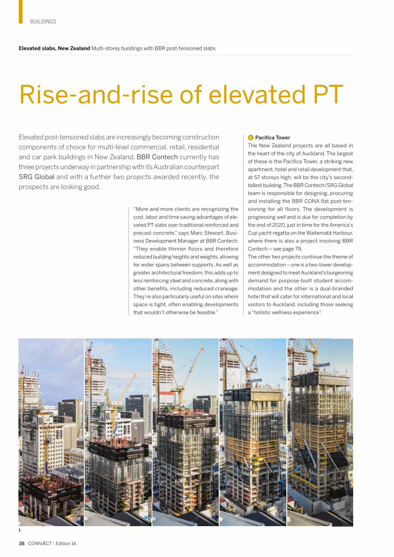
38 CONNÆCT | Edition 14
BUILDINGS
Elevated slabs, New Zealand Multi-storey buildings with BBR post-tensioned slabs
Rise-and-rise of elevated PT
Elevated post-tensioned slabs are increasingly becoming construction
components of choice for multi-level commercial, retail, residential
and car park buildings in New Zealand. BBR Contech currently has
three projects underway in partnership with its Australian counterpart
SRG Global and with a further two projects awarded recently, the
prospects are looking good.
1 Pacifica Tower
The New Zealand projects are all based in
the heart of the city of Auckland. The largest
of these is the Pacifica Tower, a striking new
apartment, hotel and retail development that,
at 57 storeys high, will be the city’s second-
tallest building. The BBR Contech/SRG Global
team is responsible for designing, procuring
and installing the BBR CONA flat post-ten-
sioning for all floors. The development is
progressing well and is due for completion by
the end of 2020, just in time for the America’s
Cup yacht regatta on the Waitemata Harbour,
where there is also a project involving BBR
Contech – see page 79.
The other two projects continue the theme of
accommodation – one is a two-tower develop-
ment designed to meet Auckland’s burgeoning
demand for purpose-built student accom-
modation and the other is a dual-branded
hotel that will cater for international and local
visitors to Auckland, including those seeking
a “holistic wellness experience”.
“More and more clients are recognizing the
cost, labor and time saving advantages of ele-
vated PT slabs over traditional reinforced and
precast concrete,” says Marc Stewart, Busi-
ness Development Manager at BBR Contech.
“They enable thinner floors and therefore
reduced building heights and weights, allowing
for wider spans between supports. As well as
greater architectural freedom, this adds up to
less reinforcing steel and concrete, along with
other benefits, including reduced craneage.
They’re also particularly useful on sites where
space is tight, often enabling developments
that wouldn’t otherwise be feasible.”
1

www.bbrnetwork.com 39
BUILDINGS
2 Student accommodation
The two-tower development, featuring towers
of 17 and 18 storeys, is located in the center of
the Auckland University of Technology cam-
pus. Once complete it will offer 641 self-catered
apartments for students, as well as retail and
hospitality services and student facilities that
include fitness centers, a basketball court and
a health and wellness center.
The BBR Contech/SRG Global partnership
is installing 33 floors, post-tensioned with
BBR VT CONA CMF S2 tendons, at one pour
per floor, spanning a total area of 14,078m2
– and it’s keeping them busy, as completion
is due before the first semester of 2021.
3 First of a kind hotel
Across town, work has begun on a new 490-
room, 39-storey hotel which will house a
290-room Holiday Inn Express on the lower
levels and a 200-room Even Hotel above. The
requirement here is for a total of 21,562m2 of
elevated post-tensioned flooring.
The Even Hotel will be the first of its kind out-
side North America and the first of a planned
10-15 hotels in Australasia. It offers a unique
four-star package of pampering founded on
an “eat well, rest easy, keep active” philoso-
phy that includes best-in-class fitness facilities,
aromatherapy amenities, in-room exercise
zones and nutritionally healthy menus.
The BBR Contech/SRG Global team, together
with concrete construction and formwork spe-
cialist Marin Construction, is responsible for
designing and coordinating the installation of
the elevated PT floors.
Given Auckland Council’s commitment to
urban intensification, there are likely to be
more exciting opportunities for this construc-
tion approach.
1 Time-lapse images showing the rise of Pacifica
Tower, from left to right, in July 2018, October
2018, February 2019, April 2019 and May 2019.
2 Visualization of the two completed towers of
student accommodation on the Auckland
University of Technology campus where the
BBR Contech/SRG Global partnership is
installing 33 post-tensioned floors.
TEAM & TECHNOLOGY
1 PACIFICA TOWERDeveloper – Hengyi Pacific
Architect – Plus Architecture
Main contractor – Icon Co Pty (NZ) Ltd
Technology – BBR CONA flat
BBR Network Members – BBR Contech (New Zealand) & SRG Global (Australia)
2 STUDENT ACCOMMODATIONDeveloper – Cedar Pacific
Architect – Marchese Partners
Main contractor – Icon Co Pty (NZ) Ltd
Technology – BBR VT CONA CMF flat
BBR Network Members – BBR Contech (New Zealand) & SRG Global (Australia)
3 HOLIDAY INN EXPRESS AND EVEN HOTELDeveloper – Pro-Invest
Architect – SJB
Main contractor – Icon Co Pty (NZ) Ltd
Technology – BBR VT CONA CMF flat
BBR Network Members – BBR Contech (New Zealand) & SRG Global (Australia)
2

40 CONNÆCT | Edition 14
BUILDINGS
Powerhouse Telemark, Norway BBR VT CONA CMM PT for suspended slabs & beams
The Green Diamond
A new generation of ‘energy positive buildings’ is springing up in Norway.
The aim is that they should generate more energy than they will consume
during their lifetime. With such credentials, it is therefore appropriate that
lean and green BBR post-tensioning technology has been chosen for the
floor slabs. Kristoffer Kalland, Project Manager for BBR Network Member
KB Spennteknikk AS, takes us through the philosophy and creation of the
spectacular Powerhouse Telemark project.
1
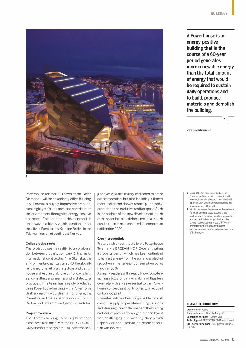
www.bbrnetwork.com 41
BUILDINGS
1 Visualization of the completed 11-storey
Powerhouse Telemark structure which will
feature beams and slabs post-tensioned with
BBR VT CONA CMM monostrand technology.
Image courtesy of Snøhetta.
2 Night-time view of the completed Powerhouse
Telemark building, set to become a local
landmark with its ‘energy positive’ approach
and reduced carbon footprint – the latter
strongly supported by the use of PT which
promotes thinner slabs and thus less
requires less concrete. Visualization courtesy
of R8 Property.
TEAM & TECHNOLOGY
Owner – R8 Property
Main contractor – Skanska Norge AS
Consulting engineer – Asplan Viak
Technology – BBR VT CONA CMM monostrand
BBR Network Member – KB Spennteknikk AS (Norway)
A Powerhouse is an energy-positive building that in the course of a 60-year period generates more renewable energy than the total amount of energy that would be required to sustain daily operations and to build, produce materials and demolish the building.
www.powerhouse.no
2
Powerhouse Telemark – known as the Green
Diamond – will be no ordinary office building.
It will create a hugely impressive architec-
tural highlight for the area and contribute to
the environment through its ‘energy positive’
approach. This landmark development Is
underway in a highly visible location – near
the city of Porsgrunn’s Kulltang Bridge in the
Telemark region of south east Norway.
Collaborative roots
The project owes its reality to a collabora-
tion between property company Entra, major
international contracting firm Skanska, the
environmental organization ZERO, the globally
renowned Snøhetta architecture and design
house and Asplan Viak, one of Norway’s larg-
est consulting engineering and architectural
practices. This team has already produced
three Powerhouse buildings – the Powerhouse
Brattørkaia office building in Trondheim, the
Powerhouse Drøbak Montessori school in
Drøbak and Powerhouse Kjørbo in Sandvika.
Project overview
The 11-storey building – featuring beams and
slabs post-tensioned with the BBR VT CONA
CMM monostrand system – will offer space of
just over 8,313m2 mainly dedicated to office
accommodation, but also including a fitness
room, locker and shower rooms, plus a lobby,
canteen and an exclusive rooftop space. Such
is the acclaim of the new development, much
of the space has already been pre-let although
construction is not scheduled for completion
until spring 2020.
Green credentials
Features which contribute to the Powerhouse
Telemark’s BREEAM NOR Excellent rating
include its design which has been optimized
to harvest energy from the sun and projected
reduction in net energy consumption by as
much as 66%.
As many readers will already know, post-ten-
sioning allows for thinner slabs and thus less
concrete – this was essential to the Power-
house concept as it contributes to a reduced
carbon footprint.
Spennteknikk has been responsible for slab
design, supply of post-tensioning tendons
and stressing. Due to the shape of the building
and lack of parallel slab edges, tendon layout
was challenging but, working closely with
Asplan Viak and Skanska, an excellent solu-
tion was devised.

42 CONNÆCT | Edition 14
BUILDINGS
Urban regeneration, Western Australia Solutions with versatile BBR post-tensioning systems & services
Great innings for BBR
Just a mention of ‘The Oval’ is sure to capture the attention of cricket
fans worldwide. However, for BBR Network Member SRG Global, any
recent conversation including these two words is all about construction
– at the Subiaco Oval and the Claremont Oval. Mahesh Nayak reports
on two high-scoring regeneration projects currently underway in
Western Australia.
Both of SRG Global’s projects are part of more
extensive renewal schemes – one is for a com-
mercial and residential development and the
other is for a brand new secondary school.
1 Claremont on the Park
Claremont on the Park is an inner city urban
regeneration development in western Perth
that is transforming under-utilized land areas
around the existing Claremont Oval by creat-
ing opportunities for high density residential
and commercial building developments. The
9.4-hectare site is a master-planned project
that will deliver more than 750 homes for about
2,000 future residents.
Claremont Oval is an Australian Rules Football
(AFL) stadium located in Perth which origi-
nally opened in 1905. The new development
will see the Claremont Football Club’s ground
and facility at the heart of the precinct with
new residences and businesses overlooking
the historic football oval. The development
also includes a significant amount of public
open space to promote foot traffic and access
to local facilities connecting the community
across the railway tracks.
Specialist services
BBR Network Member for Australia, SRG
Global, delivered the post-tensioning works
on this project which included the coordi-
nation and development of shop drawings
to PT design, supply, installation, stress-
ing and grouting of 240t of BBR CONA flat
post-tensioning.
Suspended slabs associated with Lots 504
& 505 were post-tensioned (Basement 1 to
Level 7) to accommodate car parking and
234 apartment units. In order to allow asso-
ciated structural movements, we installed
over 6,500 TMJ (temporary movement joint)
dowels and subsequently grouted them.
Project challenges
Project challenges included extensive coor-
dination during development of PT shop
drawings with designers and other related
trades, logistics associated with just-in-time
material deliveries and on site coordination
of activities, as the works were simultaneously
carried out on both blocks and at multiple
fronts to meet the construction schedule.
SRG Global’s ability to source materials in
large volumes coupled with its in-house pro-
duction facility of specialist items helped to
contain project cost inflation associated with
an additional scope of works entrusted during
its design development.
1
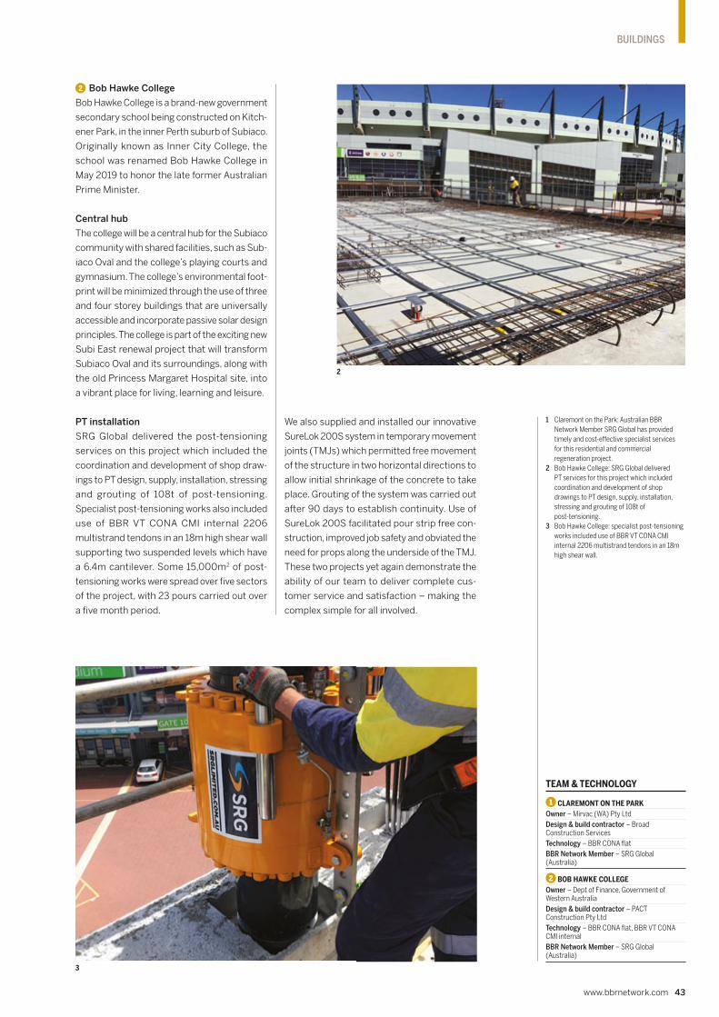
www.bbrnetwork.com 43
BUILDINGS
2 Bob Hawke College
Bob Hawke College is a brand-new government
secondary school being constructed on Kitch-
ener Park, in the inner Perth suburb of Subiaco.
Originally known as Inner City College, the
school was renamed Bob Hawke College in
May 2019 to honor the late former Australian
Prime Minister.
Central hub
The college will be a central hub for the Subiaco
community with shared facilities, such as Sub-
iaco Oval and the college’s playing courts and
gymnasium. The college’s environmental foot-
print will be minimized through the use of three
and four storey buildings that are universally
accessible and incorporate passive solar design
principles. The college is part of the exciting new
Subi East renewal project that will transform
Subiaco Oval and its surroundings, along with
the old Princess Margaret Hospital site, into
a vibrant place for living, learning and leisure.
PT installation
SRG Global delivered the post-tensioning
services on this project which included the
coordination and development of shop draw-
ings to PT design, supply, installation, stressing
and grouting of 108t of post-tensioning.
Specialist post-tensioning works also included
use of BBR VT CONA CMI internal 2206
multistrand tendons in an 18m high shear wall
supporting two suspended levels which have
a 6.4m cantilever. Some 15,000m2 of post-
tensioning works were spread over five sectors
of the project, with 23 pours carried out over
a five month period.
1 Claremont on the Park: Australian BBR
Network Member SRG Global has provided
timely and cost-effective specialist services
for this residential and commercial
regeneration project.
2 Bob Hawke College: SRG Global delivered
PT services for this project which included
coordination and development of shop
drawings to PT design, supply, installation,
stressing and grouting of 108t of
post-tensioning.
3 Bob Hawke College: specialist post-tensioning
works included use of BBR VT CONA CMI
internal 2206 multistrand tendons in an 18m
high shear wall.
TEAM & TECHNOLOGY
1 CLAREMONT ON THE PARKOwner – Mirvac (WA) Pty Ltd
Design & build contractor – Broad Construction Services
Technology – BBR CONA flat
BBR Network Member – SRG Global (Australia)
2 BOB HAWKE COLLEGEOwner – Dept of Finance, Government of Western Australia
Design & build contractor – PACT Construction Pty Ltd
Technology – BBR CONA flat, BBR VT CONA CMI internal
BBR Network Member – SRG Global (Australia)
We also supplied and installed our innovative
SureLok 200S system in temporary movement
joints (TMJs) which permitted free movement
of the structure in two horizontal directions to
allow initial shrinkage of the concrete to take
place. Grouting of the system was carried out
after 90 days to establish continuity. Use of
SureLok 200S facilitated pour strip free con-
struction, improved job safety and obviated the
need for props along the underside of the TMJ.
These two projects yet again demonstrate the
ability of our team to deliver complete cus-
tomer service and satisfaction – making the
complex simple for all involved.
2
3

44 CONNÆCT | Edition 14
BUILDINGS
1
New capital city, Egypt BBR VT CONA CMF flat post-tensioning for major schemes
Meeting demands of dynamic growth
The Egyptian construction market entered a dynamic growth phase following
the announcement in March 2015 by the Egyptian Government of expansive
plans for a new capital city, as well as the creation of three further new cities.
Mohamad Al-Shal, Business Development Manager of Cairo-based BBR
Network Member ESPT, provides some further background and an overview
of his company’s growing portfolio of work on this prestigious scheme.

www.bbrnetwork.com 45
BUILDINGS
The new city – which will be the new admin-
istrative and financial capital of Egypt – is
under construction some 45km to the east of
Cairo, bounded on the north by the Cairo to
Suez road and by the Cairo to Al Ain Sokhna
road to the south. It will house the main govern-
ment departments and ministries, as well as
over 50 foreign embassies. Designed to relieve
congestion in Cairo, the city covers an area of
700km2 and is expected to have a population
of between five to seven million people.
The scheme’s consultants have utilized every
possible technique across the whole new
administrative capital city site to meet the Gov-
ernment’s vision of a 2023 completion date. For
example, they have embraced post-tensioning
for the construction of governmental and resi-
dential buildings, as well as precast prestressed
construction for sporting facilities such as the
seven 40,000 seat stadiums. The majority of
construction work will be for commercial, office
and residential facilities where post-tensioned
concrete has been chosen for almost every
project – to deliver larger living or working
spaces, along with a fast construction program.
Vision for finest technology
The use of European approved post-tensioning
technology for the new capital city project
had been stipulated by the local consulting
engineers. In a direct response to this, ESPT
was established in December 2018. Our new
business can now not only draw on around
12 years’ experience from within its parent
company, the e-solution Construction &
Engineering group, but also benefit from the
strengths of the BBR Network.
The vision of the company’s founders, Amr
Al-Taher, Mohammed Ashour and Mohammed
Ayad, was to create a specialist construction
engineering unit, based on latest European
approved BBR technology, along with existing
skills in tilt-up and other concrete construction
techniques. This vision is being realized with
the support of BBR VT International who, as
ETA holder, facilitated the approval stage with
the local consulting engineers. In fact, seeing
the potential for even greater business oppor-
tunities, marketing activities actually began
during the final stage of contract negotiations
with BBR VT International.
First project award
Our first project award was for a cluster in
Zone 06, a 100,000m2 residential project
which was forecast to require some 500t of
prestressing steel over an 18-month period.
After contract award, the design and con-
struction team worked simultaneously. Design
activities for the layout of the BBR VT CONA
CMF flat PT tendons ran in parallel with placing
orders and on-site mobilization. We wanted
to be ready to provide the main contractor
with extended services before casting of the
columns to support the basement slab. In
addition, BIM models processed by Marwa
Rami were supplied to the main contractor to
smooth the coordination.
In less than 45 days, our design team, led
by Mona Al-Kersh, completed the design for
all seven structures, as all the buildings are
founded on one shared basement and ground
slab. In the basement and at ground floor level,
the total slab area was 20,000m2. The project
is part of larger residential development with
a total area of 700,000m2 of post-tensioned
slabs in seven clusters.
2 3

46 CONNÆCT | Edition 14
BUILDINGS
Second success
Just two months after our first slab was cast,
we were awarded a second cluster contract,
again based on using the CONA CMF PT sys-
tem. This added a further 500t of prestressing
steel – and another victory over our compet-
itors – to our portfolio. Our challenges then
were to continue working closely with our client
to resolve issues on site as quickly as possible
and to ensure that deliveries to site arrived in
time to keep construction activities moving
ahead on program.
It was vital that mobilization and supply chain
activities ran smoothly as both the main con-
tractor and consultant were handling many
other developments in the same area. We
have really appreciated the excellent supply
chain support, while the seminars and training
sessions organized by the BBR Headquarters
team added much value to the whole process.
Future growth
The ESPT development team is now building
on the practical advice offered and useful
presentations given by the BBR Headquar-
ters team and is forging further connections
with clients. The marketing effort has already
brought an additional contract, requiring 600t
of prestressing steel, in a neighboring devel-
opment in the new administrative capital. Our
development team was able to use the success
achieved in the first two clusters, in Zone 06,
as a showcase to clients of how quickly we
could mobilize site teams, organize supplies
and produce designs.
Meanwhile, back at Zone 06, the main con-
tractor awarded us an additional contract
– involving a further 500t of prestressing steel.
This brings our total supply and install scenario
to 1,500t of prestressing steel across three
clusters in less than six months from receiving
the first contract award.
Our site team, led by Mohammed Rizk, is
meeting all the challenges of these major
post-tensioning projects with great profes-
sionalism. The excellent work of our site team
and design department, backed by the quality
of the BBR technology, service and support,
has placed us in a strongly competitive posi-
tion with regard to winning further contracts.
Even in the face of fierce competition in our
marketplace here, we are confident that we
will be able to announce many more contract
awards in the coming months.
1 View across part of the construction site for
the new Egyptian capital city showing one of
the projects currently being carried out there
by BBR Network Member ESPT.
2 Overview of the Zone 06 construction site
which is expected to require some 500t of
prestressing steel over an 18-month period.
3 Visualization of part of the cluster in Zone 06,
where ESPT has been supporting the main
contractor with post-tensioning design using
the BBR VT CONA CMF flat system and
construction services for a 100,000m2
residential project.
4 Support from the BBR Headquarters team
with marketing activities such as on our
exhibition stand at the Big Five Construct
Conference in Cairo, has helped ESPT to win
more work.
5 BBR Headquarters and ESPT team members
during a site visit to the new Egyptian capital
city. Left to right: Cezary Sternicki, Ahmed
Albarbary, Daniel Cuerdo, Mohamad AlShal,
Moamen Eltawel & Mohammed Rizk.
TEAM & TECHNOLOGY
Client – New Administrative Capital
Main contractors – Hassan Allam Construction
Consulting engineer – ECG consultant
Technology – BBR VT CONA CMF flat
BBR Network Member – ESPT (Egypt)
4
5

www.bbrnetwork.com 47
BUILDINGS
The record-breaking floor which covers an
area of 7.4 hectares – the equivalent of over
seven rugby pitches – will be part of a new
distribution center being built by Auckland
International Airport for Foodstuffs, New
Zealand’s biggest grocery distributor and
one of the country’s largest organizations.
Produce will be kept at ambient temperature
in the warehouse and then shipped to stores
throughout the upper North Island.
Use of the BBR VT CONA CMF S2 flat system
with its optimized componentry including
universal mono barrel anchorages, simplified
load bearing components and minimal need
for reinforcement streamlined the installation
and allowed the site team to make excellent
progress against schedule.
Over the years, BBR Contech has become a
market leader with its expertise in constructing
leading edge, low maintenance ground slabs.
A combination of excellent partnerships with
concrete specialists and latest BBR post-
tensioning technology has further supported
the company’s achievements.
Distribution warehouse, Auckland, New Zealand First use of CONA CMF S2 slab system in NZ
Double landmark
BBR Contech is celebrating two landmarks in one project – a contract to
design the largest-yet post-tensioned floor slab in New Zealand and the
chance to use the BBR VT CONA CMF S2 slab system for the first time.
TEAM & TECHNOLOGY
Owner – Auckland International Airport Ltd
Main contractor – Macrennie Commercial Construction
Floor contractor – Conslab
Structural engineer – Tony Day Consultants
Technology – BBR VT CONA CMF flat
BBR Network Member – BBR Contech (New Zealand)
1
1 The BBR VT CONA CMF S2 system with its
optimized componentry including universal
mono barrel anchorages, simplified load
bearing components and minimal need for
reinforcement streamlined the installation
of this record-breaking 7.4 hectare floor.
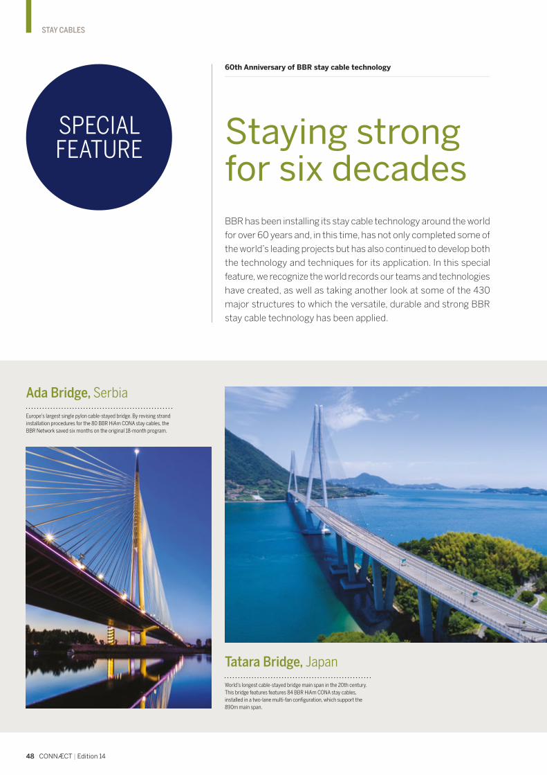
Ada Bridge, Serbia
Europe's largest single pylon cable-stayed bridge. By revising strand
installation procedures for the 80 BBR HiAm CONA stay cables, the
BBR Network saved six months on the original 18-month program.
Tatara Bridge, Japan
World’s longest cable-stayed bridge main span in the 20th century.
This bridge features features 84 BBR HiAm CONA stay cables,
installed in a two-lane multi-fan configuration, which support the
890m main span.
48 CONNÆCT | Edition 14
STAY CABLES
BBR has been installing its stay cable technology around the world
for over 60 years and, in this time, has not only completed some of
the world’s leading projects but has also continued to develop both
the technology and techniques for its application. In this special
feature, we recognize the world records our teams and technologies
have created, as well as taking another look at some of the 430
major structures to which the versatile, durable and strong BBR
stay cable technology has been applied.
Staying strong for six decades
SPECIAL FEATURE
60th Anniversary of BBR stay cable technology
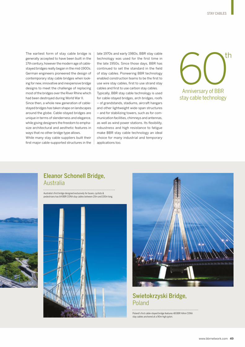
Swietokrzyski Bridge, Poland
Poland's first cable-stayed bridge features 48 BBR HiAm CONA
stay cables anchored at a 90m high pylon.
Eleanor Schonell Bridge, Australia
Australia's first bridge designed exclusively for buses, cyclists &
pedestrians has 64 BBR CONA stay cables between 20m and 100m long.
www.bbrnetwork.com 49
STAY CABLES
The earliest form of stay cable bridge is
generally accepted to have been built in the
17th century, however the modern age of cable-
stayed bridges really began in the mid-1900s.
German engineers pioneered the design of
contemporary stay cable bridges when look-
ing for new, innovative and inexpensive bridge
designs to meet the challenge of replacing
most of the bridges over the River Rhine which
had been destroyed during World War II.
Since then, a whole new generation of cable-
stayed bridges has taken shape on landscapes
around the globe. Cable-stayed bridges are
unique in terms of slenderness and elegance,
while giving designers the freedom to empha-
size architectural and aesthetic features in
ways that no other bridge type allows.
While many stay cable suppliers built their
first major cable-supported structures in the
late 1970s and early 1980s, BBR stay cable
technology was used for the first time in
the late 1950s. Since those days, BBR has
continued to set the standard in the field
of stay cables. Pioneering BBR technology
enabled construction teams to be the first to
use wire stay cables, first to use strand stay
cables and first to use carbon stay cables.
Typically, BBR stay cable technology is used
for cable-stayed bridges, arch bridges, roofs
– of grandstands, stadiums, aircraft hangars
and other lightweight wide-span structures
– and for stabilizing towers, such as for com-
munication facilities, chimneys and antennas,
as well as wind power stations. Its flexibility,
robustness and high resistance to fatigue
make BBR stay cable technology an ideal
choice for many industrial and temporary
applications too.
Anniversary of BBR stay cable technology

1 2000 – world’s first combined arch and stay
cable bridge spanning a lake, Seri Saujana
Bridge, Putrajaya, Thailand. The 42m high
pylon forms the upper anchorage point for
the 84 BBR CONA STAY cables.
2 2011 – world’s first stay cable bridge
incorporating a railway station – Basarab
Bridge, Bucharest, Romania. This is a five span
cable-stayed bridge with 60 BBR HiAm CONA
stay cables and also features BBR VT CONA
CMI internal post-tensioning.
3 1997 – longest bridge in Finland, the
Raippaluoto, or Replot, Bridge – features 64
BBR HiAm CONA stay cables anchored at two
A-shaped concrete pylons. Given the harsh
subarctic winter conditions here, the concept
of factory prefabricated stay cables proved
invaluable to timely project completion.
4 1960 – world’s first parallel wire stay cables
– Schillersteg (now known as Ferdinand
Leitner Steg) in Stuttgart, Germany. The 10
BBR stay cables, encapsulated in a
polyethylene pipe and injected with cement
grout, are still performing well – 60 years after
their installation. Image courtesy of Landesamt
für Denkmalpflege im Regierungspräsidium
Stuttgart, photograph by Felix Pilz.
5 1994 – world’s first combined stay cable &
floating bridge – Nordhordland Bridge, Bergen,
Norway. The cable-stayed span features 48
BBR HiAm CONA stay cables and is connected
to the floating part of the bridge by a transition
pier. Image by Kim Rasmussen, licensed under
CC BY-SA 3.0, via Wikimedia Commons.
50 CONNÆCT | Edition 14
STAY CABLES
60th Anniversary of BBR stay cable technology Stay cable bridges
Since the 1950s, cable-stayed bridges have
been built in ever increasing numbers and are
especially suitable for medium to long spans
of 100 to 1,000m, where this solution can
deliver technical and economic advantages.
Their advantages lie mainly in increased
aerodynamic stability, reduced costs for the
abutments, easier construction and light
overall structures. For smaller bridges, other
parameters may be decisive in the choice of
a cable-stayed solution – such as reduced
depth of deck, construction methodology
and aesthetics.
First BBR stay cables
The earliest stay cable technology available
to provide the required static strength and
high amplitude fatigue resistance was parallel
wire cables. The first installation of such high
amplitude fatigue resistant wire cables was
carried out by BBR in 1960 on the Schillersteg
bridge in Stuttgart, Germany.
Now officially known as the Ferdinand-Leitner
Steg, the 100m long pedestrian bridge was
conceived as an architectural centerpiece
and a link across a main road between the
two sections of the 1961 Federal Garden Show.
Bridges connect people and places, as well as providing continuity of travel –
they can bring vital economic and social advantages too. In the case of a stay
cable bridge, other quite special opportunities arise – such as making bold
architectural statements or creating new emblems for cities or definitions for
landscapes. As the global demand for infrastructure has grown and evolved, so
too has BBR stay cable technology which includes the finest products available.
Making new connections
1
2 3

www.bbrnetwork.com 51
STAY CABLES
The 10 BBR wire stay cables consist of bundles
of up to 90 parallel 6mm diameter prestress-
ing wires encapsulated in a polyethylene pipe
and injected with cement grout. While the
heritage-listed bridge has received major
refurbishment generally, ultrasound testing
has shown that the BBR stay cables are still
performing well.
The concept of connecting people with cultural
spaces via stay cable bridges has continued
down the years – such as Bell’s Bridge over
the River Clyde in Glasgow, Scotland and more
recently, Assut de l’Or (or Serreria) Bridge in
Valencia, Spain.
High amplitude fatigue resistant strand stay
cables found their first major application in
the early 1970s for the new Olympic Stadium
in Munich with its cable-supported membrane
roof structure, subjected to high cyclic wind
loads. Even while work was still underway
in Munich, the BBR HiAm CONA stay cable
system was also being applied to the Kurt
Schumacher Bridge in Mannheim.
Types of stay cable
As wire stay cables are generally prefabricated
and strand stay cables are more commonly
assembled on site using the strand-by-strand
installation method, the choice of the most
suitable cable system for a particular project
depends on many factors.
It has often been considered that prefabri-
cated cables are best suited to smaller bridges.
On site fabricated stay cables are usually
suited to longer spans. However, each proj-
ect should be individually evaluated – taking
into account erection requirements and the
overall economics.
World leading BBR stay cable technology
Today, with its superior fatigue resistance
and high corrosion protection, the BBR HiAm
CONA parallel strand stay cable system rep-
resents state-of-the-art technology. It is the
best product on the international market
place – with the highest capacity, most com-
pact and widest range of anchorages available.
As with all BBR technologies, the BBR HiAm
CONA system has been thoroughly tested
– to parameters exceeding the traditional
requirements of fib and PTI criteria – and is
continuously maintained by BBR engineers in
Switzerland. When this pedigree is combined
with the installation expertise of the BBR Net-
work, backed by the Engineering and Special
Projects Team from the Swiss BBR Headquar-
ters, the BBR HiAm CONA system is simply
unrivaled anywhere on the planet.
1960 World’s first use of wire stay
cables – Schillersteg, Stuttgart,
Germany
1971 World’s first high amplitude wire
stay cable bridge – Kurt-Schumacher
Bridge, Mannheim, Germany
1972 World's largest roof supported
with strand stay cables – Munich
Olympic Stadium, Germany
1977 World’s first long span
cable-stayed railway bridge – Zarate
Largo Bridges, Argentina
1977 World’s first earth-anchored
cable-stayed bridge – Indiano Bridge,
Florence, Italy
1978 World’s first cable-net supported
tower – Sydney Tower, Australia
1988 World's longest cable-stayed
pedestrian swing bridge – Bell’s
Bridge, Glasgow, Scotland
1987 World’s longest transit
skytrain-only bridge – ALRT Skybridge,
Canada
1994 World’s first combined stay
cable & floating bridge – Nordhordland
Bridge, Bergen, Norway
1996 World’s first bridge to use
carbon stay cable technology –
Storchenbrücke, Switzerland
1999 World’s longest cable-stayed
bridge span in 20th Century – Tatara
Bridge, Japan
2000 World’s first combined arch
and stay cable bridge spanning a lake
– Seri Saujana Bridge, Putrajaya,
Thailand
2005 World’s longest free span &
curved stay cable bridge – Langkawi
Skybridge, Malaysia
2005 World’s first cable-stayed
bridge to be built twice & world’s
largest cable-stayed bridge
reconstruction project – Sloboda
Bridge, Novi Sad, Serbia
2011 World’s first stay cable bridge
incorporating a railway station –
Basarab Bridge, Bucharest, Romania
World Recordswith BBR stay cables
4 5

Often described as a cross between a box-girder bridge and a cable-
stayed bridge, extradosed bridges have been built in increasing
numbers since the 1980s. As their popularity steadily grew, so the
BBR HQ team developed and launched the new BBR HiEx CONA
saddle system to completely overcome the challenges associated with
standard friction saddles. In this article, we examine the extradosed
bridge concept, look at some projects and delve deeper into the
BBR technology.
60th Anniversary of BBR stay cable technology Extradosed bridges
Extra special bridge structures
Extradosed bridges are a hybrid type of bridge
believed to have first appeared in the 1980s.
The most obvious difference between a cable-
stayed bridge and an extradosed bridge is
that the latter has a self-supporting deck.
The extradosed bridge type was a favored style
of the late great Christian Menn, an outstand-
ing bridge engineer and close friend of the
BBR Network. One of the most famous bridges
created with his insight and BBR technology
was the award-winning Sunniberg Bridge,
near Klosters in Switzerland.
52 CONNÆCT | Edition 14
STAY CABLES
1
2 3

www.bbrnetwork.com 53
STAY CABLES
* The minimum radius of the BBR HiEx CONA Bundle Saddle configuration depends on the degree of filling and maximum contact pressure permitted at the place of use.
1 The extradosed design of the Puch Bridge
over the River Drava in Ptuj, Slovenia featured
BBR VT CONA CMI and CONA CME, internal
and external, post-tensioning tendons.
2 The New Europe Bridge crosses the River
Danube between Romania and Bulgaria.
The construction of this massive bridge
featured the first use of the BBR HiEx CONA
saddle system.
3 Sunniberg Bridge, near Klosters in Switzerland
– an extradosed bridge project involving both
Christian Menn and BBR technology. The
bridge was presented with the 2001 IABSE
Outstanding Structure Award.
4 Image showing the two configurations in which
the BBR HiEx CONA saddle is available. On the
left, is the BBR HiEx CONA Monotube Saddle
and on the right is the BBR HiEx CONA Bundle
Saddle. This solution ensures no slippage and
full load transmission between the stay cable
and the saddle. It overcomes problems
associated with standard friction saddles
while, at the same time, allows for a compact
and slender pylon.
BENEFITS OF BBR HiEx CONA SADDLE
Zero fretting fatigue at any point in the saddle
Very low minimum radius of curvature of 2.0m
Allows compact & slender pylon
No slippage and full load transmission between stay cable & saddle at all times
Inspection/replacement of individual strands
Highest level of corrosion protection
Design advantages
Depending on the specific situation, extradosed
bridges might offer advantages including:
• cost savings – for medium length bridges
• reduced tower height – in proximity to
airports, for example
• reduced girder depth – enabling a longer
span without impacting bridge deck profile.
With a typical cable-stayed bridge, most of the
live load – from vehicular traffic – is carried
through the stay cables, while the rest is sup-
ported by the deck. In an extradosed bridge,
due to the higher stiffness of the deck, the
proportions are significantly reduced allow-
ing for a more equal redistribution of the
loads and lower live loads transferring to the
stays. This offers great advantages in terms
of reducing the effects of fatigue on the stays
and the anchorages, increasing the material
efficiency level.
The deck of an extradosed bridge is directly
supported by resting on part of the tower – so
that, in close proximity to the tower, the deck
can act as a continuous structural element.
In extradosed bridges, the stay cables are con-
tinuous and pass, via a saddle, over the top
of the bridge piers. The tension exerted by
the cables acts more to compress the bridge
deck horizontally than to support it vertically,
because of the lower angles of intersection with
the tower and deck. The cable stays thus act
as prestressing cables for the concrete deck.
The end result is a highly efficient load-bearing
bridge, with striking visual qualities offered by
the exposed cables and concrete towers above
the road surface.
Saddle system solution
The BBR HiEx CONA saddle system comp-
letely eliminates the problems associated
with standard friction saddles and, at the same
time, allows for a compact and slender pylon.
Unlike traditional friction saddles – that try
to compensate differential cable forces with
friction between the strand and the inner sad-
dle material – the HiEx CONA saddle is a fixed
structural point which ensures no slippage
and full load transmission between the stay
cable and the saddle. The technical solution
results from the combination of the European
Approved CONA CMI internal post-tension-
ing system with the HiAm CONA strand stay
cable system.
Creating global dialogues
One of the reasons that BBR technologies
have remained relevant and sought after over
the years is that BBR has always participated
in international dialogues about improving
construction technology and techniques. Most
recently, we contributed to the new fib Bulletin
89: Acceptance of stay cable systems using
prestressing steels, issued in 2019 – this is
directly relevant to extradosed bridges.
Strand
Bundle
Socket
BBR HiAm CONA
Nut Head
Cap
CONA CMI Square Plate
or Bearing Trumplate
BBR HiEx CONA
Monotube Saddle BBR HiEx CONA
Bundle Saddle
BBR HiEx CONA
Sleeve-W
Pylon
HDPE PipeSBR *≥ 2.0m
4

54 CONNÆCT | Edition 14
STAY CABLES
Almonte Viaduct Extramadura, Spain
Completed in 2016, the 996m long Almonte Via-
duct is the most prominent structure on the AVE
high speed railway line from Madrid to Extremad-
ura which will connect Spain and Portugal. The
viaduct holds the world record for having the lon-
gest span for an arched high speed railway bridge.
For the construction of the arch, a total of 208
BBR HiAm CONA 5506 and 3706 stay cables
were used as temporary supports while the arch
segments were being cast in sequence. With
the concreting of the final segment, the arch
became self-supporting and the stay cables were
progressively and carefully de-stressed before
being dismantled.
The strength and special techniques associated with BBR
stay cable technology have, over the years, been harnessed
to support the construction of several arch bridge projects.
BBR Network Members’ use of stay cables in these situations
substantially reduced the need for expensive temporary
works, minimized environmental impacts and contributed
to program savings too. After completion of the projects
the stay cables were carefully de-stressed and dismantled,
following preplanned sequences and involving structural
calculations and checks. Today, these bridges stand proud in
their landscapes – and perhaps only they, and their creators,
can testify to the secret behind their realization.
60th Anniversary of BBR stay cable technology
Efficient temporary works with stay cables
Secrets of success
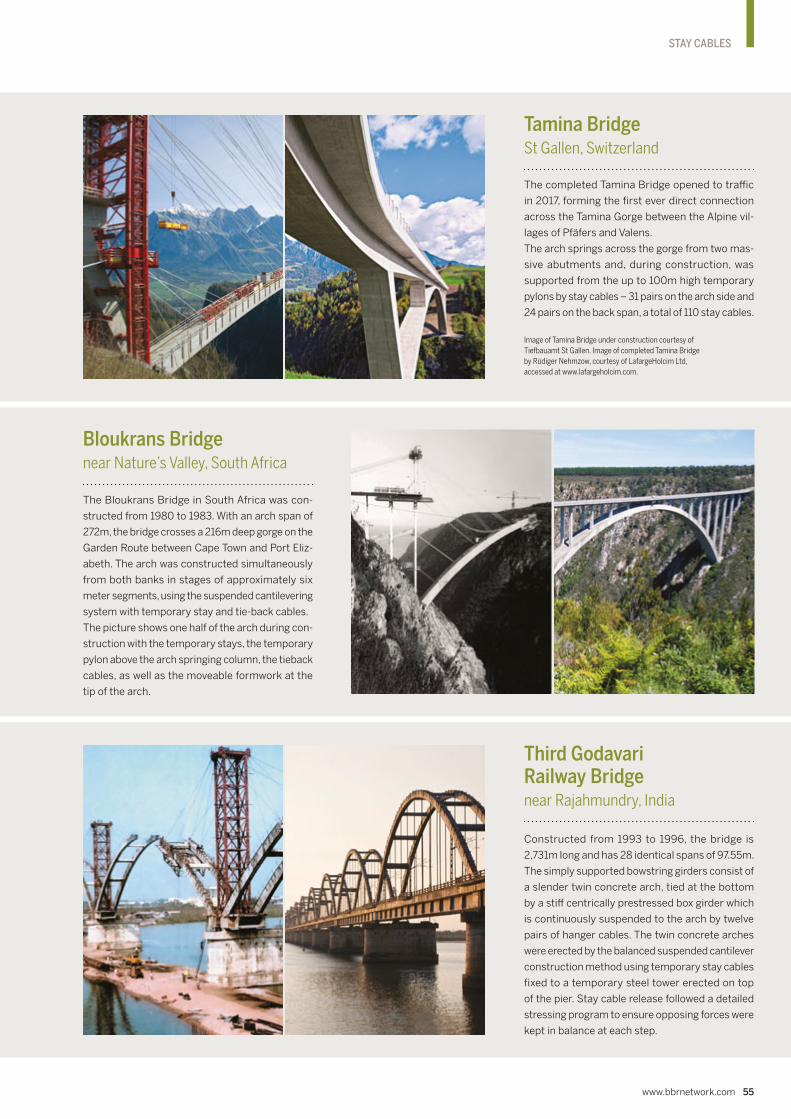
www.bbrnetwork.com 55
STAY CABLES
Bloukrans Bridge near Nature’s Valley, South Africa
The Bloukrans Bridge in South Africa was con-
structed from 1980 to 1983. With an arch span of
272m, the bridge crosses a 216m deep gorge on the
Garden Route between Cape Town and Port Eliz-
abeth. The arch was constructed simultaneously
from both banks in stages of approximately six
meter segments, using the suspended cantilevering
system with temporary stay and tie-back cables.
The picture shows one half of the arch during con-
struction with the temporary stays, the temporary
pylon above the arch springing column, the tieback
cables, as well as the moveable formwork at the
tip of the arch.
Third Godavari Railway Bridge near Rajahmundry, India
Constructed from 1993 to 1996, the bridge is
2,731m long and has 28 identical spans of 97.55m.
The simply supported bowstring girders consist of
a slender twin concrete arch, tied at the bottom
by a stiff centrically prestressed box girder which
is continuously suspended to the arch by twelve
pairs of hanger cables. The twin concrete arches
were erected by the balanced suspended cantilever
construction method using temporary stay cables
fixed to a temporary steel tower erected on top
of the pier. Stay cable release followed a detailed
stressing program to ensure opposing forces were
kept in balance at each step.
Tamina Bridge St Gallen, Switzerland
The completed Tamina Bridge opened to traffic
in 2017, forming the first ever direct connection
across the Tamina Gorge between the Alpine vil-
lages of Pfäfers and Valens.
The arch springs across the gorge from two mas-
sive abutments and, during construction, was
supported from the up to 100m high temporary
pylons by stay cables – 31 pairs on the arch side and
24 pairs on the back span, a total of 110 stay cables.
Image of Tamina Bridge under construction courtesy of
Tiefbauamt St Gallen. Image of completed Tamina Bridge
by Rüdiger Nehmzow, courtesy of LafargeHolcim Ltd,
accessed at www.lafargeholcim.com.

1 2004 City Bridge, Newport, Wales – part of a 9.3km
bypass around the city, this 195m long bridge over the River
Usk was installed with 34 BBR stay cables.
2 2006 Pulao Bunting Bridge, Kedah, Malaysia – forming
part of a 2km access bridge from the Kedah coast to Bun-
ting Island, the 80m span bowstring arch bridge is stayed
with 26 BBR DINA wire stay cables and was floated into
position on barges.
3 2006 Navia River Bridge, Asturias, Spain – the twin
arches of this bridge are vertically inclined by 5° and were
designed to work in a curved plane. The structure features
34 pairs of BBR DINA stay cables, along with precast
segmental construction and both internal and external
BBR post-tensioning technology. The project won both the
2010 fib Outstanding Structure Award and the 2007 BBR
Network Project of the Year Award.
BBR stay cables – along with much other BBR
Network technology and know-how – have been
applied to bowstring arch bridges. This musical
sounding style of bridge is distinguished by its
arch which is ‘stringed’ like a musician’s bow,
with stay cables tying the arch to the bridge
deck – thus providing resistance to the upward
thrusting forces of the arch.
60th Anniversary of BBR stay cable technology Bowstring arch bridges
Orchestrated spans
56 CONNÆCT | Edition 14
STAY CABLES
3
1
2

www.bbrnetwork.com 57
STAY CABLES
1 Eight cable stays – with sockets weighing over 370kg
– were fabricated, installed and stressed to support
conveyors at the Mount Whaleback Mine Ore Handling
Facility in Newman, Western Australia. This huge weight
required new systems to be developed for the installation
of the stays. All stay cables were fabricated at ground level
and lifted into position.
2 A further eight cable stays were designed, supplied and
installed for the Karara Iron Ore Project, also in Western
Australia. Each BBR HiAm CONA stay cable consists of
a forked clevis connection at the top with an adjustable
lower anchorage. Here, the stay cables are permanently
loaded and support the cantilevered section of the stacking
conveyor. Loads are variable, according to conveyor belt
operating capacity, wind and seismic activity.
3 Meanwhile, on the other side of the country, in Mel-
bourne, stay cables are literally keeping the lid on things at
Melbourne Water’s Western Treatment Plant in Werribee.
A treatment lagoon cover – which captures biogas for
conversion to electricity – was being replaced. To secure the
cover in place, a series of 11 BBR HiAm CONA stay cables
which traverse the lagoon in a convex and concave pattern
were designed, supplied and installed.
BBR Network Members around the world
have developed a reputation for finding
innovative new ways to use BBR technology
and deliver solutions to customer challenges.
In recent years, three such challenges resulted
in unconventional, yet practical BBR stay
cable solutions.
60th Anniversary of BBR stay cable technology
Innovative solutions for industry
Industrial strength technology
3
1
2

58 CONNÆCT | Edition 14
STAY CABLES
The two structures have longevity in common
– both have exceeded the expectations of their
owners in terms of durability. They have also
been developed and reenergized to present
new challenges to the many visitors that flock
to see them every year. In Munich, visitors can
now take daily tours involving climbing and
abseiling from the famous ‘tented roofs’ of the
stadium built for the 1972 Olympic Games. The
stadium itself also hosts an impressive array
of concerts and many other events. Mean-
while, the Sydney Tower Eye offers tourists a
360 degree view of the city from its internal
observation deck, along with a new Skywalk
attraction featuring an open-air glass-floored
platform, as well as a 4D cinema experience.
In addition, each year there is a special charity
race event – Sydney Tower Stair Challenge –
when up to 750 entrants race up some 1,504
steps to get to the top of the tower.
Olympic Stadium Roof
The creative vision for the tented roof of Mun-
ich’s distinctive stadium lay in the concept of
unifying all the different spaces for the 1972
Olympic Games with a continuous, lightweight
and translucent roof. Architect Frei Otto, whose
earlier much smaller tented roof for the Ger-
man Pavilion at Expo ‘67 in Montreal served as
inspiration, collaborated with the Behnisch &
Partner architectural practice and the consult-
ing engineering firm founded by Fritz Leonhardt
and Wolfhart Andrä (now known as LAP) on
the massive cable-net roof project in Munich.
The then new BBR HiAm parallel strand stay
cable system – in total some 488 individual
stay cables – was installed to support the
almost 75,000m2 roof structure which covers
the west grandstand of the stadium, indoor
pool and gymnastic area. The stay cables are
anchored at cable-stayed towers which range
in height between 70 and 80m. In addition, the
stadium roof is tensioned by a single curved
parallel strand cable running along the inner
edge. All elements of the cable-net roof struc-
tures were first assembled on the ground and
then lifted into position.
Since 1998, along with the rest of the Olym-
pic Park, the stunning cable-net roof enjoys
the status of being a protected national
monument.
Any review of BBR stay cable achievements and capabilities would be incomplete without at least another brief look
at two now very familiar projects – the tented roof of the Olympic Stadium in Munich, Germany and the iconic Sydney
Tower in Australia. Both structures have not only stood the test of time, but they have also become ‘destinations’
offering experiences beyond their original purposes during their long lifetimes.
60th Anniversary of BBR stay cable technology Landmark structures
Standing the test of time

www.bbrnetwork.com 59
STAY CABLES
Sydney Tower
Like the Olympic Stadium in Munich, Sydney
Tower has become a much loved emblem of its
home city. Opened to the public in August 1981,
whichever way you look at it, Sydney Tower has
more than delivered on its promises for the
vibrant Australian city. Originally constructed
as a telecommunications tower and the defin-
ing architectural feature of the Centrepoint
commercial development, today – almost 40
years since its opening – the 309m high tower
still remains Sydney’s tallest structure.
Its unique supporting net structure, created
with BBR DINA stay cables, sets it apart
from the crowd. The steel tower rises 230m
above the roof of the central Sydney 12-level
office building. Its shaft is stayed by a system
of 56 BBR parallel-wire prestressing cables
arranged in a hyperboloid of revolution. The
tower is topped by a turret of five levels accom-
modating two revolving restaurants and two
observation decks.
Many comparisons have been made about
the dimensions of the tower. For the Global
BBR Network, the most interesting may be the
analogy that if the stay cables securing the
tower were laid end-to-end, they would stretch
some 2,395km – roughly the same distance
as Zurich to Ankara, or Oslo to Madrid and, in
fact, further than Auckland to Sydney, New
York to Houston and just a little further than
Singapore to Manila.
Skillful selection of the distribution of prestressing forces in the cable nets permitted, like no other building methodology, the achievement of as perfect an adaptation of the roof forms to the architects' idea and the diversity of the terrain and substructures, as was possible and necessary for the Olympic roof.
IABSE congress report (1972): Das Olympiadach in München, by Jörg Schlaich, H. Altmann, R. Bergermann, K. Gabriel, K. Horstkötter, K. Kleinhanss, P. Linhart, G. Mayr, J. Noesgen, U. Otto, H. Schmidt, Ingenieurbüro Leonhardt und Andrä, Stuttgart, Germany.
SCAN MEUse your smartphone to scan the
code and learn more about BBR
stay cable technology. Or visit
www.bbrnetwork.com/downloads/brochures and download the
brochure on the BBR HiAm CONA
strand stay cable system.

60 CONNÆCT | Edition 14
SPECIAL APPLICATIONS
Keepit Dam, owned and operated by WaterNSW, is
situated on the Namoi River, 30km upstream of
Gunnedah on the north west slopes of the New
South Wales Northern Tablelands. The 55m high
dam has a capacity of 425,000Ml – making it nearly
as large as Sydney Harbour. Mark Sinclair and Sam
Pearce from Australian BBR Network Member SRG Global take us on a tour of the dam strengthening
project which again uses world record capacity
BBR CONA SOL+ ground anchors.
Keepit Dam, NSW, Australia Dam strengthening work
World record capacity anchors
As principal contractor for the project, SRG
Global are undertaking the works required
for the installation of 67 permanent ground
anchors to stabilize the 533m wide dam which
originally began its service life in 1960.
Work scope
As part of the operations, there are significant
civil works associated with the upgrading
project. Our scope includes localized dem-
olition, concrete works, drilling of 350mm
holes and permanent anchoring operations.
Each of the 67 permanent anchors is made
up of 15.7mm strands of varying lengths – the
largest anchors being 91 strands and approxi-
mately 88m long. This is the fifth dam project
to use these world record capacity 91-strand
anchors – with all such anchors for previous
projects having been supplied and installed
by SRG Global. We have manufactured new
equipment for this project to allow us to use it
to install even larger 127-strand tendons with
breaking loads of over 35,000kN which we
have developed in-house.
Quality anchoring approach
We fabricated all of the anchors on site with
purpose-built equipment to enable the high
quality standards to be achieved. This has
included the use of over 664t of strand and
anchors with installed lengths totaling 3,300m.
The anchors were delivered to the anchor hole
from the fabrication area using a specially
designed 90m long trolley system enabling the
anchor to travel over 1km – including around
bends and gradients along the road.
1

www.bbrnetwork.com 61
SPECIAL APPLICATIONS
World record capacity
CONA SOL+ anchors

62 CONNÆCT | Edition 14
SPECIAL APPLICATIONS
1 Keepit Dam, New South Wales, Australia
– where strengthening works were carried out
using world record capacity BBR CONA SOL+
anchors. Seen here in yellow are the
custom-designed and built access and working
systems which give access to the spillway and
pier permanent anchors.
2 The 91-strand anchors in the spillway were
stressed to a proof load of over 19,000kN.
3 Complex concrete pier extension works were
completed against the existing concrete piers
to enable the anchoring operations to follow.
These bearing pads were required to distribute
the new anchor loads into the pier concrete.
TEAM & TECHNOLOGY
Owner – WaterNSW
Design & build contractor – SRG Global
Owners’ design engineer – SMEC
Technology – BBR CONA SOL+
BBR Network Member – SRG Global (Australia)
Protection against corrosion
Corrosion protection is critical to the life of the
anchors installed in the harsh environment of
the dam. Some 20 of the anchors are located
within the spillway of the dam and subject to
inundation during spillway operation. The BBR
CONA SOL+ anchorage components enable
the anchors to be monitored and restressed
over their 100-year design life. Corrosion pro-
tection measures included the use of HDPE
duct with simultaneous single stage grouting,
both inside and outside of the duct, over the full
height of the anchor. The bespoke corrugated
HDPE duct over the bond zone ensures both
full protection of the bare strand and maxi-
mum load transfer. The anchor head region is
protected by injecting hot grease to eliminate
internal voids and then a final protection cap
is placed over the assembly.
Spillway pier anchors
Complex inclined pier anchors were installed
into each of the five spillway piers – each pier
has four nominal 20m long, 65-strand anchors.
The extremely difficult access required the
drilling works to be undertaken using a specifi-
cally manufactured drilling rig, initially diamond
coring to approximately 10m to get past the
significant reinforcement within the concrete
and then swapping to complete the hole using
down-the-hole hammering techniques.
In a world first, the largest permanent load
cells have been installed on selected anchors
to enable the client to monitor the residual
anchor load easily without direct access to
the 65-strand anchors.2
3
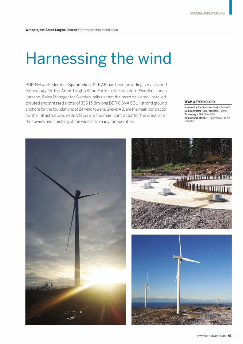
www.bbrnetwork.com 63
SPECIAL APPLICATIONS
TEAM & TECHNOLOGY
Main contractor (infrastructure) – Svevia AB
Main contractor (tower erection) – Vestas
Technology – BBR CONA SOL+
BBR Network Member – Spännteknik SLF AB (Sweden)
BBR Network Member Spännteknik SLF AB has been providing services and
technology for the Åmot-Lingbo Wind Farm in northeastern Sweden. Jonas
Larsson, Sales Manager for Sweden, tells us that the team delivered, installed,
grouted and stressed a total of 336 15.3m long BBR CONA SOL+ strand ground
anchors for the foundations of 24 wind towers. Svevia AB, are the main contractor
for the infrastructure, while Vestas are the main contractor for the erection of
the towers and finishing of the windmills ready for operation.
Windprojekt Åmot-Lingbo, Sweden Strand anchor installation
Harnessing the wind

Visualization of the completed Toru Apartments which are under construction using the seismically-resistant PRESSS system.
64 CONNÆCT | Edition 14
SPECIAL APPLICATIONS
The complex, named ‘Toru’ (the Maori name for
‘three’) has been designed by Mason + Wales
Architects to meet the burgeoning demand
for affordable housing in Queenstown. It will
comprise three seven-storey, campus-style
apartment buildings and offer 236 one-, two-
and three-bedroom apartments for sale and
rent, as well as communal lounges, commercial
spaces and on-site parking.
While the team at New Zealand’s BBR Contech often have the
opportunity to work in beautiful scenic surroundings, some of them
win work that has the others turning positively green with envy. This
is certainly the case with a project currently underway in the South
Island resort town of Queenstown, where BBR’s Christchurch team
is helping to build a new apartment complex with amazing views of
The Remarkables mountain range and beyond.
Toru Apartments, New Zealand Installation of seismically-resistant PRESSS technology
New apartments get the PRESSS treatment
TEAM & TECHNOLOGY
Owner – New Ground Living (Remarkables Park)
Structural engineer – Kirk Roberts Consulting
Project manager – Aecom New Zealand
Main contractor – Naylor Love Central
BBR Network Member – BBR Contech (New Zealand)
The buildings’ design has been driven by a
focus on prefabrication and modularization
to ensure both quality and cost-effective-
ness. Components such as wall and ceiling
panels and bathroom pods are prefabricated
off-site then assembled into completed
modules on-site, and in situ floors are poured
at each level as the structure progresses
upwards.
BBR Contech has been commissioned by
Naylor Love to install the post-tensioning for
the C-shaped, precast-concrete structural
walls that are positioned in sets of opposing
pairs to form the buildings’ core – enclosing
stairs, lifts and service areas at each end. The
walls are constructed using the PREcast Seis-
mic Structural System (PRESSS) technique,
in which unbonded post-tensioned, corro-
sion-protected tendons are installed through
precast concrete shear walls, then anchored at
foundation level and tensioned at the top. The
system provides seismic protection – enabling
a controlled rocking mechanism during an
earthquake that returns the building to upright
without significant structural damage.
In 1983, BBR Contech was the first in New
Zealand to use PRESSS for a multi-storey
building. This work, on Wellington’s Alan
MacDiarmid Building, went on to earn the
company a New Zealand Concrete Society
Concrete and Technology Award.
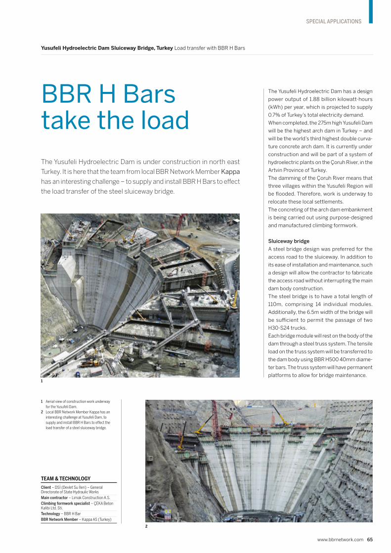
The Yusufeli Hydroelectric Dam has a design
power output of 1.88 billion kilowatt-hours
(kWh) per year, which is projected to supply
0.7% of Turkey’s total electricity demand.
When completed, the 275m high Yusufeli Dam
will be the highest arch dam in Turkey – and
will be the world’s third highest double curva-
ture concrete arch dam. It is currently under
construction and will be part of a system of
hydroelectric plants on the Çoruh River, in the
Artvin Province of Turkey.
The damming of the Çoruh River means that
three villages within the Yusufeli Region will
be flooded. Therefore, work is underway to
relocate these local settlements.
The concreting of the arch dam embankment
is being carried out using purpose-designed
and manufactured climbing formwork.
Sluiceway bridge
A steel bridge design was preferred for the
access road to the sluiceway. In addition to
its ease of installation and maintenance, such
a design will allow the contractor to fabricate
the access road without interrupting the main
dam body construction.
The steel bridge is to have a total length of
110m, comprising 14 individual modules.
Additionally, the 6.5m width of the bridge will
be sufficient to permit the passage of two
H30-S24 trucks.
Each bridge module will rest on the body of the
dam through a steel truss system. The tensile
load on the truss system will be transferred to
the dam body using BBR H500 40mm diame-
ter bars. The truss system will have permanent
platforms to allow for bridge maintenance.
The Yusufeli Hydroelectric Dam is under construction in north east
Turkey. It is here that the team from local BBR Network Member Kappa
has an interesting challenge – to supply and install BBR H Bars to effect
the load transfer of the steel sluiceway bridge.
Yusufeli Hydroelectric Dam Sluiceway Bridge, Turkey Load transfer with BBR H Bars
BBR H Bars take the load
1 Aerial view of construction work underway
for the Yusufeli Dam.
2 Local BBR Network Member Kappa has an
interesting challenge at Yusufeli Dam, to
supply and install BBR H Bars to effect the
load transfer of a steel sluiceway bridge.
www.bbrnetwork.com 65
SPECIAL APPLICATIONS
TEAM & TECHNOLOGY
Client – DSi (Devlet Su ileri) – General Directorate of State Hydraulic Works
Main contractor – Limak Construction A.S.
Climbing formwork specialist – ÇEKA Beton Kalibi Ltd. Sti.
Technology – BBR H Bar
BBR Network Member – Kappa AS (Turkey)
1
2

66 CONNÆCT | Edition 14
SPECIAL APPLICATIONS
Al Zour LNG Import Terminal, Kuwait Cryogenic post-tensioning of eight LNG tanks
Tanking up for LNG
1
The Al Zour Import Terminal Project, now well underway, includes the
construction of a large-scale liquefied natural gas (LNG) plant, including eight
LNG storage tanks, located 90km south of Kuwait. Rusper Patel from BBR
Network Member SRG Global describes his company’s work on the post-
tensioning of the eight LNG storage tanks which are a core part of the scheme.

www.bbrnetwork.com 67
SPECIAL APPLICATIONS
2
3
TEAM & TECHNOLOGY
Owner – Kuwait National Petroleum Company (KNPC)
Design & build contractor – Hyundai Engineering and Construction Co., Ltd
Technology – BBR VT CONA CMI internal
BBR Network Member – SRG Global (Middle East)
1 Night-time view across the site where eight
LNG tanks are under construction for the Al
Zour Import Terminal Project in Kuwait.
2 Aerial view of the site showing all eight LNG
tanks under construction at the same time.
3 For each of the eight tanks, the team from
SRG Global is installing 96m long vertical
loop tendons and 150m long horizontal
loop tendons.
Once fully operational, the facility is expected
to produce around 22 million metric tonnes
(MMT) of natural gas per year and will have
a storage capacity of 1.8 million cubic meters
of LNG.
Dimensions & technology
Each tank has a capacity of 225,500m3 with a
height of 47.65m, diameter of 97m and 750mm
wall thickness. SRG Global are using the
BBR VT CONA CMI internal post-tensioning
system which features tendons with 27 steel
strands of 15.2mm diameter – in total, the
project will use 10,000t of prestressing steel.
The installation includes 96m long vertical loop
tendons and 150m long horizontal loop ten-
dons. The BBR VT CONA CMI post-tensioning
system is fully certified for operations under
cryogenic conditions according to EAD16.
Certification testing for the CONA CMI
system included static and load transfer
testing of single and multistrand tendons
under full cryogenic conditions. The success-
ful test results verified the ductility and load
transfer performance of the CONA CMI system
with normal grade anti-bursting reinforcement
when subjected to extreme temperature
conditions (-196°C) and proved that it is in
full compliance with the EAD16 requirements,
for use in both temporary and permanent
cryogenic conditions, without any need
for costly low temperature grade rein-
forcement and thus delivering significant
material cost savings. For this project, the
design temperature for reinforcement steel
is -145°C and prestressing steel -85°C.
Progress in extreme heat
At the time of writing, SRG Global have com-
pleted approximately 40% of the stressing
works and are focused on completion of the
work by the end of 2020. The construction
regime is intense and requires the team to
push approximately 80t of strand each day.
Between 600 and 800 bags of cement are
used for grouting each day. The extreme
temperatures (40 to 50°C) mean that six
tonnes of ice are needed to maintain the grout
mix temperatures within specified tolerances.
In order to help maintain tolerances, most
work is done at night.
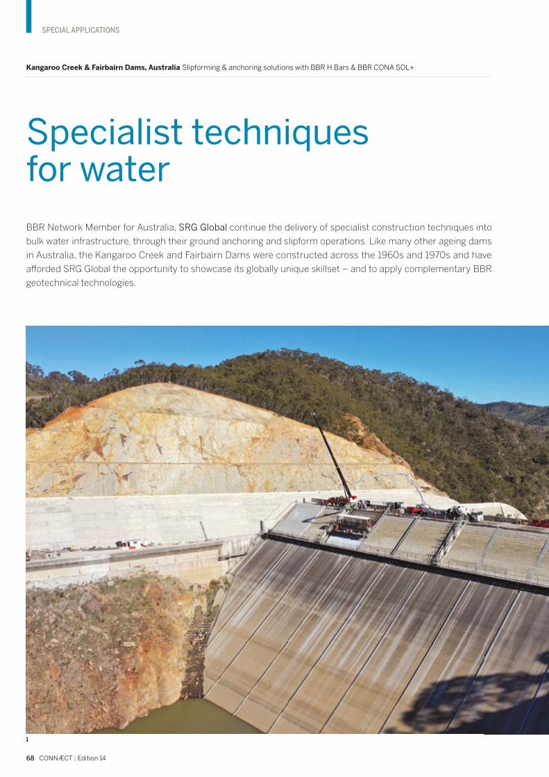
68 CONNÆCT | Edition 14
SPECIAL APPLICATIONS
BBR Network Member for Australia, SRG Global continue the delivery of specialist construction techniques into
bulk water infrastructure, through their ground anchoring and slipform operations. Like many other ageing dams
in Australia, the Kangaroo Creek and Fairbairn Dams were constructed across the 1960s and 1970s and have
afforded SRG Global the opportunity to showcase its globally unique skillset – and to apply complementary BBR
geotechnical technologies.
Kangaroo Creek & Fairbairn Dams, Australia Slipforming & anchoring solutions with BBR H Bars & BBR CONA SOL+
Specialist techniques for water
1

www.bbrnetwork.com 69
SPECIAL APPLICATIONS
1 Kangaroo Creek Dam
Slipforming work on dams has most com-
monly been used as a mechanism to apply
a reinforced concrete face to rockfill dams.
The slipform technique allows concrete to be
placed continuously on a grade, in approxi-
mately 12m wide panels. SRG Global’s works
on the Kangaroo Creek Dam Upgrade Project
in South Australia consisted of slipform con-
struction to two different areas of the dam.
Upstream embankment face slabs
The first was a total of 11 slipformed concrete
slabs on the upstream embankment face. The
embankment of the dam was being raised
which involved the following staging of works:
• Rockfill and filter materials were raised in
layers to the required height.
• Concrete kerbing was completed on the
upstream face in corresponding layers to
the rockfill and filter materials.
• Reinforcement was installed to the concrete
kerb face, where the concrete kerb acted
as a sacrificial foundation against which
the slipformed slabs were cast.
• Finally, the slipform slabs were cast.
The slipformed concrete slabs were cast on a
35 degree gradient in panels typically 12.2m
wide, 14m long at a slab thickness of 305mm.
The advance rate achieved was up to two
meters per hour.
Flip bucket slabs
The second area of slipform work involved
the construction of six slabs for the widened
flip bucket. As part of the upgrade, there was
a significant widening of the spillway chute
and flip bucket including relining the existing
concrete slabs.
The added complexity for the flip bucket was
that the gradient was variable, meaning that
the winching system and access platforms had
to cater for whether the slipform was operating
in an upwards or downwards state. Conven-
tional formwork techniques were considered,
such as fixed steel panels, however the high
quality achievable through adopting a slipform
approach was compelling.
The slipformed concrete slabs were cast on
gradients varying up to 42 degrees, typically
10m wide and 15m long. The thickness varied
significantly due to the nature of the founda-
tion excavated during the widening process,
however the minimum required was 400mm.
Slipform details
The slipform system comprises a counter-
weighted screed which incorporates a working
platform for concrete placement and external
vibrators. The counterweights ensure that the
screed does not float to a height above the
intended finished level of concrete. The screed
travels along temporary steel edge forms
and is progressively winched via two 15t SWL
electric man rider winches. These winches
were designed and built especially for this proj-
ect to cater for the line pull loads. In addition to
the slipform screed and its working platform,
there is a subsequent trailing deck which is
used to complete the concrete finishes and
apply the adopted curing technique. The
trailing deck can be set at a pre-determined
distance from the screed, based on the rate
of set of the concrete.
2 3

70 CONNÆCT | Edition 14
SPECIAL APPLICATIONS
5
1 Kangaroo Creek Dam – on the upstream
embankment face 11 slipformed concrete
slabs were constructed.
2 Kangaroo Creek Dam – slipforming
operations for the six slabs needed for the
widened flip bucket had to cope with the
added complexity of a varying gradient.
3 Kangaroo Creek Dam – the slipform system
comprises a counterweighted screed which
incorporates a working platform for
concrete placement and external vibrators.
4 Fairbairn Dam – installation of one of the
test anchors underway.
5 Fairbairn Dam – a total of 78 BBR CONA
SOL+ ground anchors, with 23 or 21 strands,
are now being drilled, fabricated and
installed for this project.
6 Fairbairn Dam – drilling and installation of
a series of test anchors was carried out to
prove the ultimate ground conditions and
enable optimization of the final post-
tensioned ground anchor design.
The ability to increase the capacity of ground anchors and reduce the number needed has meant that the program for the urgent works is shorter.
4
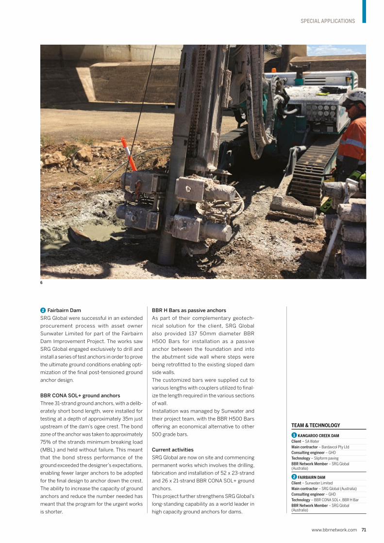
www.bbrnetwork.com 71
SPECIAL APPLICATIONS
TEAM & TECHNOLOGY
1 KANGAROO CREEK DAMClient – SA Water
Main contractor – Bardavcol Pty Ltd
Consulting engineer – GHD
Technology – Slipform paving
BBR Network Member – SRG Global (Australia)
2 FAIRBAIRN DAMClient – Sunwater Limited
Main contractor – SRG Global (Australia)
Consulting engineer – GHD
Technology – BBR CONA SOL+, BBR H Bar
BBR Network Member – SRG Global (Australia)
2 Fairbairn Dam
SRG Global were successful in an extended
procurement process with asset owner
Sunwater Limited for part of the Fairbairn
Dam Improvement Project. The works saw
SRG Global engaged exclusively to drill and
install a series of test anchors in order to prove
the ultimate ground conditions enabling opti-
mization of the final post-tensioned ground
anchor design.
BBR CONA SOL+ ground anchors
Three 31-strand ground anchors, with a delib-
erately short bond length, were installed for
testing at a depth of approximately 35m just
upstream of the dam’s ogee crest. The bond
zone of the anchor was taken to approximately
75% of the strands minimum breaking load
(MBL) and held without failure. This meant
that the bond stress performance of the
ground exceeded the designer’s expectations,
enabling fewer larger anchors to be adopted
for the final design to anchor down the crest.
The ability to increase the capacity of ground
anchors and reduce the number needed has
meant that the program for the urgent works
is shorter.
BBR H Bars as passive anchors
As part of their complementary geotech-
nical solution for the client, SRG Global
also provided 137 50mm diameter BBR
H500 Bars for installation as a passive
anchor between the foundation and into
the abutment side wall where steps were
being retrofitted to the existing sloped dam
side walls.
The customized bars were supplied cut to
various lengths with couplers utilized to final-
ize the length required in the various sections
of wall.
Installation was managed by Sunwater and
their project team, with the BBR H500 Bars
offering an economical alternative to other
500 grade bars.
Current activities
SRG Global are now on site and commencing
permanent works which involves the drilling,
fabrication and installation of 52 x 23-strand
and 26 x 21-strand BBR CONA SOL+ ground
anchors.
This project further strengthens SRG Global’s
long-standing capability as a world leader in
high capacity ground anchors for dams.
6

72 CONNÆCT | Edition 14
MRR
Two early 20th century bridges in New Zealand have recently received some
specialist attention from BBR Contech to ensure that they can continue to
serve their communities well into the future.
Tauweru & Waihenga Bridges, Wellington, New Zealand Increasing load capacity & repairs
New life for old bridges
As well as being similar in age, both bridges fea-
ture concrete piers and girders and both have
their feet in riverbeds. In addition, they’re only
about 50km apart in New Zealand’s Wairarapa
region which sits at the south-eastern corner of
the North Island. However, the similarities end
there, as the bridges have very different uses.
The 1922 Tauweru Bridge is 73.5m long and
services the farms and forests east of Mas-
terton, Wairarapa’s largest town. It carries the
greater load, often bearing massive trucks
taking heavy cargo to distant ports.
In sharp contrast, the 232m long, 22m span
Waihenga Bridge built in 1912 is part of a rural
state highway further south that is used by
much lighter vehicles. As well as carrying
local traffic, it often transports weekenders
and tourists visiting the popular vineyards of
Martinborough and the stores and cafés of
nearby Featherston and Greytown.
1

www.bbrnetwork.com 73
MRR
1 New Zealand’s 73.5m long Tauweru Bridge,
built in 1922, has received some specialist
strengthening and repairs.
2 The Tauweru project involved adding three
external, post-tensioned, greased and
sheathed tendons each side of the two
bridge beams.
3 Work at Waihenga Bridge included removing
spalled concrete by hydro-demolition,
installing a protective coating on the
reinforced steel and reinstating damaged
and broken concrete by dry-spraying.
Given their age and purpose, it is easy to under-
stand why BBR Contech spent a few months
in the region in 2019. The Tauweru Bridge
needed some strengthening to increase its
load capacity, while Waihenga, after many
years of service and a few problems with
flooding, needed structural repairs.
The Tauweru project had its challenges as it
had to remain open for the duration of the
work – heavy-duty ear protection was required
by those underneath! It involved adding
three external, post-tensioned, greased and
sheathed tendons each side of the two bridge
beams, plus carbon fiber reinforced polymer
(CFRP) reinforcement to the underside of the
deck. A discovery of extensive cracking in the
deck required some extra repairs which, while
unexpected, will make a significant contribu-
tion to the bridge’s long-term well-being.
As for the Waihenga Bridge, it emerged in
much better shape after the BBR Contech
team had removed spalled concrete with
help from hydro-demolition experts, installed
a protective coating on the reinforced steel
and reinstated damaged and broken concrete
using a dry-spray method. All the excavated
material was collected, removed and disposed
of off-site, reflecting BBR Contech’s stan-
dard practice and complying with the local
council-issued resource consent conditions.2
3
TEAM & TECHNOLOGY
1 TAUWERU BRIDGEOwner – Masterton District Council
Main Contractor – BBR Contech
Designer – WSP
Technology – BBR VT CONA CME external, MRR range
BBR Network Member – BBR Contech (New Zealand)
2 WAIHENGA BRIDGEOwner – NZ Transport Agency
Main Contractor – BBR Contech
Designer – WSP
Technology – MRR range
BBR Network Member – BBR Contech (New Zealand)
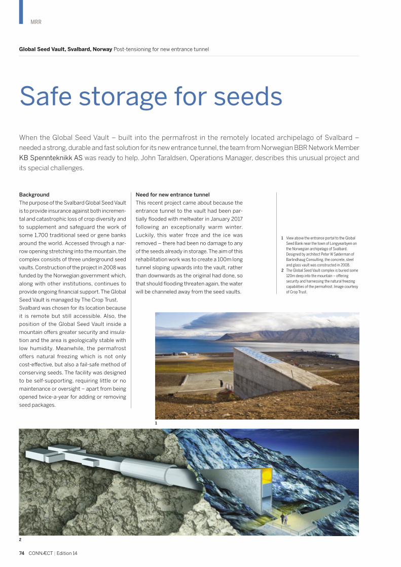
74 CONNÆCT | Edition 14
MRR
Background
The purpose of the Svalbard Global Seed Vault
is to provide insurance against both incremen-
tal and catastrophic loss of crop diversity and
to supplement and safeguard the work of
some 1,700 traditional seed or gene banks
around the world. Accessed through a nar-
row opening stretching into the mountain, the
complex consists of three underground seed
vaults. Construction of the project in 2008 was
funded by the Norwegian government which,
along with other institutions, continues to
provide ongoing financial support. The Global
Seed Vault is managed by The Crop Trust.
Svalbard was chosen for its location because
it is remote but still accessible. Also, the
position of the Global Seed Vault inside a
mountain offers greater security and insula-
tion and the area is geologically stable with
low humidity. Meanwhile, the permafrost
offers natural freezing which is not only
cost-effective, but also a fail-safe method of
conserving seeds. The facility was designed
to be self-supporting, requiring little or no
maintenance or oversight – apart from being
opened twice-a-year for adding or removing
seed packages.
Need for new entrance tunnel
This recent project came about because the
entrance tunnel to the vault had been par-
tially flooded with meltwater in January 2017
following an exceptionally warm winter.
Luckily, this water froze and the ice was
removed – there had been no damage to any
of the seeds already in storage. The aim of this
rehabilitation work was to create a 100m long
tunnel sloping upwards into the vault, rather
than downwards as the original had done, so
that should flooding threaten again, the water
will be channeled away from the seed vaults.
2
1 View above the entrance portal to the Global
Seed Bank near the town of Longyearbyen on
the Norwegian archipelago of Svalbard.
Designed by architect Peter W Søderman of
Barlindhaug Consulting, the concrete, steel
and glass vault was constructed in 2008.
2 The Global Seed Vault complex is buried some
120m deep into the mountain – offering
security and harnessing the natural freezing
capabilities of the permafrost. Image courtesy
of Crop Trust.
Global Seed Vault, Svalbard, Norway Post-tensioning for new entrance tunnel
Safe storage for seeds
1
When the Global Seed Vault – built into the permafrost in the remotely located archipelago of Svalbard –
needed a strong, durable and fast solution for its new entrance tunnel, the team from Norwegian BBR Network Member
KB Spennteknikk AS was ready to help. John Taraldsen, Operations Manager, describes this unusual project and
its special challenges.
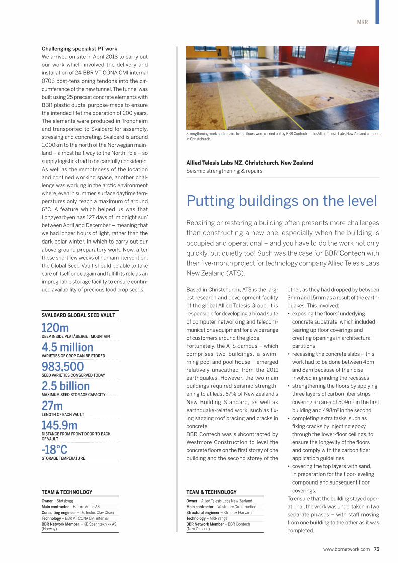
Based in Christchurch, ATS is the larg-
est research and development facility
of the global Allied Telesis Group. It is
responsible for developing a broad suite
of computer networking and telecom-
munications equipment for a wide range
of customers around the globe.
Fortunately, the ATS campus – which
comprises two buildings, a swim-
ming pool and pool house – emerged
relatively unscathed from the 2011
earthquakes. However, the two main
buildings required seismic strength-
ening to at least 67% of New Zealand’s
New Building Standard, as well as
earthquake-related work, such as fix-
ing sagging roof bracing and cracks in
concrete.
BBR Contech was subcontracted by
Westmore Construction to level the
concrete floors on the first storey of one
building and the second storey of the
other, as they had dropped by between
3mm and 15mm as a result of the earth-
quakes. This involved:
• exposing the floors’ underlying
concrete substrate, which included
tearing up floor coverings and
creating openings in architectural
partitions
• recessing the concrete slabs – this
work had to be done between 4pm
and 8am because of the noise
involved in grinding the recesses
• strengthening the floors by applying
three layers of carbon fiber strips –
covering an area of 509m2 in the first
building and 498m2 in the second
• completing extra tasks, such as
fixing cracks by injecting epoxy
through the lower-floor ceilings, to
ensure the longevity of the floors
and comply with the carbon fiber
application guidelines
• covering the top layers with sand,
in preparation for the floor-leveling
compound and subsequent floor
coverings.
To ensure that the building stayed oper-
ational, the work was undertaken in two
separate phases – with staff moving
from one building to the other as it was
completed.
Repairing or restoring a building often presents more challenges
than constructing a new one, especially when the building is
occupied and operational – and you have to do the work not only
quickly, but quietly too! Such was the case for BBR Contech with
their five-month project for technology company Allied Telesis Labs
New Zealand (ATS).
Allied Telesis Labs NZ, Christchurch, New Zealand
Seismic strengthening & repairs
Putting buildings on the level
www.bbrnetwork.com 75
MRR
Strengthening work and repairs to the floors were carried out by BBR Contech at the Allied Telesis Labs New Zealand campus
in Christchurch.
TEAM & TECHNOLOGY
Owner – Allied Telesis Labs New Zealand
Main contractor – Westmore Construction
Structural engineer – Structex Harvard
Technology – MRR range
BBR Network Member – BBR Contech (New Zealand)
Challenging specialist PT work
We arrived on site in April 2018 to carry out
our work which involved the delivery and
installation of 24 BBR VT CONA CMI internal
0706 post-tensioning tendons into the cir-
cumference of the new tunnel. The tunnel was
built using 25 precast concrete elements with
BBR plastic ducts, purpose-made to ensure
the intended lifetime operation of 200 years.
The elements were produced in Trondheim
and transported to Svalbard for assembly,
stressing and concreting. Svalbard is around
1,000km to the north of the Norwegian main-
land – almost half-way to the North Pole – so
supply logistics had to be carefully considered.
As well as the remoteness of the location
and confined working space, another chal-
lenge was working in the arctic environment
where, even in summer, surface daytime tem-
peratures only reach a maximum of around
6°C. A feature which helped us was that
Longyearbyen has 127 days of ‘midnight sun’
between April and December – meaning that
we had longer hours of light, rather than the
dark polar winter, in which to carry out our
above-ground preparatory work. Now, after
these short few weeks of human intervention,
the Global Seed Vault should be able to take
care of itself once again and fulfill its role as an
impregnable storage facility to ensure contin-
ued availability of precious food crop seeds.
SVALBARD GLOBAL SEED VAULT
120mDEEP INSIDE PLATÅBERGET MOUNTAIN
4.5 millionVARIETIES OF CROP CAN BE STORED
983,500SEED VARIETIES CONSERVED TODAY
2.5 billionMAXIMUM SEED STORAGE CAPACITY
27m LENGTH OF EACH VAULT
145.9mDISTANCE FROM FRONT DOOR TO BACK OF VAULT
-18°CSTORAGE TEMPERATURE
TEAM & TECHNOLOGY
Owner – Statsbygg
Main contractor – Hæhre Arctic AS
Consulting engineer – Dr. Techn. Olav Olsen
Technology – BBR VT CONA CMI internal
BBR Network Member – KB Spennteknikk AS (Norway)

76 CONNÆCT | Edition 14
MRR
Viaduc d’Echinghen, Autoroute A16, Saint-Léonard, France
External PT using BBR VT CONA CME BT with monostrands
Renewed strength for vital infrastructure
The ultimate flexibility of BBR technology – as well as the innovation of the
BBR Network – is demonstrated very clearly in projects which breathe new
life into structures. One such example is the repair of a viaduct in Northern
France, where French BBR Network Member, ETIC has recently had a
further opportunity to showcase their expertise in installing external post-
tensioning. Project Managers Victor Barray and Antoine Dupré report on the
work their company is undertaking and the challenges of working in such an
exposed location.
The Echinghen Viaduct was built in 1996,
near the town of Saint-Léonard, close to
Boulogne-sur-Mer in the Pas-de-Calais region
of Northern France. It is part of the A16 motor-
way which runs along the French coast from
the Channel ports – in a southerly direction
to Amiens and the Paris area and northwards
to the Belgian border. The Echinghen Viaduct
and two other motorway bridges are together
known locally as the ‘Boulonnais Viaducts’ or
simply ‘Le Boulonnais’. Today, this part of the
A16 motorway is a toll road which is managed
and maintained by Société des Autoroutes du
Nord et de l'Est de la France (SANEF).
The 1,301m long Echinghen Viaduct is a post-
tensioned concrete box girder construction
with a main span of 110m and standing, at
its tallest, 70m above the landscape. In 2017,
during routine inspections, the viaduct was
showing signs of ageing, thus after imposing
speed limits and heavy vehicle restrictions,
the operator SANEF commissioned renova-
tion work.
Unique repair challenge
The team from ETIC is replacing 11 external
post-tensioning tendons. The project is unique
as it consists of replacing 19T15 bare strands
with 15T15 BBR VT CONA CME BT tendons
with monostrands. The strands need to be
fitted within a 110mm diameter HDPE duct
which means that the duct will be filled to
around 60% of capacity – that alone is a
tricky job!
1

www.bbrnetwork.com 77
MRR

78 CONNÆCT | Edition 14
MRR
Special component design
In addition, as some of the tendons need to be
replaced after only 23 years’ service, the client
wanted a system with easily exchangeable ten-
dons should the same defects arise again after
a just few decades. However, the viaduct was
built using a non-BBR post-tensioning system.
This meant that the ETIC team had to find a
way of adapting the new BBR VT CONA CME
post-tensioning to the existing system.
To achieve this, ETIC designed a special
component they called ‘the lantern’ – basically,
this is a thick steel element screwed onto the
old trumplate on one side and which holds
the double layer of CONA CME post-tension-
ing on the other side. The idea is to use the
old anchorages to install the new BBR anchor-
ages, thereby avoiding the need to cast any
concrete sections for installation of a complete
BBR anchorage.
The project presented many challenges. For
example, it was impossible to use the basic
pushing method for strand installation since
there was so little space in the duct. The
solution was to pull all the 15 strands together
into a bunch and then, using a winch, all the
strands were pulled inside the duct.
Outlook & future challenges
As CONNÆCT 2020 goes to press, ETIC will
be putting the final touches to their work –
completion was carefully scheduled before
winter really hits this region where climatic
conditions would be very tough for the
people working in such an exposed location.
At the end of the external post-tensioning
work, the motorway will be fully reopened to
road traffic.
This project – along with our work on the two
viaducts for the A9 motorway as reported
in the last edition of CONNÆCT – will be an
important reference for ETIC in the future,
as there will be many projects like this in the
coming years. In France, as in much of west-
ern Europe and indeed North America, most
infrastructure has been in place for many years
– and, as this project illustrates, the challenge
now is now to maintain these important struc-
tures using the best and latest technology and
techniques to ensure their continued service.
1 A vital infrastructure element, the Viaduct
d’Echinghen in the Pas-de-Calais region of
France, has been strengthened with BBR VT
CONA CME BT external post-tensioning and
given a new lease of life.
2 The program for strengthening work on the
viaduct was carefully scheduled to avoid
exposing the workforce to the harsh local
winter conditions.
TEAM & TECHNOLOGY
Client – SANEF
Main contractor – ETIC SAS (France)
Technology – BBR VT CONA CME external
BBR Network Member – ETIC SAS (France)
2

www.bbrnetwork.com 79
MRR
In March 2021, Auckland will host the 36th
America’s Cup which, having been recognized
for almost 170 years as the world’s premium
yachting event, is the oldest trophy in interna-
tional sport. About 26,000 international and
175,000 domestic visitors are expected to
travel to Auckland to watch Team New Zealand
defend its title on the Waitemata Harbour, with
the event likely to generate up to NZ$1 billion
in value for New Zealand’s economy.
Later in the year, Auckland will provide the
venue for the APEC 2021 Leaders’ Week – the
culmination of a year-long event that will be the
largest ever hosted by the New Zealand Gov-
ernment. An estimated 10,000 attendees are
expected to be in the city for Leaders’ Week,
including world leaders, trade and foreign minis-
ters, business leaders and international media.
In preparation for these events, Auckland’s
waterfront and lower downtown area are
being given a NZ$2 billion facelift – the big-
gest concentrated urban transformation ever
undertaken in New Zealand. The aim is to pro-
vide the infrastructure for the America’s Cup,
an outstanding destination for visitors and a
long-term legacy for the people of New Zealand.
BBR Contech has been involved in repair-
ing and upgrading Auckland’s wharves and
ferry terminals for more than 25 years. The
company returned to the waterfront for this
project in 2018 (see CONNÆCT 2019) which
has included works at Wynyard Wharf, where
four of the America’s Cup challenger syndi-
cates will be based.
More recently, the team undertook a package
of repairs to upgrade a portion of the Down-
town Ferry Terminal – the hub of an extensive
ferry network that connects Auckland city
to surrounding suburbs and islands in the
Waitemata Harbour and Hauraki Gulf. The first
of a number of projects that will upgrade the
infrastructure in the area, the repairs have
involved hydrodemolition, reinforcing steel
repair and replacement, plus reinstatement
through a combination of box-and-pour-and-
spray-concrete techniques.
The challenges have been many – including
the tides and the need to work around the
ferry passengers and timetables. But with the
likely increased use of the facility in 2021,
it’s work that’s well worth doing – the trans-
formation will not only boost Auckland’s
reputation on the world stage, but also help
to create a truly international city for today’s
and future generations.
Two major events scheduled for 2021 have driven a long-term
wharf repair and strengthening project in Auckland, New Zealand –
the America’s Cup and the APEC 2021 Leaders’ Week.
Downtown wharfs, Auckland, New Zealand Repairs & strengthening work
Supporting a downtown transformation
TEAM & TECHNOLOGY
Client – Downtown Joint Venture
Main contractor – BBR Contech
Structural engineer – Beca
Technology – MRR range
BBR Network Member – BBR Contech (New Zealand)
1 The Downtown Ferry Terminal in Auckland,
New Zealand where BBR Contech have carried
out repairs and strengthening work.
2 Repairs at the Downtown Ferry Terminal site
included bracing to the underside of the wharf.
1 2

80 CONNÆCT | Edition 14
TECHNOLOGY
The BBR VT CONA CMG strand ground anchor
system offers state-of-the-art performance,
including a wide size range across three
different corrosion protection levels to
allow customers to select the optimum force
range and design life characteristics for
specific projects. Designed for geotechni-
cal applications, as soil or rock anchors, the
system covers a maximum force range which
aims to satisfy the major market demands.
The BBR VT CONA CMG anchor is an optim-
ized system which has been designed to ensure
both effective performance and economy.
Our team has not only created a new bench-
mark in corrosion protection for ground
anchors, but has also devised for the first time
a method for measurement of grout crack-
ing of a confined and stressed anchor under
service load.
Main components & performance
The main components of the BBR VT CONA
CMG system are:
• the anchorage & transition zone –
including corrosion protection elements
and a solution to lock-in the load bearing
tendon elements
• the tendon in the free length – where
the strands are unbonded, allowing free
elongation
• the tendon in the bond length – where
the strands are bonded to the surrounding
ground by means of cementitious grout.
The BBR VT CONA CMG system is the very latest construction engineering
technology which has been introduced to the international market with
impeccable Swiss credentials – and proven high levels of corrosion protection.
Dr. Ing. Xiaomeng Wang, BBR VT International’s Senior R&D Engineer
Geotechnical Systems, shares some details of this latest geotechnical system
and the innovative and thorough testing process adopted.
New international benchmark in GT technology
Research & Development BBR VT CONA CMG system – Geotechnical strand ground anchors
1

Centralizer
Steel strap
Steel strap
Protection cap
Transition pipe kit
Recess pipe
Sealing
Sheathed monostra
nd
in free length
Bare strand in bond length
Corrugated duct
Inner cement
grout
Spacer
Sealing
sleeve
End cap
Cord
Grouting pipe
Sealing at the
end of sheath
Corrosion
protection
compound
Anchor head
Bearing plate
2
www.bbrnetwork.com 81
TECHNOLOGY
Three solution kits
The BBR VT CONA CMG system provides three
solution kits with different corrosion protection
levels, designed for applications with different
service lives – up to two years, extended use up
to seven years and over seven years:
• Economical short-term ground anchor
The BBR VT CONA CMG short-term
solution is a temporary strand ground
anchor for applications of up to two years
and represents an economical solution.
Key components are protected by a
primary corrosion protection layer to
guarantee the effective anchor
performance through the limited duration
of an application.
• Temporary ground anchor
The BBR VT CONA CMG solution for
temporary anchors is for applications
requiring extended use of up to seven
years. It offers at least one continuous
corrosion protection layer around the
periphery of the anchor. This solution is
typically used to temporarily secure
excavations as tie-backs on construction
projects of longer duration.
• Highest durability permanent ground
anchor
The BBR VT CONA CMG permanent
solution exhibits the highest corrosion
protection level for a ground anchor of
this type. It provides two complete
corrosion protection layers, which form
continuous barriers around the key steel
components of the anchor.
The fully tested and approved set-up of a
BBR VT CONA CMG system ensures
effective double corrosion protection
through the corrugated duct and grout.
Any potential cracking under service load
is limited to a maximum of 0.1mm, as
proven by testing and thus the grout is
accepted as a corrosion protection layer.
The BBR VT CONA CMG permanent
solution is used for strand ground anchors
which have a design life of over seven
years as tie-back anchors, uplift control,
slope stabilization or rockfall protection.
Bearing plate
Grouting pipe
er
Centralizer
thed monostra
nd
th
d length
Bare strand in bond le
Inner cement
grout
Spacer
Sealing
sleeve
apBearing plate
Grouting pipeProtectio
n cap
Anchor head Recess pipe
(optional)
Sheathed monostra
nd
in free length
Transition
pipe kit
Sealing at the end
of sheath
Bare strand in
bond length
Spacer
Centralizer
Steel strap
Corrosion
protection
compound
Solutions with BBR VT CONA CMG
Top: Economical short-term ground anchor
Middle: Temporary ground anchor
Bottom: Permanent ground anchor
BBR VT CONA CMG system: key benefits
• Latest technology – engineered in response to recent market feedback
mitigates drawbacks of existing solutions.
• Unique-in-the-market corrosion protection features – enhanced corrosion
protection in transfer zone underneath the bearing plate and leak-tightness
of the PE-sheathed strand, which meets the criteria of latest European
Assessment Documents (EADs).
• Effective double corrosion protection solution – due to proven crack
limitation of grout.
• Widest range of anchorage sizes – allows use of right size anchorage for
each project, without needing to use oversized solutions.
Transition pipe kit
Bearing plate
Sealing at the end
of sheath
Sheathed monostra
nd
in free length
Bare strand in
bond length
Spacer
Centralizer
Steel strap
Grouting pipe
Anchor
head

82 CONNÆCT | Edition 14
TECHNOLOGY
New benchmark for corrosion protection
Corrosion protection of a ground anchor
is crucial to achieving the desired perfor-
mance, as the strand ground anchors are
typically installed in ground conditions
which vary in terms of density, porosity,
water level and environmental aggres-
sivity – and monitoring is impossible as
the installed anchor effectively becomes
invisible.
Since the 1980s, more-and-more attention
has been drawn to the corrosion of strand
anchors. A study from the fib working
group on ground anchorages revealed that,
among 42 failure incidents examined due
to tendon corrosion, most of them occurred
at the anchorage or transition zone
(19 incidents) and in the free length
(21 incidents), while only two incidents
occurred in the bond length. The high risk
of corrosion on the anchorage, transition
zone and the free length has been con-
firmed by other recent studies such as
those by Mothersille (Australia, 2011) and
Liao (Taiwan, 2018).
The outcome of the studies on historical
cases have been addressed within the
BBR VT CONA CMG system which takes
corrosion protection to a whole new level.
Alongside common, robust corrosion
protection methods, this system intro-
duces a set of performance-enhancing
measures which are totally new to the mar-
ket. With these new corrosion features, the
CONA CMG system has set a new global
benchmark in the development of con-
struction technology.
• Transition zone sealing
It is now well-known that the transition
zone beneath the anchorage zone bears
the highest risk of corrosion. The PE
sheath of the free length of monostrand
ends in this zone and thus the bare surface
of the strands can be exposed. Unlike
many unsecured filling solutions applied
in the market, the BBR VT CONA CMG
system provides a fully sealed transition
pipe kit for each individual monostrand.
The transition pipe is sealed against water
ingress up to 3.5 bars at the two ends.
The space within the transition tube is
filled with corrosion-inhibiting compound
(optional for short-term solution).This
solution minimizes the risk of full tendon
failure as the bare strand protruding
beyond the PE sheath is fully encapsulated
by the transition tube and flexible
anti-corrosion compound. Should one
strand somehow become exposed to
corrosion, all the other strands are still fully
protected and isolated from the corrosion
source. While maximizing corrosion
protection, this unique solution can also
minimize workload as the transition pipe
kit is pre-assembled in the factory. The
seal between the recess pipe and
corrugated duct is yet another key feature
of BBR’s system. The solution is designed
for BBR VT CONA CMG permanent
anchors and tested accordingly.
• Monostrand in free length
In a ground anchor, the free length of
the tendon is unbonded from grout so
as to transfer tensile force from the
bond length to the anchorage. Lack of
proper protection of the tensile element
in the free length from alkaline
cementitious grout exposes it to possible
corrosion, such is often the case in
existing solutions. In a monostrand, the
free length of the strand is covered by a
flexible and durable PE sheath and the
cavity between the strands and PE sheath
is filled with anti-corrosion compound.
The monostrand is designed to be
leak-tight (according to EAD 16) and the
joint position between the free length and
bond length is fully sealed up to 3.5 bar to
avoid water or cementitious grout ingress.
• Proven bond length protection
The BBR VT CONA CMG system is the
very first strand anchor system in which
the cementitious grout in the single layer
corrugated duct has been designed and
proven by testing to be an effective
protection barrier against corrosion
according to EN1537. This certified
double-layer protection solution for BBR
VT CONA CMG permanent anchors
delivers a significant economic advantage
when compared with other solutions on
the market which typically feature two
layers of corrugated ducting – requiring
larger boreholes, bigger drilling equipment,
more materials and other resources which
mean additional costs– to achieve the
same international standard requirements
for corrosion protection.
Protection cap
Anchor head
Transition pipe kit
Recess pipe
Corrosion protection
compound in
transitio
n pipe
Corrugated duct
Sealing ring in the protectio
n cap
Bearing plate
Sealing ring
PE sheathed
monostrand
Wedge
Corrosion protection
compound in
protection cap
Cap for
injection port
3

www.bbrnetwork.com 83
TECHNOLOGY
This ETA covers both the CONA CMF S1 system
and the advanced next generation CONA CMF
S2 system which offers the widest anchorage
and coupler size range and the thinnest pos-
sible slab depths on the international market.
Furthermore, the CONA CMF S2 system
requires only one type of anti-bursting
reinforcement – either helix or stirrup – and
features the lowest reinforcement require-
ment of any system currently available.
The optimized design of the CONA CMF S2
system also achieves the smallest minimum
center spacing and slab thickness at low
concrete strength for all sizes on the market.
The CONA CMF S2 system can be integrated
with the CONA CMO system (ETA-15/0808)
as the fixed anchorage, contributing to
increased efficiency in terms of installation,
a reduction in labor requirements and mate-
rials consumption.
The European Technical Assessment (ETA-12/0076) has been renewed for
BBR VT CONA CMF post-tensioning technology and is available on the BBR
Network website for download.
Technical Update Renewal of ETA for BBR VT CONA CMF
European Assessment renewed for CONA CMF
1 The BBR VT CONA CMG strand ground anchor
is an optimized system which ensures both
effective performance and economy while
setting a new bench mark in corrosion
protection. Pictured here, ground anchors are
being installed for a wind tower at the Årjäng
& Tanum Wind Park in Norway.
2 (Top) The BBR VT CONA CMG short-term
economical strand ground anchor solution.
(Middle) The BBR VT CONA CMG temporary
strand ground anchor solution.
(Bottom) The BBR VT CONA CMG permanent
solution – providing highest durability strand
ground anchors.
3 Bare strand in the transition zone is fully
encapsulated by a transition pipe and flexible
anti-corrosion compound.
4 Advanced corrosion protection test B – with
crack width assessment method.
4
Testing provisions for mechanical
& corrosion protection performance
While testing and approval verifies that the
BBR VT CONA CMG system meets all the
requirements of EN1537, we apply the same
strict approach to quality and performance
to all of our technologies. The mechanical per-
formance of the BBR VT CONA CMG system
has been assessed, tested and proven as a
member of the BBR VT CONA CMX system
family range according to the latest European
Assessment Document EAD 160004-00-0301
following all the testing provisions – static,
fatigue and load transfer tests.
Assessment & verification of constancy
of performance
The CONA CMG system has been assessed
and proven in the same way as BBR ETA
approved post-tensioning systems with the
objective of establishing the CE mark for this
product in the near future.
After the strict initial assessment of the sys-
tem, the constancy of performance is ensured
by yearly audit of component manufacturers as
well as BBR Factory Production Control (FPC)
which includes continuous surveillance and full
traceability, as well as Pre-Delivery Inspection
(PDI) before every order is dispatched.
... the CONA CMG system has set a new global benchmark in the development of con struction technology.
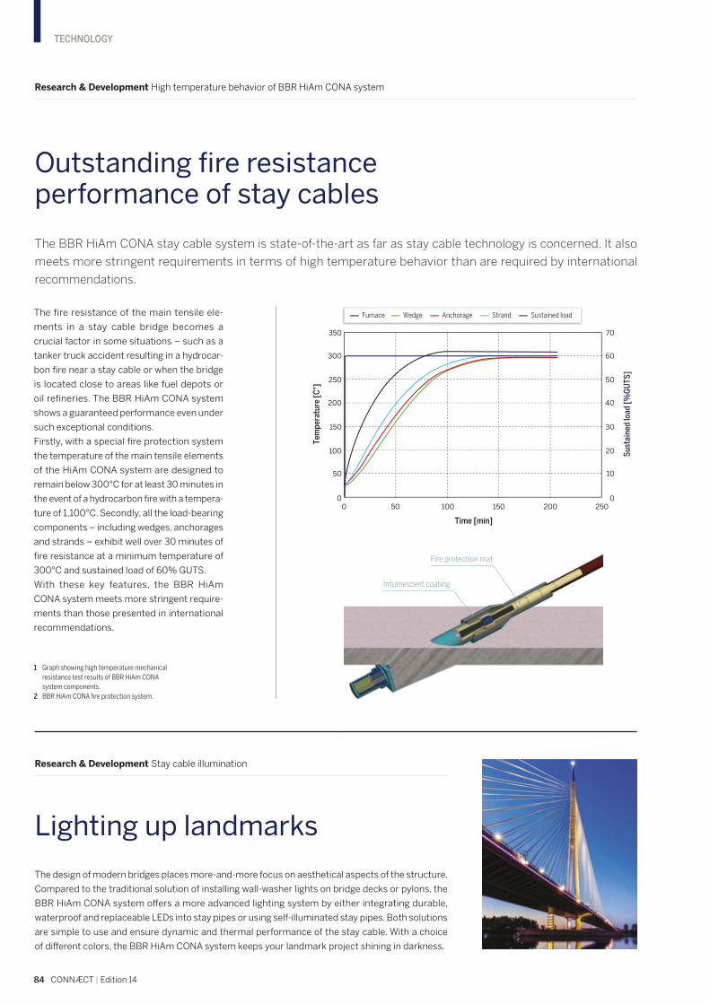
84 CONNÆCT | Edition 14
TECHNOLOGY
Outstanding fire resistance performance of stay cables
Research & Development High temperature behavior of BBR HiAm CONA system
The BBR HiAm CONA stay cable system is state-of-the-art as far as stay cable technology is concerned. It also
meets more stringent requirements in terms of high temperature behavior than are required by international
recommendations.
The fire resistance of the main tensile ele-
ments in a stay cable bridge becomes a
crucial factor in some situations – such as a
tanker truck accident resulting in a hydrocar-
bon fire near a stay cable or when the bridge
is located close to areas like fuel depots or
oil refineries. The BBR HiAm CONA system
shows a guaranteed performance even under
such exceptional conditions.
Firstly, with a special fire protection system
the temperature of the main tensile elements
of the HiAm CONA system are designed to
remain below 300°C for at least 30 minutes in
the event of a hydrocarbon fire with a tempera-
ture of 1,100°C. Secondly, all the load-bearing
components – including wedges, anchorages
and strands – exhibit well over 30 minutes of
fire resistance at a minimum temperature of
300°C and sustained load of 60% GUTS.
With these key features, the BBR HiAm
CONA system meets more stringent require-
ments than those presented in international
recommendations.
1 Graph showing high temperature mechanical
resistance test results of BBR HiAm CONA
system components.
2 BBR HiAm CONA fire protection system.
The design of modern bridges places more-and-more focus on aesthetical aspects of the structure.
Compared to the traditional solution of installing wall-washer lights on bridge decks or pylons, the
BBR HiAm CONA system offers a more advanced lighting system by either integrating durable,
waterproof and replaceable LEDs into stay pipes or using self-illuminated stay pipes. Both solutions
are simple to use and ensure dynamic and thermal performance of the stay cable. With a choice
of different colors, the BBR HiAm CONA system keeps your landmark project shining in darkness.
Research & Development Stay cable illumination
Lighting up landmarks
0 50 100 150 200 2500
50
100
150
200
300
250
350
Tem
pera
ture
[C°]
0
10
20
30
40
60
50
70
Sust
aine
d lo
ad [%
GU
TS]
Time [min]
Furnace Wedge Anchorage Strand Sustained load
Intumescent coating
Fire protection mat

www.bbrnetwork.com 85
TECHNOLOGY
Over
650,000tmaterials saved
Automating the construction process
Techniques Working with MSS Technologies
One of the hottest topics in the construction industry is productivity – and how
to increase it. Without doubt, the use of smarter technologies and techniques
plays a major role in speeding up the process. Efe Bayram from Turkey-based
BBR Network Member, Kappa shares an insight into the massive time and
materials savings his company has delivered for customers through the use
of Movable Scaffolding Systems.
1

86 CONNÆCT | Edition 14
TECHNOLOGY
The Movable Scaffolding Systems (MSS) can
be used in the span-by-span deck construc-
tion of viaducts and bridges. This technology
can reduce self-weight in viaducts and bridges
thereby cutting material usage by 40%. Auto-
mating the construction process cuts-down
time allocated to non-value adding activities
and eliminates the need for additional labor.
Enhanced safety & unprecedented spans
In addition to the time and material advantages
it provides, the MSS can reduce operational
risks and provide safer working conditions rel-
ative to traditional scaffolding systems.
We currently possess two systems – an MSS-
55 and MSS-90 designed and manufactured
by BERD – which are used for maximum spans
of 55m and 90m respectively. The usage of
MSS for a span of 90m is unprecedented –
previously the largest bridge span constructed
using MSS technology was 70m.
Recently, we have deployed our MSS tech-
nology for the Kayas-Yerköy high speed
railway viaduct project. The project consists
of four individual viaducts with a total length
of over 6km. The customer had originally
planned to use traditional balanced cantilever
construction methodology for the viaducts.
On learning that we could provide them with
huge savings on labor and material usage, they
adapted their plan to take advantage of our
MSS capability.
MSS overview
The MSS-90 spans 152m from front-nose to
rear-nose. It has a height of 20m and a width of
18m. Structurally, it makes use of a ‘bowstring’
type truss to overcome stresses associated
with the large span size.
Overhead crane system & locomotion
The overhead crane system is powered by two
winches located on the MSS. The movement
of free supports through the overhead crane
system allows the MSS to perform pier-to-
pier locomotion. Additionally, bridge deck
reinforcement can be pre-assembled and
brought to the work front using the same
winches. This provides a tremendous time
advantage over manual on-site assembly.
The construction of each 90m span takes
an average time of 13 days. Each deck span
makes use of 70t of prestressing steel. This
duration is much shorter when compared to
other methodologies used for performing the
same operation.
1 One of Kappa’s Movable Scaffolding Systems
(MSS) which significantly reduce the time
needed to construct a bridge span.
2 The MSS in action on the Kayas-Yerköy high
speed railway viaduct project.
3 Shown here illuminated at night, the MSS-90
spans 152m from front-nose to rear-nose and
makes use of a ‘bowstring’ type truss to
overcome stresses associated with the large
span size.
2
The usage of MSS for a span of 90m is unprecedented – previously the largest bridge span constructed using MSS technology was 70m.

www.bbrnetwork.com 87
TECHNOLOGY
Step 1: The MSS is brought to its
initial concrete pouring position after
pier-to-pier movement. The exterior
concrete forms are closed.
Step 2: Pre-manufactured steel
reinforcement fitted with PT tendon
ducts is brought on-site using the
overhead crane.
Step 3: Interior formwork is
assembled and phase one (web)
concrete is poured.
Step 4: Scaffolding for the concrete
deck is installed. Deck reinforcement
fitted with PT tendon ducts is
brought on-site. Phase two (deck)
concrete is poured.
Step 5: Once the deck concrete is
cured, the PT tendons in the wall are
stressed. After stressing, the concrete
loads can be transferred from the MSS
to the bridge deck itself.
Step-by-Step Guide
Organic Prestressing System
The MSS-90 makes use of an Organic Pre-
stressing System (OPS) named after its
biomimetic design. The OPS adaptively
reduces deformations in a structure caused
by varying live loads. In the case of the MSS-
90, the PT tendon stresses are adjusted as
concrete loads are added. The mid-span
deflection is measured by means of pressure
transducers located on the truss structure.
When the transducers detect that mid-span
deflection is greater than the pre-defined
limit, the hydraulic cylinder stroke length is
automatically adjusted to increase tension in
the tendons.
Electrically powered concrete forms
The concrete forms used for the deck are
electrically powered. This allows for shorter
concrete pouring durations and greater
reliability relative to hydraulically powered
alternatives.
Eliminating dependency on
geographical conditions
Ultimately, the MSS can eliminate depen-
dency on geographical conditions. Additional
spending on improving site conditions – such
as creating access roads and improving ground
conditions for scaffolding – can be greatly
reduced. The advantages offered by the all-
round performance of the latest MSS systems
are compelling and will continue to deliver out-
standing results for our customers.
Efficiency-oriented design for a green future
Through efficiency-oriented design, the MSS
has reduced material usage by more than
50,000 trucks-worth of concrete and 45,000t
of steel. This amounts to a 28,000t reduction
in carbon dioxide emissions. Considering that
cement production has been estimated to
represent a massive 8% of all global carbon
emissions annually, MSS technology is exem-
plary in its ability to considerably scale-down
the carbon footprint associated with such
projects for transportation infrastructure.
3
Kayas-Yerköy High Speed Rail Viaduct Project
Viaduct No Width (m) Length (m) PT tendons (tons)
7 13.2 1,800 1,246
9 13.2 1,273 950
10 13.2 1,541 1,067
15 13.2 1,437 995
Totals 6,051 4,258

88 CONNÆCT | Edition 14
TECHNOLOGY
The dawn of digital fabrication
Insight Leveraging latest technology for enhanced construction productivity
For some time now, it has been widely acknowledged that the construction
industry is lagging behind other sectors in terms of productivity and it has
also been singled out as the least digitized industry. As the industry strives
to redress the balance, Dr. Behzad Manshadi, CTO of BBR VT International, examines what contribution BBR and the BBR Network have made and how they
continue to adapt their approach to increasingly demanding customers and the
fast-evolving digital environment.
1

www.bbrnetwork.com 89
TECHNOLOGY
Optimized technology
Over the years there have been many new BBR
developments, but in the context of today’s
market the continual drive to optimize BBR
technologies is perhaps the most relevant.
Recognizing that ease of on-site installation
is a crucial factor in achieving greater produc-
tivity, our R&D team has focused on refining
our post-tensioning systems and accessories
to promote program savings. For example, with
the introduction of the BBR VT CONA CMM
and CONA CMF S2 systems – as featured in
the 2017 and 2019 editions of CONNÆCT,
respectively – we offer an advanced generation
of unbonded and bonded flat post-tensioning
which features the lowest minimum center
spacing and slab thickness at low concrete
strength for all sizes on the market. This
translates into a reduction of up to 36% in the
amount of concrete used, thus cost saving on
materials, plus reduced CO2 emissions and
related impacts on the environment.
Prefabricated Prefinished Volumetric
Construction (PPVC)
Among the initiatives undertaken in the BBR
Network has been the venture into PPVC
in Singapore, whereby the prefabricated
approach to housing is thought to increase
productivity by up to 50%. BBR Construction
Systems (Singapore) in conjunction with BBR
Holdings’ subsidiary Moderna Homes, were
the first in Singapore to complete a residen-
tial project under the Government Land Sales
(GLS) scheme using PPVC technology. Please
refer to CONNÆCT 2019 for the full story.
3
BBR has always been a pioneer of new
technologies to support the construction
industry – in fact, this is the very reason the
business was created. When the three BBR
founders began their work to develop the
then new technology of post-tensioning, they
were driven by a materials shortage and
need for speed in the post-war reconstruction
process. Their investment quickly extended
to securing factory facilities where some
of the earliest modern prefabricated post-
tensioned structural components were
produced. They also invested in develop-
ing leading edge specialist equipment to
measure and test structural integrity and
to facilitate their work. This commitment to
improving construction with latest technology,
over 75 years on, is still a cornerstone of the
BBR business.2

90 CONNÆCT | Edition 14
TECHNOLOGY
5
The project is a collaborative demonstrator
of the Swiss National Centre of Competence
in Research (NCCR) Digital Fabrication and is
sited on top of the NEST Building of Empa and
Eawag. NEST (Next Evolution in Sustainable
Building Technologies) is the world’s first mod-
ular research and innovation building aimed
at accelerating the innovation process in the
construction sector.
As part of the full-featured building project, the
DFAB HOUSE initiative has brought research-
ers from eight different disciplines within the
Swiss Federal Institute of Technology (ETH
Zurich) together with industrial partners and
planning professionals in a unique way to not
only digitally design and plan the buildings
but also build using predominantly digital
processes, both on-site and off-site with the
help of robots and 3D printers.
BBR VT CONA CMM monostrand post-ten-
sioning tendons were installed into the ‘Smart
Slab’ – a 80m2 post-tensioned concrete slab
made up of eleven 7.4m-long segments. Every
segment is unique and was prefabricated,
using the 3D printed formwork, with special
interface features which facilitated on-site
connection through post-tensioning tendons.
The Smart Slab’s geometry is structurally
optimized for its challenging load-case, involv-
ing cantilevers of up to 4.5m. The material is
distributed in a hierarchical grid of curved ribs,
which vary between 30 and 60cm in depth.
In addition, the interstitial surfaces stabilize the
grid and are only 1.5cm thick. Consequently,
the slab only weighs 15t – almost 70% less
than a conventional solid concrete slab.
4
Precast segmental construction
Meanwhile, for many years now, the BBR Net-
work has been carrying out projects where
precast post-tensioned segments have be
used to create viaducts for metro rail sys-
tems. Off-site segment manufacture creates
a greater opportunity for quality control, while
just-in-time delivery promotes more effective
working and less congestion on site.
Digital fabrication
Robotics have been used for years in other
industries – for example the automotive
industry – and now, combined with other
technologies, this has been extended to the
construction sector. In the last 12 months,
here in the Zurich area not far from BBR
Headquarters, we have seen the creation of
the DFAB HOUSE.

www.bbrnetwork.com 91
TECHNOLOGY
1 Inside the DFAB HOUSE – the world’s first
house to have been digitally planned and
constructed largely digitally. Shown here is
the completed Smart Slab which cantilevers
from the double-curved Mesh Mould wall
towards the façade.
2 1966: A BBR post-tensioned prefabricated
component of a car park overbridge is lifted
into place in Zürich. All components were
manufactured in a controlled factory
environment, transported and, finally, placed
into position during a single night-time road
closure. Image courtesy of ETH-Bibliothek
Zürich, Bildarchiv, photographer Kurt
Salvisberg, licensed under CC BY-SA 4.0,
Com_L15-0555-0007-0002.
3 2018: BBR Construction Systems (Singapore)
in conjunction with BBR Holdings’ subsidiary
Moderna Homes, were the first in Singapore
to complete a residential project under the
Government Land Sales (GLS) scheme using
PPVC technology.
4 2013: BBR Malaysia used prefabricated
segments to form the viaduct for the
extension to the Kelana Jaya Metro system.
Off-site manufacture of the segments allowed
greater quality control and just-in-time
delivery promoted more effective working
during night-time road closures.
5 2019: Digitally planned and largely digitally
constructed, the three storey DFAB HOUSE
building sits on the NEST research and
innovation building belonging to EMAP and
Eawag in Dübendorf, near Zurich.
6 A segment of Smart Slab for the DFAB HOUSE
being lifted into place, ready for stressing with
BBR VT CONA CMI internal PT tendons.
7 The structural principle of the 80m2 Smart
Slab for the DFAB HOUSE is a hierarchical
grid of post-tensioned ribs cantilevering from
the curved Mesh Mould Wall.
Images 1 & 5 copyright of Roman Keller/NCCR
Digital Fabrication.
Images 6 & 7 courtesy of Digital Building
Technologies Group, ETH Zurich.For further information about the DFAB HOUSE, please visit www.dfabhouse.ch.
As well as a delicate concrete ceiling – cast in 3D
printed formwork, the house features a curved
concrete wall created by a construction robot,
plus voice-activated domestic installations.
Although analysis of the DFAB HOUSE will
be ongoing for some time yet, it is a foretaste
of what our industry can and will achieve. It
is significant that the project owes its reality
to a cross-functional team and wider collab-
oration with industry. In this spirit, we have
already shared this information by inviting
the project’s leading architect Dr. Benjamin
Dillenburger, Assistant Professor for Digi-
tal Building Technologies at ETH Zurich, to
present to delegates at the 2019 Annual Global
BBR Network Conference.
The construction industry is at the dawn of dig-
ital fabrication, the widespread use of these
novel techniques is still some way off in the
future, however it can be envisaged that they
will eventually extend to all types of structure.
As we regard an increasingly digital outlook, the
team at BBR Headquarters will always be ready
to pioneer yet further new technologies and
techniques to drive the agenda for improve-
ments and optimization in our industry, while
maximizing the benefits for the BBR Network
and its customers.
7
6

92 CONNÆCT | Edition 14
TECHNOLOGY
Advantage of global dialogues
With more efficient travel options and increasingly more effective
communication technologies at our disposal, the world has become a smaller
place over the past few decades. This has opened up a wealth of opportunities
not only for businesses to extend their reach, but also for individuals to adopt
an international approach to their careers.
Thinking Aloud Warwick Ironmonger, CEO of BBR Network Member Spennteknikk International AS
& Member of the Board of BBR VT International Limited
Have you ever wondered how you came to be
in your current job – or even in your current
location? It’s not something I had considered
before being invited to present some thoughts
for CONNÆCT. Looking around now, I can see
that two major factors have played a role in
shaping the paths of my own career and the
businesses I have represented – advancing
technology and the power of networking on a
global scale. Of course, to be successful, you
have to be committed and proficient within the
fields you work too.
Capturing the imagination
I was born and educated in Sydney, Austra-
lia and never had any inclination to travel
extensively abroad. However, my chosen field
of civil and construction engineering has
taken me to the Philippines, UK, Middle
East and, more recently, to Scandinavia and
Central Europe.
Some 27 years ago, as a newly-qualified
engineer, I joined a leading consulting engi-
neering practice in Sydney after becoming
completely captivated by the images of fan-
tastic buildings that they were involved with.
It was only later that I discovered these proj-
ects were mostly overseas and it was seeing
something larger than the local market that
captured my imagination. After a few years
of working in Australia, I was seconded first
to a project in the Philippines and then,
having volunteered to actively seek oppor-
tunities elsewhere, went onto Dubai. At that
time, Dubai wasn’t so well-known and I
even had to look at an atlas to find out where
it was.
Growth in the business in this new territory for
the company came about through developing
a reputation for good value engineering lead-
ing to alternative solutions and building trust
while promoting the benefits of the business.
Landmark projects included the Burj Al Arab
and Emirates Towers.
The level of business success – and my own
interest – meant that I stayed there for four
years. This was what you might call a formative
time – reputations and relationships were built
in those years that have continued to deliver
returns for the companies I worked for and for
my own job satisfaction.
Renewing acquaintances
After a brief spell back in Australia, I began what
has become a long and rewarding relationship
with the BBR Network, by joining Structural
Systems Limited – now known as SRG Global.
Initially, this new role led me to be engaged on
projects in England but it wasn’t long before the
company needed someone to further develop
their business in the Middle East. This time, a
map was not required! We could see oppor-
tunities all around us and tapped into them
by actively networking with the managers of
various leading contracting companies.
Expanding from our base in Dubai, we set up
a business in Abu Dhabi primarily to support
the LPG sector and also opened further busi-
nesses in Oman and Qatar to capitalize on
infrastructure opportunities. After 16 years of
being based in Dubai, the opportunity to take
on some new challenges in a different part of
the world, specifically Scandinavia, was too
good to miss.
1
2
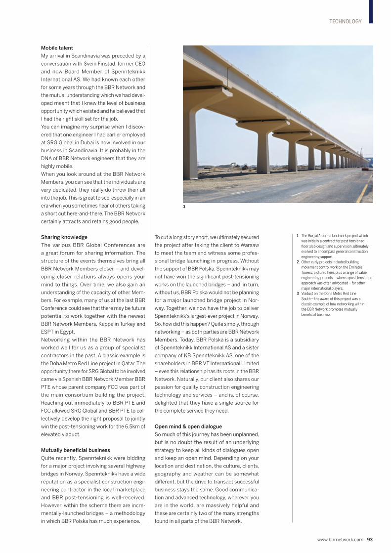
Mobile talent
My arrival in Scandinavia was preceded by a
conversation with Svein Finstad, former CEO
and now Board Member of Spennteknikk
International AS. We had known each other
for some years through the BBR Network and
the mutual understanding which we had devel-
oped meant that I knew the level of business
opportunity which existed and he believed that
I had the right skill set for the job.
You can imagine my surprise when I discov-
ered that one engineer I had earlier employed
at SRG Global in Dubai is now involved in our
business in Scandinavia. It is probably in the
DNA of BBR Network engineers that they are
highly mobile.
When you look around at the BBR Network
Members, you can see that the individuals are
very dedicated, they really do throw their all
into the job. This is great to see, especially in an
era when you sometimes hear of others taking
a short cut here-and-there. The BBR Network
certainly attracts and retains good people.
Sharing knowledge
The various BBR Global Conferences are
a great forum for sharing information. The
structure of the events themselves bring all
BBR Network Members closer – and devel-
oping closer relations always opens your
mind to things. Over time, we also gain an
understanding of the capacity of other Mem-
bers. For example, many of us at the last BBR
Conference could see that there may be future
potential to work together with the newest
BBR Network Members, Kappa in Turkey and
ESPT in Egypt.
Networking within the BBR Network has
worked well for us as a group of specialist
contractors in the past. A classic example is
the Doha Metro Red Line project in Qatar. The
opportunity there for SRG Global to be involved
came via Spanish BBR Network Member BBR
PTE whose parent company FCC was part of
the main consortium building the project.
Reaching out immediately to BBR PTE and
FCC allowed SRG Global and BBR PTE to col-
lectively develop the right proposal to jointly
win the post-tensioning work for the 6.5km of
elevated viaduct.
Mutually beneficial business
Quite recently, Spennteknikk were bidding
for a major project involving several highway
bridges in Norway. Spennteknikk have a wide
reputation as a specialist construction engi-
neering contractor in the local marketplace
and BBR post-tensioning is well-received.
However, within the scheme there are incre-
mentally-launched bridges – a methodology
in which BBR Polska has much experience.
To cut a long story short, we ultimately secured
the project after taking the client to Warsaw
to meet the team and witness some profes-
sional bridge launching in progress. Without
the support of BBR Polska, Spennteknikk may
not have won the significant post-tensioning
works on the launched bridges – and, in turn,
without us, BBR Polska would not be planning
for a major launched bridge project in Nor-
way. Together, we now have the job to deliver
Spennteknikk’s largest-ever project in Norway.
So, how did this happen? Quite simply, through
networking – as both parties are BBR Network
Members. Today, BBR Polska is a subsidiary
of Spennteknikk International AS and a sister
company of KB Spennteknikk AS, one of the
shareholders in BBR VT International Limited
– even this relationship has its roots in the BBR
Network. Naturally, our client also shares our
passion for quality construction engineering
technology and services – and is, of course,
delighted that they have a single source for
the complete service they need.
Open mind & open dialogue
So much of this journey has been unplanned,
but is no doubt the result of an underlying
strategy to keep all kinds of dialogues open
and keep an open mind. Depending on your
location and destination, the culture, clients,
geography and weather can be somewhat
different, but the drive to transact successful
business stays the same. Good communica-
tion and advanced technology, wherever you
are in the world, are massively helpful and
these are certainly two of the many strengths
found in all parts of the BBR Network.
www.bbrnetwork.com 93
TECHNOLOGY
1 The Burj al Arab – a landmark project which
was initially a contract for post-tensioned
floor slab design and supervision, ultimately
evolved to encompass general construction
engineering support.
2 Other early projects included building
movement control work on the Emirates
Towers, pictured here, plus a range of value
engineering projects – where a post-tensioned
approach was often advocated – for other
major international players.
3 Viaduct on the Doha Metro Red Line
South – the award of this project was a
classic example of how networking within
the BBR Network promotes mutually
beneficial business.
3

BBR DIRECTORY
94 CONNÆCT | Edition 14
HEADQUARTERS
BBR VT International Ltd Ringstrasse 2 8603 Schwerzenbach-Zurich Switzerland Tel +41 44 806 80 60 Fax +41 44 806 80 50 www.bbrnetwork.com [email protected]
EUROPE
AUSTRIA KB Vorspann-Technik GmbH Weitwörth 25 5151 Nussdorf a.H. Tel +43 6272 407 90 Fax +43 6272 407 90 11 www.kb-vt.com [email protected]
BOSNIA & HERZEGOVINA see Croatia
BULGARIA see Spain
CROATIA BBR Adria d.o.o. Kalinovica 3 10 000 Zagreb Tel +385 1 3839 220 Fax +385 1 3839 243 www.bbr-adria.com [email protected]
DENMARK see Norway
FINLAND see Norway
FRANCE ETIC S.A.S. 80 Boulevard du Général Leclerc F-78220 Viroflay Tel +33 1 39 50 11 20 www.etic-sas.fr [email protected]
GERMANY see Austria
KOSOVO see Croatia
LIECHTENSTEIN see Switzerland
LUXEMBOURG See France
MONTENEGRO see Croatia
NETHERLANDS Spanstaal – Ballast Nedam Infra Specialiteiten B.V. Nijverheidstraat 12 4143 HM Leerdam Post Address: PO Box 236 4140 AE Leerdam Tel +31 345 63 92 00 Fax +31 345 61 91 07 www.ballast-nedam.com [email protected]
NORWAY KB Spennteknikk AS Siva Industrial Estate Norvald Strands veg 19-21 Postboks 1213 2206 Kongsvinger Tel +47 62 81 00 30 Fax +47 62 81 00 55 www.spennteknikk.no [email protected]
POLAND BBR Polska Sp. z o.o. (Head Office) ul. Annopol 14, 03-236 Warszawa Tel +48 22 811 50 53 www.bbr.pl [email protected]
BBR Polska Sp. z o.o. ul. Tarnogórska 214a, 44-105 Gliwice Tel +48 32 331 47 98 www.bbr.pl [email protected]
PORTUGAL see Spain
ROMANIA see Spain
SERBIA see Croatia
SLOVENIA see Croatia
SPAIN FCC Construcción, S.A. Antigua Carretera N-IIIm Km. 31,150 28500 Arganda del Rey Madrid Tel +34 91 876 09 00 Fax +34 91 876 09 01 www.bbrpte.com [email protected]
SWEDEN Spännteknik SLF AB Koppsängsvägen 13 671 93 Arvika Tel +46 8 510 678 10 Fax +46 8 510 678 19 www.spannteknik.se [email protected]
SWITZERLAND Stahlton AG Hauptstrasse 131, 5070 Frick Tel +41 44 938 99 00 Fax +41 44 938 99 01 www.stahlton.ch [email protected]
TURKEY Kappa Kalip Insaat Ve Taahhut A.S. Beytepe Mah. 5387. cad, Mira Ofis A Blok No: 15/49 06800 Çankaya/Ankara Tel +90 312 963 00 33 www.kappa.gen.tr [email protected]
AMERICAS
EASTERN CANADA Canadian bbr Inc. 3450 Midland Ave. Scarborough, Ontario M1V 4V4 Tel +1 416 291 1618 Fax +1 416 291 9960 [email protected]
AFRICA
EGYPT ESPT 43 Moez Al Dawla Street Nasr city, Cairo Tel +20 106 094 1272 +20 100 450 5820 Fax +20 2 267 102 51 www.bbr-espt.com [email protected]
Our global presenceOur clients are based in over 50 countries – so our
global presence is a vital asset.
We can share our international experience locally,
provide solutions adapted to specific conditions
and be on hand to offer a personalized service.EUROPE
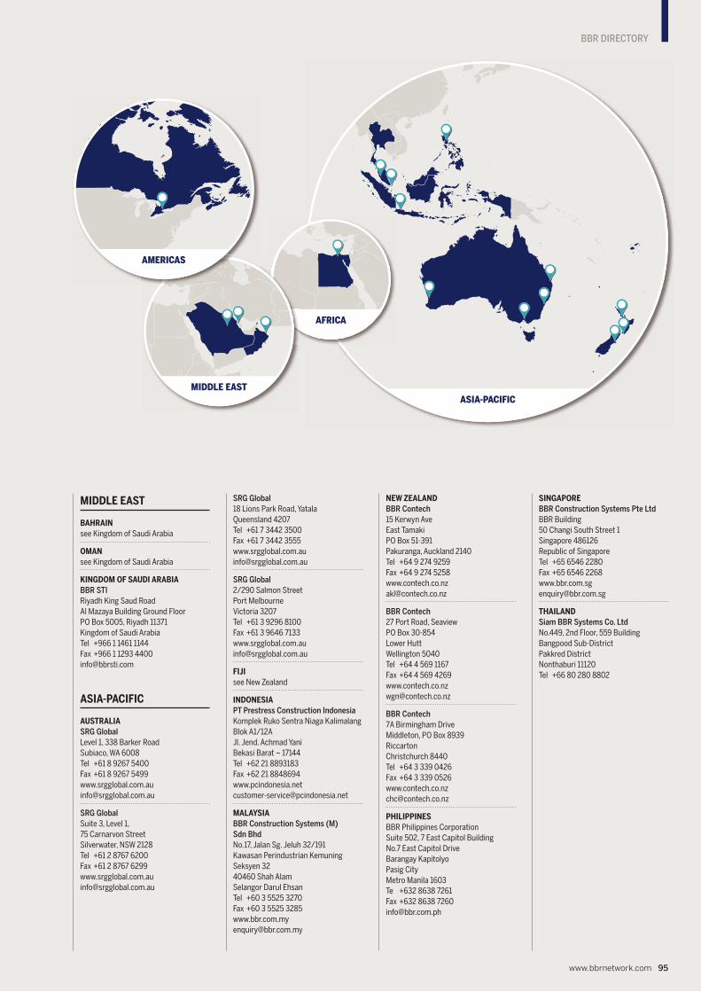
BBR DIRECTORY
www.bbrnetwork.com 95
MIDDLE EAST
BAHRAIN see Kingdom of Saudi Arabia
OMAN see Kingdom of Saudi Arabia
KINGDOM OF SAUDI ARABIA BBR STI Riyadh King Saud Road Al Mazaya Building Ground Floor PO Box 5005, Riyadh 11371 Kingdom of Saudi Arabia Tel +966 1 1461 1144 Fax +966 1 1293 4400 [email protected]
ASIA-PACIFIC
AUSTRALIA SRG Global Level 1, 338 Barker Road Subiaco, WA 6008 Tel +61 8 9267 5400 Fax +61 8 9267 5499 www.srgglobal.com.au [email protected]
SRG Global Suite 3, Level 1, 75 Carnarvon Street Silverwater, NSW 2128 Tel +61 2 8767 6200 Fax +61 2 8767 6299 www.srgglobal.com.au [email protected]
SRG Global 18 Lions Park Road, Yatala Queensland 4207 Tel +61 7 3442 3500 Fax +61 7 3442 3555 www.srgglobal.com.au [email protected]
SRG Global 2/290 Salmon Street Port Melbourne Victoria 3207 Tel +61 3 9296 8100 Fax +61 3 9646 7133 www.srgglobal.com.au [email protected]
FIJI see New Zealand
INDONESIA PT Prestress Construction Indonesia Komplek Ruko Sentra Niaga Kalimalang Blok A1/12A Jl. Jend. Achmad Yani Bekasi Barat – 17144 Tel +62 21 8893183 Fax +62 21 8848694 www.pcindonesia.net [email protected]
MALAYSIA BBR Construction Systems (M) Sdn Bhd No.17, Jalan Sg. Jeluh 32/191 Kawasan Perindustrian Kemuning Seksyen 32 40460 Shah Alam Selangor Darul Ehsan Tel +60 3 5525 3270 Fax +60 3 5525 3285 www.bbr.com.my [email protected]
NEW ZEALAND BBR Contech 15 Kerwyn Ave East Tamaki PO Box 51-391 Pakuranga, Auckland 2140 Tel +64 9 274 9259 Fax +64 9 274 5258 www.contech.co.nz [email protected]
BBR Contech 27 Port Road, Seaview PO Box 30-854 Lower Hutt Wellington 5040 Tel +64 4 569 1167 Fax +64 4 569 4269 www.contech.co.nz [email protected]
BBR Contech 7A Birmingham Drive Middleton, PO Box 8939 Riccarton Christchurch 8440 Tel +64 3 339 0426 Fax +64 3 339 0526 www.contech.co.nz [email protected]
PHILIPPINES BBR Philippines Corporation Suite 502, 7 East Capitol Building No.7 East Capitol Drive Barangay Kapitolyo Pasig City Metro Manila 1603 Te +632 8638 7261 Fax +632 8638 7260 [email protected]
SINGAPORE BBR Construction Systems Pte Ltd BBR Building 50 Changi South Street 1 Singapore 486126 Republic of Singapore Tel +65 6546 2280 Fax +65 6546 2268 www.bbr.com.sg [email protected]
THAILAND Siam BBR Systems Co. Ltd No.449, 2nd Floor, 559 Building Bangpood Sub-District Pakkred District Nonthaburi 11120 Tel +66 80 280 8802
ASIA-PACIFIC
AFRICA
MIDDLE EAST
AMERICAS

CO
NN
ÆC
T
Th
e m
agaz
ine
of t
he
Glo
bal
BB
R N
etw
ork
of E
xper
ts
2020