the luenberger-peng observer analysis for sensorless
TRANSCRIPT
Annals of the University of Petrosani, Electrical Engineering, 22 (2020)
THE LUENBERGER-PENG OBSERVER ANALYSIS FOR
SENSORLESS VECTOR CONTROL SYSTEMS OF
INDUCTION MOTORS
OLIMPIU STOICUTA1
Abstract: The article presents the analysis by numerical simulation in Matlab-
Simulink of the rotor's flux Luenberger observer assembly coupled with a Peng speed observer.
The proposed estimator is use in sensorless vector systems of induction motors.
Keywords: induction motors, sensorless vector control systems, observers.
1. INTRODUCTION
The dynamic performances of sensorless vector control systems depends on
the accuracy of the online estimates made by the observers used. The best-known observers used in sensorless vector control systems are
extended Luenberger observer [10], [11], [12], extended Kalman filter [6], [8], MRAS
observer [19], [22], extened Gopinath observer [14], [15], [21], MRAS speed observer
coupled with rotor flux Gopinath reduced-order observer [7], [30], and Peng speed
observer [17], [18] coupled with rotor flux Gopinath reduced-order observer [27].
The above-mentioned estimators are sensitive to changes in the electrical
parameters of the induction motor and have stability problems in the area of very low
operating speeds [3], [16], [22], [28].
Research in the last three decades in the field of sensorless vector control
systems of the induction motor has focused on reducing the problems mentioned
above, [20], [25], [26], [29]. In this regard, the article proposes a method for
simultaneously estimating the speed, modulus and position of the rotor's flux phasor
using a Luenberger rotor flux observer coupled with the Peng speed observer.
The proposed estimator is study in Matlab – Simulink. The article presents in
detail the implementation in an S-Function block of the Luenberger observer, adapted
according to the estimated speed with the Peng observer.
1 Associate Proffesor Eng. , Ph.D. at the University of Petroşani.
OLIMPIU STOICUTA
2. MATHEMATICAL MODEL OF THE INDUCTION MOTOR
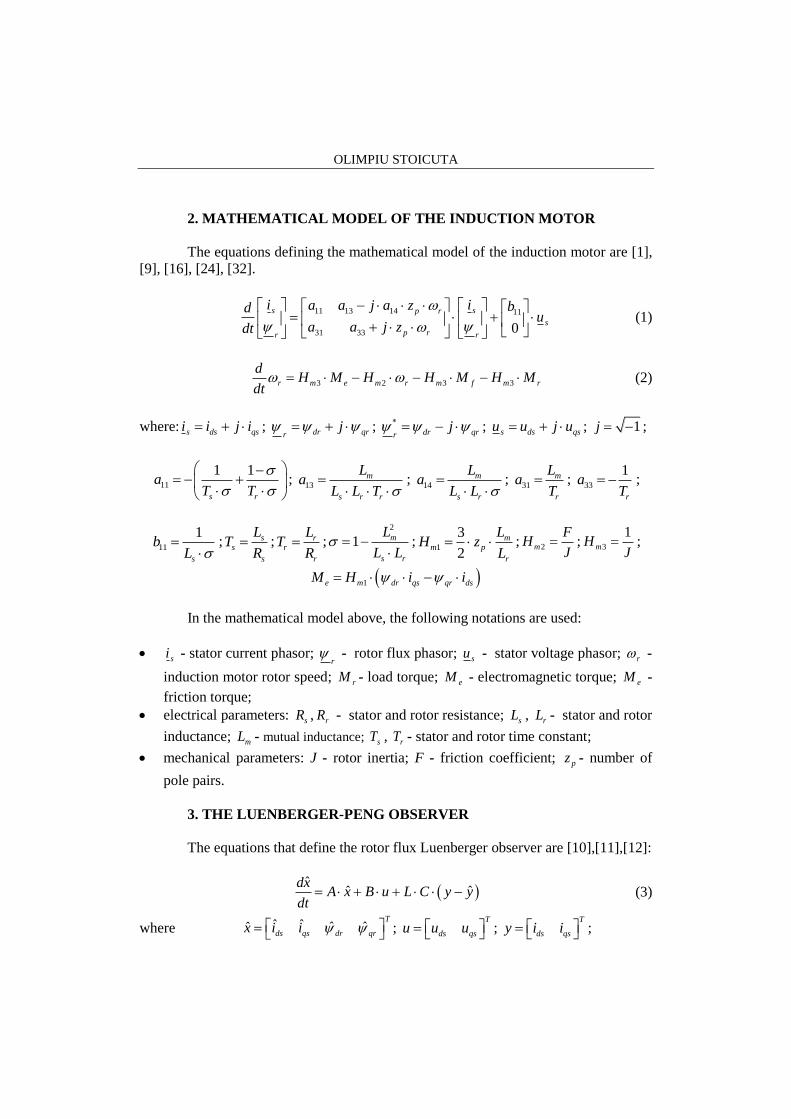
The equations defining the mathematical model of the induction motor are [1],
[9], [16], [24], [32].
11 13 14 11
31 33 0
s sp r
s
p rr r
i ia a j a z bdu
a a j zdt
(1)
3 2 3 3r m e m r m f m r
dH M H H M H M
dt (2)
where: s ds qsi i j i ; dr qrrj ; dr qrr
j ; s ds qsu u j u ; 1j ;
11
1 1
s r
aT T
;
13m
s r r
La
L L T
;
14m
s r
La
L L
;
31m
r
La
T ;
33
1
r
aT
;
11
1
s
bL
; ss
s
LT
R ; r
r
r
LT
R ;
2
1 m
s r
L
L L
;
1
3
2
mm p
r
LH z
L ; 2m
FH
J ; 3
1mH
J ;
1e m dr qs qr dsM H i i
In the mathematical model above, the following notations are used:
si - stator current phasor; r
- rotor flux phasor; su - stator voltage phasor; r -
induction motor rotor speed; rM - load torque; eM - electromagnetic torque; eM -
friction torque;
electrical parameters: sR , rR - stator and rotor resistance; sL , rL - stator and rotor
inductance; mL - mutual inductance; sT , rT - stator and rotor time constant;
mechanical parameters: J - rotor inertia; F - friction coefficient; pz - number of
pole pairs.
3. THE LUENBERGER-PENG OBSERVER
The equations that define the rotor flux Luenberger observer are [10],[11],[12]:
ˆ
ˆ ˆdx
A x B u L C y ydt
(3)
where ˆ ˆ ˆ ˆˆT
ds qs dr qrx i i ; T
ds qsu u u ; T
ds qsy i i ;
THE LUENBERGER-PENG OBSERVER ANALYSIS FOR SENSORLESS VECTOR
CONTROL SYSTEMS OF INDUCTION MOTORS
11 13 14
11 14 13
31 33
31 33
ˆ0
ˆ0
ˆ0
ˆ0
p r
p r
p r
p r
a a a z
a a z aA
a a z
a z a
;
11
11
0
0
0 0
0 0
b
bB
; 1 0 0 0
0 1 0 0C
;
11
1 1
s r
aT T
;
13m
s r r
La
L L T
;
14m
s r
La
L L
;
31m
r
La
T ;
33
1
r
aT
;
11
1
s
bL
; ss
s
LT
R ; r
r
r
LT
R ;
2
1 m
s r
L
L L
.
The coefficients of the Luenberger amplification matrix are:
11 12
12 11
21 22
22 21
la la
la laL
la la
la la
(4)
The elements of Luenberger matrix are [10], [11]:
11 11 33
12
22 12
2
21 31 11 11
1
ˆ 1
1
p r
la k a a
la z k
la la
la a a k la
(5)
where 141/ a , and k is the proportionality factor between the eigenvalues of the
estimator and the eigenvalues of the induction machine ( 0k ).
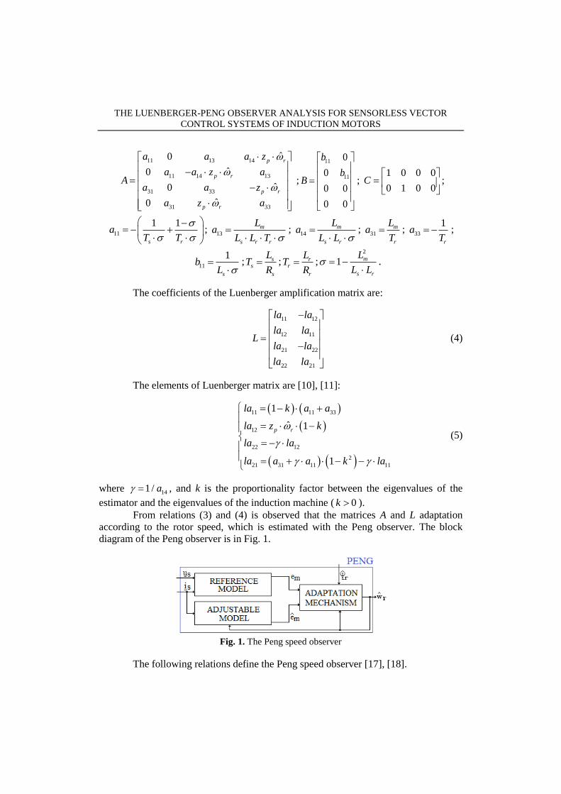
From relations (3) and (4) is observed that the matrices A and L adaptation
according to the rotor speed, which is estimated with the Peng observer. The block
diagram of the Peng observer is in Fig. 1.
Fig. 1. The Peng speed observer
The following relations define the Peng speed observer [17], [18].
OLIMPIU STOICUTA
The reference model
sm s ss s
die u R i L
dt (6)
The adjustable model
2
1 1ˆˆ m
m m m sp r
r r r
Le j z i i i
L T T
(7)
The adaptation mechanism [18]
0
ˆt
r p ik k dt (8)
where: m dm qme e j e ; ˆ ˆ ˆm dm qme e j e ; s ds qsi i j i ; m dm qmi i j i ;
a a bk ; ˆa r p rk T z ; 2 1
ˆ ˆa dr qre e ; 1 2
ˆ ˆb dr qre e ;
1ˆ
dm dme e e ; 2ˆ
qm qme e e .
In relation (7), mi represent of the magnetization current phasor
1 1ˆm
m m sp r
r r
dij z i i i
dt T T (9)
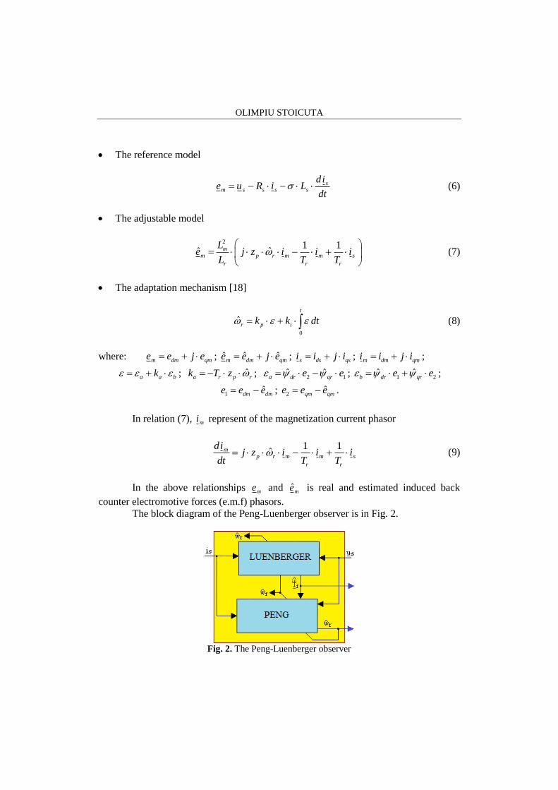
In the above relationships me and ˆme is real and estimated induced back
counter electromotive forces (e.m.f) phasors. The block diagram of the Peng-Luenberger observer is in Fig. 2.
Fig. 2. The Peng-Luenberger observer
THE LUENBERGER-PENG OBSERVER ANALYSIS FOR SENSORLESS VECTOR
CONTROL SYSTEMS OF INDUCTION MOTORS
The adjustable model of Peng observer and Luenberger observer are adapted
according to the estimated speed of the induction motor.
4. THE MATLAB-SIMULINK SIMULATION PROGRAM OF THE
LUENBERGER-PENG OBSERVER
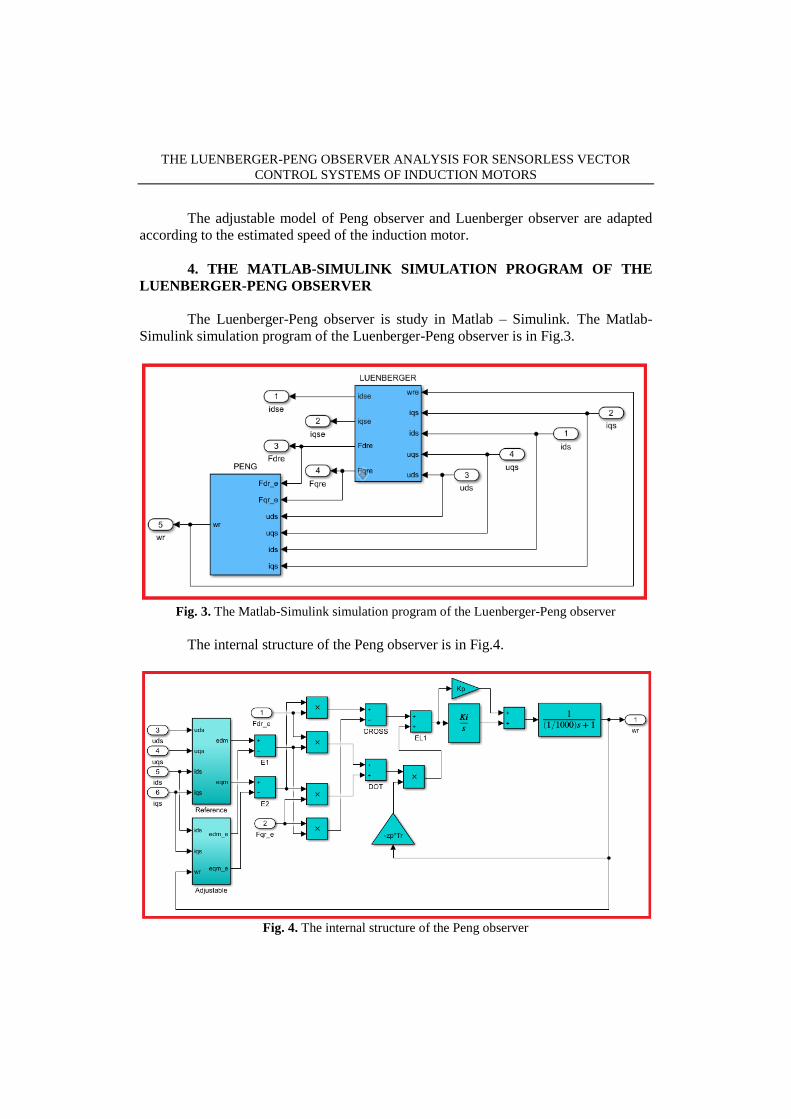
The Luenberger-Peng observer is study in Matlab – Simulink. The Matlab-
Simulink simulation program of the Luenberger-Peng observer is in Fig.3.
Fig. 3. The Matlab-Simulink simulation program of the Luenberger-Peng observer
The internal structure of the Peng observer is in Fig.4.
Fig. 4. The internal structure of the Peng observer

OLIMPIU STOICUTA
On the other hand, the reference model and the adjustable model from the Peng
obsererver's component are in Fig.5
Fig. 5. The reference model (a) and the adjustable model (b) from the Peng observer.
The Luenberger observer is implemented in Matlab-Simulink based on an S-Function
block [23], [24], [33]. The internal structure of the Luenberger block is shown in Fig.6.
Fig. 6. Luenberger observer internal structure
The S-Function block which implements the Luenberger estimator is denoted
“L1” in Fig.6.
The following figure shows the M-File code associated with this block.

THE LUENBERGER-PENG OBSERVER ANALYSIS FOR SENSORLESS VECTOR
CONTROL SYSTEMS OF INDUCTION MOTORS
Fig. 7. The M-File code of the “L1” block.
The estimated speed of the adaptation mechanism of the Peng observer is
filtered through a low pass filter (see Fig. 4).
OLIMPIU STOICUTA
5. THE SIMULATION RESULTS
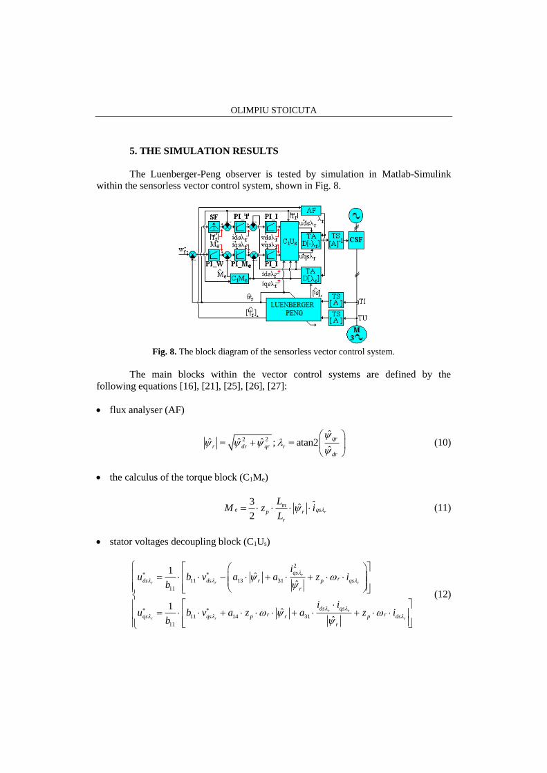
The Luenberger-Peng observer is tested by simulation in Matlab-Simulink
within the sensorless vector control system, shown in Fig. 8.
Fig. 8. The block diagram of the sensorless vector control system.
The main blocks within the vector control systems are defined by the
following equations [16], [21], [25], [26], [27]:
flux analyser (AF)
2 2ˆ
ˆ ˆ ˆ ; atan2ˆ
qr
r dr qr r
dr
(10)
the calculus of the torque block (C1Me)
3ˆ
2r
me qsp r
r
LM z i
L (11)
stator voltages decoupling block (C1Us)
2
11 13 31
11
11 14 31
11
1ˆ
ˆ
1ˆ
ˆ
r
r r r
r r
r r r
qsrds ds r p qs
r
ds qsr rqs qs p r p ds
r
iu b v a a z i
b
i iu b v a z a z i
b
(12)
THE LUENBERGER-PENG OBSERVER ANALYSIS FOR SENSORLESS VECTOR
CONTROL SYSTEMS OF INDUCTION MOTORS
the field weakening block (SF)
max
max
2 2 2
2ˆf
2 60
otherwiseˆ1
Nr
N
rm
s p r r
U ni
f
L U
R z T
(13)
where: max
2
3NU U ; UN is the rated voltage; fN is rated frequency; nN [rpm] is the
rated speed of the induction motor.
The five automatic controllers of the sensorless vector control system are
Proportional Integral-type (PI) [13].
1
1n
n
G s KT s
; 1,2,3,4,5n (14)
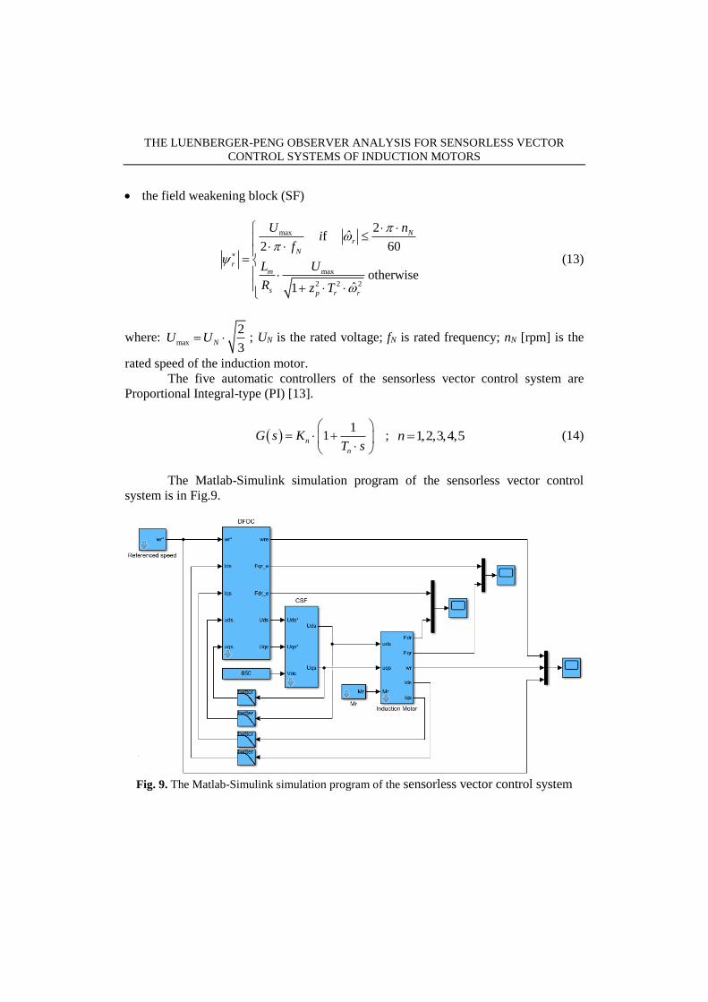
The Matlab-Simulink simulation program of the sensorless vector control
system is in Fig.9.
Fig. 9. The Matlab-Simulink simulation program of the sensorless vector control system

OLIMPIU STOICUTA
The transistors within the static frequency converter with intermediary
continuous voltage circuit are considered of ideal commutation. Within simulation, the
CSF disregards the mathematical models of the semiconducting devices.
Within the PWM modulator, the carrier is of isosceles triangle type having a
frequency of 5 [kHz]. The modulation technique is based on a modified suboscillation
method. This way, over the stator's reference voltages is injected the 3rd degree
harmonic of the phase voltage, having amplitude of 1/6 of the fundamental reference
voltage [5].
The sensorless vector control system are simulated in Matlab-Simulink using
an induction motor of 4 [kW]. The electrical and mechanical parameters of the
induction motor are given in the Table 1.
Table 1. Induction Motor Parameters
Name Value Name Value
Rs Stator resistance 1.405 [Ω] PN Rated power 4 [kW]
Rr Rotor resistance 1.395 [Ω] nN Rated speed 1430[rpm]
Ls Stator inductance 0.178039 [H] zp Number of pole pairs 2
Lr Rotor inductance 0.178039 [H] fN Rated frequency 50 [Hz]
Lm Mutual inductance 0.1722 [H] UN Rated voltage 400 [V] Y
J Motor rotor inertia 0.0131[kg·m2] MN Rated torque 27 [N·m]
F Friction coefficient 0.002985 [N·m·s/rad] Mf Friction torque 3.4 [N·m]
The internal structure of the control block with with direct orientation after
rotor field (DFOC), is presented in Fig.10.
Fig. 10. The Matlab-Simulink program of the DFOC block

THE LUENBERGER-PENG OBSERVER ANALYSIS FOR SENSORLESS VECTOR
CONTROL SYSTEMS OF INDUCTION MOTORS
Because the first frequency which appears in the stator voltages spectrum is the
triangular waveform frequency, both the currents and the stator voltages will be filtered
with two pole Butterworth filters, which have de cutoff frequency set 500 [Hz].
The cutoff frequency of the filters is correlated with the frequency of the
triangular signal within the inverter, in order to have an optimal aliasing.
The Dormand – Prince (ode45) method is used in the simulation, with a
relative and absolute error of 610 .
The rest of the constants used within the simulation are presented in Table 2.
Table 2. Simulation Parameters
Name Value Obs.
K1 Parameter of proportionality 370.5764 The rotor flux controller
T1 Time of integration 0.1276
K2 Parameter of proportionality 0.0442 The torque controller
T2 Time of integration 0.001
K3 Parameter of proportionality 0.8733 The speed controller
T3 Time of integration 0.0298
K4; K5 Parameter of proportionality 11.4865 The current controllers
T4 ;T5 Time of integration 0.0042
kp Parameter of proportionality 462.6377 Adaptation mechanism of
Peng observer ki Parameter of integration 3624933
k Parameter of proportionality 1.2 The Luenberger observer
The simulated program from Fig.9, was compiled and ran on a numeric system
operating Windows 10- 64b. The hardware structure of the system is built around an
I7-4720HQ processor (2.6GHz), with 8 GB of available RAM.
The Luenberger-Peng Observatory was analyzed in two cases:
Case 1. When the vector control system operates in the area of low speeds (60
rpm) and medium speeds (1000 rpm). In this case, the electrical parameters of the
induction motor are unaltered.
Case 2. When the vector control system operates in the area of low speeds (60
rpm) and medium speeds (1000 rpm). In this case, it is considered that the
induction motor is preheated. As such, in the initial moment, the rotor resistance is
considered with 5% higher than the rated value.
In simulation test when the vector control system operates at medium speeds
(1000 rpm), the induction motor is functioning under load, having at its ax a load
torque equal to that of the rated torque of the induction motor.
When the vector control system operates at low speeds (60 rpm), the induction
motor is functioning under load, having at its ax a load torque equal to 5 Nm.
For each analyzed case, the time variation of the imposed, estimated and
measured speed of the induction motor is highlighted, as well as the time variation of

OLIMPIU STOICUTA
the imposed, estimated and real rotor flux phasor module. The obtained results are
presented in the following figures.
Fig. 11. Simulation results – Case 1
From the Fig.11, it is observed that the modulus of the rotor flux phasor is
estimated very well, the stationary error being a very small one. In the transient period
the estimated rotor flux phasor module has an overshoot of 54%. In the case of the
rotor flux phasor modulus, the settling time is 0.03 [s].
On the other hand, from Fig.11 it is observed that the stationary error of the
estimated/measured speed of the induction motor is a small one. Notable differences
occur during the start of the induction motor. Disturbance (load torque) rejection time
is approximately 0.15[s].
The maximum deviation of the estimated/real speed from the imposed speed
when starting of the induction motor is 250 rpm (case 1.a), respectively 61 rpm (case
1.b). On the other hand, overshoot obtained at time 0.32 [s], is 4.5%. In the case of the
speed, the settling time is 0.1 [s].
THE LUENBERGER-PENG OBSERVER ANALYSIS FOR SENSORLESS VECTOR
CONTROL SYSTEMS OF INDUCTION MOTORS
In order to obtain better transient dynamic performances two-degrees-of-
freedom PI speed controllers with can be used [2], [4], [31].
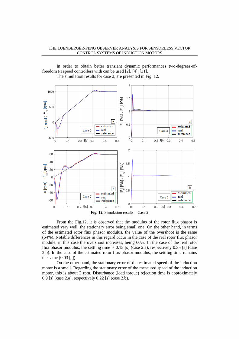
The simulation results for case 2, are presented in Fig. 12.
Fig. 12. Simulation results – Case 2
From the Fig.12, it is observed that the modulus of the rotor flux phasor is
estimated very well, the stationary error being small one. On the other hand, in terms
of the estimated rotor flux phasor modulus, the value of the overshoot is the same
(54%). Notable differences in this regard occur in the case of the real rotor flux phasor
module, in this case the overshoot increases, being 60%. In the case of the real rotor
flux phasor modulus, the settling time is 0.15 [s] (case 2.a), respectively 0.35 [s] (case
2.b). In the case of the estimated rotor flux phasor modulus, the settling time remains
the same (0.03 [s]).
On the other hand, the stationary error of the estimated speed of the induction
motor is a small. Regarding the stationary error of the measured speed of the induction
motor, this is about 2 rpm. Disturbance (load torque) rejection time is approximately
0.9 [s] (case 2.a), respectively 0.22 [s] (case 2.b).
OLIMPIU STOICUTA
The maximum deviation of the measured speed from the imposed speed when
starting of the induction motor is 145 rpm (case 2.a), respectively 55 rpm (case 2.b).
On the other hand, the maximum deviation of the estimated speed from the
imposed speed when starting of the induction motor is 340 rpm (case 2.a), respectively
227 rpm (case 2.b). The overshoot obtained at time 0.32 [s], is 4.1%. In the case of the
speed, the settling time is 0.1 [s].
In this case, in order to increase the dynamic performances, a Luenberger-Peng
observer can be made that adapts according to the rotor resistance.
6. CONCLUSIONS
Very good dynamic performances of the Luenberger-Peng observer make it a
very good solution in sensorless vector control systems, when you want to estimate in
tandem the speed, modulus and position of the rotor flux phasor of the induction
motor.
Compared to the speed observer proposed by C. Schauder, the Luenberger-
Peng observer has no problems with pure integration within the reference model.
Compared to the adaptation mechanism of the extended Luenberger observer
(ELO) proposed by H. Kubota and adaptation mechanism of the MRAS observer
proposed by C. Schauder, the Peng speed observer is more complex, requiring a
number of more mathematical operations.
Following the tests performed, we can say that the Luenberger-Peng observer
is less robust to the variation of the rotor resistance, compared to the ELO observer and
the MRAS observer. This disadvantage can be eliminated by means of a Luenberger-
Peng observer that adapts according to the stator resistance and the rotor resistance.
The simulation programs used to test the Luenberger-Peng observer are
presented in detail offering a useful support for experts within automations and
electrical engineering.
REFERENCES
[1]. Boldea I., Nasar S.A., Vector Control of AC Drives, CRC Press, 1992.
[2]. Gogea A., Stoicuta O., Pana T., Comparative Analysis Between the PI
Speed Controller and Two-Degrees-of-Freedom Speed Controller for Induction Motor
Drive, Proc. IEEE of MPS, Cluj-Napoca, Romania, pp.1-6, 2019.
[3]. Gogea A., Stoicuta O., Pana T., Paramon A., Comparative Study a Two
Adaptive Observers of Speed and Rotor Flux of the Induction Motor, 2019 8th International
Conference on Modern Power Systems (MPS), Cluj Napoca, Romania, pp. 1-8, 2019.
[4]. Harnefors L., Saarakkala S.E., Hinkkanen M., Speed Control of Electrical
Drives Using Classical Control Methods, IEEE Transactions on Industry Applications, vol.
49, no. 2, pp. 889-898, 2013.
[5]. Holtz J., Pulsewidth Modulation for Electronic Power Conversion,
Proceedings of IEEE, vol.82, No.8, pp.1194 - 1214, 1994.
[6]. Holtz J., Sensorless Control of Induction Motor Drives, Proceedings of
IEEE, vol.90, No.8, pp.1359 - 1394, 2002.

THE LUENBERGER-PENG OBSERVER ANALYSIS FOR SENSORLESS VECTOR
CONTROL SYSTEMS OF INDUCTION MOTORS
[7]. Hori Y., Umeno T., Implementation of Robust Flux Observer based Field
Orientation (FOFO) Controller for Induction Machines, Proc. IEEE of IAS Annual
Meeting, San Diego, USA, pp.523-528, 1989.
[8]. Kim Y.R., Sul S.K., Park M.H., Speed Sensorless Vector Control of
Induction Motor Using Extended Kalman Filter, IEEE Trans. Ind. Application, vol.30,
No.5, pp. 1225-1233, 1994.
[9]. Kelemen A., Imecs M., Field-Oriented AC Electrical Drives, Romania
Academy Publishing House, Bucharest, 1989.
[10]. Kubota H., Matsuse K., Nakano T., DSP-Based Speed Adaptive Flux
Observer of Induction Motor, IEEE Transactions on Industry Applications, vol. 29, No. 2,
pp.344 - 348, 1993.
[11]. Kubota H., Matsuse K., Speed Sensorless Field-Oriented Control of
Induction Motor with Rotor Resistance Adaptation, IEEE Trans. Industry Application, vol.
30, No.5, pp. 1219–1224, 1994.
[12]. Kubota H., Matsuse K., Speed Sensorless Field Oriented Control of
Induction Machines using Flux Observer, Proceedings of IECON'94 - 20th Annual
Conference of IEEE Industrial Electronics, Bologna, Italy, vol.3, pp. 1611-1615, 1994.
[13]. Pana T, Stoicuta O., Controllers Tuning for the Speed Vector Control of
Induction Motor Drive Systems, Proc. IEEE of AQTR, Cluj-Napoca, Romania, pp.1-6,
2010.
[14]. Pana T., Stoicuta O., Design of a new Adaptive Observer for Sensorless
Induction Motor Drive, Annals of the University of Craiova – Electrical Engineering,
pp.73-78, 2010.
[15]. Pana T., Stoicuta O., Small Speed Asymptotic Stability Study of an Induction
Motor Sensorless Speed Control System with Extended Gopinath Observer, Journal of
Advances in Electrical and Computer Engineering, vol.11, No.2, pp.15-22, 2011.
[16]. Pana T., Stoicuta O., Stability of the Vector Drive Systems with Induction
Motors, Mediamira Publishers, 2016.
[17]. Peng F.Z., Fukao T., Robust Speed Identification for Speed-Sensorless
Vector Control of Induction Motors, IEEE Trans. Ind. Application, vol. 30, No.5, pp. 1234-
1240, 1994.
[18]. Rashed M., Stronach A.F., A Stable Back-EMF MRAS-Based Sensorless
Low-Speed Induction Motor Drive Insensitive to Stator Resistance Variation, IEEE Proc.
Electr. Power Appl., vol.151, No.6, 2004.
[19]. Schauder C., Adaptive Speed Identification for Vector Control of Induction
Motors without Rotational Transducers, IEEE Trans. Ind. Application, vol.28, No.5, pp.
1054-1061,1992.
[20]. Stoicuta O., Pana T., Speed and rotor flux observer for sensorless induction
motor drives, Proc. of AQTR, Cluj-Napoca, Romania, pp.68- 73, 2012.
[21]. Stoicuta O., Pana T., Molnar R., Simultaneous Estimation of Speed and
Rotor Resistance in the Sensorless Vector Control Systems with an Induction Motor, Based
on Extended Gopinath Observer, Acta Electrotechnica, vol.57, No.3, pp. 427-432, 2016.
[22]. Stoicuta O., Pana T., Asymptotic Stability Study of Induction Motor
Sensorless Vector Control Systems with MRAS Observer, Proc. IEEE of AQTR, Cluj-
Napoca, Romania, pp.1-6, 2016.
[23]. Stoicuta O., The Utilization of the S-Function Block in Simulation of the
Luenberger Rotor Flux Observer for Induction Motors, Annals of the University of
Petrosani – Electrical Engineering, No.18, pp.31-46, 2016.
OLIMPIU STOICUTA
[24]. Stoicuta O., The Utilization of the S-Function Block in Simulation of the
Mathematical Model of Induction Motor with Iron Loss, Annals of the University of
Petrosani – Electrical Engineering, No.18, pp.5-20, 2016.
[25]. Stoicuta O., Pana T., Molnar R., Deaconu D., Simultaneous Estimation of
Speed and Rotor Resistance in the Sensorless Vector Control Systems with Induction
Motors, 2017 International Conference on Electromechanical and Power Systems
(SIELMEN), Iasi, pp.47-52, 2017.
[26]. Stoicuta O., Pana T., Molnar R., Andras E.S., Deaconu D., Online
Compensation of Effects Caused of the Induction Motor Electrical Parameters Variations
for Extended Luenberger Observer, Bulletin of the Polytechnic Institute of Jassy, vol 64
(68), No.1, 2018.
[27]. Stoicuta O., Pana T., Comparative Study Between Extended Gopinath
Observer and Back EMF-MRAS Speed Observer Coupled with Gopinath Rotor Flux
Observer for Sensorless Vector Control of Induction Motor Drives, 2019 International
Conference on Electromechanical and Energy Systems (SIELMEN), Craiova, Romania, pp.
1-6, 2019.
[28]. Stoicuta O., Pana T.C., Asymptotic Stability Study of Induction Motor
Vector Control Systems with Luemberger Observer, 2008 IEEE International Conference
on Automation, Quality and Testing, Robotics, Cluj-Napoca, pp. 242-247, 2008.
[29]. Stoicuta O., Pana T., New Adaptive Observer for Sensorless Induction
Motor Drives, Annals of the Univ. Eftimie Murgu of Resita, No.2, pp.175- 186, 2014.
[30]. Tajima H., Hori Y., Speed Sensorless Field Orientation Control of the
Induction Machine, IEEE Trans. Ind. Application, vol. 29, No.1, pp.175-180, 1993.
[31]. Zaky M., Touti E., Azazi H., Two-Degrees of Freedom and Variable
Structure Controllers for Induction Motor Drives, Advances in Electrical and Computer
Engineering, vol.18, No.1, pp.71-80, 2018.
[32]. Vas P., Sensorless Vector and Direct Torque Control, Oxford Univ. Press,
1998.
[33]. ****, Simulink User’s Guide, MathWorks, 2017.