the low motion floater (lmf) · the lm fpso design features slide 6 square or rectangular shaped...
TRANSCRIPT
www.intecsea.com
INSTRUCTIONS FOR CHANGING COVER IMAGES:
1. Select both images by holding down
the ‘Ctrl’ button
2. Go to DRAWING TOOLS 3. Click the arrow next to SHAPE FILL 4. Click PICTURE 5. Locate the folder that contains the picture you want to
use and click INSERT
INSTRUCTIONS TO RESIZE AND REPOSITION YOUR IMAGE: 1. Click the image you want to edit
2. Go to PICTURE TOOLS 3. To maintain the original size and format
of the image, click the arrow under CROP and click
FIT
4. To reposition or resize your image, click CROP, and
use the circles on the edge of the image
The Low Motion Floater (LMF) Low Motion = Low Cost
Chunfa Wu, Vice President Floating Systems
Alaa Mansour, Marine Engineering Manager
Yuriy Drobyshevski, Floating Systems, ANZ

Outline
Pros and Cons of Conventional FPSO
The Low Motion Floater (LMF)
Design
Performance
Construction, Transportation & Installation
Risks and Mitigation Measures
Main Technical and Economical Advantages
Application to FLNG
Development Status
Slide 2

Pros and Cons of Conventional FPSO
High oil storage capacity
Suitable for remote fields with little or no infrastructures
High topside payload capacity
Relatively straightforward fabrication and installation; quayside integration
Most popular FPS with more than 60% market share
Unsuitable for SCRs except of very mild environment and narrow range of water depths Limited riser solutions
Unsuitable for TTR and requires a separate Dry Tree Unit if direct vertical access to wells is needed
Require turret and swivel in medium and harsh environment Complex component, design limitations, cost and schedule impact
Most of the above are caused by: high heave, roll and pitch motions
Slide 3
LM FPSO can preserve the pros and eliminate the cons
Pros:
Cons:
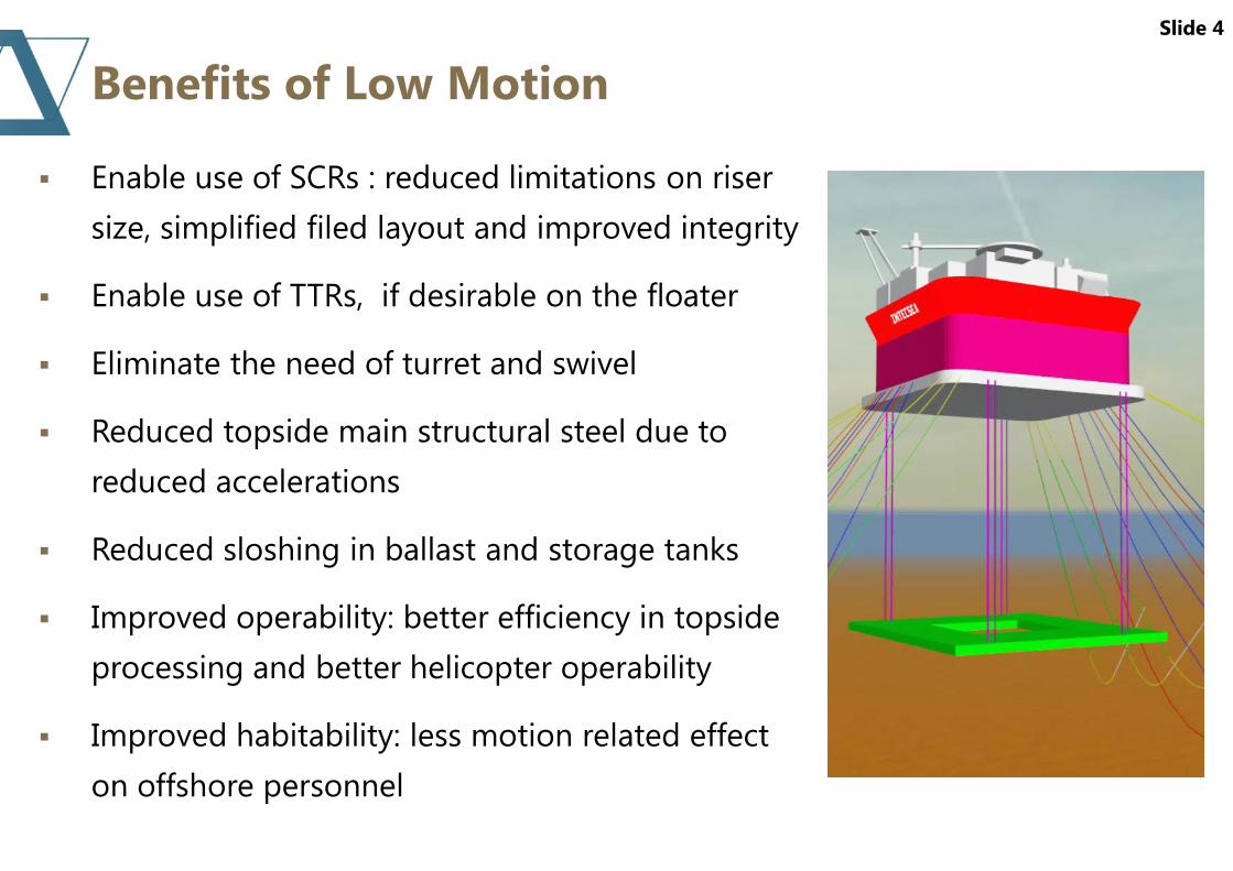
Benefits of Low Motion
Slide 4
Enable use of SCRs : reduced limitations on riser
size, simplified filed layout and improved integrity
Enable use of TTRs, if desirable on the floater
Eliminate the need of turret and swivel
Reduced topside main structural steel due to
reduced accelerations
Reduced sloshing in ballast and storage tanks
Improved operability: better efficiency in topside
processing and better helicopter operability
Improved habitability: less motion related effect
on offshore personnel
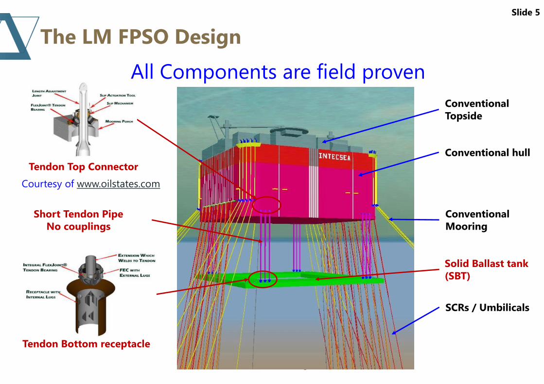
The LM FPSO Design
5
Conventional hull
Conventional
Topside
Conventional
Mooring
Short Tendon Pipe
No couplings
Solid Ballast tank
(SBT)
Tendon Top Connector
Tendon Bottom receptacle
SCRs / Umbilicals
Slide 5
All Components are field proven
Courtesy of www.oilstates.com
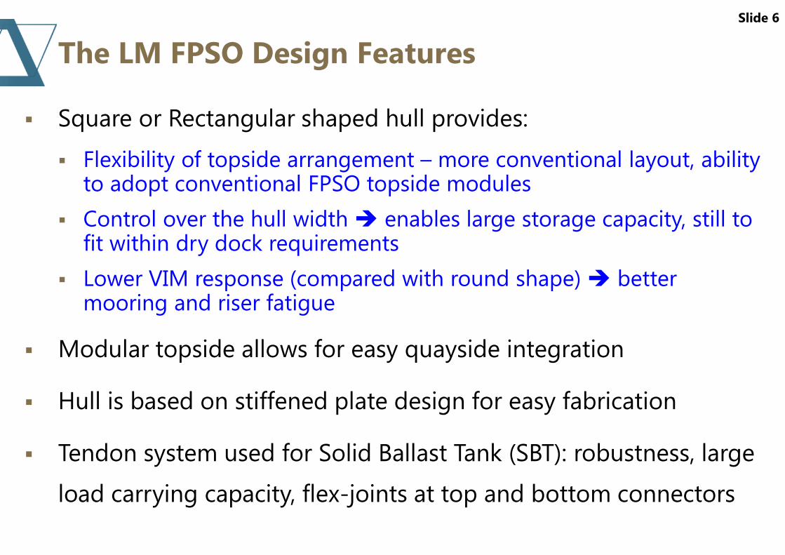
The LM FPSO Design Features
Slide 6
Square or Rectangular shaped hull provides:
Flexibility of topside arrangement – more conventional layout, ability to adopt conventional FPSO topside modules
Control over the hull width enables large storage capacity, still to fit within dry dock requirements
Lower VIM response (compared with round shape) better mooring and riser fatigue
Modular topside allows for easy quayside integration
Hull is based on stiffened plate design for easy fabrication
Tendon system used for Solid Ballast Tank (SBT): robustness, large
load carrying capacity, flex-joints at top and bottom connectors

How Are Low Motions Achieved?
Slide 7
SBT mass:
Provides high stability (high GM) => less number of compartments, reduced Low Frequency roll / pitch motions
Maintains positive tendon tension in all design conditions
Ensures full coupling with Hull in heave, roll and pitch (wave frequency)
Ensures full coupling with Hull in surge, sway and yaw (low frequency)
SBT mass and Added mass
Long heave, roll and pitch natural periods
Significantly lower heave, roll/pitch motions
Relative motion in surge, sway and yaw
Limited to first order (wave frequency)
Much less than TLP hull-to-foundation relative motions
Low motion is due to mass & added mass of SBT.
Independent control of motion and offsets

How Low is “Low Motion” Response ?
TLP LM FPSO Spar Semi FPSO
Sin
gle
Am
pli
tud
e H
ea
ve
M
oti
on
Slide 8
LMF motion can be almost as good as
TLPs and is adjustable
Motion in 100 year Tropical Cyclone
• Heave: 0.4 m SA maximum
• Pitch/Roll: 2.8o SA maximum

Model Testing – Motion RAOs
Slide 9
Surge Surge
Sway Sway

Model Testing – Motion RAOs
Slide 10
Roll
Heave
Roll
Heave
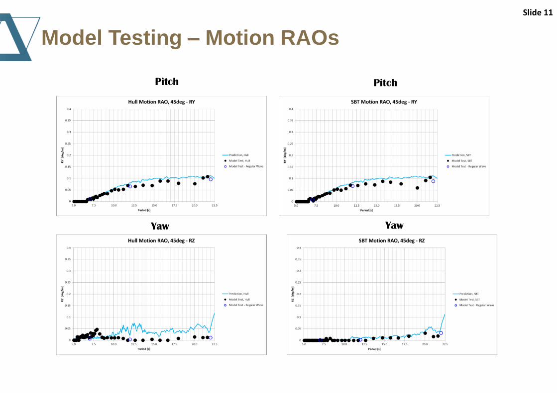
Model Testing – Motion RAOs
Slide 11
Pitch Pitch
Yaw Yaw
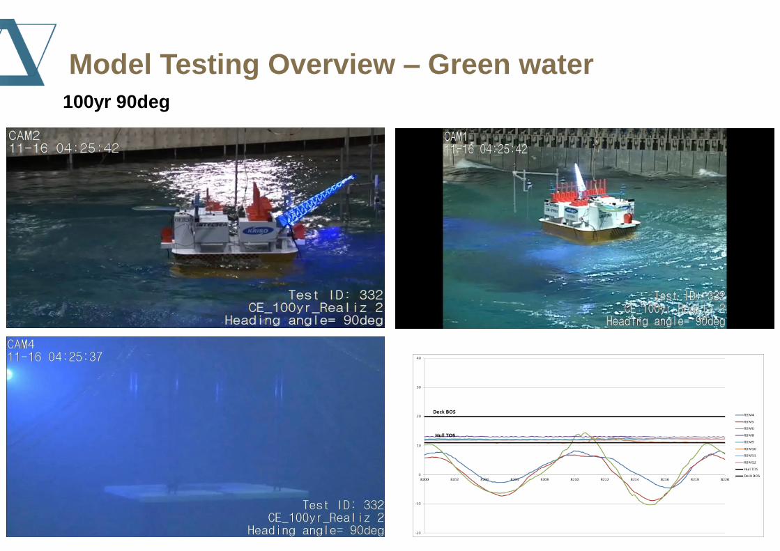
100yr 90deg
Model Testing Overview – Green water
LMF Fabrication, Transportation and Installation
Constructability of the SBT and Hull was reviewed and
confirmed by a major Korean shipyard
Optimum construction method: Modular fabrication and dry
dock assembly
Fabrication, transportation and installation sequence
Slide 13

LMF Fabrication, Transportation and Installation
Slide 14
SBT is fabricated in the dry dock
Hull is assembled on top of the SBT in the dry dock
Topside modules are integrated at quayside
The platform is wet-towed to installation site

LMF Fabrication, Transportation and Installation
Slide 15
8 of 16 Moorings and pre-laid
risers are installed
8 windlass/chains are
used to lower the SBT
Tendons upended
and installed

Slide 16
SCR Keel Haul

Slide 17
SCR Pull In

Tendon Lifting – Installation Options
Slide 18
Courtesy of www.jumboship.nl

Risks and Mitigation Measures
Fabrication :
Hull width may limit available fabrication facilities (dry docks)
Hull width may require crane with extra reach for lifting modules on the hull. Alternatively, skidding may be required
Additional fabrication supports needed for fabrication of SBT and Hull at one site
If SBT and Hull are fabricated separately, additional arrangement is required to install SBT under the Hull.
Offshore Installation :
Lowering SBT on mooring chains: Load equalization at each corner is provided and uneven load sharing between the groups is included;
Tendon installation : Installation risks (such as clashing) should be managed and weather window identified.
The system is storm safe at any installation step. Operations can be interrupted if necessary.
Slide 19

Technical and Economical Advantages
Elimination of turret
Use of SCRs + Simplified field layout
Elimination of wellhead platform (if used)
Slide 20
Economical Advantages
Extensive cost estimating performed for
FPSO applications around the world
More than 50% CAPEX savings could be
achieved on hull, mooring and risers in
the range of $500 – 1,000 Million
Main Technical Advantages
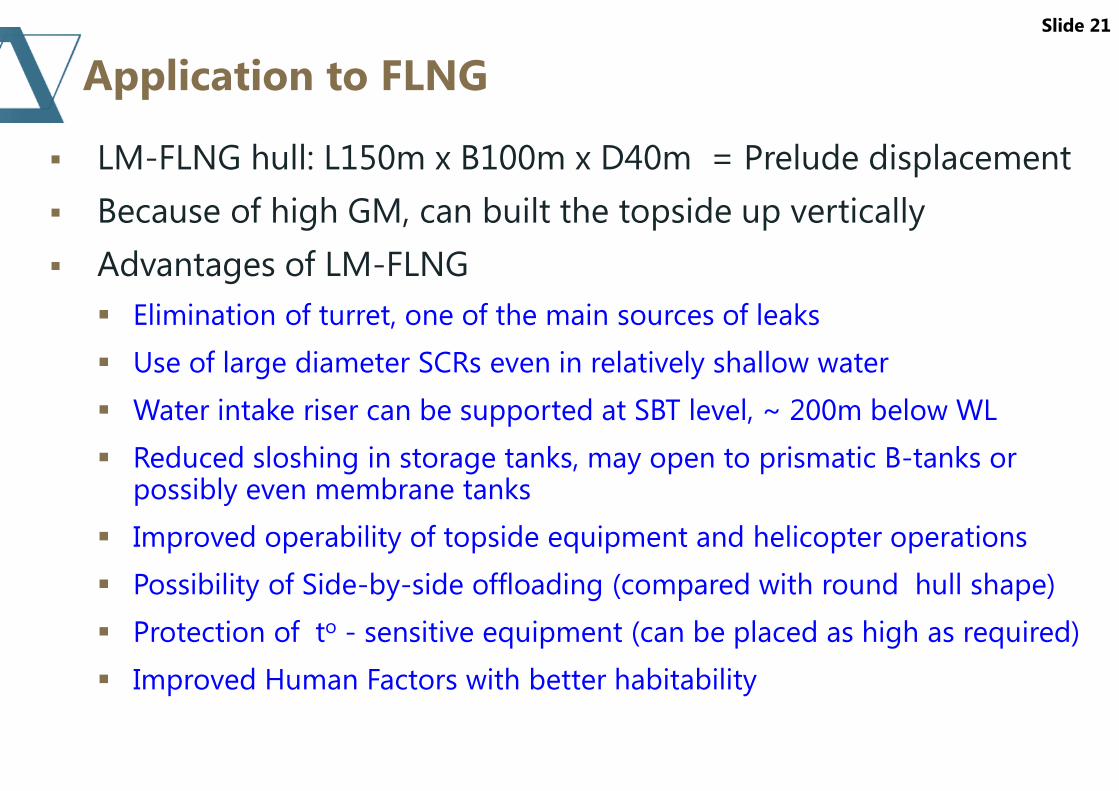
Application to FLNG
LM-FLNG hull: L150m x B100m x D40m = Prelude displacement
Because of high GM, can built the topside up vertically
Advantages of LM-FLNG
Elimination of turret, one of the main sources of leaks
Use of large diameter SCRs even in relatively shallow water
Water intake riser can be supported at SBT level, ~ 200m below WL
Reduced sloshing in storage tanks, may open to prismatic B-tanks or possibly even membrane tanks
Improved operability of topside equipment and helicopter operations
Possibility of Side-by-side offloading (compared with round hull shape)
Protection of to - sensitive equipment (can be placed as high as required)
Improved Human Factors with better habitability
Slide 21

Technology Status
Technical feasibility and economical advantage of the LMF has been studied and demonstrated
Constructability review was completed by a major Korean shipyard. No issues identified
Extensive model tests completed at KRISO in Nov. 2016 that confirmed the exceptional motion response
Risk workshop with major oil companies was completed in Feb. 2017; no show stoppers identified
Basic engineering package including a method of construction and installation was completed in Feb. 2017 and submitted to Class Society
Base case project execution plan is ready; various alternative options are being studied
E&P Special Meritorious Award for Engineering Innovation (at OTC 2017)
Approval in Principle granted by DNV-GL
Technology is project ready
Slide 22

Thank You!
Slide 23

DISCLAIMER
This presentation has been prepared by a representative of INTECSEA.
The presentation contains the professional and personal opinions of the presenter, which are given in good faith. As such, opinions presented herein may not always necessarily reflect the position of INTECSEA as a whole, its officers or executive.
Any forward-looking statements included in this presentation will involve subjective judgment and analysis and are subject to uncertainties, risks and contingencies—many of which are outside the control of, and may be unknown to, INTECSEA.
INTECSEA and all associated entities and representatives make no representation or warranty as to the accuracy, reliability or completeness of information in this document and do not take responsibility for updating any information or correcting any error or omission that may become apparent after this document has been issued.
To the extent permitted by law, INTECSEA and its officers, employees, related bodies and agents disclaim all liability—direct, indirect or consequential (and whether or not arising out of the negligence, default or lack of care of INTECSEA and/or any of its agents)—for any loss or damage suffered by a recipient or other persons arising out of, or in connection with, any use or reliance on this presentation or information.