the lock-in phenomenon in viv using a modified wake...
TRANSCRIPT

Keywords: lock-in; wake oscillator model; VIV; mass-damping ratio.
1. Introduction
Vortex-induced vibration occurs when shedding vortices (a Von Karman vortex street) exert oscillatory forces on a cylinder in the direction perpendicular to both flow and structure. The structure starts to oscillate due to these forces if it is not fixed. For fixed-cylinders, the vortex-shedding frequency is related to non-dimensional Strouhal number. The Strouhal number is defined as St=fvD/U, where fv is the predominant frequency of vortex shedding, U is the steady velocity of flow, and D is the diameter of the cylinder. The Strouhal number is found to be nearly constant with a value of 0.2 for a large range of Reynoldes numbers. This range is often called subcritical range of 300-2×10⁶ [1]. For flow past cylinders that are free to vibrate, the phenomenon of synchronization or lock-in is observed. For low flow speeds, the vortex-shedding frequency fv will be the same as that of a fixed cylinder. This frequency is fixed by Strouhal number. As the flow speed is increased, the shedding frequency approaches the vibration frequency of the cylinder fo. In this regime of flow speeds, the vortex-shedding * Corresponding author, Associate professor, Department of Mechanical Engineering Ferdowsi University of
Mashhad, Email: [email protected] † Graduate student, Department of Mechanical Engineering Ferdowsi University of Mashhad
A. Farshidianfar* Assistant Professor
H. Zanganeh†
Graduate student
The Lock-in Phenomenon in VIV Using A Modified Wake Oscillator Model for both High and Low Mass-Damping Ratio In the present paper the behavior of an elastically mounted cylinder in low and high mass-damping ratio is investigated. For high mass-damping ratio, a classical wake oscillator model is used. At the first, by neglecting all damping and nonlinear terms of this model, the possibility of using a linear model for determination of the lock-in range and the dominant mode is investigated. Then, without neglecting any terms, the nonlinear model is analyzed and the results are compared with experimental results. Due to change of the behavior of the system in low mass-damping ratio and disability of classic model in modeling of this change, a modified wake oscillator model is presented and the results of this model, in both low and high mass-damping ratio, are compared with experimental results.

Iranian Journal of Mechanical Engineering Vol. 10, No. 2, Sep 2009 6
frequency no longer follows the Strouhal relationship. Rather, the shedding frequency becomes “lock-in” to the oscillation frequency of the cylinder (i.e., fo≈fv ). If the vortex-shedding frequency is close to the natural frequency of the cylinder fn, as is often the case, the large body motions are observed within the lock-in regime (the structure undergoes near-resonance vibration). Vortex-Induced Vibrations are well-known phenomenon for engineers. Several kinds of structures subjected to wind or water currents may experience VIV such as tall buildings, chimneys, riser tubes bringing oil from seabed to the surface, airplane flaps (flutter), power transmission lines (galloping), stacks and long-span bridge. See Refs. [2-6] for studies focusing on the VIV of these structures. The length and higher flexibility of some of these structures further aggravate the problem. In offshore applications, VIV of slender structures such as pipelines, risers, tendons, and spar platforms challenge engineering designers. In these cases it has to be taken into account in their design as a potential cause of fatigue damage. Many empirical measurements have been done in VIV. Feng [7] in his experiment that was conducted in air showed that during lock-in regime, the frequency of vortex shedding and oscillation frequency of structure become equal. But in later works in low mass-damping ratio, Williamson and Khalak [8, 9] found new branch of response, they observed that during lock-in, the ratio of two frequencies wouldn’t remain equal to unit and these frequencies match with each other near other values like 1.4. Their studies showed that the behavior of frequencies changes in different mass-damping ratios. Different semi-empirical models have been used for describing VIV and lock-in phenomena such as wake oscillator model [10, 11, 12, 13], Sdof model that use a single ordinary differential equation to describe the behavior of structural oscillator [14, 15, 16], force-decomposition model that the lift force is decomposed into a fluid inertia force related to structure displacement and a fluid damping force related to structure velocity [17, 18], and variational approach [19, 20]. The coupling of fluctuating lift force and vibrating structure can be modeled by the simple concept of a wake oscillator. Such a model becomes really useful when computational limits arise for flow-field numerical simulations, particularly for 3-D domains with large aspect ratio and at high Reynolds numbers. Moreover, phenomenological models based on wake oscillators allow accessible analytical considerations and thus help the understanding of the physics of VIV. In such models the wake dynamics follow a van der Pol equation. In fact it is sufficient to have a self sustained oscillator with a limit cycle. The bluff body is then considered as another oscillator excited by the wake variable [21]. Conversely the effect of the solid motion on the wake is represented by a forcing on the van der Pol equation that can be proportional to displacement, velocity or acceleration of bluff body. Facchinetti et al. [22] have shown that the most appropriate forcing is proportional to the acceleration of the bluff body. The main focus of this paper is on the wake oscillator model, as a semi-empirical model, used to predict the response of the cylinder to the forces from the flow. This wake oscillator model coupled with a structure oscillator is found to describe most of the features of vortex-induced vibration phenomenology, such as lock-in domain. Both linear and nonlinear models are discussed in some detail, and the results of these models are compared with experimental results. Finally, because the behavior of system in low and high mass-damping ratio is different, a modified wake oscillator model is introduced and its results are compared with experimental results.

The Lock-in Phenomenon in VIV Using … 7
2. VIV model
In this section, for analyzing VIV, first, the model of structural oscillator will be described and then the dynamics of the wake oscillator will be explained. 2.1. Structural oscillator Let us consider a 1 dof system of a rigid cylinder of diameter D that is elastically mounted. This cylinder is constrained in such a way that can oscillate transversely to a uniform flow of free stream velocity U, Figure 1. The in plane displacement of cylinder Y, transversely to fluid flow, can be described by a linear oscillator
1
Where (.) means derivatives with respect to dimensional time T. the mass m consists of two parts; the mass of the structure ms and the fluid-added mass mf, which models the inviscid inertia effects of fluid [6], and reads
14 2
Where ρ is the fluid density, µ is dimensionless mass ratio and Cm=1 is the added mass coefficient [6]. In Eq. (1) the linear damping r models both viscous dissipations in support rs and fluid-added damping rf, namely
2
3
Where γ is a stall parameter and is a function of oscillation frequency, related to the mean sectional drag coefficient CD, γ=CD/4πSt, [4, 5]. St is Strouhal number.
In Eq. (1) the stiffness coefficient h only relates to external effects. Seeking simplicity we assume that γ is constant [23]. Developing a two dimensional model, all parameters of mass, damping and stiffness are defined per unit length. The fluid hydrodynamic effects on structure consist of two parts, the basic fluid effects, mf and rf, that directly influence structure oscillation by Eqs. (2) and (3), and the effects of vortices that is modeled as a forcing term S [22],
12 4
where CL is fluctuating lift coefficient. Defining structural angular frequency ,
structure reduced damping ξ / 2 and vortex-shedding frequency 2 / , Eq. (1) becomes
2 5

Iranian Journal of Mechanical Engineering Vol. 10, No. 2, Sep 2009 8
2.2. Wake oscillator The fluctuating nature of the vortex street is modeled by a nonlinear oscillator satisfying the van der Pol equation [24]
1 6
The dimensionless wake variable q that is related to the fluctuating lift coefficient, as for most of the models in the literature is considered as the main variable, can be defined as
2 / . Where CL(t) is instantaneous lift coefficient and CL0 is reference lift coefficient of a stationary cylinder under vortex shedding. The right hand side forcing term of Eq. (6), F, models the effect of cylinder motion on the wake dynamics. Researchers use different coupling models, such as displacement coupling, velocity coupling and acceleration coupling, to define this forcing term. In present paper an acceleration coupling, , will be used [22]. A and ε are the parameters which can be derived from experimental data on the wake dynamics, typically A=12 and ε=0.3 [22].
2.3. Coupling of wake and structural oscillator Introducing the dimensionless time t=ΩsT and space coordinate y=Y/D, Eqs. (5) and (6) lead to the coupled fluid-structure dynamical system
1 7
where / is the dimensionless frequency of a self-sustained oscillation of the wake, 2 / being the reduced velocity, the damping coefficient λ stands for all damping terms acting on the cylinder
2 8
and also / , that by considering the definition of q and S becomes
12
2 28 9
so
28
10
therefore Eq. (7) becomes
1 11

The Lock-in Phenomenon in VIV Using … 9
Overdots of these equations are derivatives with respect to dimensionless time t. In next sections we will seek the simple linear and complicated nonlinear solutions for these equations. 3. High mass-damping ratio 3.1. Linear model In order to analyzing the mechanism underlying the evolution of the frequency of the coupled system during the lock-in regime we will neglect some parts of Eq. (11). The only nonlinear term of these equations is that of van der Pol oscillator, . This term plays an important role on setting the amplitude of limit cycle of coupled system, but we assume that its effect on frequency is negligible. Similarly the negative damping term of van der Pol equation plays an important role on a self-excited amplification of the wake variable, but we neglect its effect too. Finally, the positive damping term of equation of motion of the cylinder, , also plays a role in the development of coupled dynamics, but not on the resulting frequency. Therefore because of typical range of values of the parameters ε and λ [22] it can be assumed that the effect of these three terms in evolution of frequency is negligible. Neglecting these three terms, Eq. (11) reduces to
, 12
Here, the two linear undamped oscillators are coupled in the same way of Eq. (11) so the only remaining control parameter is Ω which is proportional to flow velocity .
3.1.1. Coupled mode flutter The solution of Eq. (12) is straightforward. Assuming a harmonic motion with dimensionless amplitude of y0 and q0 and angular frequency of ω as , , the frequency equation becomes
1 1 0 13
We consider first the case that AM<1, as shown in Figure 2 for AM=0.5. In this case depending on the value of Ω, the system can neutrally be stable or unstable.
When √
or √
, two neutrally stable modes exist, which are defined,
respectively, by their real frequencies such that
2 1 1 1 1 4 14
these modes can be attributed to the wake dynamics, noted “W” in Figure 2 (a), or to structure dynamics, noted “S”. By considering their mode shape Eq. (12) yields:
1 15

Iranian Journal of Mechanical Engineering Vol. 10, No. 2, Sep 2009 10
so that the mode with the frequency closer to the line ωR=Ω in Figure 2 (a) is the wake mode and the mode closer to the line ωR=1 is the structure mode. In each mode, except at Ω=0, both components y and q exist, though one is clearly dominant.
In the range of √ √
two modes exist, but with complex conjugate
frequencies, such that
1 tan 1 16
where
12
4 1 1 1 1 17
This type of solution usually referred to as coupled mode flutter [5, 25], denoted by CMF in Figure 2 (a), which displays the merging of the two frequencies of the neutral modes, leading to a range of instability. One of these two modes is unstable (ωI<0), the other being damped, Figure 2 (b). Increasing Ω, a decoupling occurs and two neutral modes reappear. The phase between the lift q and the displacement y, Figure 2 (c), switches from 0 to π in this range of coupled-mode flutter. In this range no distinction can be made between a structure and a wake mode. A new regime arises, which a coupled mode with a phase shift allows a nonconservative cycle to exist, which is the cause of instability. The range of coupled-mode flutter may be considered as a range of lock-in because the frequency of the wake mode strongly deviates from the relation ω=Ω, and follow a relation where the natural frequency of the structure, ω=1, plays a role. Moreover, in this region an unstable mode appears, which will introduce dynamics different from that of the pure wake or structure mode.
The only parameter that influences the range of lock-in and the amplitude of the frequency deviation is the combined parameter of AM. In Figure 3 we vary its value from0.25 to 0.75. The extent of lock-in is found to increase steadily, mainly in its upper bound. The growth rate and damping of the modes, as well as the phase, are very similar to the case where AM=0.5.
3.1.2. Selection of the dominant mode It can be stated that the motion in y and q that emerge from any perturbation of the system is dominated by the unstable mode. Its oscillating frequency is given by the real part in Eq. (16)
1 tan 18
Outside the lock-in range we found that two neutral modes coexist. In the simplest model used in this paper these modes are neutrally stable because all damping terms, positive or

The Lock-in Phenomenon in VIV Using … 11
negative, have been neglected. In practice, due to unstable nature of wake, ε>0, and because of the damping of the motion of the structure, λ>0, each mode is either damped or unstable, and the motion will be dominated by the unstable mode. This can be investigated by taking into account the two damping terms, so that Eq. (7) becomes
19
where its frequency equation is
, , 1 0 20
The effect of parameters λ and ε on the modes of the system can be assessed by considering the variation of the eigenfrequencies ω with these parameters. Though they are of finite magnitude, typically λ=0.1 and ε=0.3, a simple first order expansion can be considered [26]
21
where ω0 satisfies the frequency equation without λ and ε, so that
, 0,0 0 22
The expansion of Eq. (20) reads
, , , 0,0 0 23
This implies that the sought variations ωλ and ωε satisfy, respectively
24
All derivatives being taken at the reference state (ω0, 0, 0). These derivatives can be easily derived from Eq. (20), so that the effect of two parameters λ and ε on the frequency ω is, at the first order λ, ε,
12 2
25
By considering the sign of the imaginary part of the frequency when ω0 is either the frequency of the wake mode or that of the structure mode, it appears that both parameters have a destabilizing effect on the wake mode and a damping effect on the structure mode. This is illustrated in Figure 4 where the effects of both parameters are shown independently, on the frequency and on the growth rate, using Eq. (25). In both cases the most unstable mode has the frequency of the wake mode outside the range of lock-in.
The resulting frequency of oscillation that can therefore be expected from such a system is shown in Figure 5, where only the dominant mode is shown. For small values of AM, lock-in is a small deviation of the evolution of the frequency of the original wake mode, in a limited

Iranian Journal of Mechanical Engineering Vol. 10, No. 2, Sep 2009 12
range of reduced velocity Ur. For large values of AM, a large range of Ur is affected even outside the range of coupled mode flutter.
3.2. Nonlinear model In the previous section, based on the linear model the damping and nonlinear terms have been neglected, but in this section these terms won’t be neglected. Therefore the effect of the nonlinear term of van der Pol equation, , will be considered in analysis. So that, the system of Eq. (11) will be analyzed in its complete form.
Seeking simplicity, first by a harmonic linearization method (see appendix), the van der Pol equation will be linearized again, but without neglecting any term. Using this method Eq. (11) becomes
4 1 26
Assuming the solution of the result system as
27
and substituting in Eq. (26) will give
1 28
4 1 29
Considering the Eqs. (28) and (29) and by using the relations of the phase φ and a simple algebra of complex numbers we will have
4 1
4 11
30
4 11
31
Substituting Eq. (31) in Eq. (30) and finding the van der Pol term in terms of the other parameters and substituting in Eq. (31) yields
1 1 32
The Lock-in Phenomenon in VIV Using … 13
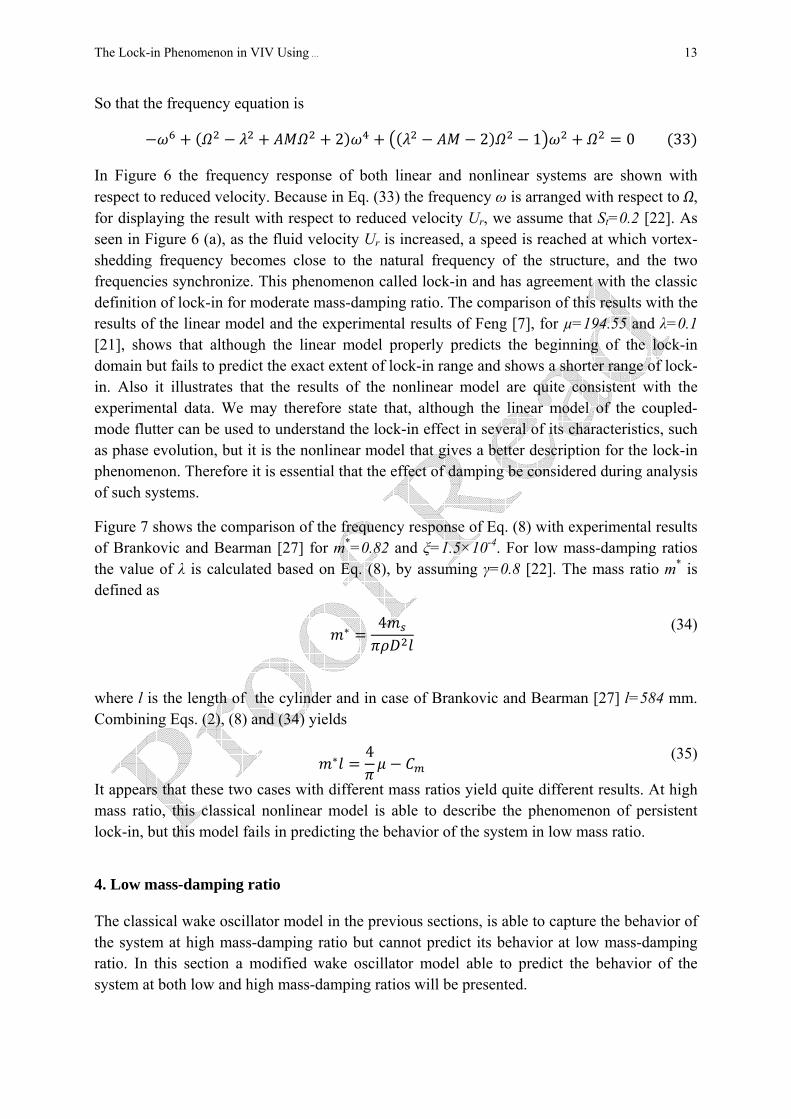
So that the frequency equation is
2 2 1 0 33
In Figure 6 the frequency response of both linear and nonlinear systems are shown with respect to reduced velocity. Because in Eq. (33) the frequency ω is arranged with respect to Ω, for displaying the result with respect to reduced velocity Ur, we assume that St=0.2 [22]. As seen in Figure 6 (a), as the fluid velocity Ur is increased, a speed is reached at which vortex-shedding frequency becomes close to the natural frequency of the structure, and the two frequencies synchronize. This phenomenon called lock-in and has agreement with the classic definition of lock-in for moderate mass-damping ratio. The comparison of this results with the results of the linear model and the experimental results of Feng [7], for µ=194.55 and λ=0.1 [21], shows that although the linear model properly predicts the beginning of the lock-in domain but fails to predict the exact extent of lock-in range and shows a shorter range of lock-in. Also it illustrates that the results of the nonlinear model are quite consistent with the experimental data. We may therefore state that, although the linear model of the coupled-mode flutter can be used to understand the lock-in effect in several of its characteristics, such as phase evolution, but it is the nonlinear model that gives a better description for the lock-in phenomenon. Therefore it is essential that the effect of damping be considered during analysis of such systems.
Figure 7 shows the comparison of the frequency response of Eq. (8) with experimental results of Brankovic and Bearman [27] for m*=0.82 and ξ=1.5×10⁻⁴. For low mass-damping ratios the value of λ is calculated based on Eq. (8), by assuming γ=0.8 [22]. The mass ratio m* is defined as
4 (34)
where l is the length of the cylinder and in case of Brankovic and Bearman [27] l=584 mm. Combining Eqs. (2), (8) and (34) yields
4 (35)
It appears that these two cases with different mass ratios yield quite different results. At high mass ratio, this classical nonlinear model is able to describe the phenomenon of persistent lock-in, but this model fails in predicting the behavior of the system in low mass ratio.
4. Low mass-damping ratio The classical wake oscillator model in the previous sections, is able to capture the behavior of the system at high mass-damping ratio but cannot predict its behavior at low mass-damping ratio. In this section a modified wake oscillator model able to predict the behavior of the system at both low and high mass-damping ratios will be presented.

Iranian Journal of Mechanical Engineering Vol. 10, No. 2, Sep 2009 14
4.1. VIV model It is believed that a model trying to accurately predict VIV must be able to describe the oscillations in which small oscillations fed energy into system and large oscillations remove it [28]. Also VIV is an inherently nonlinear and self regulated phenomenon [5]. These characteristics must be considered in every VIV model. In other engineering fields such as electrical engineering [29], biological and chemical structures [30] and laser dynamics [31] systems with similar characteristics can be found. For example, in the case of electrical engineering, the interaction of microwave oscillators is often referred to. Two important characteristics of these oscillators are negative resistance (which cause the amplitude of the oscillations to grow) and gain saturation (which limits the amplitude of the oscillation) [32]. In such systems the interaction of oscillators is modeled by two coupled van der Pol equations [33]. These observations can guide one to use two coupled van der Pol equations to model the VIV phenomenon, too. It means that not only the wake dynamics but also the structural oscillations can be modeled by van der Pol equation. The description of the structural oscillations by a van der Pol equation was used in before works of Teufel et al. [34]. They modeled two aerodynamically excited pendula by two coupled van der Pol equations. Although their model wasn’t a wake oscillator model but it showed the possibility of using a van der Pol equation for structural oscillations. As mentioned in previous sections, two equations of the system can be coupled via three different coupling terms, including acceleration, velocity and displacement coupling. In the present work, the velocity coupling is used for the modified model.
According to these assumptions, the equations of the system can be expressed as:
11
(36)
Where the parameters A and ε have the same values as their previous values, A=12 and ε=0.3, and the other parameters of these dimensionless equations are unchanged.
4.2. Frequency response By a harmonic linearization method, as we did for Eq. (11), the equation (36) will be linearized so that
4 1 4 1 37
By assuming φ=π/4 [22] and using similar process, as we did in section 2.3, the equation of angular frequency of ω will be
2 2 1 0 (38)
where 1 . The value of y0 is depended on the . So, for each the value of y0 is evaluated by solving equation (36) numerically, by a 4th order Rang-Kutta method for initial condition of q(0)=2.

The Lock-in Phenomenon in VIV Using … 15
Figures 8 (a) and (b) show the frequency response of the modified model for absolute value of ω. They show that the modified model has a good agreement with the experiment results. As seen, during lock-in, the frequency departs from unity and this behavior differs from what seen in figure 6 (a). This departure, experimentally, was shown in recent works [8, 9, 35 36]. As [9] believe, this new behavior is the result of imposing a low mass ratio.
Other branches of frequency response can occur under different conditions. For example, figure 9 shows the comparison of frequency response of the modified model and experimental results from a straked cylinder with m*=0.83, l=0.584 m and ξ=2.5×10⁻⁴ [27]. The strakes are 3-start with a pitch of five diameters and a height equal to 10% of the bare cylinder diameter. The mass ratio is defined as effective mass of the cylinder/displaced mass of water. Also, the reduced velocity Ur is calculated based on the diameter of bare cylinder.
Figure 10 shows the frequency response of the modified model at high values of the mass-damping ratio and Feng’s experimental results [7] for comparison. As seen in Figure 10, the new model also can precisely predict the behavior of system in high mass-damping ratio too.
5. Conclusion Vortex-induced vibration (VIV) can severely limit the operation of structures and may even lead to catastrophic failure. The behavior of structures during VIV is different in low and high mass-damping ratio. In first part of this paper, a classic wake oscillator model has been analyzed. By neglecting all damping and nonlinear terms, it has been shown that this linear model can be used for finding the lock-in range. But if we want to understand the real behavior of structure we should analyze the nonlinear model. So in continue, without neglecting any terms, the nonlinear model has been analyzed and the results have been compared with experimental results. This analysis showed that the classic wake oscillator model can precisely predict the behavior of system in high mass-damping ratio. Since the behavior of system in low mass-damping ratio is different and the classic model couldn’t predict this change, in next part of paper, a modified wake oscillator model has been proposed to investigate, analytically, vortex induced vibrations (VIV). The comparison of the results of the modified model with experimental results showed that this model can be used for both low and high mass-damping ratio. So this modified model can be used in designing of wide range of structures subjected to wind, air-flow and water such as bridges, tall buildings and offshore structures.
References [1] Chen, S.S., “Flow Induced Vibration of Circular Cylindrical Structures”, Hemisphere
Publishing Corporation, New York, (1987).
[2] Williamson, C.H.K., “Vortex Dynamics in the Cylinder Wake”, Annual Review of Fluid Mechanics, Vol. 28, pp. 477-539, (1996).
[3] Williamson, C.H.K., and Govardhan, R., “Vortex-Induced Vibration”, Annual Review
of Fluid Mechanics, Vol. 36, pp. 413-455, (2004).

Iranian Journal of Mechanical Engineering Vol. 10, No. 2, Sep 2009 16
[4] Williamson, C.H.K., and Govardhan, R., “A Brief Review of Recent Results in Vortex-Induced Vibrations”, Journal of Wind Engineering and Industrial Aerodynamics, Vol. 96, pp. 713-735, (2008).
[5] Sarpkaya, T., “A Critical Review of the Intrinsic Nature of Vortex-Induced Vibrations”,
Journal of Fluids and Structures, Vol. 19, pp. 389–447, (2004). [6] Blevins, R.D., “Flow-Induced Vibrations”, Van Nostrand Reinhold, New York, (1990). [7] Feng, C.C., “The Measurement of Vortex-Induced Effects in Flow Past a Stationary and
Oscillating Circular and D-section Cylinders”, Master's Thesis, University of British Columbia, Vancouver, (1968).
[8] Khalak, A., and Williamson, C.H.K., “Investigation of the Relative Effects of Mass and
Damping in Vortex-Induced Vibration of a Circular Cylinder”, Journal of Wind Engineering and Industrial Aerodynamics, Vol. 69-71, pp. 34-350, (1997).
[9] Khalak, A., and Williamson, C.H.K., “Motions, Forces and Mode Transitions in Vortex-
Induced Vibrations at Low Mass-Damping”, Journal of Fluids and Structures, Vol. 13, pp. 813–851, (1999).
[10] Bishop, R.E.D., and Hassan, A.Y., “The Lift and Drag Forces on a Circular Cylinder in
a Flowing Fluid”, Proceedings of the Royal Society Series, A. 277, pp. 32–50, (1963). [11] Hartlen, R.T., and Currie, I.G., “Lift-oscillator Model of Vortex-Induced Vibration”,
Journal of the Engineering Mechanics, Vol. 96, pp.577–591, (1970). [12] Skop, R.A., and Griffin, O.M., “A Model for the Vortex-Excited Resonant Response
of Bluff Cylinders”, Journal of Sound and Vibration, Vol. 27, pp. 225–233, (1973). [13] Griffin, O.M., Skop, R.A., and Koopman, G.H., “The Vortex-excited Resonant
Vibrations of Circular Cylinders”, Journal of Sound and Vibration, Vol. 31, pp. 235–249, (1973).
[14] Simiu, E., and Scanlan, R.H., “Wind Effects on Structures”, Wiley, New York, (1986). [15] Basu, R.I., and Vickery, B.J., “Across-wind Vibrations of Structures of Circular Cross-
Section—Part 2: Development of a Mathematical Model for Full-Scale Application”, Journal of Wind Engineering and Industrial Aerodynamics, Vol. 12, pp. 75–97, (1983).
[16] Goswami, I., and Scanlan, R.H., and Jones, N.P., “Vortex-Induced Vibration of
Circular Cylinders—Part 2: New Model”, Journal of Engineering Mechanics, Vol.119, pp. 2288–2302, (1993).
[17] Griffin, O.M., and Koopman, G.H., “The Vortex-excited Lift and Reaction Forces on
Resonantly Vibrating Cylinders”, Journal of Sound and Vibration, Vol. 54, pp. 435–448, (1997).
[18] Griffin, O.M., “Vortex-excited Cross-flow Vibrations of a Single Cylindrical Tube”,
Journal of Pressure Vessel Technology, Vol. 102, pp. 158–166, (1980).

The Lock-in Phenomenon in VIV Using … 17
[19]
Benaroya, H., and Wei, T., “Hamilton’s Principle for External Viscous Fluid–structure Interaction”, Journal of Sound and Vibration, Vol. 238, pp. 113–145, (2000).
[20] McIver, D.B., “Hamilton’s Principle for Systems of Changing Mass”, Journal of
Engineering Mechanics, Vol. 7, pp. 249–261, (1973). [21] de Langre, E., “Frequency Lock-In Is Caused By Coupled-mode Flutter”, Journal of
Fluids and Structures, Vol. 22, pp. 783-791, (2006). [22] Facchinetti, M.L., de Langre, E., and Biolley, F., “Coupling of Structure and Wake
Oscillators in Vortex-induced Vibrations”, Journal of Fluids and Structures, Vol. 19, pp.123–140, (2004).
[23] Balasubramanian, S., and Skop, R.A., “A New Twist on an Old Model for Vortex-
excited Vibrations”, Journal of Fluids and Structures, Vol. 11, pp. 395–412, (1997). [24] Nayfeh, A.H., “Introduction to Perturbation Techniques”, Wiley, New York, (1993). [25] Schmid, P.J., and de Langre, E. “Transient Growth before Coupled-mode Flutter”,
Journal of Applied Mechanics, Vol. 70, pp. 894–901, (2003). [26] Peake, N., “On the Behavior of a Fluid-Loaded Cylindrical Shell with Mean Flow”,
Journal of Fluid Mechanics, Vol. 338, pp. 347–410, (1997). [27] Branković, M., and Bearman, P.W., “Measurements of Transverse Forces on Circular
Cylinders Undergoing Vortex-induced Vibration”, Journal of Fluids and Structures, Vol. 22, pp. 829–836, (2006).
[28] Klamo, J.T., “Effects of Damping and Reynolds Number on Vortex-induced
Vibrations”, PhD Thesis, California Institute of Technology Pasadena, California, (2007).
[29] Lynch, J.J., “Analysis and Design of Systems of Coupled Microwave Oscillators”,
PhD Thesis, Department of Electrical and Computer Engineering, University of California at Santa Barbara, (1995).
[30] Mirollo, R.E., and Strogatz, S.H., “Synchronization of the Pulse-coupled Biological
Oscillators”, SIAM Journal of Applied Mathematics, Vol. 50, pp. 1645–62, (1990). [31] Wirkus, S., and Rand, R., “Dynamics of Two Coupled van der Pol Oscillators with
Delay Coupling”, Nonlinear Dynamics, Vol. 30, pp. 205–221, (2002). [32] Maas, S.A., “Nonlinear Microwave Circuits”, Artech House, Boston, (1988). [33] Wirkus, S., “The Dynamics of Two Coupled van der Pol Oscillators with Delay
Coupling”, PhD Thesis, Cornell University, Ithaca, (1999). [34] Teufel, A., Steindl, A., and Troger, H., “Synchronization of Two Flow Excited
Pendula”, Communications in Nonlinear Science and Numerical Simulation, Vol. 11, pp. 577–594, (2006).

Iranian Journal of Mechanical Engineering Vol. 10, No. 2, Sep 2009 18
[35]
Moe, G., and Wu, Z-J., “The Lift Force on a Cylinder Vibrating in a Current”, ASME Journal of Offshore Mechanics and Arctic Engineering, Vol. 112, pp. 297-303, (1990).
[36] Gharib, M. R., Leonard, A., Gharib, M. and Roshko, A. “The Absence of Lock-in and
the Role of Mass Ratio”, In Paper Proceedings Conference on Bluff Body Wakes and Vortex-induced vibrations, Washington D.C., 21-23 June (1998).
Nomenclature
A forcing term of wake oscillator
AM compound mass parameter
CL fluctuating lift coefficient
CL0 reference lift coefficient
Cm added mass coefficient
CMF coupled mode flutter
D diameter of the cylinder
fn natural frequency of the cylinder
fo vibration frequency of the cylinder
fv predominant frequency of vortex-shedding
M mass parameter
m total structure mass
mf fluid-added mass
ms structure mass
q wake dimensionless variable
q0 dimensionless amplitude of wake oscillator
r total damping of dimensional equation of structure
rf fluid-added damping
rs viscous dissipations in structure supports
S structure
S dimensional forcing term of structure equation
s dimensionless forcing term of structure equation
St Struohal number

The Lock-in Phenomenon in VIV Using … 19
T dimensional time
t dimensionless time
U fluid flow velocity
Ur fluid reduced velocity
Y dimensional displacement of cylinder
y dimensionless displacement of cylinder
y0 dimensionless amplitude of cylinder oscillations
W wake
Ω the ratio of vortex-shedding frequency and natural frequency of structure
Ωf angular frequency of vortex-shedding
Ωs natural frequency of structure
ω frequency response of system
ωI imaginary part of frequency response of system
ωR real part of frequency response of system
ωε system frequency response when the damping term of wake equation is considered
ωλ system frequency response when the damping term of solid equation is considered
γ stall parameter
ε parameter of van der Pol equation
λ total dimensionless damping of structure equation
µ mass ratio
ζ reduced damping of structure
ρ fluid density
φ phase between lift q and displacement
Appendix
Harmonic linearization method
This model not only can analyze weakly nonlinear problems but also can be used for strongly nonlinear problems. By solving a simple nonlinear equation, this model will be described in below.
Consider the below Duffing's equation:

Iranian Journal of Mechanical Engineering Vol. 10, No. 2, Sep 2009 20
, 0 0 39
The physical insight leads us to the response of , that satisfy the initial condition. therefore
cos – cos cos 4 3 cos cos 3
cos 13
4 4 cos 3 40
Neglecting the third harmonic terms give
cos 1 1 41
So that the Eq. (39) becomes
13
4 0 42
Therefore by assuming response of the system as we will have
13
4
cos 13
4 43
This response is as the response that obtain from other methods like The methods of Poincare and Lindstedt or methods of Krylov and Bogoliubov.

The Lock-in Phenomenon in VIV Using … 21
Figures
Figure 1. Model of coupled structure and wake oscillator for 2-D vortex-induced vibration.
h
r
X
Y
Z
q
U

Iranian Journal of Mechanical Engineering Vol. 10, No. 2, Sep 2009 22
Figure 2. Effect of the dimensionless flow velocity Ω on the modes of the coupled system defined by Eq. (12), for AM=0.5: (a) frequency, (b) growth rate (c) phase between the lift q and the displacement
y. -, unstable mode; -, damped mode; -.-, limit of the lock-in range; …, wake mode of uncoupled solution when AM=0. In (a), S denotes a structure mode, W denotes a wake mode and CMF is a
coupled-mode flutter solution.
ωR
Ω
Ω
Ω
-ωR/ωI
φ/π
(a)
(b)
(c)
W
W
S
S
CMF

The Lock-in Phenomenon in VIV Using … 23
Figure 3. Influence of the combined mass parameter AM on the characteristics of lock-in: (a) frequency, (b) growth rate, (c) phase between the lift q and the displacement y. In each plot the results for three values of AM are shown, 0.25, 0.50 and 0.75. -, unstable mode; -, damped mode; -.-, …, wake
mode of the uncoupled solution when AM=0.
Ω
Ω
Ω
ωR
-ωR/ωI
φ/π
(a)
(b)
(c)

Iranian Journal of Mechanical Engineering Vol. 10, No. 2, Sep 2009 24
Figure 4. Selection of the dominant mode by the effect of damping on the growth rate of the modes of the coupled system, AM=0.50, using Eq. (25). (a) and (b) effect of the negative damping of the wake
equation, ε=0.3 and λ=0; (c) and (d) effect of the damping of the cylinder, ε=0 and λ=0.1, respectively. In (a) and (c) the frequency of the most unstable mode is shown in bold lines,
correspondingly to the highest growth rate in (b) and (d), respectively.
ωR ωR
-ωR/ωI -ωR/ωI
Ω Ω
Ω Ω
(a) (c)
(b) (d)

The Lock-in Phenomenon in VIV Using … 25
Figure 5. Effect of the flow velocity Ω on the frequency of the dominant mode of the coupled system. (a) AM=0.05, the frequency deviates from Strouhal law only near Ω=1, by coupled mode flutter.
AM=0.75 the frequency deviates from Strouhal law in a large range of coupled mode flutter, and also is affected outside this range. -, frequency; …, uncoupled solution; W, wake mode; CMF, coupled
mode flutter.
W
W
CMF
Ω
ωR
(a)
(b)

Iranian Journal of Mechanical Engineering Vol. 10, No. 2, Sep 2009 26
Figure 6. Comparison of frequency response of classic wake oscillator model with the result of the linear model and the experimental result of Feng [7].

The Lock-in Phenomenon in VIV Using … 27
Figure 7: Frequency response of the classical model for low mass-damping ratio (µ=1.1615, ξ=1.5×10⁻⁴). –,the classical wake oscillator model; , Branković and Bearman’s experimental
results [27].

Iranian Journal of Mechanical Engineering Vol. 10, No. 2, Sep 2009 28
Figure 8: Frequency respose of the modified model for low mass-damping ratio. (a) , modified model; , experimental data of Williamson and Khakak [9] for m*=3.3, l=0.381 m
and ξ=0.0026 (µ=1.773). (b) , modified model; , experimental data of Brankovic and Bearman [27] for m*=0.82, l=0.584 m and ξ=1.5×10⁻⁴ (µ=1.1615).

The Lock-in Phenomenon in VIV Using … 29
Figure 9: Frequency respose of the modified model for low mass-damping ratio. , modified model; , experimental data of Brankovic and Bearman [27] for m*=0.83, l=0.584 m and
ξ=2.5×10⁻⁴ (µ=1.1661).
Figure 10: Frequency respose of the modified model for high mass-damping ratio. , modified model; , experimental data of Feng [7] (µ=194.55 and λ=0.1 [21]).

Iranian Journal of Mechanical Engineering Vol. 10, No. 2, Sep 2009 30
دهيچكال قرار دارد، يان سيشود و در معرض جريم يك نگهداريك استوانه كه به صورت االستين مقاله رفتار يدر ا
باال از مدل گردابه ييرايم - جرم يهانسبت يبرا .شوديم ين بررسييباال و پا ييرايم -جرم يهادر نسبتان ن مدل، امكيا يرخطيو غ ييرايم يهانخست با صرف نظر كردن از ترم. ميكنيك استفاده مينوسانگر كالس
ين مود غالب، بررسييو تع lock-inن بازه وقوع ييچون تع يموارد يبرا يك مدل ساده و خطياستفاده از ج حاصل از يكرده و نتا يرا بررس يرخطيمذكور مدل غ يهادر ادامه بدون صرف نظر كردن از ترم. شوديم
ييرايم - جرم يهاستم در نسبتير رفتار سييت با توجه به تغيدر نها. ميكنيسه ميمقا يج تجربيرا با نتاآن شود و يم يمعرف ياشده ردابه نوسانگر اصالحگن رفتار، مدل يا ينيبشيك در پيمدل كالس ين، و ناتوانييپا . سه خواهد شديمقا يج تجربين، با نتاييباال و پا ييرايم - جرم يهانسبت ين مدل برايج حاصل از اينتا