the interaction of corrosion and fatigue in aircraft ... · masaag paper 118 . military aircraft...
TRANSCRIPT
MASAAG Paper 118
Military Aircraft Structures Airworthiness Advisory Group
Paper 118
The Interaction of Corrosion and Fatigue in Aircraft Structures
Dr K Brown QinetiQ
22 August 2012
ii MASAAG Paper 118
DISTRIBUTION
Task Sponsor Dr Steve Reed, Dstl
MASAAG Members
See MASAAG Distribution at time of paper release
Authorship Panel
Dr D L Bartlett, QinetiQ Dr E A Birt, QinetiQ Dr A Kaddour, QinetiQ Dr R S Oakley, QinetiQ Paper Closure Statement
A draft version of MASAAG Paper 118 was circulated to all MASAAG Members for comment on 11 September 2012. The MASAAG agreed that the paper provided a valuable summary on the interaction effects of corrosion and fatigue in aircraft structures. However, it was agreed at the 74th MASAAG that appropriate measures were in place to assure structural integrity under such
This threats and that no further action was considered necessary by the MASAAG at this time. closure statement was endorsed by the 75th MASAAG on 10 September 2013.
MASAAG Paper 118 iii
EXECUTIVE SUMMARY
Corrosion and fatigue present risks to aircraft structural integrity and can lead to increased
aircraft life cycle costs and reduced aircraft availability. The two processes can interact in a
variety of ways, such as the nucleation and growth of fatigue cracks from corrosion damage.
These interactions can accelerate markedly the development of damage in the aircraft structure.
However, corrosion, fatigue and their interactions can be very sensitive to a wide range of
factors, such as material type, structural configuration, load spectra and environment, so that
prediction of the damage growth can be difficult.
The traditional UK Ministry of Defence (MoD) approach to the management of structural integrity
corrosion risks in service has been a ‘find-and-fix’ approach. This assumes that corrosion is
detected by inspections and removed from the structure or system, with an assessment of the
integrity and life of the structure or component being made based upon the remaining material.
However, there is evidence from Ageing Aircraft Audits (AAA) that corrosion is not always
removed from the aircraft and it is also reasonable to assume that there are a significant
number of unknown corrosion locations on aircraft across the fleets. There is at present
insufficient relevant information available to MoD Duty Holders and the Military Airworthiness
Authority (MAA) as to the likely implications of continued operations with such corrosion present.
An extensive literature review has therefore been undertaken to identify the current
understanding internationally of corrosion-fatigue interactions in aircraft structure. The findings
from the review are presented in this paper.
A generalised corrosion-fatigue process may be broken down into a number of stages. This can
aid in developing prediction methods and in assessing the suitability of different approaches to
the individual stages. The methods to be used for each stage will depend upon the physical
situation and the available approaches. Established approaches and available software should
be used as far as possible for the prediction of corrosion-fatigue interactions, as this will
minimise time and effort and should increase confidence in the outputs.
An initial assessment has been made of available software for corrosion and fatigue prediction
to assess their use in the prediction of potential corrosion-fatigue interactions such as the
growth of fatigue cracks from corrosion damage. The corrosion prediction software can address
galvanic and pitting corrosion, but further assessment is required of its potential to predict the
evolution of those parameters (e.g. pit dimensions) which could influence the development of
fatigue cracks from the corrosion. Existing fatigue and fracture software has been used to model
the growth of a fatigue crack from an initial flaw related to the corrosion damage. It may be
necessary to combine a finite element package for calculation of the stresses in a structural
iv MASAAG Paper 118
feature, a corrosion prediction model to assess the growth of corrosion pits, and a fatigue and
fracture code to predict the fatigue crack growth from the corrosion pits through to final fracture.
There are a number of structurally significant corrosion types but the most important are
probably general attack, pitting corrosion and exfoliation corrosion. The effects of other
corrosion types such as crevice corrosion upon fatigue behaviour may be modelled by similar
approaches to these three types. Corrosion features which will influence fatigue behaviour
include thickness loss (increased stress levels and/or reduced stiffness), corrosion pits (stress
concentrations) and corrosion products (changed materials properties and/or stress state).
Fatigue crack growth prediction is in general more advanced than corrosion prediction. The
most immediate benefits from the prediction of corrosion-fatigue interactions may thus be
realised by improving the accuracy of prediction of fatigue crack growth from corrosion damage
and of corrosion fatigue. Such improvements might also allow accurate back-calculation from
the required fatigue lives to determine acceptable levels of corrosion in the structure (e.g.
corrosion pit dimensions). The effects of corrosion upon fatigue behaviour under aircraft
spectrum loading may be different to those for the constant amplitude loading used in much
previous work. It may be possible to adapt existing fatigue and fracture software to allow for the
effects of corrosion by using suitably modified static material properties and fatigue behaviour.
However, consideration needs to be given to the applicability of material data obtained in the
laboratory to actual service conditions.
NDE methods can provide detailed measurements of corrosion damage, such as the
dimensions of corrosion pits, which can provide inputs to fatigue crack growth software.
However, the time and effort required for NDE inspection and fatigue analysis may mean that
the use of such detailed data is only practicable for relatively small areas of structure which are
of particular concern. Data fusion is the combination of a number of NDE techniques which
should potentially allow more rapid scanning to determine the corrosion state of a structure and
so could be a practical means of providing suitable inputs to fatigue models.
Data from the maintenance effort required to repair corrosion damage (examples of which are
given in an appendix) may be used for the prediction of corrosion in an aircraft structure. This
approach has the advantage that the data are obtained for real structures and actual service
environments. However, the processes for the recording and analysis of the data must be
carefully designed to accurately provide the relevant quantitative information without excessive
additional effort on the part of the maintenance organisation. It is recommended that the
feasibility of such an approach should be investigated.

MASAAG Paper 118 v
AUTHORSHIP
Principal Author: Dr K Brown, QinetiQ Authorship Panel: Dr D L Bartlett, QinetiQ Dr E A Birt, QinetiQ Dr A Kaddour, QinetiQ Dr R S Oakley, QinetiQ

vi MASAAG Paper 118
TABLE OF CONTENTS
Distribution ..................................................................................................................................... ii Executive Summary ...................................................................................................................... iii Authorship ...................................................................................................................................... v Table of Contents ......................................................................................................................... vi Abbreviations ............................................................................................................................... viii
1 INTRODUCTION .................................................................................................................... 1
2 CORROSION-FATIGUE INTERACTIONS ............................................................................ 3
2.1 The Interaction of Corrosion and Fatigue ................................................................ 3
2.2 Factors Affecting Corrosion and Fatigue ................................................................. 4
2.2.1 Aircraft Age and Environment/Fatigue History ......................................................... 4
2.2.2 Structural Material Type ........................................................................................... 4
2.2.3 Corrosion Type ........................................................................................................ 4
2.2.4 Operating Environment ............................................................................................ 5
2.2.5 Structural Design ..................................................................................................... 5
2.2.6 Fatigue Loading Spectra .......................................................................................... 6
2.2.7 Corrosion Protection Schemes ................................................................................ 6
2.2.8 Maintenance and Repair .......................................................................................... 6
2.3 Modelling Approaches ............................................................................................. 7
2.4 Preliminary Software Assessment ........................................................................... 8
2.4.1 Corrosion Prediction Software ................................................................................. 9
2.4.2 Fatigue and Fracture Software .............................................................................. 10
2.4.3 Prediction of Corrosion and Fatigue ...................................................................... 11
2.4.4 Probabilistic Approaches ....................................................................................... 11
MASAAG Paper 118 vii
3 CORROSION AND FATIGUE CRACK INITIATION ........................................................... 12
3.1 Structurally Significant Corrosion Types ............................................................... 12
3.1.1 General Attack ....................................................................................................... 12
3.1.2 Pitting Corrosion .................................................................................................... 12
3.1.3 Intergranular and Exfoliation Corrosion ................................................................. 12
3.1.4 Galvanic and Crevice Corrosion ............................................................................ 13
3.1.5 Environmentally-Assisted Cracking and Fretting Fatigue ..................................... 13
3.2 Corrosion Prediction .............................................................................................. 14
3.3 Initiation of Fatigue Cracks from Corrosion ........................................................... 15
3.4 NDE Corrosion Parameters ................................................................................... 16
3.5 Maintenance and Other Data ................................................................................ 17
4 FATIGUE CRACK GROWTH .............................................................................................. 19
4.1 Fatigue Crack Growth from Corrosion................................................................... 19
4.2 Spectrum Loading and Environment ..................................................................... 20
5 CONCLUSIONS .................................................................................................................. 22
6 RECOMMENDATIONS ....................................................................................................... 24
6.1 General considerations ......................................................................................... 24
6.2 Prediction of Corrosion-Fatigue Interactions ......................................................... 24
References .................................................................................................................................. 25 APPENDIX A: CORROSION COSTS FOR USAF AND RAF AIRCRAFT TYPES ................................... 29 Report Documentation Form ....................................................................................................... 34

viii MASAAG Paper 118
ABBREVIATIONS
AAA Ageing Aircraft Audit
CFRP Carbon Fibre Reinforced Plastic
EAC Environmentally-Assisted Cracking
ISTAR Intelligence, Surveillance, Targeting And Reconnaisance
MAA Military Airworthiness Authority (United Kingdom)
MoD Ministry of Defence (United Kingdom)
NDE Non-Destructive Evaluation
RA (MAA) Regulatory Article
RAAF Royal Australian Air Force
RAF Royal Air Force (United Kingdom)
SCC Stress Corrosion Cracking
S-N Stress-life (fatigue data)
USAF United States Air Force
WLIM White-Light Interference Microscopy

MASAAG Paper 118 ix
Intentionally Blank

MASAAG Paper 118 1
1 INTRODUCTION
Corrosion and fatigue present risks to aircraft structural integrity and can lead to increased
aircraft life cycle costs and reduced aircraft availability (e.g. Hertzberg 2009). An analysis of
aircraft structural failures (Findlay and Harrison 2002) found that 55% were due to fatigue, 16%
to corrosion and 7% to environmentally-assisted cracking (EAC). Although these data indicate
that fatigue represents a greater threat to structural integrity than corrosion, corrosion results in
greater life cycle costs than fatigue (ibid). As an indication of magnitude, the cost of corrosion to
the United States Air Force (USAF) was over $1 billion in 2001 (Benavides 2009). Some
examples of corrosion costs for individual aircraft types are included in Appendix A. As the
corrosion costs are primarily due to inspection and maintenance (e.g. Kinzie 2005), corrosion is
also likely to give a greater reduction in aircraft availability than fatigue.
Whilst Harrison and Findlay (2002) identified the truly synergistic EAC processes as one group,
corrosion and fatigue can also interact in other ways, e.g. it was stated that some of the fatigue
failures in the survey may have initiated at stress concentrations produced by corrosion. Fatigue
cracking had developed from corrosion pits in the F/A-18 trailing edge flap hinge lug (Clark
2010) and from stress corrosion cracking (SCC) in the C-5A aft crown (Ball et al 2010). A civil
Taylorcraft BF12 floatplane was lost in 2007 as a result of the fracture of a wing bracing strut
due to extensive corrosion followed by fatigue cracking (NTSB 2008). In December 2008 the
Russian MiG-29 fleet was grounded following the loss of two aircraft to corrosion-induced
fatigue failure of the vertical tail surfaces (Jane’s 2011). Mig-29 vertical tail surfaces have
carbon fibre reinforced plastic (CFRP) skins (Dragan et al 2005), showing that corrosion-fatigue
interactions are not restricted to all-metal structures.
The interaction of corrosion and fatigue can accelerate markedly the development of damage in
the aircraft structure, e.g. full-scale CF-18 fuselage fatigue tests showed a reduction in the
fatigue life of an upper outboard longeron by a factor of four when corrosion was present
(Bellinger and Liao 2009). However, corrosion, fatigue and their interactions can be very
sensitive to a wide range of factors, such as material type, structural configuration, load spectra
and environment, so that prediction of the damage growth can be difficult.
The UK Ministry of Defence (MoD) policy and regulation for the management of structural
integrity corrosion risks in service has relied upon a ‘find-and-fix’ approach. This assumes that
corrosion is detected by inspections and removed from the structure or system. An assessment
of the integrity and life of the structure or component is then made based upon the material
remaining. However, evidence from Ageing Aircraft Audits (AAA) suggests that there are an
increasing number of incidents across the MoD fleets where corrosion is not being removed
2 MASAAG Paper 118
from aircraft. It is also reasonable to assume that there are a significant number of unknown
corrosion locations on aircraft across the fleets. It is essential that best advice can be provided
to MoD Duty Holders and the Military Airworthiness Authority (MAA) as to the likely implications
of continued operations with such corrosion present, e.g. the possible nucleation and growth of
fatigue cracks from the corrosion damage. Such advice would be applicable to, for example,
Structural Examination Programmes (MAA RA 5720, Paragraph 60), Ageing Aircraft Audits
(MAA RA 5723, Paragraph 9a) and Life Extension Programmes (MAA RA 5724, Paragraph 21).
It is not currently possible to provide this advice as there is insufficient relevant information
available on the potential interactions of corrosion and fatigue in aircraft structures in the service
environment.
An extensive literature review has therefore been undertaken to identify the current
understanding internationally of corrosion-fatigue interactions in aircraft structure. This has
included current approaches to, and understanding of, corrosion prediction, the effects of
corrosion on crack nucleation and the growth of fatigue cracks under realistic loading spectra
and environmental conditions. An initial assessment has also been made of available software
packages for corrosion and fatigue prediction.
The results of the literature review are presented in this report. Section 2 provides a general
overview of corrosion-fatigue interactions. Section 3 considers the development and prediction
of corrosion and the potential initiation of fatigue cracks from the corrosion damage. Section 4
discusses the prediction of fatigue crack growth in the presence of corrosion and under realistic
loading spectra. Conclusions are presented in Section 5 and recommendations in Section 6.
Some corrosion costs for USAF and RAF aircraft types are provided and discussed in Appendix
A.
MASAAG Paper 118 3
2 CORROSION-FATIGUE INTERACTIONS
2.1 THE INTERACTION OF CORROSION AND FATIGUE
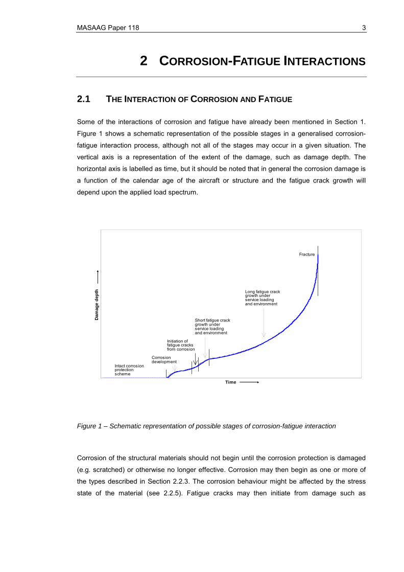
Some of the interactions of corrosion and fatigue have already been mentioned in Section 1.
Figure 1 shows a schematic representation of the possible stages in a generalised corrosion-
fatigue interaction process, although not all of the stages may occur in a given situation. The
vertical axis is a representation of the extent of the damage, such as damage depth. The
horizontal axis is labelled as time, but it should be noted that in general the corrosion damage is
a function of the calendar age of the aircraft or structure and the fatigue crack growth will
depend upon the applied load spectrum.
Intact corrosionprotectionscheme
Corrosiondevelopment
Initiation offatigue cracksfrom corrosion
Short fatigue crackgrowth underservice loadingand environment
Long fatigue crackgrowth underservice loadingand environment
Fracture
Time
Dam
age
dept
h
Figure 1 – Schematic representation of possible stages of corrosion-fatigue interaction
Corrosion of the structural materials should not begin until the corrosion protection is damaged
(e.g. scratched) or otherwise no longer effective. Corrosion may then begin as one or more of
the types described in Section 2.2.3. The corrosion behaviour might be affected by the stress
state of the material (see 2.2.5). Fatigue cracks may then initiate from damage such as

4 MASAAG Paper 118
corrosion pits, as considered in Section 3.3. These fatigue cracks – or others which nucleated at
stress concentration features such as fastener holes – may then develop through short and long
fatigue crack growth stages to final fracture. This fatigue crack growth may be subjected to a
corrosive environment in addition to spectrum fatigue loading and this may modify the fatigue
and fracture behaviour, e.g. by the introduction of EAC mechanisms.
2.2 FACTORS AFFECTING CORROSION AND FATIGUE
The interaction of corrosion and fatigue is influenced by a variety of factors and some of these
are considered below. Some further discussion of factors affecting corrosion is also included as
part of Appendix A.
2.2.1 AIRCRAFT AGE AND ENVIRONMENT/FATIGUE HISTORY
As shown schematically in Figure 1, corrosion/fatigue damage will develop with time and the
number of fatigue cycles. The precise combination of the applied environment and fatigue
loading must however be considered when determining the potential for corrosion-fatigue
interactions. As an example, an aircraft might be subjected to alternate periods of high
temperatures (over 50°C) and high humidity on the ground in a tropical environment, tending to
promote corrosion, and fatigue loading at low temperatures in flight at altitude, tending to cause
fatigue cracking. The potential corrosion-fatigue interactions might then depend principally upon
factors such as the time spent on the ground and the fatigue spectrum in flight.
2.2.2 STRUCTURAL MATERIAL TYPE
The type of material in the aircraft structure can have a major effect on the extent and type of
corrosion, fatigue and their interactions. Investigations of corrosion-fatigue interactions for
aircraft structural applications have included aluminium alloys such as 2024-T3 (e.g. van der
Walde and Hilberry 2008) and 7075-T6 (e.g. Smith et al 2001, Harlow & Wei 2009, Burns et al
2011), and steels such as D6AC (Mills et al 2002) and AF1410 (Rusk et al 2009). There has
also been much work on corrosion fatigue of steels for marine and offshore applications (e.g.
Coudert and Renaudin 1998) and some of the approaches developed could be potentially
relevant to aircraft structures.
2.2.3 CORROSION TYPE
Corrosion types which could potentially be involved in corrosion-fatigue interactions in aircraft
structures are described in more detail in Section 3.2. General attack, pitting corrosion and
MASAAG Paper 118 5
exfoliation corrosion are probably the most structurally significant forms of corrosion attack (Mills
et al 2009). These forms may occur together in an aircraft structure, such as general attack and
pitting corrosion. Other types of corrosion may arise from different mechanisms (e.g. galvanic or
crevice corrosion), but the resultant damage morphology is generally typical of general attack,
pitting corrosion and/or exfoliation corrosion (ibid). This suggests that these other types of
corrosion may be able to be treated similarly to the three most significant types in terms of, for
example, the growth of cracks from corrosion pits. The different corrosion mechanisms would
however need to be allowed for in assessing when the corrosion would be sufficiently advanced
to lead to the nucleation of fatigue cracks.
2.2.4 OPERATING ENVIRONMENT
Corrosion can vary widely depending upon the applied environment, e.g. it is generally more
prevalent in a maritime than a terrestrial environment. As an example, Sun et al (2009) reported
marked differences between coastal, urban and industrial environments for the corrosion of
2024 and 7075 aluminium alloys exposed to the atmosphere for twenty years. The geographical
locations in which an aircraft operates can thus have significant influences on the development
of corrosion and on potential corrosion-fatigue interactions. The recording of the geographical
bases and deployment of aircraft is therefore used by aircraft operators such as the USAF
(Young and Blair 2011) and Royal Australian Air Force (RAAF) (Trathen 2012) to aid in the
prediction of corrosion development in their aircraft.
2.2.5 STRUCTURAL DESIGN
The aircraft structural design can influence the corrosion and fatigue behaviour, e.g. fatigue
cracking and corrosive behaviour at a fastener hole can depend on the materials and geometry
of the joint (Gaydos 2011). A fuselage lap joint may develop multiple fatigue cracks at the
fastener holes as the aircraft approaches or exceeds the design life (Eastaugh et al 1999),
whilst crevice corrosion might occur in the lap joint and be accelerated because of the occluded
environment (Mills et al 2009). The stress distribution in the structural configuration – possibly
including residual stresses, such as at a cold-expanded fastener hole – may also influence the
nature of the corrosion-fatigue interactions, e.g. stress corrosion cracking requires a tensile
stress in the material (Mills et al 2009). Whether a crack initiates at a corrosion pit or a structural
feature such as a fastener hole will in general depend upon the relative stress levels at the two
locations. Joining processes such as welding may introduce changes in material properties and
residual stresses in the structure, although Ghidini et al (2005) reported that corrosion prior to
fatigue gave similar reductions in stress-life (S-N) fatigue behaviour in friction-stir welded 2024-
T3 aluminium alloy and the parent material when the weld residual stresses were low.
6 MASAAG Paper 118
2.2.6 FATIGUE LOADING SPECTRA
Aircraft loading spectra may be dominated by, for example, manoeuvre loads (combat aircraft
wings), gust loads (transport aircraft wings), fuselage pressurisation (transport aircraft) or
structural vibration (helicopters). The nature of the applied loading influences fatigue crack
initiation and growth but it might also influence the potential corrosion-fatigue interactions, for
example if overloads in the spectrum change the fatigue crack opening. The effect of realistic
spectrum loading on potential corrosion-fatigue interactions should therefore be addressed.
The effect of the loading frequency on the potential corrosion-fatigue interactions should also be
considered. As an example, the moisture ingress into a fatigue crack which is open in each load
cycle, and hence the potential for corrosion, may be greater, per cycle, at a lower frequency (as
in service) than at a higher frequency (as in laboratory tests).
2.2.7 CORROSION PROTECTION SCHEMES
For many aerospace materials such as high-strength aluminium alloys, the time for corrosion to
develop to the critical pit size for fatigue cracking is relatively short and the rate determining step
is the time for the corrosion protection scheme – e.g. anodising, paint and/or corrosion
protection compounds – to fail at imperfections or damage sites. Failure models for the
corrosion protection systems are therefore included in software for corrosion prediction (see
Section 3.2).
The effect of corrosion protection schemes applied to the structure may need to be considered
for prediction of the fatigue behaviour of the structure. Jaya et al (2010), for example, reported
that the presence of corrosion inhibiting compounds had a significant influence on the fatigue
life of riveted 2024-T3 aluminium alloy joints, and also on the failure mode of the joints.
Anodising might also contribute to a reduction in fatigue performance by promoting earlier crack
initiation as a result of the presence of the oxide layer.
2.2.8 MAINTENANCE AND REPAIR
The effects of maintenance and repair should be considered when assessing potential
corrosion-fatigue interactions. Maintenance, repair and refurbishment activities which, for
example, remove corrosion and fatigue damage or restore corrosion protection schemes should
accordingly reduce the potential for corrosion-fatigue interactions (see Appendix A). Repairs
might, however, modify behaviour such as moisture ingress to a structure or could introduce
new stress concentrations (e.g. at fasteners) and this will also need to be considered.
MASAAG Paper 118 7
2.3 MODELLING APPROACHES
The breaking down of the corrosion-fatigue interaction process into a number of stages, as
illustrated in Figure 1, is generally used in the development of models for prediction of the
process. The number of stages for the corrosion-fatigue process varies between different
authors. For example, six are shown in Figure 1, whilst Shi and Mahadevan (2001) have seven
for fatigue crack growth from pitting corrosion (compared to Figure 1, they omit the effects of the
corrosion protection scheme, divide the corrosion development stage in Figure 1 into pit
nucleation and pit growth, and add a separate stage for the transition from short fatigue crack
growth to long fatigue crack growth). The number of stages is likely to depend upon both the
specific corrosion-fatigue interaction process and the modelling approach to be used. For
example, if the crack growth behaviour can be treated as a single process including short crack
growth, the transition to long crack behaviour, long fatigue crack growth and fracture, this could
all be considered in a single stage of the modelling process. It may be appropriate to consider
whether a relatively large number of stages, perhaps with detailed modelling of the physical
processes involved, is suitable for practical application, or whether the potential variability in the
processes may favour fewer stages, e.g. an initial corrosion-dominated stage leading to fatigue
crack initiation, followed by a second stage with fatigue crack growth and fracture, possibly in a
corrosive environment.
The division of the potential corrosion-fatigue interaction process into a series of stages as
described above should allow the determination of suitable approaches for the assessment and
management of the potential corrosion-fatigue interactions for a particular structural application.
The suitability of the available models for each stage could then be assessed to determine, for
instance, the most appropriate method or whether that stage can be modelled with sufficient
levels of confidence. Different approaches might be used for the different stages of the
corrosion-fatigue interaction process, e.g. a probabilistic approach for corrosion prediction might
be combined with a deterministic approach for fatigue crack growth. It may be that some stages,
particularly those for the development of corrosion, cannot be modelled with the required
accuracy, so that other approaches may be required, e.g. a measured structural corrosion state
might be used to assess the likelihood of fatigue crack development from the corrosion damage
or to provide the inputs to fatigue prediction models.
The complexity and variability of the corrosion and fatigue processes and their interactions
means that ultimately a probabilistic approach may be the most suitable for the prediction of
corrosion-fatigue interactions. Probabilistic methods have been used for corrosion and fatigue
individually, including the growth of corrosion pits in aluminium alloys (Rajasankar and Iyer
2006) and the prediction of fatigue crack growth in 2024-T3 aluminium alloy under variable
amplitude loading (Jasztal and Kocanda 2012). Shi and Mahadevan (2001) used a probabilistic
8 MASAAG Paper 118
approach for the growth of fatigue cracks from corrosion pits, developed by using the different
stages described earlier. Probabilistic methods for risk assessments for ageing aircraft lap joints
with corrosion-fatigue interactions have been studied by Liao and Komorowski (2004), whilst
Harlow and Wei (2009) found generally good agreement between the results from probabilistic
modelling of fatigue crack growth from pitting corrosion in 7075-T6 alloy and tear-down
inspection data from aircraft lower wing skins, even though simplifying assumptions were made
in the modelling.
However, factors such as the variability in the micro-structural properties of the material and the
need for well-developed physically and mechanistically based models for many of the complex
processes make the use of probabilistic approaches challenging (Harlow and Wei 2009). The
modification of existing modelling approaches and software for corrosion and/or fatigue
prediction to include the effects of corrosion-fatigue interactions may be more beneficial in the
shorter term. Fatigue modelling is in general more advanced than corrosion modelling, and so it
is likely that the earliest benefits will be obtained by the modification of fatigue software.
Software using such approaches is already available (see Section 2.4) and it may be possible to
adapt other existing fatigue crack growth software by, for example, representing corrosion pits
as suitable initial flaws or allowing for environmental effects upon the fatigue and fracture
properties of the material (see Section 4). Such an evolutionary development of existing
software could bring advantages such as reduced development time and effort, being readily
tailored to the specific needs of the user and greater confidence in the outputs of the analysis.
2.4 PRELIMINARY SOFTWARE ASSESSMENT
A preliminary assessment of available software packages potentially relevant to the prediction of
corrosion-fatigue interactions in aircraft structures has been made by review of the available
websites and literature and, where appropriate, experience of the software. The assessment
has included software for stress analysis and for the prediction of corrosion life or fatigue and
fracture behaviour. Table 1 lists the software which was identified and which was included in the
assessment. There are obviously very many Finite Element stress analysis packages available,
many of which claim to have fatigue capabilities, but this assessment has been restricted to two
of the most commonly used.
MASAAG Paper 118 9
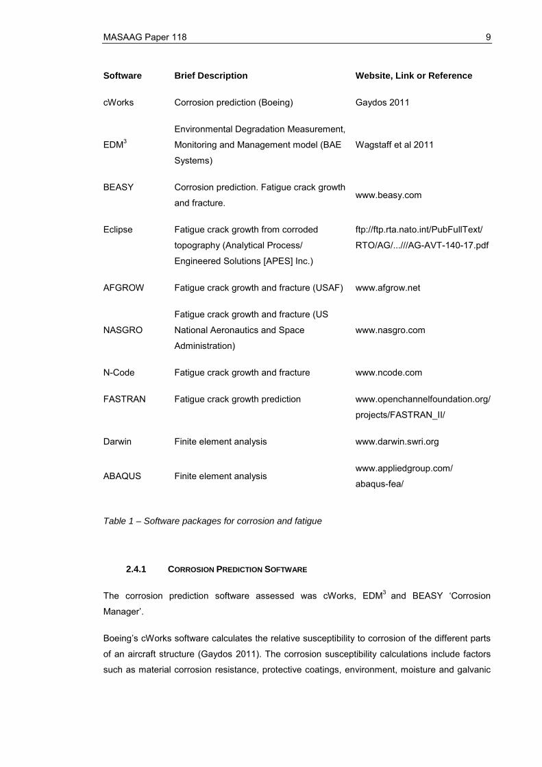
Software Brief Description Website, Link or Reference
cWorks Corrosion prediction (Boeing) Gaydos 2011
EDM3
Environmental Degradation Measurement,
Monitoring and Management model (BAE
Systems)
Wagstaff et al 2011
BEASY Corrosion prediction. Fatigue crack growth
and fracture. www.beasy.com
Eclipse Fatigue crack growth from corroded
topography (Analytical Process/
Engineered Solutions [APES] Inc.)
ftp://ftp.rta.nato.int/PubFullText/
RTO/AG/...///AG-AVT-140-17.pdf
AFGROW Fatigue crack growth and fracture (USAF) www.afgrow.net
NASGRO
Fatigue crack growth and fracture (US
National Aeronautics and Space
Administration)
www.nasgro.com
N-Code Fatigue crack growth and fracture www.ncode.com
FASTRAN Fatigue crack growth prediction www.openchannelfoundation.org/
projects/FASTRAN_II/
Darwin Finite element analysis www.darwin.swri.org
ABAQUS Finite element analysis www.appliedgroup.com/
abaqus-fea/
Table 1 – Software packages for corrosion and fatigue
2.4.1 CORROSION PREDICTION SOFTWARE
The corrosion prediction software assessed was cWorks, EDM3 and BEASY ‘Corrosion
Manager’.
Boeing’s cWorks software calculates the relative susceptibility to corrosion of the different parts
of an aircraft structure (Gaydos 2011). The corrosion susceptibility calculations include factors
such as material corrosion resistance, protective coatings, environment, moisture and galvanic

10 MASAAG Paper 118
interactions (e.g. from the presence of fasteners). The results are then used to determine
corrosion-based inspection intervals for existing aircraft or to mitigate the corrosion risk for
future designs.
EDM3 is an approach being developed by BAE Systems to manage corrosion on land, sea and
air platforms (Wagstaff et al 2011). It allows the user to determine when there is a requirement
to repaint the platform to minimise corrosion damage. The approach includes the use of data on
coating degradation and metal loss obtained from sensors on the platform as inputs to
environmental degradation models to estimate future damage in the present or future
environments. The sensors are able to monitor pitting corrosion and can detect pits with
diameters of less than 50 microns, which compares with 100-200 microns by visual inspection.
BEASY ‘Corrosion Manager’ software is designed for the assessment of the risk to components
and structures of galvanic corrosion and the effectiveness of surface protection systems
(BEASY 2012a). It will predict the location of corrosion in a structure and the corrosion rate. This
software has been used, for example, to predict the corrosion between steel bolts and
aluminium structure.
The corrosion prediction software is, in general, designed to aid in the selection of materials and
protection schemes, to identify areas of the structure which are susceptible to corrosion,
calculate corrosion rates and to assess, for example, when re-painting or other maintenance will
be required. Galvanic corrosion (cWorks, BEASY) and pitting corrosion (EDM3) are addressed.
The prediction of fatigue crack nucleation at corrosion pits is likely to require prediction of the
evolution of pit parameters such as width or depth (see Section 3.3). Programmes such as
EDM3 may be able to provide some of this data but further assessment of the capabilities of the
software is required. Further discussion of corrosion prediction is given in Section 3.2.
2.4.2 FATIGUE AND FRACTURE SOFTWARE
There are a large number of codes for the prediction of fatigue and fracture behaviour under
constant amplitude and spectrum loading. Examples in Table 1 include AFGROW, NASGRO,
FASTRAN, BEASY and N-Code, whilst in-house codes are also used by many organisations.
The software may be used to predict fatigue crack growth from corrosion damage by, for
example, using suitable flaws to represent the corrosion damage morphology. This approach is
used in the ECLIPSE software (Table 1) and measured corrosion morphology data has been
used as an input to BEASY software in an investigation of the nucleation and growth of fatigue
cracks from multiple corrosion pits (BEASY 2012b). Material property changes as a result of
corrosion may also be included in the analysis. Corrosion fatigue, i.e. fatigue crack growth in a
corrosive environment, may be modelled by using suitable fatigue crack growth data or S-N
MASAAG Paper 118 11
data, as appropriate, in the models. The modelling of fatigue crack growth from corrosion
damage and of corrosion fatigue is discussed further in Section 4.
2.4.3 PREDICTION OF CORROSION AND FATIGUE
The software packages found were primarily for the prediction of either corrosion (Section 2.4.1)
or fatigue (Section 2.4.2). The prediction of a complete corrosion-fatigue interaction process is
therefore likely to require the combination of a number of codes. The software used would
probably depend upon the precise situation being modelled, the available codes and their
compatibility. It may be necessary for instance to combine a finite element code for stress
analysis of the structure (e.g. ABAQUS or Darwin in Table 1) with a corrosion prediction code
(e.g. EDM3) and a fatigue and fracture code (e.g. AFGROW) to model the complete corrosion
and fatigue process. The corrosion prediction packages would have to provide suitable inputs to
the fatigue software, which might include parameters for material thinning (increased stress
and/or reduced stiffness), the development of corrosion pits (stress concentrations) or the
development of corrosion products (changed material properties and/or or stress state) as
discussed further in Section 4.
2.4.4 PROBABILISTIC APPROACHES
It was suggested in Section 2.3 that probabilistic approaches may ultimately be used for the
prediction of corrosion-fatigue interactions. There are a number of methods which could take
into consideration the uncertainty in the physical, mechanical, chemical, geometrical and
loading variables. These include interval analysis, fuzzy variables, first and second order
reliability methods and Monte Carlo simulations. The precise method to be adopted would
depend upon factors such as the degree of complexity, accuracy and cost effectiveness. The
finite element packages included in Table 1, i.e. ABAQUS and Darwin, have probabilistic
capabilities which are potentially applicable to corrosion-fatigue interactions but are largely
untested for this application.
12 MASAAG Paper 118
3 CORROSION AND FATIGUE CRACK INITIATION
3.1 STRUCTURALLY SIGNIFICANT CORROSION TYPES
Some discussion of corrosion types in aircraft structures has been given in Section 2.2.3. The
structurally significant types of corrosion include general attack, pitting corrosion, intergranular
corrosion, exfoliation corrosion, crevice corrosion, galvanic corrosion, corrosion fatigue, stress
corrosion cracking, hydrogen embrittlement and fretting fatigue (Mills et al 2009). These are
briefly described below, along with their potential effects on fatigue crack initiation and growth.
3.1.1 GENERAL ATTACK
General attack is widespread corrosion, with similar damage throughout the corroded region. It
may also involve hydrogen embrittlement or secondary bending and local stress raisers from
surface roughness (Mills et al 2009). Material thickness loss can result from the corrosion or
from the blending-out of the corrosion damage, and this net-section loss can increase general
stress levels, with detrimental effects upon the fatigue behaviour. The local stress raisers may
also promote the nucleation of fatigue cracks.
3.1.2 PITTING CORROSION
Pitting corrosion results from the attack of surface impurities and weak spots by the corrosive
environment (Mills et al 2009). Alloys susceptible to this type of corrosion include 2024-T3
aluminium alloys and steels such as those mentioned in Section 2.2.2. The corrosion produces
isolated pits in the surface of the structure, which provide local stress concentrations from which
fatigue cracks can grow (e.g. Mills et al 2002). The nucleation and growth of fatigue cracks from
corrosion pits has been widely studied, often with modelling of fatigue crack growth from surface
flaws whose dimensions are dependent upon those of the corrosion pits (see Section 3.3).
3.1.3 INTERGRANULAR AND EXFOLIATION CORROSION
Intergranular corrosion is the preferential corrosion of material at grain boundaries (Mills et al
2009). High-strength 7000-series aluminium alloys, for instance, can be susceptible because of
the accumulation of alloying elements such as copper and zinc at the grain boundaries.
Exfoliation corrosion is a particular form of intergranular corrosion. The corrosion proceeds from
the initiation sites along planes parallel to the surface – generally at grain boundaries – and

MASAAG Paper 118 13
forms corrosion products that force metal away from the body of the material. This gives a
layered appearance in the corroded material. Exfoliation corrosion can influence fatigue
cracking by similar mechanisms to pitting corrosion (Mills et al 2009). Modelling has been
carried out using similar methods to those for pitting corrosion, e.g. Liao et al (2007) modelled
fatigue crack growth from exfoliation damage by representing the exfoliation damage by a
surface crack.
The effects of the exfoliation corrosion products may need to be considered in assessing
potential corrosion-fatigue interactions. The products will most probably have different material
properties to the parent material. The stress state in a corroded structure may also be modified
by the restraint of the corroded material – including the corrosion products – by the surrounding
structure. An example is that the clamping forces exerted by fasteners – and the fatigue
performance of a structural joint – may be increased if corrosion products result in tightening of
the joint, or decreased if the joint is loosened by material loss, such as may occur in a corrosive
environment (Terada 2001).
3.1.4 GALVANIC AND CREVICE CORROSION
As discussed in Section 2.2.3, corrosion types such as galvanic or crevice corrosion are
produced by different mechanisms but have similar effects on the structure to general attack,
pitting or intergranular corrosion.
Galvanic corrosion can cause greatly increased corrosion rates in the susceptible material when
dissimilar materials are in contact (Mills et al 2009). This type of corrosion might occur, for
example, between titanium or steel fasteners and an aluminium alloy aircraft structure. Galvanic
corrosion has occurred in the F-22 as the result of the interaction of gap filler materials and paint
with aluminum panels, skins, and substructure (Young and Blair 2011).
In crevice corrosion, the occluded environment in the crevice configuration can accelerate
corrosion rates (Mills et al 2009). The growth of fatigue cracks from pits produced by crevice
corrosion in 2024-T3 aluminium alloy has been studied by Birt et al (2007).
3.1.5 ENVIRONMENTALLY-ASSISTED CRACKING AND FRETTING FATIGUE
Truly synergistic corrosion-fatigue interactions include environmentally-assisted cracking (EAC)
and fretting fatigue (Mills et al 2009). EAC processes include corrosion fatigue, stress corrosion
cracking (SCC) and hydrogen embrittlement.
14 MASAAG Paper 118
Corrosion fatigue is simultaneous corrosion and fatigue, when the fatigue crack growth rates
can be very sensitive to the environment. As an example, an aggressive aqueous environment
can accelerate fatigue crack growth rates by an order of magnitude in high-strength 7150-T651
aluminium alloy (Gingell and King 1997).
SCC will only take place when three conditions are satisfied, with (1) a susceptible material
subjected to (2) a sustained tensile stress in (3) a corrosive environment (Mills et al 2009).
Fatigue cracking may then develop from the SCC (e.g. Ball et al 2010).
Hydrogen embrittlement is the result of hydrogen produced by the corrosion process becoming
trapped in the material and thereby altering the material properties (Mills et al 2009). This can
result in, for example, degradation of the fracture behaviour of high-strength steels used in
landing gear (Eliaz et al 2002) or a dramatic tensile ductility loss in 2024-T3 aluminium alloy
(Kermanidis et al 2006). Enhanced fatigue crack growth can occur in aluminium alloys, steels
and titanium alloys exposed to different environments as a result of hydrogen embrittlement
(Hénaff et al 2007).
Fretting fatigue is the result of combined corrosion and wear, when oscillatory small-amplitude
relative displacements of mating surfaces take place in the presence of contact forces (Mills et
al 2009). The contact forces can lead to stress gradients similar to those at a notch and the
oxide debris can produce surface damage such as pitting. Either of these could contribute to the
accelerated formation of fatigue cracks.
3.2 CORROSION PREDICTION
The large number of variables affecting corrosion (see Section 2.2) means that corrosion
prediction methods should be relevant to the particular situation being considered e.g. it should
consider the specific materials and corrosion types in the structure. Corrosion prediction
modelling for USAF KC-135 lap joints was, for example, limited to crevice corrosion even
though other corrosion types were present (Robertson 1999).
An initial assessment of available software for corrosion prediction was made in Section 2.4.1.
The existing corrosion prediction software is in general designed for the prediction of corrosion-
related maintenance activities and the susceptibility of a structure to corrosion, rather than
predicting the development of features such as corrosion pits which can determine whether
fatigue cracks will initiate (see Section 3.3). However, software of this type should be able to
identify areas of the structure that are most prone to the development of corrosion. They may
also allow estimates to be made of general material thinning which could be required for stress
analysis of the structure e.g. the BEASY software will provide estimates of corrosion rates.

MASAAG Paper 118 15
However, software such as EDM3, which can provide information on corrosion pit development,
may be important for the assessment of whether fatigue cracks will initiate from corrosion
damage (see Section 3.3). The predictions may need to include the shape of the pits (e.g. the
ratio of width to depth) – e.g. this generally differs between 2024 and 7075 aluminium alloys –
as this can alter the stress concentration factor of the pit and hence the fatigue crack
development. Possible approaches to the prediction of corrosion pit growth range from the use
of simple relationships between pit dimensions and time such as Faraday’s Law – i.e. the
increase in the pit width and depth are proportional to the cube root of the exposure time in the
corrosive environment (Birt et al 2007) – to probabilistic approaches such as that of Rajasankar
and Iyer (2006). An example of a corrosion prediction methodology for the onset and growth of
corrosion pitting in aircraft structure is given by Dixon et al (2003).
The complexity of the physical processes underlying corrosion mechanisms, together with the
variability associated with, for example, environmental or metallurgical factors, may mean that it
is not possible to accurately predict the corrosion development by analytical methods and it may
be necessary to resort to empirical approaches (Nesic et al 2001). The data for the development
of such approaches might be obtained from NDE measurements of corrosion damage
parameters (see Section 3.4) or from maintenance data for aircraft structures (Section 3.5).
Various methods may be used for the treatment of the data, e.g. Nesic et al (2001) used neural
networks for the analysis of corrosion data.
3.3 INITIATION OF FATIGUE CRACKS FROM CORROSION
The initiation of fatigue cracks from corrosion damage has been studied for a range of structural
materials, including aluminium alloys (e.g. Burns et al 2011) and steels (e.g. Ebara 2010).
These studies have in general addressed the initiation of fatigue cracks from corrosion pits,
since the stress concentrations at the pits make them the most likely corrosion damage features
at which fatigue cracks will initiate. The size and morphology of the corrosion pits can have
significant effects upon the fatigue crack nucleation (e.g. van der Walde and Hilberry 2008) and
some investigations have carried out detailed investigation of the effects of pit topography and
material microstructure upon fatigue crack initiation (e.g. Burns et al 2011). BEASY (2012c)
describes a study of the effect of corrosion pit shape upon the stress concentration factor, whilst
Rusk et al (2009) have developed an equivalent stress-raiser model for the nucleation of fatigue
cracks at corrosion pits in high-strength steel. The utility of corrosion prediction software such as
that assessed in Section 2.4.1 in predicting the nucleation of fatigue cracks from corrosion
damage is therefore likely to depend upon their ability to predict the evolution of those pit
characteristics that will have an influence upon the crack nucleation. It is therefore
recommended that further assessment of software for corrosion prediction (see Section 2.4.1)
16 MASAAG Paper 118
should be made to establish its suitability for the prediction of fatigue crack nucleation from
corrosion damage.
Whilst the nucleation of fatigue cracks from corrosion damage may be able in some cases (e.g.
from a single dominant corrosion pit) to be predicted by detailed modelling of the corrosion
surface including the pit morphology, it may not always be possible to use this approach and
approximate or empirical methods may be required instead. As an example, Rusk et al (2009)
have developed approximate methods to identify localized high stress regions in corroded steel
surfaces because the finite element mesh that would be required to accurately reflect the fine
details distributed over the entire corrosion patch makes computation unrealistic. Empirical
relationships between corrosion pit parameters and fatigue behaviour have also been
developed and these are discussed further in Section 3.4.
3.4 NDE CORROSION PARAMETERS
A review of the important corrosion metrics that need to be measured so that remaining life can
be predicted from fatigue crack growth models was reported by Birt et al (2006). The type of
corrosion taking place was identified as an initial metric for life prediction and the remaining
fatigue life was found to be strongly correlated with the presence of corrosion pits, with pit depth,
pit area and surface roughness all reported as important metrics. DuQuesnay et al (2003)
reported that the corrosion pit depth appeared to be the dominant factor affecting the fatigue life
of 7075-T6511 aluminium alloy, whilst Rokhlin et al (1999) have determined an empirical
relation between the depth of a single, simulated corrosion pit and the fatigue life of 2024-T3
aluminium alloy. If there is a dominant corrosion pit, measurement of the appropriate pit
dimensions may therefore allow their use as inputs to fatigue life prediction models as
discussed in Section 4.1.
Birt et al (2007) found good correlations of the fatigue lives of 2024-T3 aluminium alloy
specimens containing pitting and crevice corrosion with ultrasonic and eddy-current NDE
parameters such as the mean and standard deviation of 50 MHz ultrasonic back-wall amplitude
C-scans. Shell et al (2005) have also found correlations between corrosion metrics, obtained by
ultrasonic inspection, white-light interference microscopy (WLIM) and radiography, with the
fatigue lives of 2024-T3 specimens containing a mix of pitting, intergranular and general
corrosion.
Shell et al (2005) reported that using the combined metrics of WLIM roughness and maximum
loss in back-wall ultrasonic amplitude gave a significant improvement in the correlation of the
NDE parameters with fatigue life. An earlier paper by Forsyth and Komorowski (2000) had also
evaluated combining NDE data for fatigue-life prediction. This combining of data is often
MASAAG Paper 118 17
referred to as data fusion, which is simply defined as combining multiple inputs into one output.
The inputs can be from different NDE techniques (e.g. Forsyth and Komorowski 2000) or
different parameters from the same NDE technique (e.g. roughness and thickness loss using an
ultrasonic method, as Smith 2004). Data fusion for a lap joint, where both eddy-current and
enhanced visual NDE techniques were required to fully characterise the corrosion damage, was
described by Forsyth and Komorowski (2000) and Liu and Forsyth (2004).
It is recommended that the use of NDE data fusion techniques for the prediction of corrosion-
fatigue interactions should be investigated further. The data fusion techniques might potentially
give improved accuracy of predictions compared to a single technique (e.g. Shell et al 2005).
However, this investigation should consider in particular whether more rapid inspection of a
structure to obtain suitable inputs to predictive models might be possible with a combination of
techniques (e.g. general thickness loss and surface roughness) than by detailed corrosion pit
measurements using a single technique, which might be prohibitively lengthy and so only
suitable for areas of the structure which are of particular concern.
3.5 MAINTENANCE AND OTHER DATA
The use of in-service data from maintenance and other records to build up a model of corrosion
in a particular aircraft type is being developed, for example in the United States (Benavides
2009), because of the difficulty of predicting corrosion from mechanistic models. Appendix A
gives examples of how corrosion costs for different aircraft types may give indications of the
development of corrosion in the aircraft. The data in the appendix is limited to total annual cost
per aircraft and so give only very general indications. However, data recorded in sufficient detail
and with sufficient accuracy from in-service corrosion data from inspections, maintenance and
teardown may be used in the more detailed prediction of corrosion development within the
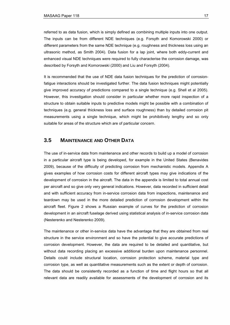
aircraft fleet. Figure 2 shows a Russian example of curves for the prediction of corrosion
development in an aircraft fuselage derived using statistical analysis of in-service corrosion data
(Nesterenko and Nesterenko 2009).
The maintenance or other in-service data have the advantage that they are obtained from real
structure in the service environment and so have the potential to give accurate predictions of
corrosion development. However, the data are required to be detailed and quantitative, but
without data recording placing an excessive additional burden upon maintenance personnel.
Details could include structural location, corrosion protection scheme, material type and
corrosion type, as well as quantitative measurements such as the extent or depth of corrosion.
The data should be consistently recorded as a function of time and flight hours so that all
relevant data are readily available for assessments of the development of corrosion and its
18 MASAAG Paper 118
interaction with fatigue. Fatigue data, e.g. the presence or length of fatigue cracks or loads data,
might also be required for the assessment of potential corrosion-fatigue interactions. United
States Navy maintenance data processes had to be developed to allow recording of inspection
and repair corrosion data (Savell et al 2011) and it may be that UK maintenance databases
would also need to be modified to allow the recording of suitable data.
0.0
0.4
0.8
1.2
1.6
2.0
0 2 4 6 8 10 12 14
Service life (years)
Corr
osio
n de
pth
(mm
)
Figure 2 – In-service corrosion data and examples of derived curves for the prediction of corrosion damage development in a Russian aircraft fuselage of D16ATV aluminium alloy (Nesterenko and Nesterenko 2009)
It is therefore recommended that the potential use of maintenance data for the prediction of
corrosion and its possible combination with fatigue data for assessment of potential corrosion-
fatigue interactions should be investigated. This assessment should include, for example, the
type of data available and whether it would be suitable for corrosion prediction, either
qualitatively (e.g. identifying the materials or structural elements most susceptible to corrosion)
or quantitatively; the methods of recording and storing the data and whether these would need
to be modified; combination of the data with any records from corrosion sensors or aircraft
geographical history to allow for effects of environment (see Section 2.2.4) and possible
analysis methods for the data.
MASAAG Paper 118 19
4 FATIGUE CRACK GROWTH
4.1 FATIGUE CRACK GROWTH FROM CORROSION
The general interaction of fatigue and corrosion was illustrated schematically in Figure 1. The
later stages are often predicted using available fatigue and fracture software such as that
discussed in Section 2.4. The fatigue prediction may be based upon the growth of an initial flaw
with parameters which are related to the dimensions of a corrosion pit, such as a semi- or
quarter-elliptical flaw of equivalent area to the observed corrosion pit (Gruenberg et al 2004,
Van der Walde and Hilberry 2008). As previously noted, factors such as material thinning
(higher stresses) and the formation of corrosion products (different material properties, e.g.
Bellinger and Liao 2009) may need to be included in the fatigue analysis. The possibility of the
interaction of multiple fatigue cracks from corrosion pits may also need to be considered, e.g.
van der Walde et al (2005).
The initiation of the fatigue crack at the corrosion damage can depend upon the morphology of
the corrosion pit and the resultant stress concentration, as discussed in Section 3.3. A
conservative approach sometimes used is to assume immediate initiation of the crack from the
corrosion pit, e.g. Burns and Gangloff (2011) for 7000-series aluminium alloys.
As a fatigue crack may grow from a small (of the order of tens of microns) corrosion pit, short
crack fatigue behaviour may need to be included in the model to give accurate fatigue
predictions. Birt et al (2007) found that the assumed short crack behaviour significantly altered
the predicted life of corroded 2024-T3 specimens.
The fatigue crack growth may be influenced by a corrosive environment, e.g. the crack growth
rate may be altered by anodic dissolution or hydrogen embrittlement of the material (e.g. Hénaff
et al 2007). Corrosion fatigue data may be required to model the crack growth, but should be
appropriate to the environmental conditions present in service, e.g. the fatigue of 2024
aluminium alloy differs in air, distilled water and 3.5% NaCl solution (Menan and Hénaff 2010),
the last being the approximate composition of seawater. The effect of the loading frequency and
sequencing may also need to be considered (see Section 2.2.6).
Environmental exposure may result in changes in the static properties of the structural material,
e.g. Kermanidis et al (2006) and Kamoutsi et al (2006) for 2024-T3 aluminium alloy. Such
changed material properties might need to be used in, for example, calculation of the effects of
overloads in spectrum loading upon the plastic zone at the fatigue crack tip, or in determination
of the fracture behaviour of the material. Billy et al (2012) reported that fatigue tests of 2024-

20 MASAAG Paper 118
T3511 panels removed from an Airbus A320 wing after service showed no significant
differences from virgin material, thereby supporting the use of pristine material fatigue data in
prediction.
In addition to life prediction, fatigue calculations might also be used to back-calculate from the
required fatigue life to determine allowable damage, such as pit dimensions, for the structure.
This might then set the allowable limits for NDE inspections using techniques such as those
discussed in Section 3.4, provided that a satisfactory correspondence can be established
between the calculated corrosion parameters and the actual corrosion morphology
4.2 SPECTRUM LOADING AND ENVIRONMENT
Most research on corrosion-fatigue interactions has been for constant amplitude loading, e.g.
fatigue crack growth from pre-corroded specimens in laboratory air (Birt et al 2007) or corrosion
fatigue in environments such 3.5% NaCl solution (Menan and Hénaff 2010). There is less work
for corrosion-fatigue interactions under spectrum loading, which can also result in severe
reductions in fatigue lives, e.g. for crack growth from corrosion pits in 7075-T76511 aluminium
alloy under a Canadian C-130 transport wing spectrum (DuQuesnay et al 2003). Figure 3 shows
the results of modelling to predict the effects upon fatigue life of a 50-micron corrosion pit and
different material thickness losses in an aircraft lower wing under a C-130 spectrum (Mills et al
2009).
0
10000
20000
30000
40000
50000
60000
No corrosion 50μm pit 50μm pit + 5%thickness loss
50μm pit +10% thickness
loss
50μm pit +20% thickness
loss
50μm pit +30% thickness
loss
Spec
trum
flig
ht h
ours
to fa
ilure
Figure 3 – Example of modelling results for fatigue crack growth from corrosion damage under C-130 lower wing spectrum loading (Mills et al 2009)
MASAAG Paper 118 21
The corrosion-fatigue interaction effects may be different for spectrum loading and constant-
amplitude loading, e.g. the presence of a salt spray increased fatigue crack growth rates by a
factor of three in 7010-T7451 aluminium alloy under constant amplitude loading, but the salt
spray had no significant effect upon the crack growth rate for the same alloy under spectrum
loading (Cole et al 1997). It is possible, for example, that mechanisms such as changes in crack
closure as a result of overloads in the spectrum alter moisture ingress into a crack and so give
different corrosion-fatigue interactions to those under constant amplitude loading.
It is therefore recommended that corrosion-fatigue interactions under spectrum loading should
be investigated further. This should include fatigue crack growth nucleation and growth from
corrosion pits under spectrum loading, and fatigue in a corrosive environment under spectrum
loading. The appropriate modifications required to existing fatigue software required for
improved predictions could then be determined. Such modifications might include, for example,
the use of modified materials properties in the models to allow for the effects of corrosion (see
section 4.3).
Corrosion-fatigue interactions under spectrum loading are dependent upon the material type as
well as the loading spectrum. Spectrum loading of clad aluminium alloys, for example, gave
similar crack propagation rates in indoor and outdoor environments for 2024-T3, but in 7075-T6
the outdoor crack growth rates were a factor of about 1.5 to 2.0 greater than the indoor rates
(Schijve and De Rijk 1965). In specimens immersed in salt water, tensile overloads in the
loading spectrum produced fatigue crack growth retardation in 2024-T851 and Ti-6Al-6V-2Sn
alloys immersed in salt water, much as they would in benign environments, but similar
overloads produced crack extension, consistent with SCC, in Ti-6Al-4V (Cole et al 1997). The
type of material, corrosion, environment and loading spectrum should thus be considered
carefully for any future investigations of corrosion-fatigue interactions under spectrum loading.

22 MASAAG Paper 118
5 CONCLUSIONS
Corrosion and fatigue in an aircraft structure may interact in a number of ways. This can include
the more rapid initiation of fatigue cracks as a result of corrosion damage or changes in fatigue
crack growth rates due to the presence of a corrosive environment. These interactions can lead
to increased risks to aircraft structural integrity, increased maintenance costs and reduced
aircraft availability.
Corrosion and fatigue, and their interactions, are dependent upon many factors. These include,
for example, material type, corrosion type, structural configuration, environment and applied
load spectrum. The variability associated with these factors and the dependence of many of
them on micro-structural details make prediction of corrosion-fatigue interaction processes (e.g.
the initiation of fatigue cracks from corrosion damage) difficult. This potential variability also
means that predictions of corrosion-fatigue interactions should specifically address the factors
relevant to a given situation (e.g. operating environment).
A generalised corrosion-fatigue process may be broken down into a number of stages. This can
aid in developing prediction methods and in assessing the suitability of different approaches to
the individual stages. The methods to be used for each stage will depend upon the physical
situation and the available approaches. Established approaches and available software should
be used as far as possible for the prediction of corrosion-fatigue interactions, as this will
minimise time and effort and should increase confidence in the outputs. Advances such as the
availability of new software, new approaches such as the use of probabilistic techniques or new
methods for corrosion prediction could then be incorporated in the appropriate stages as they
become available.
A variety of software is available for the prediction of corrosion or fatigue. The corrosion
prediction software can address galvanic and pitting corrosion, corrosion rates and the effects of
protective coatings and may calculate, for example, the relative susceptibility of different parts of
the aircraft structure to corrosion. The fatigue prediction software may calculate, for example,
fatigue crack growth from a corrosion pit under applied spectrum loading. It may be necessary
to combine a number of these packages to assess a particular corrosion-fatigue interaction.
This might involve a finite element package for calculation of the stresses in a structural feature,
a corrosion prediction model to assess the growth of corrosion pits, and a fatigue and fracture
code to predict the fatigue crack growth from the corrosion pits through to the final fracture.
There are a number of structurally significant corrosion types but the most important are
probably general attack, pitting corrosion and exfoliation corrosion. The effects of other
corrosion types such as crevice corrosion upon fatigue behaviour may be modelled by similar

MASAAG Paper 118 23
approaches to these three types. Corrosion features which will influence fatigue behaviour
include thickness loss (increased stress levels and/or reduced stiffness), corrosion pits (stress
concentrations) and corrosion products (changed materials properties and/or stress state).
Fatigue crack growth prediction is in general more advanced than corrosion prediction. The
most immediate benefits from the prediction of corrosion-fatigue interactions may thus be
realised by improving the accuracy of prediction of fatigue crack growth from corrosion damage
and of corrosion fatigue. Such improvements might also allow accurate back-calculation from
the required fatigue lives to determine acceptable levels of corrosion in the structure (e.g.
corrosion pit dimensions). The effects of corrosion upon fatigue behaviour under aircraft
spectrum loading may be different to those for the constant amplitude loading used in much
previous work. It may be possible to adapt existing fatigue and fracture software to allow for the
effects of corrosion by using suitably modified static material properties and fatigue behaviour.
However, consideration needs to be given to the applicability of material data obtained in the
laboratory to actual service conditions.
The initiation of fatigue cracks from corrosion damage is mostly from corrosion pits and is
therefore highly dependent upon the pit geometry. The prediction of fatigue crack nucleation
and growth from corrosion damage may therefore require the ability to predict the evolution of
the geometrical factors in the corrosion pits that influence crack nucleation in addition to, for
example, the general level of corrosion.
NDE methods can provide detailed measurements of corrosion damage, such as the
dimensions of corrosion pits, which can provide inputs to fatigue crack growth software.
However, the time and effort required for NDE scanning and fatigue analysis may mean that the
use of such detailed data is only practicable for relatively small areas of structure which are of
particular concern. Data fusion is the combination of a number of NDE techniques which should
potentially allow more rapid scanning to determine the corrosion state of a structure and so
could be a practical means of providing suitable inputs to fatigue models. An example of data
fusion might be the combination of NDE techniques to measure material thickness loss and
surface roughness.
Data from the maintenance effort required to repair corrosion damage may be used for the
prediction of corrosion in an aircraft structure. This approach has the advantage that the data
are obtained for real structures and actual service environments. However, the processes for
the recording and analysis of the data must be carefully designed to accurately provide the
relevant quantitative information without excessive additional effort on the part of the
maintenance organisation.
24 MASAAG Paper 118
6 RECOMMENDATIONS
6.1 GENERAL CONSIDERATIONS
Established approaches and available software should be used as far as possible for the
prediction of corrosion-fatigue interactions (Section 2.3).
Each potential corrosion-fatigue interaction process should be broken down into a series of
stages to determine the optimum approach and software to be used in each stage (Sections 2.1
and 2.3).
Assessments of potential corrosion-fatigue interactions should allow for factors such as the
specific material or corrosion type because of the variability due to these factors (Sections 2.2
and 4.2).
6.2 PREDICTION OF CORROSION-FATIGUE INTERACTIONS
The use of existing fatigue and fracture software for the prediction of fatigue crack growth from
corrosion damage should be investigated for aircraft structural features subjected to spectrum
loading in realistic service environments (Section 4.2).
Corrosion prediction methods should be assessed for their ability to predict the evolution of the
geometrical parameters of corrosion pits which will influence the nucleation of fatigue cracks at
the pits (Sections 3.2 and 3.3).
The use of NDE data fusion methods for obtaining corrosion damage input parameters to
fatigue software should be investigated (Section 3.4).
A review should be made of the available data for corrosion and fatigue development obtained
during maintenance and other activities to assess the potential of the data for use in the
prediction of corrosion-fatigue interactions (Section 3.5).
MASAAG Paper 118 25
REFERENCES
BALL D L, LOUGHEED J C, INGRAM J E and BURKE T P (2010), "CBM+ Viability for a Large Transport Aircraft", USAF Aircraft Structural Integrity Program Conference, San Antonio, Texas
BEASY (2012a), Corrosion Manager, Product Data Sheet, Ashurst, Southampton
BEASY (2012b), Assessment of Corrosion Pit Damage, Fracture and Crack Growth Case Study, Ashurst, Southampton
BEASY (2012c), Assessment of Corroded Surfaces, Fracture and Crack Growth Case Study, Ashurst, Southampton
BELLINGER N C and LIAO M (2009), “Corrosion and fatigue modeling of aircraft structures”, in Benavides S (Ed), Corrosion Control in the Aerospace Industry, Woodhead Publishing and CRC Press, 172-191
BENAVIDES S (2009), “Corrosion in the aerospace industry” in Benavides S (Ed), Corrosion Control in the Aerospace Industry, Woodhead Publishing and CRC Press, 1-14
BILLY F, BENOIT G and HENAFF G (2012), “Fatigue resistance of wing materials from the teardown of AIRBUS A320 aircraft at the end of life”, Aircraft Airworthiness & Sustainment Conference, Baltimore, Maryland, 2-5 April
BIRT E A, JONES L D, NELSON L J and SMITH R A (2006), “NDE corrosion metrics for life prediction of aircraft structures,” Insight 48 139-143
BIRT E A, NELSON L J, BROWN K, JONES L D, YOUNG A and SMITH R A (2007), “Correlation of fatigue life with potential NDE corrosion metrics,” Insight 49 402-408
BURNS J T and GANGLOFF R P (2011), “Scientific advances enabling next generation management of corrosion induced fatigue”, Procedia Engineering 10 362–369
BURNS J T, LARSEN J M and GANGLOFF R P (2011), “Driving forces for localized corrosion-to-fatigue crack transition in Al-Zn-Mg-Cu”, Fatigue and Fracture of Engineering Materials and Structures 34 745-773
COLE G K, CLARK G and SHARP P K (1997), The Implications of Corrosion with respect to Aircraft Structural Integrity, Defence Science and Technology Organisation Report DSTO-RR-0102, Melbourne, Australia
CLARK G (2010), “Aircraft Structural Integrity: An Australian Perspective”, USAF Aircraft Structural Integrity Program Conference, San Antonio, Texas
COUDERT E and RENAUDIN C (1998), “Variable amplitude corrosion fatigue behaviour and hydrogen embrittlement of high strength steels for off-shore applications”, Proc 8th International Offshore and Polar Engineering Conference, Montreal, Canada, May 24-29
DIXON D, HARRIS S J and COLE I S (2003), “A Corrosion Prediction Model and Corrosion Sensors for Corrosion Management”, Tri-Service Corrosion Conference, Las Vegas, Nevada, November
26 MASAAG Paper 118
DRAGAN K, KLIMASZEWSKI S and LESKI A (2005), “NDE Approach for Structural Integrity Evaluation of MiG-29 Aircraft”, USAF Aircraft Structural Integrity Program Conference, Memphis, Tennessee
DUQUESNAY D L, UNDERHILL P R and BRITT H J (2003), "Fatigue crack growth from corrosion damage in 7075-T6511 aluminium alloy under aircraft loading", Int. J Fatigue 25 371-377
EASTAUGH G F, MERATI A A, SIMPSON D L, STRAZNICKY P V, SCOTT J P, WAKEMAN R B and KRIZAN D V (1999), “An experimental study of corrosion/fatigue interaction in the development of multiple site damage in longitudinal fuselage skin splices”, in Fatigue in the Presence of Corrosion, NATO RT-MP-18, pp. 20-1 to 20-16
EBARA R (2010), “Corrosion fatigue crack initiation behavior of stainless steels”, Procedia Engineering 2 1297-1306
ELIAZ N, SCHACHAR A, TAL B and ELIEZER D (2002), “Characteristics of hydrogen embrittlement, stress corrosion cracking and tempered martensite embrittlement in high-strength steels”, Engineering Failure Analysis 9 167-184
FALUGI M, HOEPPNER D W, EASTAUGH G F, BROOKS C L, PROST-DOMASKY S, HONEYCUTT K, GINTER T J, BELL R P and SHELTON D (2000), “Application of the Lockheed Martin Corrosion Fatigue Structural Demonstration Program to Corrosion Induced Damage on Aging Aircraft-Phase I and Phase II Plans”, Fourth Aging Aircraft Conference, St Louis, MO, May 15-18
FINDLAY S J and HARRISON N D (2002), “Why aircraft fail”, Materials Today, November, 18-25
FORSYTH D S and KOMOROWSKI J P (2000), “The role of data fusion in NDE for aging aircraft,” SPIE 3994, pp. 47-58
GAYDOS S (2011), “cWorks – Corrosion Control System”, ASETSDefense Workshop, February
GHIDINI T, ALFARO U and DONNE C D (2005), “Fatigue life of friction stir welded joints in the presence of corrosion damage: experiments and calculations”, Materials Testing 47 456-461
GINGELL A D B and KING J E (1997), “The effect of frequency and microstructure on corrosion fatigue crack propagation in high-strength aluminium alloys”, Acta mater 45 3855-2870
GRUENBERG K M, CRAIG B A, HILLBERRY B M, BUCCI R B and HINKLE J A (2004), “Predicting fatigue life of pre-corroded 2024-T3 aluminium,” Int. J Fatigue 26 629-640
HARLOW D G and WEI R P (2009), “Probability modeling and material microstructure applied to corrosion and fatigue of aluminum and steel alloys”, Engineering Fracture Mechanics 76 695–708
HENAFF G, ODEMER G and TONNEAU-MOREL A (2007), “Environmentally-assisted fatigue crack growth mechanisms in advanced materials for aerospace applications”, International Journal of Fatigue 29 1927–1940
HERTZBERG E (2009), “Assessing the Cost of Corrosion in the Aerospace Industry”, in Benavides S (Ed), Corrosion Control in the Aerospace Industry, Woodhead Publishing and CRC Press, 17-34
JANE’S (2011), “Russian Federation” in World Air Forces, on-line, posted 9 November
JASZTAL M and KOCANDA D (2012), "Probabilistic predicting the fatigue crack growth under variable amplitude loading", Int. J Fatigue 39 68-74

MASAAG Paper 118 27
JAYA A, TIONG U H, MOHAMMED R, BIL C and CLARK G (2010), “Corrosion treatments and the fatigue of aerospace structural joints”, Procedia Engineering 2 1523-1529
KAMOUTSI H, HAIDEMENOPOULOS G N, BONTOZOGLOU V and PANTELAKIS S (2006), "Corrosion-induced hydrogen embrittlement in aluminum alloy 2024", Corrosion Science 48 1209-1224
KERMANIDIS A T, STAMATELOS D G, LABEAS G N and PENTELAKIS S G (2006), “Tensile behaviour of corroded and hydrogen embrittled 2024 T351 aluminum alloy specimen”, Theoretical and Applied Fracture Mechanics 45 148–158
KINZIE R (2005), 2004 USAF direct costs of corrosion, US Department of Defense Corrosion Defense (CorrDefense) website, www.corrdefense.org, accessed 10 July 2012
LIAO M and KOMOROWSKI J P (2004), “Corrosion Risk Assessment of Aircraft Structures”, in Johnson W S and Hilberry B M (eds.), Probabilistic Aspects of Life Prediction, STP 1450, ASTM International, West Conshohocken, PA, 183-198
LIAO M, RENAUD G and BELLINGER N C (2007), "Fatigue modelling for aircraft structures containing natural exfoliation corrosion", Int. J Fatigue 29 677-686
LIU Z and FORSYTH D S (2004), “Registration of multi-modal NDI images for aging aircraft,” Research in NDE 15 1-17
MAA, RA 5720 - Structural Integrity Management, Issue 2
MAA, RA 5723 - Ageing Aircraft Audit, Issue 2
MAA, RA 5724 - Life Extension Programme, Issue 2
MENAN F and HENAFF G (2010), "Synergistic action of fatigue and corrosion during crack growth in the 2024 aluminium alloy", Procedia Engineering 2 1441-1450
MILLS T, PROST-DOMASKY S, HONEYCUTT K and BROOKS C (2009), “Corrosion and the threat to aircraft structural integrity” in Benavides S (Ed.), Corrosion Control in the Aerospace Industry, Woodhead Publishing and CRC Press, pp. 35-66
MILLS T, SHARP P K and LOADER C (2002), The Incorporation of Pitting Corrosion Damage into F-111 Fatigue Life Modelling, DSTO-RR-0237
NESIC S, NORDSVEEN M, MAXWELL N and VRHOVAC (2001), “Probabilistic modelling of CO2 corrosion laboratory data using neural networks”, Corrosion Science 43 1373-1392
NESTERENKO G I and NESTERENKO B G (2009), “Ensuring structural damage tolerance of Russian aircraft”, International Journal of Fatigue 31 1054-1061
NTSB (2008), Brief of Accident, SEA07LA217, National Transportation Safety Board, Washington DC, Adopted 31 March
PYE C R (1981), “Detection and prevention of corrosion in Royal Air Force aircraft”, in Aircraft Corrosion, AGARD Conference Proceedings No. 315, 2-1 to 2-10
RAJASANKAR J and IYER N R (2006), "A probability-based model for growth of corrosion pits in aluminium alloys", Eng. Fracture Mech. 73 553-570
28 MASAAG Paper 118
ROBERTSON D (1999), “Air Force Corrosion Prevention and Control Office Turns the Corner on Corrosion Prediction/Assessment”, AMPTIAC Newsletter Summer pp. 1-3, 7
ROKHLIN S I, KIM J Y, NAGY H and ZOOFAN B (1999), “Effect of pitting corrosion on fatigue crack initiation and fatigue life,” Eng. Fracture Mech. 62 425-444
RUSK D T, HOPPE W, BRAISTED W and POWAR N (2009), "Fatigue life prediction of corrosion-damaged high strength steel using an equivalent stress riser (ESR) model, Part II: Model development and results", Int. J Fatigue 31 1464-1475
SAVELL C T, WOODSON S, BORSOTTO M, BOATWRIGHT R and TUCKER C (2011), “Forecasting Aircraft Corrosion from NAVAIR Inspection and Repair Data”, Department of Defense Corrosion Conference, La Quinta, California, 31 July-5 August
SCHIJVE J and DE RIJK P (1965), The crack propagation in two aluminium alloys in an indoor and an outdoor environment under random and programmed load sequences, National Aerospace Laboratory (NLR) Report NLR-TR M.1256, The Netherlands
SHELL E B, BUCHHEIT R G and ZOOFAN B (2005), “Correlation of residual fatigue life with quantified NDE measurements,” Int. J Fatigue 27 105-112
SHI P and MAHADEVAN S (2001), "Damage tolerance approach for probabilistic pitting corrosion fatigue life prediction", Eng. Fracture Mech. 68 1493-1507
SMITH H, PEREZ R, SANKARAN K K, HOFFMAN P and HOFFMAN M (2001), “The effects of corrosion on fatigue life – A non-deterministic approach”, AIAA ASME SAE Structures, Structural Dynamics and Materials Conference
SMITH R A (2004), “Advanced ultrasound waveform analysis package for manufacturing and in-service use,” Proc. World Conf. on NDT, Paper WP46
SUN S, ZHENG Q, LI D and WEN J (2009),” Long-term atmospheric corrosion behaviour of aluminium alloys 2024 and 7075 in urban, coastal and industrial environments”, Corrosion Science 51 719–727
TERADA H (2001), “Structural fatigue and joint degradation”, International Journal of Fatigue 23 S21-S30
THETFORD O (1988), Aircraft of the Royal Air Force since 1918, Eighth edition, Putnam
TRATHEN P (2012), “Prediction of Corrosion Damage on RAAF P-3 Maritime Patrol Aircraft”, Aircraft Airworthiness & Sustainment Conference, Baltimore, Maryland, 2-5 April
VAN DER WALDE K, BROCKENBROUGH J R, CRAIG B A and HILLBERRY B M (2005), "Multiple fatigue crack growth in pre-corroded 2024-T3 aluminum", Int. J Fatigue 27 1509-1518
VAN DER WALDE K and HILLBERRY B M (2008), “Characterization of pitting damage and prediction of remaining life,” Int. J Fatigue 30 106-118
WAGSTAFF S, STURLAND I and PARFITT A (2011), “Environmental Degradation Measurement, Monitoring and Management (EDM3)”, Department of Defense Corrosion Conference, La Quinta, California, 31 July-5 August
YOUNG P and BLAIR R (2011), “F-22 Individual Aircraft Tracking Methodology for Corrosion”, USAF ASIP Conference, San Antonio, Texas, December

MASAAG Paper 118 29
Appendix A: Corrosion costs for USAF and RAF aircraft types
The cost of corrosion in aircraft structures was touched upon in Section 1. The actual costs of
aircraft corrosion may be difficult to quantify and require considerable effort to gather (Pye 1981).
Some cost data for USAF and RAF aircraft types are presented in this Appendix. The absolute
(USAF) or relative (RAF) costs are of importance for budgetary purposes, but trends in the
corrosion costs can also provide indications of the development of corrosion in aircraft
structures.
The corrosion cost data given here are manpower and materials costs for maintenance activities
related to corrosion. They include aircraft washing and cleaning; the application, inspection and
repair of paint schemes and protective coatings; the inspection for and rectification of corrosion
damage; and supporting activities such as gaining access to and closure from parts requiring
these activities. The relative costs therefore give indications of relative corrosion maintenance
effort and so potentially of relative susceptibility to corrosion and corrosion-fatigue interactions.
As discussed in Section 3.5, more detailed corrosion maintenance data may be able to be used
in corrosion prediction.
Figures A-1 and A-2 show the annual cost of corrosion per aircraft for different USAF aircraft
types (Kinzie 2005) plotted against time. The costs are all adjusted to 2004 dollars. Figure A-1
gives the data for the generally larger aircraft types, including bombers (shown in blue),
transports/tankers (red) and Intelligence, Surveillance and Targeting (ISTAR) aircraft (green).
Figure A-2 includes fighter/attack aircraft (in blue), training aircraft (red) and helicopters (green).
The individual helicopter types are not given, but at these dates the USAF operated MH-53, HH-
60 and UH-1 helicopters. For each category, the aircraft types are arranged in the key by
approximate date of service entry, with the oldest at the top. The approximate empty weight (in
tonnes) of each aircraft type is shown against the corresponding cost data in the figure. The
data for the aircraft (other than cost) were taken from a variety of sources (principally Jane’s
publications).
Table A-1 gives relative corrosion maintenance costs (Pye 1981) for RAF aircraft. Data other
than costs were taken from a range of sources, including Jane’s publications and Thetford
(1988). Aircraft characterised as “old” in the table had been introduced into RAF service 20 or
more years before the date of the review.

30 MASAAG Paper 118
82
8770
3561
170
125 773
78
67
0
250000
500000
750000
1000000
1250000
1988 1990 1992 1994 1996 1998 2000 2002 2004 2006
Year
Annu
al c
orro
sion
cos
t per
airc
raft
(200
4$)
B-52B-1B-2C-130C-135C-141C-5C-17U-2E-3E-8
Figure A-1 – Cost of corrosion (Kinzie 2005) for USAF bomber, transport/tanker and ISTAR aircraft (approximate empty weight in tonnes is indicated for each aircraft type)
13
9
9
14
2
4
3 to 10
0
50000
100000
150000
200000
250000
1988 1990 1992 1994 1996 1998 2000 2002 2004 2006
Year
Annu
al c
orro
sion
cos
t per
airc
raft
(200
4$)
F-15F-16A-10F-117T-37T-38Helicopters
Figure A-2 – Cost of corrosion (Kinzie 2005) for USAF fighter/attack aircraft, training aircraft and helicopters (approximate empty weight in tonnes is indicated for each aircraft type)

MASAAG Paper 118 31
Aircraft Category Example(s) Empty weight (tonnes)
Cost factor
Small training aircraft Jet Provost 2 1
Smaller combat aircraft
Modern land-based helicopter
Jaguar
Lightning
Puma
7
13
3
5
Larger combat aircraft
Modern marine environment helicopter
Phantom
Sea King
14
6
15
Medium-sized transport aircraft
Old marine environment helicopter
Hercules
Wessex
35
4
25
Old bomber aircraft Vulcan 37 35
Large transport aircraft
Maritime patrol aircraft
VC10
Nimrod
66
39
85
Table A-1 – Relative corrosion maintenance cost factors (Pye 1981) for RAF aircraft types
The corrosion cost data in Figures A-1 and A-2 and Table A-1 include a wide range of aircraft
types, subjected to different operating environments and mission types. There is considerable
variation in the corrosion costs – and hence in the extent of corrosion – between different
aircraft types and (from Figures A-1 and A-2) for a given aircraft type with time. This variation is
because of the range of factors that can influence the corrosion (see Section 2.2). There will be
further significant variations between different aircraft of the same type because of their different
service histories. The influence of some factors upon the corrosion in the different aircraft types
are discussed below.

32 MASAAG Paper 118
A.1 Aircraft weight
Figures A-1 and A-2 and Table A-1 include the aircraft empty weight as indicators of aircraft
structure weight. Generally there is an increase in corrosion cost with aircraft empty weight,
although factors such as the aircraft age are also very significant. Falugi et al (2000) show a
corresponding increase in corrosion cost with the take-off gross weight (up to three times the
empty weight) of various USAF aircraft types. Greater weights will in general lead to a greater
amount of material potentially susceptible to corrosion and to a greater surface area potentially
exposed to a corrosive environment, leading to increased inspection and maintenance costs.
A feature of Table A-1 is that the corrosion costs for helicopters are similar to those for fixed-
wing aircraft with weights which are two or more times greater than those of the helicopters.
This could reflect differences in structural design and/or operating environment.
A.1 Aircraft age
A general increase of corrosion cost with aircraft age is not unexpected and is shown by the
trends for aircraft types such as the E-3 (Sentry) in Figure A-1 and the A-10 in Figure A-2. In
Table A-1, the corrosion costs for old marine environment helicopters are higher than for
modern marine environment helicopters of greater empty weight. The increasing cost with time
can reflect the deterioration of corrosion protection schemes and structural materials.
Figures A-1 and A-2 however also show examples of aircraft types where the corrosion costs
have decreased with time. As an example, there is a marked decrease in costs for the C-141
after 1997 in Figure A-1. These cases show the beneficial effects of measures such as the
introduction of new variants of the aircraft type and the retirement of older aircraft, which reduce
the average age of the aircraft fleet, or of refurbishment programmes which, for example, might
replace corroded structure with new components, replace structural materials with types which
are less susceptible to corrosion and fatigue or apply improved corrosion protection schemes.
Extensive refurbishment could potentially restore an aircraft to its initial uncorroded state, so
that the extent and nature of refurbishment has important implications for the conversion of
older aircraft to new variants and roles, e.g. the conversion of KC-135 airframes to Airseeker.
A.3 Structural materials
The materials used can be an important factor in the development of corrosion in an aircraft
structure. The aircraft types in these data sets predominantly use metallic structural materials,
but some also employ composite materials, e.g. the relatively low corrosion costs of the B-2 in
Figure A-1 for an aircraft of its weight may result from the use of composite materials in addition
to the type’s relative newness. Environmental degradation of composite structures will in
MASAAG Paper 118 33
general proceed by other mechanisms, such as moisture absorption or exposure to ultra-violet
radiation, but metallic elements within the structure may still be susceptible to potential
corrosion-fatigue interactions if the corrosive environment has access to them.
A.4 Environment
The service environment is an important factor in the development of corrosion and potential
corrosion-fatigue interactions. Table A-1 illustrates that exposure to a maritime environment can
lead to increased corrosion compared to land-based operation, e.g. the corrosion costs per unit
aircraft weight are greater for a modern marine environment helicopter than for a modern land-
based helicopter. Environmental influences on corrosion in current land-based helicopter fleets
(e.g. Figure 2.1 in Hertzberg 2009) include temperature, humidity and sand erosion of paints
and coatings in desert conditions.
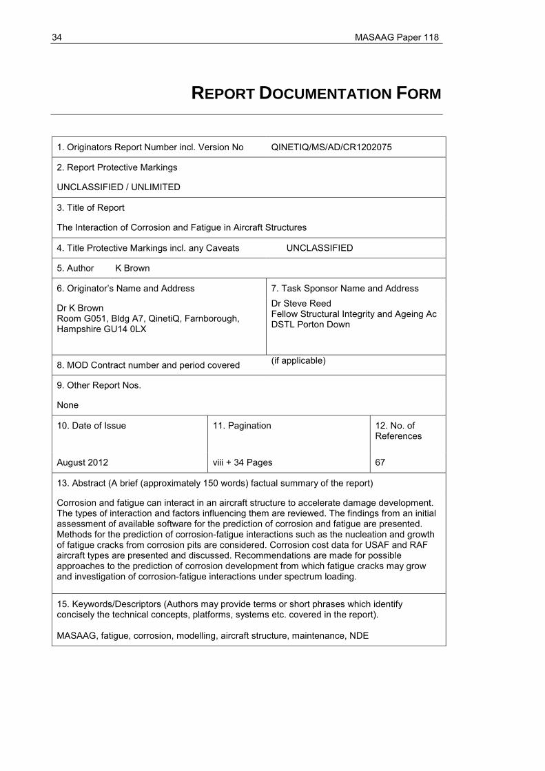
34 MASAAG Paper 118
REPORT DOCUMENTATION FORM
1. Originators Report Number incl. Version No
QINETIQ/MS/AD/CR1202075
2. Report Protective Markings
UNCLASSIFIED / UNLIMITED
3. Title of Report
The Interaction of Corrosion and Fatigue in Aircraft Structures
4. Title Protective Markings incl. any Caveats UNCLASSIFIED
5. Author K Brown
6. Originator’s Name and Address 7. Task Sponsor Name and Address
Dr K Brown Room G051, Bldg A7, QinetiQ, Farnborough, Hampshire GU14 0LX
Dr Steve Reed Fellow Structural Integrity and Ageing Ac DSTL Porton Down
8. MOD Contract number and period covered (if applicable)
9. Other Report Nos.
None
10. Date of Issue 11. Pagination 12. No. of References
August 2012 viii + 34 Pages 67
13. Abstract (A brief (approximately 150 words) factual summary of the report)
Corrosion and fatigue can interact in an aircraft structure to accelerate damage development. The types of interaction and factors influencing them are reviewed. The findings from an initial assessment of available software for the prediction of corrosion and fatigue are presented. Methods for the prediction of corrosion-fatigue interactions such as the nucleation and growth of fatigue cracks from corrosion pits are considered. Corrosion cost data for USAF and RAF aircraft types are presented and discussed. Recommendations are made for possible approaches to the prediction of corrosion development from which fatigue cracks may grow and investigation of corrosion-fatigue interactions under spectrum loading.
15. Keywords/Descriptors (Authors may provide terms or short phrases which identify concisely the technical concepts, platforms, systems etc. covered in the report).
MASAAG, fatigue, corrosion, modelling, aircraft structure, maintenance, NDE