the influence of soluble salts content on the performance
TRANSCRIPT

ISSN 1517-7076 articles e-12648, 2020
Autor Responsável: Camila Aparecida Zimmermann Data de envio: 13/11/2017 Data de aceite: 05/02/2020
10.1590/S1517-707620200002.1048
The influence of soluble salts content on the performance of an epoxy coating system via accelerated corrosion tests
Camila Aparecida Zimmermann
1,2, Luciano André Deitos Koslowski
3,
Maria Inês Siqueira Araújo1, Marcia Luciane Lange Silveira
1
1 Department of Chemical Engineering Joinville Campus – University of the Region of Joinville (UNIVILLE). Rua Paulo
Malschitzki, 10 - Zona Industrial Norte, CEP: 89219-710, Joinville, SC, Brazil. 2 Corrosion Laboratory, Innovation and Technology Department – Weg Tintas LTDA – BR 280, km 50, CEP: 89270-000,
Guaramirim, SC, Brazil. 3 Department of Civil Engineering Ibirama Campus – Santa Catarina State University (UDESC). Av. Getúlio Vargas
2822 - Bela Vista, CEP: 89140-000, Ibirama, SC, Brazil.
e-mail: [email protected], [email protected], [email protected], [email protected]
ABSTRACT
It is generally accepted that surpassing a threshold value of water-soluble salts at the substrate/coating inter-
face can impart premature failure in painted structures. The Coatings industry has an identified need in defin-
ing a maximum allowable soluble salts content, however, a variety of threshold values are found in published
data. Based on that, this work aims at evaluate the effect on epoxy coating performance of three different
ranges of soluble salts content taking into account the maximum allowable values specified by NORSOK M-
501 and IMO PSPC MSC.215, two important standards of naval and offshore sectors.
Blast-cleaned carbon steel specimens contaminated with sodium chloride solutions diluted in methanol rang-
ing 20, 50 and 100 mg/m² NaCl were painted with two epoxy-amine paint coats. Samples were evaluated by
cathodic disbondment, water immersion at 40 ºC, pull-off adhesion strength and cyclic corrosion tests.
Larger blisters and loss of adhesion were observed as the soluble salts content at the interface increased. Alt-
hough, it was not possible to find a critical level of soluble salts even considering data about similar coating
systems. A safe soluble salt content must be chosen based on tests that closer reproduce service and environ-
mental conditions to which a painted structure will be exposed.
Keywords: Carbon steel, Corrosion, Soluble Salts Content, Epoxy, Paint.
1. INTRODUCTION
Water-soluble salts, such as chlorides and sulphates, once deposited on steel structures will be hardly com-
pletely removed, even by abrasive blast-cleaning [1-3]. They are considered by the coatings industry all over
the world as responsible for the detriment of painted steel structures when a threshold concentration is ex-
ceeded [4-8].
The presence water-soluble salts at the metal/coating interface promotes osmosis due to their hygro-
scopic nature [5, 9, 10]. As water penetrates through the coating, that is a semi-permeable membrane, it dis-
solves the soluble salts resulting in a strong electrolyte that promotes underfilm corrosion [11-13]. Hence,
premature failures such as osmotic blistering, cathodic disbondment, adhesion loss, corrosion and delamina-
tion under the film are observed [6, 9, 13-15]. Even a coating with improved barrier characteristics to reduce
water diffusion may not be enough to stop corrosion from a contaminated substrate with soluble salts [10].
A big number of specifications and surface preparation procedures were developed trying to prevent
such premature failures resulting in a variety of different acceptable levels of soluble salts content [2-4, 16-
18]. An example is the Technical Report ISO/TR 15235, developed by the International Standard Organiza-
tion (ISO) that presents a collection of results from scientific works and data from coatings manufacturers
and users. According to this document, there is a wide variation in the existing knowledge regarding soluble
salts content and, its effects on the performance of coatings and related products [1]. Nowadays, the problem
remains unsolved since the coating industry did not define an acceptable soluble salt content or a global ref-

ZIMERMANN, C.A.; KOSLOWSKI, L.A.D.; ARAÚJO, M.I.S., et al. revista Matéria, v.25, n.2, 2020.
erence standard with levels that could be easily applied to reduce the risks of failure [4, 17, 18].
It is expected that different coatings systems behave equally different at various soluble salts levels
and exposure conditions [19]. In the best of our knowledge, however, there is no coherence for maximum
allowable soluble salts content even considering similar coating systems, with similar chemical binder, film
thickness, substrate and surface preparation. Consensus cannot be found even in worldwide standards for
coating systems approval. The standards IMO PSPC MSC.215 (82) [20] (naval sector) and the NORSOK M-
501 [21] (offshore sector) specify allowable soluble salts contents of 50 and 20 mg/m² NaCl, respectively.
Considering the published literature, for an epoxy system, which is one of the most important anticorrosion
coatings [22], with a dry film thickness within 200 to 300 μm, the soluble salts content considered of low risk
vary between <10 and 164 mg/m² NaCl [1, 15, 23, 24].
Lee et al. [23], for example, evaluated the effect of soluble salt contents within the range of 0 (virtual-
ly) up to 200 mg/m² NaCl on fully-blasted steel. They recommended a maximum soluble salts content of 100
mg/m² NaCl. Axelsen and Knudsen [24] carried out a study based on NORSOK M-501 [22]. They investi-
gated the effect of water-soluble salts on two commercially available epoxy systems and a clear lacquer in an
interval of 5 up to 300 mg/m² NaCl. On one hand, they showed that the soluble salts content had little effect
on the corrosion around the scribe in cyclic corrosion test and cathodic disbondment. On the other hand, the
authors concluded that the soluble salts content should be kept as low as possible and that the value proposed
by NORSOK M-501 is suitable. Moreover, Baek et. al [15] studied the effect on the performance of one
epoxy system from 0 (virtually) up to 660 mg/m² NaCl also based on the NORSOK M-501 [21] specifica-
tions. They settled a soluble salt limit of 115 mg/m² NaCl based on results of cyclic corrosion test, approxi-
mately 6 times higher than NORSOK M-501 recommended value.
Therefore, based on this diversity of values and ranges found in the literature, this work aims at inves-
tigate the influence of soluble salts content on the performance of a two-coat epoxy system applied on blast-
cleaned carbon steel based on the limits specified by IMO PSPC MSC.215 (82) [20] and NORSOK M-501
[21] standards and the technical report ISO/TR 15235 [1].
2. MATERIALS AND METHODS
2.1 Materials
Sodium chloride (NaCl, ≥99,0%, Anidrol) was used to prepare solutions for the contamination process, salt
spray and cathodic disbondment tests. Sodium sulphate (Na2SO4, ≥99,0%, Dinâmica Química) and sodium
carbonate (Na2CO3, ≥99,5%, Química Moderna) were used just in cathodic disbondment solution. Deionized
water was used in all experiments (MB 400 ion exchange resin, Purolite) if not mentioned otherwise.
2.2 Preparation of specimens for tests
2.2.1 Blast-cleaning
Steel panels were degreased with xylene and blasted with angular and spherical steel grit in the proportion
75:25 to Sa 2 ½ according to ISO 8501-1 [25]. A total of thirty-six specimens of (100 x 150 x 3) mm were
prepared for tests of soluble salts content, pull-off adhesion, cathodic disbondment and water immersion, and
other fifteen samples of (75 x 150 x 30) mm for cyclic corrosion test.
2.2.2 Contaminating procedure
The procedure for specimens’ contamination to achieve the proposed range of soluble salts was based on
method described by Flores et al. [26], Fuente et al. [7, 8, 27] e Baek et al. [15].
Three contamination ranges were selected to investigate the effects of soluble salts on steel before
painting. The condition A with a soluble salts level measured as sodium chloride up to 20 mg/m² was chosen
to evaluate the limit proposed by NORSOK M-501 [22]. The condition B, with a soluble salt level from 21
up to 50 mg/m² was selected to test the IMO PSPC MSC.215(82) [20] specification. And the condition C,
with a soluble salt content from 51 up to 100 mg/m² was selected trying to reproduce some of the highest
values mentioned by coating manufacturers according to ISO/TR 15235 [1].
Solutions for blast-cleaned specimens’ contamination were prepared by dissolving NaCl analytical
grade in 10 mL of deionized water in a beaker, at an amount previously weighed on analytical balance ac-
cording to the required solution concentration presented in Table 1. The soluble salt content generally found
on metal surface before the intentional contamination was not subtracted from the desired content as pre-tests
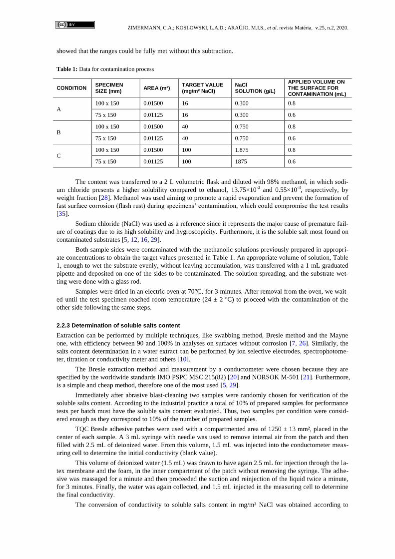
ZIMERMANN, C.A.; KOSLOWSKI, L.A.D.; ARAÚJO, M.I.S., et al. revista Matéria, v.25, n.2, 2020.
showed that the ranges could be fully met without this subtraction.
Table 1: Data for contamination process
CONDITION SPECIMEN SIZE (mm)
AREA (m²) TARGET VALUE (mg/m² NaCl)
NaCl SOLUTION (g/L)
APPLIED VOLUME ON THE SURFACE FOR CONTAMINATION (mL)
A 100 x 150 0.01500 16 0.300 0.8
75 x 150 0.01125 16 0.300 0.6
B 100 x 150 0.01500 40 0.750 0.8
75 x 150 0.01125 40 0.750 0.6
C 100 x 150 0.01500 100 1.875 0.8
75 x 150 0.01125 100 1875 0.6
The content was transferred to a 2 L volumetric flask and diluted with 98% methanol, in which sodi-
um chloride presents a higher solubility compared to ethanol, 13.75×10⁻³
and 0.55×10⁻³
, respectively, by
weight fraction [28]. Methanol was used aiming to promote a rapid evaporation and prevent the formation of
fast surface corrosion (flash rust) during specimens’ contamination, which could compromise the test results
[35].
Sodium chloride (NaCl) was used as a reference since it represents the major cause of premature fail-
ure of coatings due to its high solubility and hygroscopicity. Furthermore, it is the soluble salt most found on
contaminated substrates [5, 12, 16, 29].
Both sample sides were contaminated with the methanolic solutions previously prepared in appropri-
ate concentrations to obtain the target values presented in Table 1. An appropriate volume of solution, Table
1, enough to wet the substrate evenly, without leaving accumulation, was transferred with a 1 mL graduated
pipette and deposited on one of the sides to be contaminated. The solution spreading, and the substrate wet-
ting were done with a glass rod.
Samples were dried in an electric oven at 70°C, for 3 minutes. After removal from the oven, we wait-
ed until the test specimen reached room temperature (24 ± 2 ºC) to proceed with the contamination of the
other side following the same steps.
2.2.3 Determination of soluble salts content
Extraction can be performed by multiple techniques, like swabbing method, Bresle method and the Mayne
one, with efficiency between 90 and 100% in analyses on surfaces without corrosion [7, 26]. Similarly, the
salts content determination in a water extract can be performed by ion selective electrodes, spectrophotome-
ter, titration or conductivity meter and others [10].
The Bresle extraction method and measurement by a conductometer were chosen because they are
specified by the worldwide standards IMO PSPC MSC.215(82) [20] and NORSOK M-501 [21]. Furthermore,
is a simple and cheap method, therefore one of the most used [5, 29].
Immediately after abrasive blast-cleaning two samples were randomly chosen for verification of the
soluble salts content. According to the industrial practice a total of 10% of prepared samples for performance
tests per batch must have the soluble salts content evaluated. Thus, two samples per condition were consid-
ered enough as they correspond to 10% of the number of prepared samples.
TQC Bresle adhesive patches were used with a compartmented area of 1250 ± 13 mm², placed in the
center of each sample. A 3 mL syringe with needle was used to remove internal air from the patch and then
filled with 2.5 mL of deionized water. From this volume, 1.5 mL was injected into the conductometer meas-
uring cell to determine the initial conductivity (blank value).
This volume of deionized water (1.5 mL) was drawn to have again 2.5 mL for injection through the la-
tex membrane and the foam, in the inner compartment of the patch without removing the syringe. The adhe-
sive was massaged for a minute and then proceeded the suction and reinjection of the liquid twice a minute,
for 3 minutes. Finally, the water was again collected, and 1.5 mL injected in the measuring cell to determine
the final conductivity.
The conversion of conductivity to soluble salts content in mg/m² NaCl was obtained according to

ZIMERMANN, C.A.; KOSLOWSKI, L.A.D.; ARAÚJO, M.I.S., et al. revista Matéria, v.25, n.2, 2020.
Equation 1, from ISO 8502-9 [30]:
ρA = c.v. (γf – γi).100/A (1)
Where ρA: soluble salts content; c: empirical constant equal to 5 kg/m2.s
1 under normal conditions; v:
volume injected into the adhesive patch in millilitres; γf: final conductivity measurement of solution extracted
from the patch; γi: initial conductivity measured of deionized water (blank value); A: analysed area (corre-
sponding to the adhesive compartment area) in mm2.
The same steps were repeated for the three target contamination conditions.
2.2.4 Painting procedure
A coating system suitable for the proposed investigation was selected based on the specifications of coating
system 3B of NORSOK M-501 [21]. This is a coating system that acts only as a physical barrier specified for
application in ballast water carbon steel tanks, which is one of the most corrosive environments. The coating
system is detailed in Table 2.
Table 2: Coating system data
SUBSTRATE Steel hot rolled, ASTM A36-08 (Usiminas)
SURFACE PREPARATION Abrasive blast-cleaned at Sa 2 ½ [25]
ROUGHNESS PROFILE (µm) Between 50 and 80
MANUFACTURER Weg Tintas LTDA. (Guaramirim, Brazil)
FIRST COAT Primer-top coat epoxy amine two pack Grey N 6.5
NOMINAL DRY FILM THICKNESS – NDFT (µm) 150
SECOND COAT Primer-top coat epoxy amine two pack White N 9
NOMINAL DRY FILM THICKNESS – NDFT (µm) 150
Paints were prepared according to the manufacture’s technical datasheet. Both coats were applied with
a conventional spray gun (DeVilbiss JGA-503) respecting the overcoating period on both panels’ sides.
Seven days after the second coat application, the dry film thickness was measured with the magnetic-
type thickness gauge Tecnomedição SME-CII PLUS. A reduction factor of 25 μm was considered in each
measurement according to ISO 19840 [31] recommendation, as a roughened surface has a higher volume to
be completed when compared to a flat one.
The test side of each panel was selected based on measurements of dry film thickness (DFT) in five
points considering the acceptance criteria of ISO 19840 [31].
All specimens for the accelerated corrosion tests had their borders protected with the same applied
coating.
2.3 Tests
Tests were carried out according to the performance tests listed in the Table 3. All tests were carried out in a
laboratory at 23 ± 2 ºC and relative humidity of 55 ± 5%.
Table 3: Performance tests
TEST STANDARD PROCEDURE FOR TESTING
ESTIMATED LENGTH OF TIME (h)
DIMENSIONS OF SPECIMENS (mm)
NUMBER OF SPECIMENS PER CONDITION
Pull-off adhesion ISO 2812-2 [32] 24 100 x 150 x 3 1
Cathodic disbondment by impressed
current ISO 4624 [33] 720 100 x 150 x 3 3
Immersion in deionized water at 40° C ASTM G-8 [34] 3000 100 x 150 x 3 3
Cyclic corrosion ISO 20340 [35] 4200 75 x 150 x 3 3

ZIMERMANN, C.A.; KOSLOWSKI, L.A.D.; ARAÚJO, M.I.S., et al. revista Matéria, v.25, n.2, 2020.
Rusting and blistering grades eventually observed in accelerated corrosion tests were classified ac-
cording to standards ISO 4628-3 [36] and ISO 4628-2 [37], Tables 4 and 5, respectively.
Table 4: Rusting grade classification
DEGREE RUSTED AREA (%)
Ri 0 0
Ri 1 0.05
Ri 2 0.5
Ri 3 1
Ri 4 8
Ri 5 40 a 50
Table 5: Blistering grade classification
GRADE QUANTITY GRADE SIZE
0 None S0 Not visible under x 10 magnification
1 Very few S1 Only visible under magnification up to x 10
2 Few S2 Just visible with normal corrected vision
3 Moderate S3 Clearly visible with normal corrected vision (up to 0.5mm)
4 Considerable S4 0.5 to 5 mm
5 Dense S5 Larger than 5 mm
2.3.1 Pull-off adhesion test
Adhesion of a protective coating is an important prerequisite for corrosion protection effectiveness [22].
Dollies of 20 mm diameter were bonded with Scotch Weld epoxy adhesive DP-460 3M® on the spec-
imens’ surface. The coating and dollies surfaces were previously sanded with sandpaper grade 240. After the
epoxy adhesive curing of 24 h, the pull-off adhesion test was carried out with a hydraulic tester device
Positest AT-A applying a tensile stress rate of 1 MPa/s.
Failures percentage by type (adhesion/ cohesion) were determined according to ISO 4624 [33] as il-
lustrated in Figure 1, using the software DraftSight 2013 for area calculation.
Figure 1: Evaluation and classification of failure types developed in pull-off test. An adhesive failure is reported by a bar
between the letter that indicate the coats where the failure happened. A cohesive failure is reported by the coat letter
where the failure happened.
Source: Adapted from [38].
2.3.2 Cathodic disbondment by impressed current
The cathodic disbondment test is a powerful way to evaluate the synergic effect of cathodic protection and

ZIMERMANN, C.A.; KOSLOWSKI, L.A.D.; ARAÚJO, M.I.S., et al. revista Matéria, v.25, n.2, 2020.
the presence of soluble salts [23]. The explanation for the cathodic disbondment effect is unclear [24, 39]. It
is suggested that the integrity of the interaction between metal-polymer is compromised by pH increasing due
to the reactions 2 and 3 [12]:
In the anode:
Fe → Fe2+
+ 2 e- (2)
In the cathode, in non-aerated medium:
2 H2O + 2 e- → H2 + 2 OH
- (3)
The oxygen reduction reaction in the coating pores (reaction 2) and the migration of Na+ ions present
in the test solution leads to the accumulation of NaOH. Alkalinization can hydrolyses the interfacial bonds
between substrate/coating or even the paint itself, degrading it [40]. Another adverse effect is the generation
of hydrogen gas (reaction 2) arising the pressure and consequently causing disbondment [23].
The cathodic disbondment by impressed current was performed as mentioned in Table 3, by applying
a voltage between minus 1.378 to 1.478 V based on saturated calomel reference electrode (SCE). The voltage
was adjusted individually using potentiometers.
Specimens were prepared for test by performing a circular defect with a cutter up to the interface met-
al/coating, with initial diameter (di) of 7 mm, centred in relation to width and 50 mm from the bottom edge.
Specimens had 2/3 of their test area immersed in saline solution consisting of 1% by weight of sodium chlo-
ride, sodium sulphate and sodium carbonate in freshly potable water as recommended by ASTM G-8 [34].
After 30 days, the specimens were rinsed with potable water at ambient temperature and reconditioned
for 24 hours at 23 ± 2 ºC and relative humidity of 55 ± 5%, before detachment process.
To proceed with the delamination around the defect, four incisions were made crossed over the origi-
nal defect and the disbondment was conducted with a sharp, thin-bladed knife.
The equivalent circular diameter (ECD) in mm was calculated according to the equation 4 based on
ASTM G-8 [34].
ECD: ((At / (π/ 4))1/2
) - di (4)
The total area (At) detached was determined with the software DraftSight 2013.
2.3.3 Immersion in deionized water at 40 °C
Water immersion test is a common practice for accelerate adhesive failures and to estimate the blistering re-
sistance [16, 23].
Water immersion resistance test was carried out by immerging 2/3 of specimens’ length at an angle of
20 ± 5°, 3 cm apart from each other and from the walls, in a fiberglass tank (EQUILAM EQTI-120) made of
inert material. A submerged aquarium pump (Sarlo Better, SB1000a) was used for mechanical circulation at
a flow rate of 1000 L/h, maintained at 40 ± 1°C.
2.3.4 Cyclic corrosion test
The cyclic corrosion test combining saline fog and exposure to UV-A artificial weathering (340 nm) was
chosen because it provides the best correlation with the natural severe marine environment as already demon-
strated elsewhere [41]. Since it includes environmental variations such as wet and dry periods, with and
without UV rays, it is closer to what happens in the natural environment, without maintaining a corrosive
environment on a permanent basis [42].
Cyclic corrosion test was carried out complying with ISO 20340 [35], composed by:
72 hours of neutral salt spray, according to 9227 [43];
24 hours at -20 °C in a climatic chamber (ESPEC EPL-2H) and;
72 hours of accelerated weathering cycles complying with ISO 16474-3 [44], in a weathering
chamber (Q-LAB, model QUV/SE) with UV-A 340 nm lamps (Philips) of 40 W. One cycle consists of 4 h of
UV-A light at 60 °C and irradiance of 0.89 W/m² plus 4 h of condensation at 50°C.
Specimens received a scribe line made manually using a suitable scratcher and a metal ruler, immedi-
ately before starting test. The scribe line was made parallel to its short dimension, 25 mm far from one of the
ZIMERMANN, C.A.; KOSLOWSKI, L.A.D.; ARAÚJO, M.I.S., et al. revista Matéria, v.25, n.2, 2020.
short edges e 12.5 mm from the long edges, and 2 mm width.
After the exposure time, specimens were rinsed with potable water at ambient temperature and recon-
ditioned for 24 hours at 23 ± 2 ºC and relative humidity of 55 ± 5%, before detachment process using a sharp,
thin-bladed knife.
3. RESULTS
3.1 Soluble salts content
Soluble salts contents obtained by the Bresle extraction method and conductometer for the three conditions
proposed is presented on the Table 6.
Table 6: Soluble salts levels obtained after contamination of specimens
CONDITION TARGET OF SOLUBLE SALTS CONTENT (mg/m² NaCl)
SOLUBLE SALTS CONTENT AVERAGE (mg/m² NaCl)
A Up to 20 13.4 ± 0.8
B From 21 up to 50 48.4 ± 0.8
C From 51 up to 100 96.2 ± 8.1
The amounts of soluble salts attended the ranges proposed for comparative performance of test speci-
mens.
The soluble salt content measured immediately after surface preparation was 13.4 mg/m². To avoid
that the largest value of the proposed range for condition A (20 mg/m² NaCl) was extrapolated, an additional
surface contamination of the specimens belonging to this group was not carried out.
3.2 Pull-off adhesion test
Adhesion strength results and percentages of fractures types developed in the coating system are shown in
Table 7.
Table 7: Adhesion strength values and percentages per failure type
CONDITION DFT (µm) PULL-OFF STRENGTH
DOLLY 01 DOLLY 02 DOLLY 03
A 290 – 305 5.68 MPa
98.2% C/Y, 1.8% Y/Z
5.26 MPa
100% C/Y
5.17 MPa
0.4% B/C; 99.6% C/Y
B 285 – 305 10.66 MPa
100% C/Y
9.05 MPa
100% C/Y
9.69 MPa
100% C/Y
C 245 – 300 8.65 MPa
100% C/Y
8.81 MPa
0.2% A/B; 0.5% B/C;
99.3% C/Y
7.49 MPa
100% C/Y
Key: A: substrate; B: first coat; C: second coat; Y: glue; Z: dolly.
3.3 Cathodic disbondment by impressed current
The specimens’ assessments after the test ending are shown in Table 8.

ZIMERMANN, C.A.; KOSLOWSKI, L.A.D.; ARAÚJO, M.I.S., et al. revista Matéria, v.25, n.2, 2020.
Table 8: Results of cathodic disbondment test after 720 h
CONDITION DFT (µm) RUSTING DEGREE
BLISTERING DEGREE
ECD (mm) PULL-OFF STRENGTH AFTER TEST
A
310 – 355 Ri 0 0 (S0) 10.1 9.4 MPa
100% C/Y
265 – 330 Ri 0 0 (S0) 11.3 8.00 MPa
100% C/Y
270 – 330 Ri 0 0 (S0) 5.7 11.09 MPa
100% C/Y
B
285 – 310 Ri 0 0 (S0) 13.0 6.19 MPa
33.2% A/B; 66.8% C/Y
295 – 325 Ri 0 0 (S0) 12.7 5.14 MPa
91.1% A/B; 8.9% C/Y
300 – 330 Ri 0 0 (S0) 13.7 5.59 MPa
16.0% A/B; 84.0% C/Y
C
300 – 340 Ri 0 0 (S0) Total
disbondment
3.59 MPa
100% A/B
295 – 355 Ri 0 0 (S0) Total
disbondment
4.94 MPa
100% A/B
305 – 340 Ri 0 0 (S0) Total
disbondment
5.06 MPa
100% A/B
Key: A: substrate; B: first coat; C: second coat; Y: glue; Z: dolly.
Specimens for B and C conditions presented underfilm corrosion as shown in Figure 2, in regions of
adhesion failure and disbondment in the specimens, endorsing the development of subcutaneous oxidation in
the presence of chlorides.
Figure 2: Specimens 31a (condition A), 15a (condition B) and 3b (condition C), respectively after delamination around
the circular defect and the pull-off adhesion test.
3.4 Immersion in deionized water at 40 ºC
Table 9 shows the performance results of the test specimens obtained in the immersion test in deionized wa-
ter at 40 ºC.
The pull-off adhesion after immersion ending was not performed due to the high quantity of blisters
and consequent absence of a flat surface, as recommended by ISO 4624 [33].

ZIMERMANN, C.A.; KOSLOWSKI, L.A.D.; ARAÚJO, M.I.S., et al. revista Matéria, v.25, n.2, 2020.
Table 9: Results of specimens immersed in deionized water at 40°C for 480 hours
CONDITION DFT (µm) RUSTING DEGREE BLISTERING DEGREE
A
295 – 320 Ri 0 4 (S3)
300 – 330 Ri 0 4 (S3)
280 – 340 Ri 0 4 (S3)
B
275 – 310 Ri 0 3 (S5)
285 – 320 Ri 0 3 (S5)
295 – 340 Ri 0 3 (S5)
C
295 – 335 Ri 0 3 (S5)
255 – 305 Ri 0 4 (S5)
290 – 330 Ri 0 3 (S5)
Underfilm corrosion was observed after removing the paint film as shown in Figure 3.
Figure 3: Underfilm corrosion in specimens 32a (condition A), 18a (condition B) and 6b (condition C), respectively.
3.5 Cyclic corrosion test
The results of cyclic corrosion test are shown in Table 10.
Table 10: Cyclic corrosion test results after 4200 hours
CONDITION DFT (µm) RUSTING DEGREE
BLISTERING DEGREE
CORROSION AROUND THE SCRIBE (mm)
PULL-OFF STRENGTH
AFTER TEST
A
268 – 321 Ri 0 0 (S0) 11.83 9.84 MPa
100% C/Y
255 – 323 Ri 0 0 (S0) 11.65 9.64 MPa
100% C/Y
278 – 307 Ri 0 0 (S0) 15.53 9.24 MPa
100% C/Y
B
291 – 310 Ri 0 0 (S0) 15.15 6.75 MPa
100% C/Y
293 – 317 Ri 0 0 (S0) 13.83 7.15 MPa
100% C/Y
291 – 333 Ri 0 0 (S0) 14.49 8.60 MPa
100% C/Y
C
298 – 355 Ri 0 0 (S0) 16.03 6.60 MPa
36.5% A/B; 63.5% C/Y
301 – 360 Ri 0 0 (S0) 12.38 6.21 MPa
22.8% A/B; 77.2% C/Y
299 – 340 Ri 0 0 (S0) 17.35 9.68 MPa
21.6% A/B; 78.4% C/Y

ZIMERMANN, C.A.; KOSLOWSKI, L.A.D.; ARAÚJO, M.I.S., et al. revista Matéria, v.25, n.2, 2020.
Key: A: substrate; B: first coat; C: second coat; Y: glue; Z: dolly.
4. DISCUSSION
4.1 Soluble salts contents
An initial value of 13.4 mg/m² NaCl even before intentional contamination can be attributed to atmospheric
contaminants deposition on the surface of the test specimens prior to blasting, or even to steel grit used as
abrasives [1,44]. Abrasives themselves can contain salts at their sources, transport vessels, storage environ-
ments and so on, which contributes to the amount of soluble salts deposited on surface [45].
According to Appleman [14], dry abrasive blasting is only a mechanical technique incapable of re-
moving the microcrystals from the salts deposited in the steel. Johnson [46] explains that chloride ions form
strong electrochemical bonds with the metal surface, so it is difficult to extract them. Fuente et al. [7] states
that the percentage of soluble salts extraction from a dry sandblasted surface to the Sa 2 ½ degree is about
84%, i.e., this surface preparation method does not completely remove the present salts.
For the Condition (C), the sample standard deviation was relatively higher which can be ascribed to
some local accumulation of salts during the spreading of the contamination solution, or even by the blasting
process.
On one hand, the droplet and spreading method for laboratory contamination is the most convenient
and safe way to obtain pre-established levels of salts in a sample comparing to the exposure procedure in
natural weathering or corrosion test chamber, i.e., salt spray chambers [7, 47]. On the other hand, this method
provides crystal size and distribution less homogeneous than by spraying [19]. The slight deformation suf-
fered by some specimens during the blast-cleaning may have affected the spreading of the contamination
solution on the surface and contributed to a greater heterogeneity between the salt contents measured, as in
Condition C, with a larger standard deviation.
Moreover, the extraction method itself presents a considerably varied percentage of extraction, from
22 to 150%, according to literature data collected by Appleman [48], what could contribute to the variation in
the values collected, even though ISO 8502-6 [29] states that approximately 95% of soluble salts are satisfac-
torily dissolved by re-injecting the solvent into the compartment for just four times.
4.2 Pull-off adhesion test
Failures were predominantly of adhesive nature between the topcoat and the adhesive used to glue dollies. So,
the strength magnitude was not a response to the contamination level, just of the interaction/compatibility
between glue and paint, which fully corroborate with Lee et al. [23]. However, in Condition (C), it was ob-
served a small failure of type A/B (first coat/substrate), due to a likely accumulation of salts as explained
below.
The difference between the soluble salts levels did not affect the adhesion of the coating system. Ex-
posure to moisture and occurrence of osmosis are need so that the effects of salt contamination will be noted
[19, 44].
4.3 Cathodic disbondment by impressed current
Increasing the soluble salts content also raised the disbondment around the circular defect and the A/B (sub-
strate/ coating) failure percentage. As observed (Table 8) the adhesion strength decreased as the soluble salts
level increased, in agreement with Morcillo [6] and with the results of a linear tendency found by Axelsen
and Knudsen [24].
Based on cathodic disbondment results the maximum allowable salt contamination level for the coat-
ing system used might be within the range of approximately 13 to 50 mg/m² NaCl.
The presence of soluble contaminants increases the conductivity of the electrolyte in the region where
the paint is displaced, intensifying the reaction process with proportional decreasing of the adhesion and de-
lamination increasing [24].
There was water penetration through the film evidenced by the formation of underfilm corrosion, but
blistering was not observed because the hydraulic pressure caused by water was not enough to cause a per-
ceptible deformation in the bubble form. Although, Lee et al. [23] have observed blisters for all contamina-
tion ranges considering the results of “system C” like the one applied on the present work. Thus, even similar
paint systems can present anticorrosive performance completely different once blisters development is either

ZIMERMANN, C.A.; KOSLOWSKI, L.A.D.; ARAÚJO, M.I.S., et al. revista Matéria, v.25, n.2, 2020.
a response of paint viscoelasticity or its deformation mechanism [19].
4.4 Immersion in deionized water at 40 ºC
In the immersion test, unexpectedly all specimens showed blisters within 480 hours of test, ending it ahead of
scheduled. This behaviour can be explained by the high concentration gradient, elevated temperature and the
coating system porosity that facilitates water diffusion. The safe soluble salts content based on these results
might be lower than 13 mg/m² NaCl.
Lee et al. [23] observed failure of the epoxy coating system fully blasted only at 200 mg/m² NaCl in
immersion condition at 40 ºC, using natural seawater, after testing for 5 months. This completely different
performance compared to the results of this work can be easily explained by the concentration of salts in the
test media. Since osmosis happens due to a concentration gradient, a media like natural seawater that already
contains a salts concentration creates a smaller driven force than deionized water [16].
Low cross-linked regions in the paint film, even after the curing time specified by the manufacturer
may had become percolating pathways for water and O2 through the coating during test, as suggested for
Lyon et al. [10].
For Conditions B and C (Table 9), the blistering development in the same quantity and size suggests
that the formation rate for levels above 13 mg/m² NaCl is similar, in this case.
The barrier protection effect is clearly observed in the second specimen of condition C (Table 9), giv-
en the development of larger and bigger number of blisters in a smaller dry film thickness (255 – 305 μm)
when compared to the others of the same group (condition C).
Axelsen and Knudsen [24] found a defined time interval of 85, 60 and 5 days, respectively, for the develop-
ment of blistering between test specimens applied with clear epoxy and with contamination levels of approx-
imately 6, 40 and 127 mg/m² NaCl. Conversely, in this work blisters appeared at all levels of salt contents
within the inspection interval, between 14 and 20 days of testing. This fact suggests that the level of accepta-
ble contamination on a surface is particularly dependent of the coating formulation and its intrinsic polymeric
heterogeneity [9, 18]. Lee et al. [23] corroborate by concluding in their work that a reliable value of soluble
salt depends on applied coating system, environmental and substrate condition.
There are significant differences in the maximum allowable levels of soluble salts according to the da-
ta for two coats epoxy systems in water immersion tests presented by ISO/TR 15235 [1]. In table A.1 of this
standard, the level of soluble salts considered safe is 115 mg/m² NaCl. In Tables C.1 and C.2, nine of thirteen
coating manufacturers recommend values between 82 and 115 mg/m² NaCl, two other manufacturers up to
49 and only one up to 16 mg/m² NaCl. On the other hand, the results found in the present study shows that
there was a failure even at the lowest evaluated value, about 13.4 mg/m² NaCl.
Additionally, it is observed that the safety values recommended in these same tables for immersion
situations are lower, less than half to the levels indicated for structures exposed to atmospheric conditions,
probably due to the criticality of the immersion condition, as evidenced by this study and states by Tator [49].
4.5 Cyclic corrosion
Again, the corrosion around the scribe increased as soluble salts content also increased. But, underfilm corro-
sion affected the coating system adhesion just for the highest level considered in this study (100 mg/m² NaCl).
So, the allowable soluble salt content for this test might be between 50 and 100 mg/m² NaCl.
Axelsen and Knudsen [24] otherwise, reported that the salt content had little or no effect on coating
system with two coats of modified epoxy coating and a total coat thickness of 284 ± 35 μm, exposed in a
cyclic corrosion test.
The development of underfilm corrosion for condition C, is different of what was reported by Baek et
al. [15]. The authors did not observe this phenomenon in contaminated specimens with around 115 mg/m²
NaCl, exposed in cyclic corrosion test. In their study, the corrosion around the scribe was smaller than 3 mm,
within the contamination range mentioned above, contrasting our findings as shown in Table 10.
Lee at al. [23] have suggested the cathodic disbondment test is the most reliable way to find the max-
imum allowable soluble salt level. Nevertheless, it is more reasonable to expose a coating system to deter-
mine a permissible level based on tests that closely simulate the real service conditions. If a system will not
be used together with cathodic protection and it will be exposed in natural weathering conditions, the maxi-
mum allowable limit can be higher as discussed this work.

ZIMERMANN, C.A.; KOSLOWSKI, L.A.D.; ARAÚJO, M.I.S., et al. revista Matéria, v.25, n.2, 2020.
5. CONCLUSIONS
In the present study, we demonstrated that pull-off adhesion strength without any exposure to a corrosive
atmosphere, in order to promote osmosis, was not able to provide results in response to the levels of the sub-
strate contamination with soluble salts.
The results show that, for the coating system studied, NORSOK M-501 3B, a soluble salts content
above 20 mg/m² NaCl significantly compromises the performance in accelerated corrosion tests. In cathodic
disbondment and cyclic corrosion tests, adhesion failures due to water penetration and underfilm oxidation
occurred proportionally to the salt content used.
Considering the bibliographical survey carried out, as well as the results of this work, it was not pos-
sible to define a critical soluble salts content, satisfactory and safe, for different corrosive atmospheres to
which a painted steel structure may be exposed in service, even for an epoxy coating system worldwide stud-
ied on similar conditions of preparation and tests.
In addition, it is important to mention that different coating systems behave equally in a differentiated
manner on salts residues and exposure conditions. In this way, the choice and specification of a maximum
soluble salts content should be made with great caution, considering a test protocol as closer as possible to
the actual service conditions in which a coating system will be exposed.
The most recommended and safe practice is to work at the lowest soluble salt content as possible.
6. ACKNOWLEDGEMENTS
The authors are grateful to WEG Tintas Ltda and University of the Region of Joinville (UNIVILLE) for fi-
nancial assistance and scholarships at the beginning of the research.
7. BIBLIOGRAPHY
[1] ISO - INTERNATIONAL STANDARD ORGANIZATION. “ISO/TR 15235: Preparation of steel sub-
strates before application of paints and related products – Collected information on the effect of levels of
water-soluble salt contamination”, Switzerland, 2001.
[2] BATES, C. R., “Has the critical art of surface preparation for pipecoating been forgotten”, Journal of
Protective Coatings & Linings, v. 21, n. 8, pp. 26-34, Aug. 2004.
[3] MCKEEN, L. W., Fluorinated Coatings and Finishes Handbook, 2nd
ed., Oxford, England, Elsevier,
2016.
[4] JOHNSON, J. R., “soluble salts and specifications”, Coatings Pro Magazine, v.8, n. 2, pp. 2-6, Mar. 2008.
[5] FRANKHUIZEN, N., “Measuring NaCl, salt, and soluble contaminants with bresle patches – Part 1”,
Coatings & Linings, pp. 36-39, Nov. 2009.
[6] MORCILLO, M., “Soluble salts: their effect on premature degradation of anticorrosive paints”, Progress
in Organic Coatings, v. 36, pp. 137-147, 1999.
[7] FUENTE, D., CHICO, B., MORCILLO, M., “The effects of soluble salts at the metal/paint interface:
advances in knowlegde”, Portugaliae Electrochimica Acta, v. 24, pp. 191-206, 2006.
[8] FUENTE, D., BOHM, M., HOUYOUX, C., et al., “The settling of critical levels of soluble salts for
painting”, Progress in Organic Coatings, v. 58, pp. 23-32, 2007.
[9] FRANKHUIZEN, N., “Measuring NaCl, salt, and soluble contaminants with bresle patches – Part 2”,
Coatings & Linings, pp. 34-37, Dec. 2009.
[10] LYON, S. B., BINGHAM, R., MILLS, D. J., “Advances in corrosion protection by organic coatings:
what we know and what we’d like to know”, Progress in Organic Coatings, v. 102, Part A, pp. 2-7. Jan.
2017.
[11] NUNES, L. P. A., LOBO, C. O., Pintura Industrial na Proteção Anticorrosiva, 4th
ed., Rio de Janeiro,
Brazil, Interciência, 2012.
[12] GENTIL, V., Corrosão, 6th
ed., Rio de Janeiro, Brazil, LTC, 2012.
[13] FAZENDA, J. M. R. (Coord.), “Pintura de manutenção industrial”, In: Tintas & Vernizes: Ciência e
Tecnologia, 3th
ed., chapter 22, São Paulo, Brazil, Edgard Blücher, 2005.
[14] APPLEMAN, B. R., Painting over soluble salts: a perspective, Paint Square, 1987.

ZIMERMANN, C.A.; KOSLOWSKI, L.A.D.; ARAÚJO, M.I.S., et al. revista Matéria, v.25, n.2, 2020.
[15] BAEK, K. K., PARK, C. S., KIM, K. H., et al., “Effect of surface contaminants remained on the blasted
surface on epoxy coating performance and corrosion resistance”, Corrosion Science and Technology, v. 43, n.
25, pp. 27–32, 2006.
[16] SMITH, F. H., “Field joint coating of pipelines – effect of soluble salt contamination on 2-layer heat
shrink sleeve performance”, Anti-Corrosion Methods and Materials, v. 63, n. 2, pp. 105 – 115, 2016.
[17] STINER, H. “Soluble Salts and Coating Performance”, CORROSIONPEDIA,
https://www.corrosionpedia.com/soluble-salts-and-coating-performance/2/6502. Accessed in July 2017.
[18] Peters, H. “Salt Limits to Prevent Premature Coating Failures”, CORROSIONPEDIA,
https://www.corrosionpedia.com/2/4754/soluble-salts/salt-limits-to-prevent-premature-coating-failures. Ac-
cessed in July 2017.
[19] FUENTE, D., ROHWERDER, M., “Fundamental investigation on the stability of the steel/coating inter-
faces contaminated by submicroscopic salt particles”, Progress in Organic Coatings, v. 61, n. 2, pp. 233-239,
Feb. 2008.
[20] IMO - INTERNATIONAL MARITIME ORGANIZATION - MARITIME SAFETY COMMITTEE.
“IMO MSC.215 (82): Performance standard for protective coatings for dedicated seawater ballast tanks in all
types of ships and double-side skin spaces of bulk carriers”, United States of America, 2006.
[21] NORSOK STANDARD. “NORSOK M-501: Surface preparation and protective coating”, Norway, 2012.
[22] MÜLLER, B., POTH, U., Coatings Formulation: An International Textbook., 2nd
ed., Hanover, Germa-
ny, Vincentz, 2012.
[23] LEE, C.H., SON, S. M., BAEK, Y. H., KIM, D. Y., “Soluble salt criteria of epoxy coatings for ship’s
water ballast tank”, NACE International Corrosion Conference & Expo, 10017, San Antonio, Texas, United
States of America, 2010.
[24] AXELSEN, S. B., KNUDSEN, O. Ø., “The effect of water-soluble salt contamination on coating per-
formance”, NACE International Corrosion Conference & Expo, 11042, Dallas, Texas, United States of
America, Mar. 2011.
[25] ISO - INTERNATIONAL STANDARD ORGANIZATION. “ISO 8501-1: Preparation of steel sub-
strates before application of paints and related products - visual assessment of surface cleanliness -- part 1:
rust grades and preparation grades of uncoated steel substrates after overall removal of previous coatings”.
Switzerland, 2007.
[26] FLORES, S., SIMANCAS, J., MORCILLO, M., “Methods for samplings and analyzing soluble salts on
steel surfaces: a comparative study”, Paint Square, 1994.
[27] FUENTE, D., FLORES, S., MORCILLO, M., “Deterioration of paint systems applied on zinc substrates
contaminated with soluble salts”, Progress in Organic Coatings, v. 41, pp. 183-190, Feb. 2001.
[28] PINHO, S. P., MACEDO, E. A., “Solubility of NaCl, NaBr, and KCl in Water, Methanol, Ethanol, and
Their Mixed Solvents”, Journal of Chemical Engineering, v. 50, pp. 29-32, 2005.
[29] ISO - INTERNATIONAL STANDARD ORGANIZATION. “ISO 8502-6: Preparation of steel sub-
strates before application of paints and related products - Tests for the assessment of surface cleanliness --
Part 6: Extraction of soluble contaminants for analysis - The Bresle Method”. Switzerland, 2006.
[30] ISO - INTERNATIONAL STANDARD ORGANIZATION. “ISO 8502-9: Preparation of steel sub-
strates before application of paints and related products - Tests for the assessment of surface cleanliness --
Part 9: Field method for the conductometric determination of water - soluble salts”. Switzerland, 1998.
[31] ISO - INTERNATIONAL STANDARD ORGANIZATION. “ISO 19840 Paints and varnishes -- Corro-
sion protection of steel structures by protective paint systems -- Measurement of, and acceptance criteria for,
the thickness of dry films on rough surfaces”. Switzerland, 2012.
[32] ISO - INTERNATIONAL STANDARD ORGANIZATION. “ISO 2812-2: Paints and varnishes - De-
termination of resistance to liquids -- Part 2: Water immersion method”. Switzerland, 2007.
[33] ISO - INTERNATIONAL STANDARD ORGANIZATION. “ISO 4624: Paints and Varnishes – Pull off
test for adhesion”. Switzerland, 2002.
[34] ASTM - AMERICAN SOCIETY FOR TESTING AND MATERIALS. “ASTM G-8: Test Methods for
Cathodic Disbonding of Pipeline Coatings”. West Conshohocken, United States of America 1996.
[35] ISO - INTERNATIONAL STANDARD ORGANIZATION. “ISO 20340: Performance requirements for
protective paint systems for offshore and related structures”, Switzerland, 2009.

ZIMERMANN, C.A.; KOSLOWSKI, L.A.D.; ARAÚJO, M.I.S., et al. revista Matéria, v.25, n.2, 2020.
[36] ISO - INTERNATIONAL STANDARD ORGANIZATION. “ISO 4628-3: Paints and varnishes - Eval-
uation of degradation of coatings - Designation of quantity and size of defects, and of intensity of uniform
changes in appearance -- Part 3: Assessment of degree of rusting”, Switzerland, 2016.
[37] ISO - INTERNATIONAL STANDARD ORGANIZATION. “ISO 4628-2: Paints and varnishes - Eval-
uation of degradation of coatings - Designation of quantity and size of defects, and of intensity of uniform
changes in appearance -- Part 2: Assessment of degree of blistering”, Switzerland, 2016.
[38] DEFELSKO, http://www.defelsko.com/adhesion-tester/qa.htm. Accessed in June 2017.
[39] GREENFIELD, D., SCANTLEBURY, D., “The Protective action of organic coatings on steel: a review”,
The Journal of Corrosion Science and Engineering, v. 3. n. 5., Aug. 2000.
[40] MARTINEZ, S., ŽULJ, L. V., KAPOR, F., “Disbonding of underwater-cured epoxy coating caused by
cathodic protection current”. Corrosion Science, v. 51, n. 10, pp. 2253-2258, Oct. 2009.
[41] BOOCOCK, S., “Meeting industry needs for improved tests”, Journal of Protective Coatings & Linings,
pp. 70–76, 1995.
[42] QUILL, J., GAUNTNER, S., FOWLER, S., REGAN, J., “Combined corrosion and weathering: validat-
ing a concept with over a decade of research”, Q-lab Technical Article, LF-8160, 2013.
[43] ISO - INTERNATIONAL STANDARD ORGANIZATION. “ISO 9227: Corrosion tests in artificial
atmospheres -- Salt spray tests”, Switzerland, 2012.
[44] ISO - INTERNATIONAL STANDARD ORGANIZATION. “ISO 16474-3: Paints and varnishes --
Methods of exposure to laboratory light sources -- Part 3: Fluorescent UV lamps”. Switzerland, 2013.
[45] BORTAK, T. N., Guide to Protective Coatings: Inspection and Maintenance, United States of America,
United States Department of the Interior, 2002.
[46] JOHNSON, J. R., “Removing Soluble Salts”, Coatings Pro Magazine, v.8, n. 4, pp. 2-5, Jul. 2008.
[47] FUENTE, D., CHICO, B., MORCILLO, M., “Simulación en laboratorio mediante ensayos de corrosión
acelerada de la presencia y contenido en sales solubles en los productos de corrosión atmosférica del acero”,
Revista de Metalurgia, v. Extr., pp. 438-432, 2005.
[48] APPLEMAN, B. R., “Advances in Technology and Standards for Mitigating the Effects of Soluble
Salts”, Journal of Protective Coatings & Linings, v. 19, n. 5, pp. 42–47. May 2002.
[49] TATOR, K. B., “Soluble Salts and Coatings – An Overview - Part 1: A Summary of Recent Research on
Allowable Amounts of Salts Tolerated beneath Coatings”, Journal of Protective Coatings & Linings, v. 27, n.
2, pp. 50-63, Feb. 2010.
ORCID
Camila Aparecida Zimmermann http://orcid.org/0000-0001-9573-0900
Luciano André Deitos Koslowski http://orcid.org/0000-0003-2917-8681
Maria Inês Siqueira Araújo http://orcid.org/0000-0002-2157-5757
Marcia Luciane Lange Silveira http://orcid.org/0000-0003-4616-8645