the influence of elbow flexion and arm external rotation
TRANSCRIPT

The Influence of Elbow Flexion and ArmExternal Rotation on Peak Elbow Valgus
Torque and Ball Velocity in Baseball Pitching
by
L.W. Vliegen, BSc
in partial fulfilment of the requirements for the degree of
Master of Sciencein Mechanical Engineering
at the Delft University of Technology,to be defended publicly on Friday January 26, 2018 at 10:00 AM.
Student number: 4330862Master track: Biomechanical DesignSpecialization: Sports Engineering
Thesis committee: Prof. dr. H. E. J. Veeger TU Delft, supervisorDr. D. J. J. Bregman TU DelftDr. ir. A. J. Jansen TU Delft
An electronic version of this thesis is available at http://repository.tudelft.nl/.


The influence of elbow flexion and arm external rotation on peakelbow valgus torque and ball velocity in baseball pitching
Master thesis Liset Vliegen, TU Delft, Faculty of 3ME, Biomechanical Design
Abstract
Introduction Elbow injury, especially Ulnar Collateral Ligament (UCL) tear, is very common in base-ball pitching. This is often attributed to high valgus torques repetitively stressing the ligament. The goalof this study was to research the effect of Elbow Flexion (EF) and arm External Rotation (ER) angle onPeak Valgus Torque (PVT) as well as ball velocity, using a three-folded approach.
Methods Motion data of 12 Dutch A and AAA team pitchers were collected (29 pitches in total).Firstly, the relationships between the variables and outcomes were statistically evaluated with GeneralizedEstimating Equations (GEE). Secondly, simplified movements and EF and ER variations were input to atwo-segment model, which was based on the hypothesis that valgus torque is generated by inertial effectsfrom external rotation deceleration and forearm forward acceleration. Lastly, for one pitch per player, ERand EF angles were varied in simulations.
Results Statistical significance was only observed for higher EF as a predictor of increased PVT andhigher ER as a predictor of decreased ball velocity. In the two-segment model, PVT increased for higherEF and decreased for higher ER. The simulations showed different effects between pitchers, however, mosttrends were similar to those of the two-segment model. Ball velocity was maintained or increased withhigher EF, while the influence of ER on ball velocity differed between players.
Conclusion The two-segment model led to a more in-depth insight in the many factors influencingPVT in pitching. The results of this study suggest that higher ER and lower EF could lead to lower PVT,without necessarily giving in on performance. However, the results showed differences between pitchers. Asprevious studies reported opposite trends regarding ER, we believe that this discussion should be re-opened.Our findings suggest that some pitchers are more prone to elbow injury than others and that pitchers mightbe able to lower injury-risk by adapting their pitching technique.
1 Introduction
1.1 Background and research goalBaseball pitching is a highly dynamic movementthat shows high injury rates. In 1989-1999, 45% ofthe injured Major League Baseball (MLB) playerswere pitchers (Conte et al., 2001). In this study,22% of the playing loss days were because of elbowinjury. Another study reported that 26% of the 298youth pitchers experienced elbow pain, of which68% were on the medial side (Lyman et al., 2001).
A common elbow injury on the medial side is ul-nar collateral ligament (UCL) tear. A study among2500 professional baseball pitchers found that 16%had a history of UCL reconstruction (Conte et al.,2015). The incidence of UCL reconstructions isgrowing, especially in teenagers (Erickson et al.,2015). Even in asymptomatic players, abnormali-ties in the UCL have been observed (Kooima et al.,2004). For safe and injury-free pitching, researchinto elbow injury prevention is therefore very im-
portant.Elbow injury in pitching is often attributed to
high valgus torques. Valgus torque, which is com-monly encountered in pitching (Hariri and Safran,2010), is an external torque that the forearm ex-erts on the elbow joint, attempting to rotate theforearm to the lateral side with respect to the up-per arm. This movement is normally restrained bycounteracting internal varus torques, imparted onthe forearm by elbow joint structures, most notablythe UCL. The external valgus torque imparts a ten-sile force to the medial and a compressive force tothe lateral elbow structures. This can result notonly in injury to the medially located UCL, butalso to the medial muscles and ulnar nerve and indamage of the radiocapitellar joint on the lateralside (Safran et al., 2005; Cain et al., 2003). In fact,higher peak valgus torques were found in pitch-ers suffering from elbow injury and pitchers withabnormal UCL appearance than in asymptomaticpitchers (Anz et al., 2010; Hurd et al., 2011). Un-derstanding about how Peak Valgus Torque (PVT)
2

Figure 1: Two mechanisms can theoretically generate inter-nal varus torque in pitching: (1) rotational inertia and (2)translational inertia. The external valgus torque that theforearm exerts on the joint structures is equal to the inter-nal varus torque.
can be lowered, while keeping up high performancelevels, may help pitchers to prevent elbow injury.
Theoretically valgus torques in pitching can begenerated by two mechanisms (Figure 1): (1) ro-tational inertia: a resistance to angular acceler-ation/deceleration, leading to a torque; and (2)translational inertia: a resistance to linear accel-eration/deceleration results in an inertial force onthe center of mass (CoM), generating a torquearound the elbow joint. The magnitude of the val-gus torque depends on the posture of the body aswell as the accelerations and thus it is affected byadjusting pitching technique. This study focuseson the effect of humerothoracic External Rotation(ER) and Elbow Flexion (EF) angle, as they highlyinfluence the orientation of the forearm and hand.
Some studies have related these parameters tovalgus torque. Aguinaldo and Chambers (2009)and Sabick et al. (2004) reported that higherMaximum External Rotation (MER) correlatedwith higher PVT. Lower EF (a more extended el-bow) was reported to correlate with higher PVT(Aguinaldo and Chambers, 2009; Werner et al.,2002) and with higher risk at medial elbow pain(Huang et al., 2010). However, these correlationsdo not give any in-depth understanding on howhigh valgus torques develop as a result of the pitch-ing technique. In addition, the correlations do notnecessarily indicate causality and the effect can notbe extrapolated outside of the measured range ofthe data. These problems can be overcome by sim-ulations, controlling the specific variable of inter-est.
Moreover, higher MER and lower EF were alsoreported to correlate with ball velocity (Forten-
baugh et al., 2009; Huang et al., 2010), while theaforementioned studies did not correct for this, nordid they report correlations with ball velocity. Re-search on the influence of technique parameters onboth PVT and ball velocity is scarce. Therefore,the goal of this study was to thoroughly analyzehow humerothoracic external rotation and elbowflexion influence peak valgus torque and ball veloc-ity in baseball pitching.
First, a theoretical problem analysis is carriedout to form a hypothesis. Subsequently these hy-potheses are tested using pitching data from previ-ous studies, according to a three-folded approach:
1. Statistical analysis: do we find a significantrelationship between the variables and PeakValgus Torque and ball velocity in the data?
2. Two-segment model: simplifying the pitchingmovement to understand the mechanisms con-tributing to high valgus loads.
3. Simulations: tweaking the joint angles for allsubjects to research its influence on PVT andball velocity within the complex movement.
1.2 Analysis and hypothesisJoint torques and forces can be defined in the prox-imal or distal Segment Coordinate System (SCS)or projected onto Euler rotation axes. The upperarm (proximal) SCS does not rotate with elbowflexion, while we are interested in an expressionthat accounts for stress on medial and lateral el-bow structures in all flexion angles. The forearm(distal) SCS is irrelevant for the elbow as it rotateswith pronation/supination. Therefore, we definevalgus/varus torque as the projection of the nettorque vector on the floating 𝑋-axis perpendicu-lar to the plane spanned by the humerus 𝑍ℎ andthe ulnar 𝑌𝑢 axis from the respective segment co-ordinate systems (SCS) (Figure 2).
NB:The definition of the 𝑍ℎ axis in the humeralSCS is an estimation of the flexion-extensionaxis that cannot be assured to be equal tothe joint rotation axis. This may result inprojections of flexion/extension rotation/torqueon the varus/valgus or pro-/supination axis.
In pitching research, the pitching movement istypically divided into six phases, defined by five keyevents (Figure 3). The peak valgus torque (PVT)was reported to occur in the late cocking phase ofthe movement, just before Maximal External Ro-tation (MER) (Fleisig et al., 1995; Sabick et al.,2004; Werner et al., 1993). In this phase, we hy-
3

Figure 2: Floating 𝑥−axis for varus/valgus torque projec-tion: perpendicular to the humerus 𝑧ℎ and the ulnar 𝑦𝑢axes.
Figure 3: Six phases and five key events of the pitchingmovement (adapted from Fleisig et al. (1996)).
pothesize that valgus torque is mainly generatedby the following rotational inertia (1) and trans-lational inertia (2) mechanisms: (1) Before MER,the external rotation is slowed down by an internalrotation torque that shoulder joint structures exerton the upper arm. This gives the forearm an angu-lar deceleration, which results in an inertial valgustorque. (2) A forward acceleration of the forearm(from full body forward acceleration, thorax axialrotation and shoulder horizontal abduction) resultsin an inertial force on the center of mass (CoM),generating a valgus torque.
A higher arm External Rotation (ER) angle re-sults in a shorter moment arm with respect to (2),while it does not influence (1) provided that the an-gular accelerations are the same (Figure 4). There-fore, we hypothesize that higher ER leads to lowerPVT.
When the Elbow Flexion (EF) angle is close to90°, the shoulder internal/external rotation axis(𝑠2) and the elbow varus/valgus axis (𝑒2) align,leading to a maximum forearm valgus angular de-celeration induced by the internal rotation torque(1). Higher and lower EF angles change the di-rection of the varus/valgus axis, lowering the an-gular deceleration and thus lowering valgus torque(Figure 5). EF angle does not influence the mo-ment arm of the inertial force with respect to the
varus/valgus axis (2). However, forearm CoM ac-celeration (2) due to shoulder horizontal abductionand thorax axial rotation increases with elbow flex-ion as the distance to the rotation axes increases.
Figure 4: The hypothesized effects of External Rotation(ER) on the two mechanisms that generate valgus torque.
Figure 5: The hypothesized effects of Elbow Flexion (EF)on the two mechanisms that generate valgus torque.
2 Methods
2.1 Data collectionThe subjects of this study were eight right-handedpitchers from the Dutch AAA team (age: 16.3±0.7years, weight: 77.9±8.9 kg, length: 184.4±6.5 cm)and four right-handed pitchers from the Dutch Ateam (age: 28.3 ± 5.3 years, weight: 98.3 ± 4.6 kg,length: 193.3 ± 3.8 cm). The research project wasapproved by the Faculty of Human Movement Sci-ences’ local ethical committee and informed con-sent was signed by the participants and/or theirlegal tutor.
4

The pitchers were equipped with a full bodymarker set. In this study, the thorax and rightupper limb markers were used for kinematics anddynamics and the knee and ankle markers for phaseestimation. After a warm-up, they performedfive fastball pitches from a pitching mound. Themarker trajectories were recorded by a 10-camera(T40S, 100Hz) VICON system. The data wereinterpolated to correct for occlusions and filteredwith a 4th order Butterworth 12.5 Hz low-pass fil-ter. Based on the quality of the data, 29 pitches(1-3 pitches per player) could be used for this study.
2.2 Rigid body modelA rigid body model of the thorax and right up-per limb was used, based on the mean measuredlocal marker positions within each segment. TheSegment Coordinate Systems (SCS) and Joint Co-ordinate Systems (JCS) were based on ISB recom-mendations (Wu et al., 2002, 2005) (Appendix A).The ulnohumeral JCS was used for the elbow andthe humerothoracic JCS for the shoulder. Regres-sion equations from Dumas et al. (2007) were usedto determine the gleno-humeral joint position, thepositions of segment Centers of Mass (CoM) andthe segment masses and inertia matrices.
The right shoulder, elbow and wrist were mod-eled as spherical joints with 3 rotational degrees offreedom. The glenohumeral joint additionally had3 degrees of freedom to model the motion of thescapular girdle in a simplified way. The ball wasmodelled as a sphere with a 36.8mm radius anda weight of 145g, according MLB rules. The CoMwas assumed to be in the same position as the handCoM. Ball release was modelled as a 100% to 0%decreasing ball mass during the second half of theacceleration phase, approximated as 20 ms.
2.3 Kinematics and inverse dynam-ics
For kinematics and inverse dynamics, the wrenchand quaternion method as described by Dumaset al. (2004) was used. Quaternions are a repre-sentation of the segment attitude (alternative forthe rotation matrix R) that uses a vector and therotation around that vector. Wrench is a mechan-ical notation that represents forces and momentstogether in a 6D vector. These were all expressedin the inertial coordinate system (ICS), so thatno transformations between SCSs were necessary.This inverse dynamics method was used to deter-mine the net moments at the wrist, elbow and
shoulder in the ICS, using a distal to proximal se-quence. No external forces (except for gravity) acton the distal segment. The net moments at thejoints are calculated as the torque exerted by theproximal segment on the proximal end of the distalsegment.
Humerothoracic and elbow joint angles and tho-rax angles relative to the global coordinate systemare calculated according to the Euler angles definedby Wu et al. (2005) (Y-X-Y, Z-X-Y and Z-X-Y or-der respectively, Figure 6). Varus/valgus torque𝑀𝑒2
is defined as the projection of the net elbowtorque vector on the elbow floating rotation axis(e2) and it is calculated for every frame:
𝑀𝑒2= MICS
elbow ⋅ e2 (1)
NB: a positive 𝑀𝑒2elbow joint moment represents
an internal varus moment exerted on the forearm,or - as it is equal and opposite - an external val-gus moment loading the joint structures. Similarly,elbow flexion torque 𝑀𝑒1
is calculated as
𝑀𝑒1= MICS
elbow ⋅ e1 (2)
Similarly, this represents an internal elbow flexionmoment that is exerted on the forearm by the jointstructures.
Figure 6: Joint rotation axes for Euler angles and jointtorque projections.
2.4 Data processingThe pitch was subdivided in the six phases as cus-tomary in pitching research (Figure 3). The endof the wind-up phase (WU) was estimated usingthe highest point of the knee joint center of thestride leg. Foot contact (FC) was defined using theforward velocity of the stride leg ankle joint cen-ter (threshold 0.3 m/s). Maximum external andinternal rotation (MER and MIR) are the timesof minimum and maximum 𝑠3 Euler angle beforeand after ball release respectively. An estimation ofball velocity and the time of ball release (BR) wasmade using the maximum forward linear velocityof the middle finger distal interphalangeal marker(RHID3).
5
The mean and standard deviation between pitch-ers of the Elbow Flexion and External Rotation an-gle at the times of PVT and MER were calculated.Additionally, the mean and standard deviation ofthe forearm CoM forward acceleration was calcu-lated.
2.5 Statistical analysisThe linear relationship between the predictor (EF,ER) and the dependent variable (PVT, ball veloc-ity) was estimated using Generalized EstimatingEquations (GEE). GEE is a modeling of the mean(just as an ordinary regression analysis) that canaccount for multiple observations per subject: ob-servations are not assumed to be independent asa correlation structure between the observationsof the same subject are taken into account (Moenet al., 2016). The relationship is expressed in theform of 𝑦 = 𝑎+𝑏𝑥 and significance of the estimatedfactor 𝑏 is tested (𝑃 < 0.05).
2.6 Two-segment modelA simple two-segment model was made in MAT-LAB, consisting of an upper arm and a forearm-hand segment. Segment mass and length were de-fined as the averages of the subject data and theinertia and CoM properties were derived with re-gression equations from Dumas et al. (2007) (Table1). Only the cocking phase (Figure 3) was mod-elled. Thorax axial rotation was only taken intoaccount as a reference for shoulder angles, to cal-culate upper arm position.
Reference posture In all cases, the displace-ments and angles other than the defined movementsand variables (described below) were kept constantas in the following reference posture: the shoulderjoint stays at (0,0,0); the shoulder has 0° horizontalabduction, 80° abduction and 90° external rotation;the elbow has 90° flexion, 0° abduction and 100° ofpronation. This reference posture was based on theaverage values in the cocking phase of the subjectdata (Appendix C).
Movements The model was subjected to threesimple movements: (1) external rotation, (2) hori-zontal abduction and (3) acceleration. For (1) and(2), the input was the average shoulder joint angletime series of the total 29 pitches, relative to theglobal reference frame (assuming an upright, for-ward facing stationary thorax). For (3), the inputwas the average shoulder x- and z- displacementand the shoulder angles were defined relative to anaxially rotating thorax (average time series). In
the last simulation (4), the three movements werecombined.
Variables (Overview: Table 2) PVT depen-dency on Elbow Flexion was tested in two ways:constant and dynamic. Constant: EF was definedas a constant value, varying between 60° and 110°(5° steps). Dynamic: EF was the mean curve ±5-25° in 5° steps. In this case, the elbow startedextending before MER. External Rotation was var-ied using the mean curve ± 5-25° in 5° steps. Thecombined effect of EF and ER was lastly tested us-ing all possible combinations of the above EF andER values, for movement (4).
With the described input of angles and shouldercoordinates, the transformation matrices were cal-culated (Appendix B) and subsequently used forthe inverse dynamics calculations.
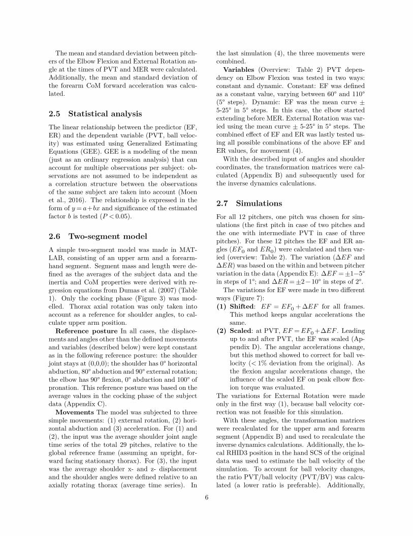
2.7 SimulationsFor all 12 pitchers, one pitch was chosen for sim-ulations (the first pitch in case of two pitches andthe one with intermediate PVT in case of threepitches). For these 12 pitches the EF and ER an-gles (𝐸𝐹0 and 𝐸𝑅0) were calculated and then var-ied (overview: Table 2). The variation (Δ𝐸𝐹 andΔ𝐸𝑅) was based on the within and between pitchervariation in the data (Appendix E): Δ𝐸𝐹 = ±1−5°in steps of 1°; and Δ𝐸𝑅 = ±2−10° in steps of 2°.
The variations for EF were made in two differentways (Figure 7):(1) Shifted: 𝐸𝐹 = 𝐸𝐹0 + Δ𝐸𝐹 for all frames.
This method keeps angular accelerations thesame.
(2) Scaled: at PVT, 𝐸𝐹 = 𝐸𝐹0 +Δ𝐸𝐹 . Leadingup to and after PVT, the EF was scaled (Ap-pendix D). The angular accelerations change,but this method showed to correct for ball ve-locity (< 1% deviation from the original). Asthe flexion angular accelerations change, theinfluence of the scaled EF on peak elbow flex-ion torque was evaluated.
The variations for External Rotation were madeonly in the first way (1), because ball velocity cor-rection was not feasible for this simulation.
With these angles, the transformation matriceswere recalculated for the upper arm and forearmsegment (Appendix B) and used to recalculate theinverse dynamics calculations. Additionally, the lo-cal RHID3 position in the hand SCS of the originaldata was used to estimate the ball velocity of thesimulation. To account for ball velocity changes,the ratio PVT/ball velocity (PVT/BV) was calcu-lated (a lower ratio is preferable). Additionally,
6
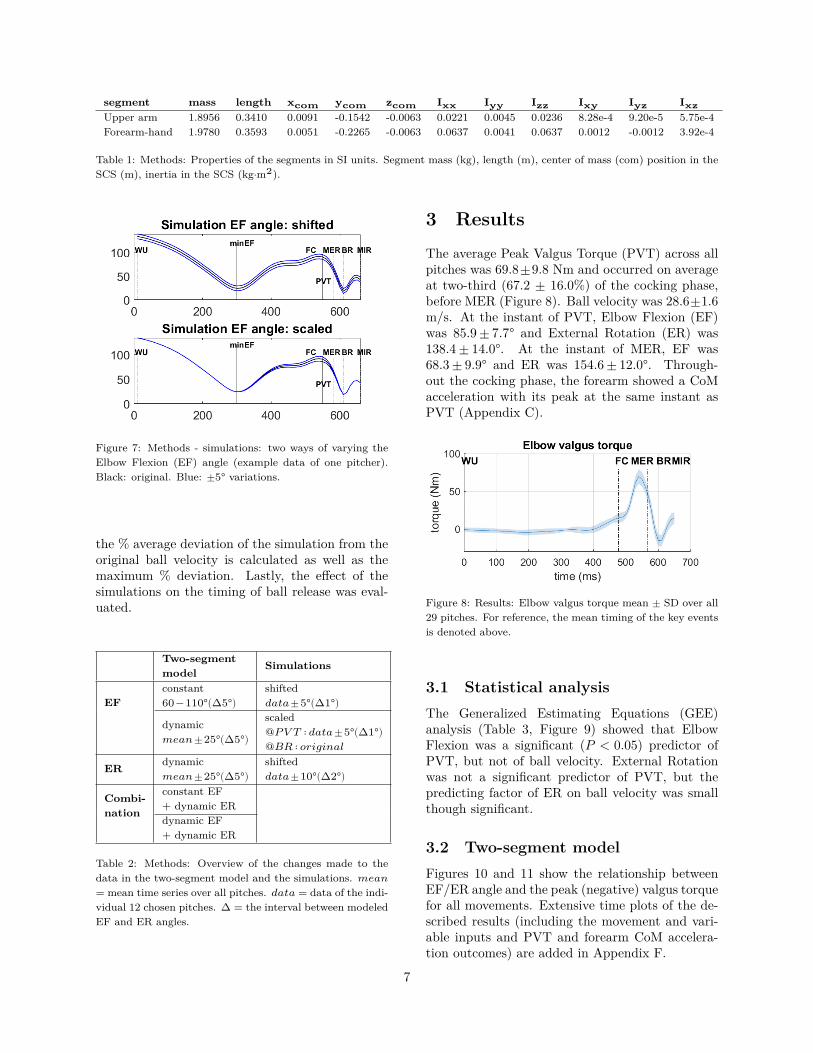
segment mass length 𝐱𝐜𝐨𝐦 𝐲𝐜𝐨𝐦 𝐳𝐜𝐨𝐦 𝐈𝐱𝐱 𝐈𝐲𝐲 𝐈𝐳𝐳 𝐈𝐱𝐲 𝐈𝐲𝐳 𝐈𝐱𝐳Upper arm 1.8956 0.3410 0.0091 -0.1542 -0.0063 0.0221 0.0045 0.0236 8.28e-4 9.20e-5 5.75e-4Forearm-hand 1.9780 0.3593 0.0051 -0.2265 -0.0063 0.0637 0.0041 0.0637 0.0012 -0.0012 3.92e-4
Table 1: Methods: Properties of the segments in SI units. Segment mass (kg), length (m), center of mass (com) position in theSCS (m), inertia in the SCS (kg⋅m2).
Figure 7: Methods - simulations: two ways of varying theElbow Flexion (EF) angle (example data of one pitcher).Black: original. Blue: ±5° variations.
the % average deviation of the simulation from theoriginal ball velocity is calculated as well as themaximum % deviation. Lastly, the effect of thesimulations on the timing of ball release was eval-uated.
Two-segmentmodel Simulations
EFconstant60−110°(∆5°)
shifted𝑑𝑎𝑡𝑎±5°(∆1°)
dynamic𝑚𝑒𝑎𝑛±25°(∆5°)
scaled@𝑃𝑉 𝑇 ∶ 𝑑𝑎𝑡𝑎±5°(∆1°)@𝐵𝑅 ∶ 𝑜𝑟𝑖𝑔𝑖𝑛𝑎𝑙
ER dynamic𝑚𝑒𝑎𝑛±25°(∆5°)
shifted𝑑𝑎𝑡𝑎±10°(∆2°)
Combi-nation
constant EF+ dynamic ERdynamic EF+ dynamic ER
Table 2: Methods: Overview of the changes made to thedata in the two-segment model and the simulations. 𝑚𝑒𝑎𝑛= mean time series over all pitches. 𝑑𝑎𝑡𝑎 = data of the indi-vidual 12 chosen pitches. ∆ = the interval between modeledEF and ER angles.
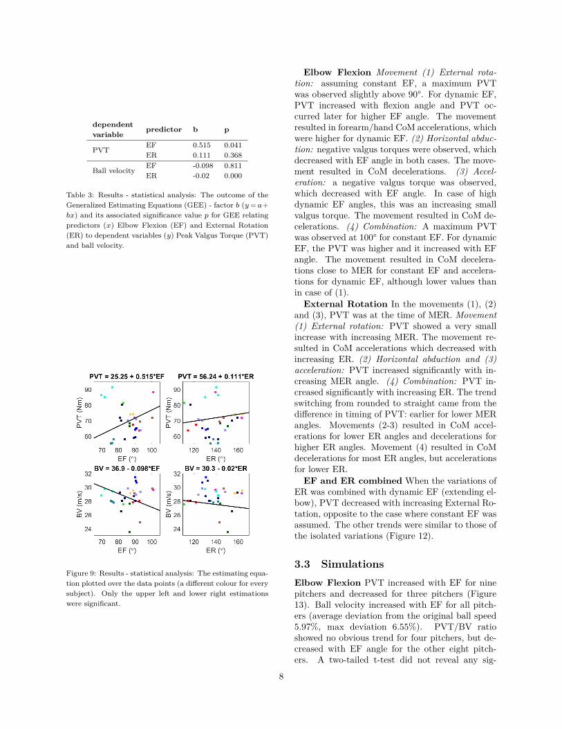
3 ResultsThe average Peak Valgus Torque (PVT) across allpitches was 69.8±9.8 Nm and occurred on averageat two-third (67.2 ± 16.0%) of the cocking phase,before MER (Figure 8). Ball velocity was 28.6±1.6m/s. At the instant of PVT, Elbow Flexion (EF)was 85.9 ± 7.7° and External Rotation (ER) was138.4 ± 14.0°. At the instant of MER, EF was68.3 ± 9.9° and ER was 154.6 ± 12.0°. Through-out the cocking phase, the forearm showed a CoMacceleration with its peak at the same instant asPVT (Appendix C).
Figure 8: Results: Elbow valgus torque mean ± SD over all29 pitches. For reference, the mean timing of the key eventsis denoted above.
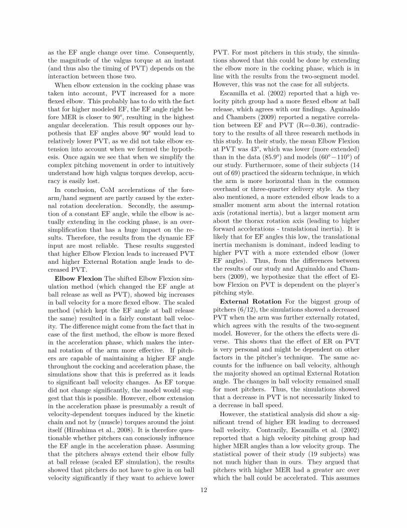
3.1 Statistical analysisThe Generalized Estimating Equations (GEE)analysis (Table 3, Figure 9) showed that ElbowFlexion was a significant (𝑃 < 0.05) predictor ofPVT, but not of ball velocity. External Rotationwas not a significant predictor of PVT, but thepredicting factor of ER on ball velocity was smallthough significant.
3.2 Two-segment modelFigures 10 and 11 show the relationship betweenEF/ER angle and the peak (negative) valgus torquefor all movements. Extensive time plots of the de-scribed results (including the movement and vari-able inputs and PVT and forearm CoM accelera-tion outcomes) are added in Appendix F.
7
dependentvariable predictor b p
PVT EF 0.515 0.041ER 0.111 0.368
Ball velocity EF -0.098 0.811ER -0.02 0.000
Table 3: Results - statistical analysis: The outcome of theGeneralized Estimating Equations (GEE) - factor 𝑏 (𝑦 = 𝑎+𝑏𝑥) and its associated significance value 𝑝 for GEE relatingpredictors (𝑥) Elbow Flexion (EF) and External Rotation(ER) to dependent variables (𝑦) Peak Valgus Torque (PVT)and ball velocity.
Figure 9: Results - statistical analysis: The estimating equa-tion plotted over the data points (a different colour for everysubject). Only the upper left and lower right estimationswere significant.
Elbow Flexion Movement (1) External rota-tion: assuming constant EF, a maximum PVTwas observed slightly above 90°. For dynamic EF,PVT increased with flexion angle and PVT oc-curred later for higher EF angle. The movementresulted in forearm/hand CoM accelerations, whichwere higher for dynamic EF. (2) Horizontal abduc-tion: negative valgus torques were observed, whichdecreased with EF angle in both cases. The move-ment resulted in CoM decelerations. (3) Accel-eration: a negative valgus torque was observed,which decreased with EF angle. In case of highdynamic EF angles, this was an increasing smallvalgus torque. The movement resulted in CoM de-celerations. (4) Combination: A maximum PVTwas observed at 100° for constant EF. For dynamicEF, the PVT was higher and it increased with EFangle. The movement resulted in CoM decelera-tions close to MER for constant EF and accelera-tions for dynamic EF, although lower values thanin case of (1).
External Rotation In the movements (1), (2)and (3), PVT was at the time of MER. Movement(1) External rotation: PVT showed a very smallincrease with increasing MER. The movement re-sulted in CoM accelerations which decreased withincreasing ER. (2) Horizontal abduction and (3)acceleration: PVT increased significantly with in-creasing MER angle. (4) Combination: PVT in-creased significantly with increasing ER. The trendswitching from rounded to straight came from thedifference in timing of PVT: earlier for lower MERangles. Movements (2-3) resulted in CoM accel-erations for lower ER angles and decelerations forhigher ER angles. Movement (4) resulted in CoMdecelerations for most ER angles, but accelerationsfor lower ER.
EF and ER combined When the variations ofER was combined with dynamic EF (extending el-bow), PVT decreased with increasing External Ro-tation, opposite to the case where constant EF wasassumed. The other trends were similar to those ofthe isolated variations (Figure 12).
3.3 SimulationsElbow Flexion PVT increased with EF for ninepitchers and decreased for three pitchers (Figure13). Ball velocity increased with EF for all pitch-ers (average deviation from the original ball speed5.97%, max deviation 6.55%). PVT/BV ratioshowed no obvious trend for four pitchers, but de-creased with EF angle for the other eight pitch-ers. A two-tailed t-test did not reveal any sig-
8

(a) 1. External rotation (b) 2. Horizontal abduction (c) 3. Forward translation (d) 4. Combined
Figure 10: Results - two-segment model: plots of the Elbow Flexion (EF) angle (x-axis) versus the Peak Valgus Torque (PVT)(y-axis) for four movements. Black: contant EF. Blue: dynamic EF (EF value at 2/3 of cocking phase plotted).
(a) 1. External rotation (b) 2. Horizontal abduction (c) 3. Forward translation (d) 4. Combined
Figure 11: Two-segment model: Plots of the simulated Maximal External Rotation (MER) angle (x-axis) versus the PeakValgus Torque (PVT) (y-axis) for four movements.
Figure 12: Results - two-segment model: 3D plot of the com-bined effect of Elbow Flexion (EF) and Maximal ExternalRotation (MER) angle. Black: constant EF. Blue: dynamicEF (EF value at 2/3 of cocking phase plotted).
nificant differences between the baseline data ofthe increasing/decreasing PVT groups (team, age,weight, height and range of motion).
The scaled EF simulations showed a ball veloc-ity close to the original pitches (average deviation0.49%, maximum deviation 0.75%). PVT increasedwith EF angle for nine pitchers, decreased for onepitcher and showed no obvious trend for two pitch-ers (Figure 14). PVT/BV ratio increased with EFfor three and decreased for three pitchers. For onepitcher, the elbow flexion torque increased due tothe simulation method. For the other eleven pitch-ers, only slight increases or decreases were observed(Appendix D). The timing of ball release was notaffected by the simulations.
External Rotation Patterns of ER vs. PVTwere very inconsistent between pitchers (Figure15). The biggest group (six out of twelve pitch-ers) showed a decreasing PVT for higher ER. Forfour pitchers, PVT showed a maximum, but at dif-ferent ER angles. PVT increased with higher ERfor two pitchers. Ball velocity showed an optimalER angle for eight pitchers, although at differentvalues. Two pitchers showed unclear relationships,for one pitcher ball velocity increased and for oneit decreased with ER. Ball velocity deviated fromthe original pitch with a mean of 2.46% and a maxof 4.85%. PVT/BV ratio decreased with ER for
9

Figure 13: Results - simulations: shifted Elbow Flexion (EF): effect of EF (value at original time of PVT) on Peak ValgusTorque (PVT), ball velocity and PVT/BV ratio. Each color represents simulated values for one pitcher.
Figure 14: Results - simulations: scaled Elbow Flexion (EF): effect of EF (value at original time of PVT) on Peak ValgusTorque (PVT), ball velocity and PVT/BV ratio. Each color represents simulated values for one pitcher.
six pitchers, showed only small deviations for fourpitchers and showed unclear trends for 2 pitchers.Two separate clouds arose: low ER/low ratio andhigh ER/high ratio. A two-tailed t-test did notreveal any significant differences in baseline data(team, age, weight, height and range of motion)between the two groups. The timing of ball re-lease was not affected for ten pitchers, but for onepitcher it occurred 10 ms earlier (red plots) and forone pitcher 20 ms earlier (black plots) for some ERvariations (both higher and lower ER variations).
4 Discussion
4.1 ResultsThe high incidence of elbow injury, especially tothe UCL, has been linked to recurring high valgustorques occurring in the late cocking phase of thepitching movement. This study was carried out inorder to investigate how Elbow Flexion (EF) andarm External Rotation (ER) variations affect PeakValgus Torque (PVT) and whether they also influ-ence ball velocity.
In the data, an average PVT of 69.8 Nm occurredat 67% of the cocking phase. An average ball ve-locity of 28.6 m/s (64.0 mph) was observed. The
statistical analysis (Generalized Estimating Equa-tions, GEE) showed that PVT increased signifi-cantly with a greater Elbow Flexion angle, whileits effect on ball velocity was not significant. Theeffect of External Rotation on PVT was not signif-icant, but ball velocity showed a slight but signifi-cant decrease for a further externally rotated arm.The two-segment model showed that the influenceof EF and ER on PVT was different when the el-bow extension at the end of the cocking phase wasmodeled, compared to the case where the EF anglewas assumed constant. Taking the elbow extensioninto account, PVT increased for a more flexed el-bow (higher EF) and a less externally rotated arm(lower ER). The results of the simulations indicatedthat the effect of EF and ER on PVT differs be-tween pitchers. By keeping the EF angle at ballrelease the same as in the original data, ball ve-locity was kept nearly constant (< 1% change). Inthis case, PVT increased with greater elbow flex-ion. A narrow majority of the pitchers showed de-creasing PVT for higher External Rotation, whileno pattern was found in the effect on ball veloc-ity. The conclusions from the three methods aresummarized in Table 4.
The average peak valgus torque of 69.8 Nm calcu-lated from the original data is similar to literature
10

Figure 15: Results - simulations: effect of External Rotation (value at original time of PVT) on Peak Valgus Torque (PVT),ball velocity and PVT/BV ratio. Each color represents simulated values for one pitcher.
EF ER
PVTstatistics + (sig.) +two-segment + −simulations diff/+ diff/−
BVstatistics − − (sig.)two-segment n.a. n.a.simulations +/0 diff
Table 4: Overview of the results from the statistical analysis(GEE), two-segment model and simulations. + indicatesa positive relationship, − a negative relationship and 0 no(clear) relationship. sig. = significance in the GEE; diff =different relationships among the subjects in the simulations;n.a. = not applicable (not modeled).
values, which are usually reported around 50-65Nm for adult pitchers (Aguinaldo and Chambers,2009; Fleisig et al., 1995; Gasparutto et al., 2016;Matsuo et al., 2006). Previous research agreedwith our finding that PVT occurred in the lastpart of the cocking phase, but the timing in thisstudy was slightly earlier than previously reported:67% of the cocking phase versus approximately 75%or later (Fleisig et al., 1995; Werner et al., 1993;Sabick et al., 2004; Zheng et al., 2004).
Ball velocity was estimated by the peak forwardvelocity of the RHID3 marker as 28.6 m/s (64.0mph) on average. However, baseline data showedan average of 35.8 m/s (80 mph). The discrepancycould result from two issues. First of all, in mostcases the ball is not thrown precisely along the for-ward direction. However, this method was chosenbecause it leaves out finger movements that mighthave a high velocity in a different direction than theball. Second of all, the relatively low frequency ofthe data acquisition could have cut off high velocitypeaks.
Two-segment model: evaluation To analyzehow high valgus torques develop, the two-segmentmodel was used. It was based on the hypothe-sis that valgus torque is generated by inertial ef-
fects from external rotation angular decelerationand forearm forward acceleration. Forearm for-ward acceleration was assumed to be resulting fromshoulder displacement, thorax axial rotation andshoulder horizontal abduction.
The modeled movements (2 and 3) that didnot include external rotation showed a decelerat-ing forearm CoM close to MER. When externalrotation was applied (movements 1 and 4), theforearm CoM accelerated, as it did in the origi-nal data. At first glance, this opposes our intu-ition, as external rotation brings the forearm fur-ther backward. However, this external rotationis decelerated, which leads to a net forearm/handCoM acceleration. Thus, although valgus torqueis indeed partly generated by inertial effects fromforearm forward acceleration, our problem analysisdid not describe the complete mechanism. Apartfrom thorax rotations, shoulder displacement (fromfull body accelerations) and horizontal abduction,forearm CoM acceleration is also caused by exter-nal rotation deceleration.
Additionally, we modeled the elbow flexion an-gle in two ways: constant (90°) and dynamic (ex-tending before MER). In the case of constant EF,we found forearm CoM deceleration close to MER,while the results assuming an extending elbow aswell as the original data showed accelerations. In-deed, when the arm is externally rotated more than90°, elbow extension brings the forearm forward.Thus, elbow extension acceleration leads to fore-arm CoM forward acceleration. The constant el-bow flexion angle therefore appeared to be an over-simplification. Consistently, the curve of valgustorque over time resembled the actual data morewhen elbow extension was modeled. As explainedin the problem analysis (Figure 5), the projection ofExternal Rotation deceleration on the valgus axisdepends on the EF angle. In the cocking phase,the values of that ER angular deceleration as well
11
as the EF angle change over time. Consequently,the magnitude of the valgus torque at an instant(and thus also the timing of PVT) depends on theinteraction between those two.
When elbow extension in the cocking phase wastaken into account, PVT increased for a moreflexed elbow. This probably has to do with the factthat for higher modeled EF, the EF angle right be-fore MER is closer to 90°, resulting in the highestangular deceleration. This result opposes our hy-pothesis that EF angles above 90° would lead torelatively lower PVT, as we did not take elbow ex-tension into account when we formed the hypoth-esis. Once again we see that when we simplify thecomplex pitching movement in order to intuitivelyunderstand how high valgus torques develop, accu-racy is easily lost.
In conclusion, CoM accelerations of the fore-arm/hand segment are partly caused by the exter-nal rotation deceleration. Secondly, the assump-tion of a constant EF angle, while the elbow is ac-tually extending in the cocking phase, is an over-simplification that has a huge impact on the re-sults. Therefore, the results from the dynamic EFinput are most reliable. These results suggestedthat higher Elbow Flexion leads to increased PVTand higher External Rotation angle leads to de-creased PVT.
Elbow Flexion The shifted Elbow Flexion sim-ulation method (which changed the EF angle atball release as well as PVT), showed big increasesin ball velocity for a more flexed elbow. The scaledmethod (which kept the EF angle at ball releasethe same) resulted in a fairly constant ball veloc-ity. The difference might come from the fact that incase of the first method, the elbow is more flexedin the acceleration phase, which makes the inter-nal rotation of the arm more effective. If pitch-ers are capable of maintaining a higher EF anglethroughout the cocking and acceleration phase, thesimulations show that this is preferred as it leadsto significant ball velocity changes. As EF torquedid not change significantly, the model would sug-gest that this is possible. However, elbow extensionin the acceleration phase is presumably a result ofvelocity-dependent torques induced by the kineticchain and not by (muscle) torques around the jointitself (Hirashima et al., 2008). It is therefore ques-tionable whether pitchers can consciously influencethe EF angle in the acceleration phase. Assumingthat the pitchers always extend their elbow fullyat ball release (scaled EF simulation), the resultsshowed that pitchers do not have to give in on ballvelocity significantly if they want to achieve lower
PVT. For most pitchers in this study, the simula-tions showed that this could be done by extendingthe elbow more in the cocking phase, which is inline with the results from the two-segment model.However, this was not the case for all subjects.
Escamilla et al. (2002) reported that a high ve-locity pitch group had a more flexed elbow at ballrelease, which agrees with our findings. Aguinaldoand Chambers (2009) reported a negative correla-tion between EF and PVT (R=-0.36), contradic-tory to the results of all three research methods inthis study. In their study, the mean Elbow Flexionat PVT was 43°, which was lower (more extended)than in the data (85.9°) and models (60°−110°) ofour study. Furthermore, some of their subjects (14out of 69) practiced the sidearm technique, in whichthe arm is more horizontal than in the commonoverhand or three-quarter delivery style. As theyalso mentioned, a more extended elbow leads to asmaller moment arm about the internal rotationaxis (rotational inertia), but a larger moment armabout the thorax rotation axis (leading to higherforward accelerations - translational inertia). It islikely that for EF angles this low, the translationalinertia mechanism is dominant, indeed leading tohigher PVT with a more extended elbow (lowerEF angles). Thus, from the differences betweenthe results of our study and Aguinaldo and Cham-bers (2009), we hypothesize that the effect of El-bow Flexion on PVT is dependent on the player’spitching style.
External Rotation For the biggest group ofpitchers (6/12), the simulations showed a decreasedPVT when the arm was further externally rotated,which agrees with the results of the two-segmentmodel. However, for the others the effects were di-verse. This shows that the effect of ER on PVTis very personal and might be dependent on otherfactors in the pitcher’s technique. The same ac-counts for the influence on ball velocity, althoughthe majority showed an optimal External Rotationangle. The changes in ball velocity remained smallfor most pitchers. Thus, the simulations showedthat a decrease in PVT is not necessarily linked toa decrease in ball speed.
However, the statistical analysis did show a sig-nificant trend of higher ER leading to decreasedball velocity. Contrarily, Escamilla et al. (2002)reported that a high velocity pitching group hadhigher MER angles than a low velocity group. Thestatistical power of their study (19 subjects) wasnot much higher than in ours. They argued thatpitchers with higher MER had a greater arc overwhich the ball could be accelerated. This assumes
12

that when the MER angle changes, the ER angleat ball release remains the same, while our simu-lations assumed a shift of that arc. Clearly, theangle as well as angular acceleration play a role,but it is unclear whether the MER angle and therange of ER in the acceleration phase are really re-lated. Thus, the effect of ER on ball velocity is stilldebated.
Aguinaldo and Chambers (2009) and Sabicket al. (2004) reported positive correlations betweenMER and PVT (R=0.55 and R=0.65), indicatingthat high MER could be harmful. Their findings donot agree with the results of our two-segment modeland simulations. First of all, Aguinaldo et al. andSabick et al. did not correct for ball velocity. Theirsubjects with higher MER might also have experi-enced a higher ball velocity. Secondly, in our mod-els, we kept the angular accelerations of ER thesame as in the original data. Subjects in their stud-ies who showed higher MER might have also experi-enced a higher External Rotation deceleration - anexpected effect if they started externally rotatingfrom a similar starting position (which is not cer-tain). The authors of these studies did not presentany thought on why PVT could have increased withincreasing MER. Aguinaldo and Chambers even re-garded it as an expected trend - ”... higher shoulderexternal rotation is expected to increase elbow val-gus”, while referring to the previously mentionedstudy of Sabick et al. and an article by Fleisig et al.(1995). Although Fleisig’s work, relating pitchingbiomechanics to upper extremity injury, is an im-portant piece in pitching literature, this is an unjustreference as the article does not mention anythingabout the role of MER angle on valgus torque orelbow injury. Following the results of our study, webelieve that this discussion should be re-opened.
4.2 LimitationsTwo-segment model In the previous parts of thispaper, we discussed the trends of PVT in the two-segment model, but we did not refer to the absolutePVT values. The reason for this is that these val-ues were not realistic, due to some movements be-ing suppressed in the model for simplification pur-poses. Although the absolute PVT values were notrealistic, the results of the two-segment model werestill valuable in terms of analyzing the trends.
An important example of a suppressed movementis the elbow valgus rotation. Non-zero valgus an-gles were found in the data, but not input to themodel. Therefore, the internal joint torques turnout higher. As a matter of fact, no such valgus
rotation is actually happening in the joint, this ismerely a result of the simplification of the rotationaxes of the elbow. It assumes a perfectly outlinedhinge, which is not the case in reality. The abduc-tion angle is a projection of the carrying angle thatchanges with elbow flexion (Van Roy et al., 2005).Furthermore, as mentioned in the introduction, therough estimation of the flexion axis might have ledto projection of flexion/extension rotations on thevalgus axis.
For most pitchers, we saw that the trends in theresults of the two-segment model agreed with thoseof the simulations. This makes sense as the inputof the two-segment model, although simplified, wasbased on the average of the pitchers. However, asmentioned before, different results in other stud-ies could be caused by differences in pitching tech-nique. The two-segment model is a useful tool togain insight in factors affecting PVT. But for pitch-ers with very different technique from the ones inthis study (so different input), the variables (EFand ER) might have a different effect on PVT.
Simulations Performance was taken into ac-count by correcting for, or at least considering,changes in ball velocity. Correcting for ball ve-locity in the simulations of External Rotation didnot show to be feasible. Multiple methods weretried, but these changes had unrealistic effects onthe valgus torque, changing its course over timedrastically. Additionally, the effect of ER on ballvelocity was different for all pitchers, so no unifiedmethod would be possible. Scaling of the accelera-tion phase for each pitcher was not regarded as anoption, as a preliminary analysis showed only lit-tle variation in the duration of the pitching phaseswithin and between pitchers. Partly because ofthis, the influence of ER on ball velocity is stilldebatable.
General The ongoing question is whether themodeled changes in the data (Table 2) are realis-tic and could be brought into practice. Althoughperformance was taken into account by evaluatingthe influence on ball velocity, changing the EF andER angles might result in a poorly aimed ball. Ad-ditionally, the range of motion in the joints of apitcher could be unsuited for these changes. Pitch-ers should be careful not to sacrifice the safety oftheir shoulder joint by trying to reach a higherMER. Personal communication with T. Sgroi (doc-torate in physical therapy, working with doctorsand baseball coaches extensively) revealed thatmost pitchers probably already Externally Rotateto their full potential and that this movement is ex-pected to be a result of the kinetic chain. As men-
13

tioned before, Hirashima et al. (2008) mentionedthe same about elbow extension. It is thereforequestionably whether pitcher have conscious con-trol over their ER and EF angle.
A drawback of the two-segment model as wellas the simulations is that they do not take intoaccount compensatory movements. Along withchanges in EF and ER, it might be necessary forpitchers to change other aspects in their move-ment. However, this methodology was chosen de-spite that, because of the added value that it en-sures causality.
4.3 RecommendationsThe goal of this study was to find out how ElbowFlexion and arm External Rotation influence PeakValgus Torque as well as ball velocity. The resultsshowed that high PVT was related to high EF an-gles and low ER angles, while ball velocity was notnecessarily affected by these variables. As men-tioned, pitchers might not be able to consciouslyinfluence the EF and ER angles as they are pre-sumed to be results of the kinetic chain. Futureresearch can focus on answering that question andtrying to find out what movements down the ki-netic chain could lead to these changes.
This study showed that lower valgus torques dueto changes in EF or ER are not necessarily accom-panied by lower ball speeds. Thus, research thatlooks to decrease these joint torques proves to beuseful. Although correcting for ball velocity wasnot possible for all parts of this study, this is thefirst study relating technique explicitly to valgustorque as well as ball velocity. We underline theimportance of this for further research, in order toprovide information that is relevant for the pitchingpractice.
As the results differed between pitchers andbetween studies, other pitching technique factorsprobably influence the effect of EF and ER onPVT. Delivery style might be a way to charac-terize some of these differences. The most prac-ticed delivery style is the three-quarter technique(Whiteley, 2007). Compared to the three-quarterand overhand technique, sidearm pitching shows amore extended elbow and additionally a less side-flexed (more upright) thorax. This might lead tothe forearm experiencing relatively more forwardacceleration and less angular acceleration. There-fore, we recommend that more research is carriedout to investigate whether delivery style influencesvalgus torque and the effect of EF and ER on it.Additionally, a personal approach could be inter-
esting. This could for instance be done by applyinga fast inverse dynamics algorithm to accelerome-ter/gyrometer measurements.
To gain more insight in the most beneficial pitch-ing technique in terms of low torques and high ballvelocity, future research could look into forwarddynamic optimization techniques. Using a rigidbody model with boundary conditions such as min-imal/maximal joint angles and torques, the move-ment could be optimized to a cost function thatincludes ball velocity and torque. Anderson et al.(2007) have developed a model that estimates jointtorques as a function of joint angle and angular ve-locity, which could (once applied to the upper limb)eliminate the need for a muscle model. One of themain challenges associated of a forward dynamicoptimization method is to model and optimize thedirection of the ball at release, for instance by in-cluding an interaction between the hand/fingersand the ball, or by defining an end position of thehand. Additionally, the more degrees of freedomthe models holds, the harder it is to distinguishwhether a local or global optimum is found. How-ever, if the challenges can be dealt with, forwarddynamic optimization could lead to the advantageof providing a movement - possibly out-of-the-box- that optimizes for some of the main objectives ofa pitcher: high velocity and low injury risk.
The main motivation for this research was thehigh incidence of UCL injury. Although a relation-ship between valgus torque and force on the UCLevidently exists, it is not clear to what extent val-gus torque can directly represent UCL stress. Ad-ditionally, elbow distraction force was not consid-ered in this study. We hypothesize that distractionforces stress the UCL and additionally decrease thecontribution of a contact force between the ulnaand humerus to elbow valgus stability. A detailedmodel of the elbow joint structures, including theUCL, could give more insight in this issue. How-ever, the error in motion data (e.g. due to skinmovement) is bigger than the strains a ligamentlike the UCL could bear. This would lead to largecalculated length changes and thereby huge forcesstressing the ligament (Pronk et al., 1993). Al-though global optimization of the kinematic datacould diminish this effect, inverse dynamic mod-eling is not ideal for this purpose. Again, for-ward dynamic modeling could be an outcome. Thiscould be possible with the Delft Shoulder and El-bow Model (DSEM) (Nikooyan et al., 2011). Inthat case assumptions should be made on the origo,insertion and lines of action of the UCL as well asits dynamic behavior (using maximum strain and
14

stress estimations and stress-strain curve shape as-sumptions).
5 ConclusionThis study provided a more in-depth understand-ing of the factors that play a role in the develop-ment of high valgus torques in pitching. We hy-pothesized that valgus torque is mainly generatedby external rotation deceleration and forward ac-celeration of the forearm CoM. It appeared thatthese forearm accelerations were not only caused byfull body accelerations, thorax axial rotations andshoulder horizontal abduction, but also by externalrotation deceleration and elbow extension accelera-tion. Therefore, assuming a constant elbow flexionin the cocking phase was concluded to be an over-simplification of the two-segment model.
Generally, we found that higher humerothoracicExternal Rotation angles led to decreased PeakValgus Torque, in line with our hypothesis. Asprevious research reported opposite results and didnot offer an interpretation of them, we believe thisdiscussion should be re-opened. Previous studiesreported an increase of ball velocity with higherER, while our statistical analysis indicated a de-crease and the simulations showed differing resultsbetween subjects. Therefore, this relationship isstill debated, but we can conclude that optimizingthe ER angle to decrease PVT does not necessarilylead to a negative effect on performance.
Higher Elbow Flexion appeared to cause higherPeak Valgus Torques. However, if pitchers are ableto increase their flexion angle at ball release as wellas before MER, this is recommended as it showedto increase ball velocity significantly. Otherwise,this study showed that extending the elbow more(lower EF) can lower peak valgus torque while ballvelocity is not necessarily affected.
Future research may look at forward dynamicmodeling that optimizes for low peak valgus torqueand high ball velocity. As the influence of EF andER varied between pitchers and studies, the influ-ence of different delivery styles could also be sub-ject to research. Lastly, specific research into theUCL and the relationship between valgus torqueand UCL stress is recommended.
This research provided insights that can helpto prevent injuries in pitching. Although pitchersmight not be able to directly influence the ElbowFlexion and External Rotation angles in their pitch,the results of this study suggest that some pitchers(e.g. who have a relatively low external rotation
range of motion) might be more prone to high val-gus torques and thus to elbow injury than others.Additionally, pitchers who have a decreased maxi-mal elbow extension might be able to throw faster.Further research could study how movements downthe kinetic chain could lead to beneficial changes injoint angles.
BibliographyAguinaldo, A. L. and H. Chambers
2009. Correlation of throwing mechanics withelbow valgus load in adult baseball pitch-ers. The American journal of sports medicine,37(10):2043–2048.
Anderson, D. E., M. L. Madigan, and M. A. Nuss-baum2007. Maximum voluntary joint torque as a func-tion of joint angle and angular velocity: modeldevelopment and application to the lower limb.Journal of biomechanics, 40(14):3105–3113.
Anz, A. W., B. D. Bushnell, L. P. Griffin, T. J.Noonan, M. R. Torry, and R. J. Hawkins2010. Correlation of torque and elbow injuryin professional baseball pitchers. The Americanjournal of sports medicine, 38(7):1368–1374.
Cain, E. L., J. R. Dugas, R. S. Wolf, and J. R. An-drews2003. Elbow injuries in throwing athletes: a cur-rent concepts review. The American journal ofsports medicine, 31(4):621–635.
Conte, S., R. K. Requa, and J. G. Garrick2001. Disability days in major league base-ball. The American journal of sports medicine,29(4):431–436.
Conte, S. A., G. S. Fleisig, J. S. Dines, K. E. Wilk,K. T. Aune, N. Patterson-Flynn, and N. ElAt-trache2015. Prevalence of ulnar collateral ligamentsurgery in professional baseball players. TheAmerican journal of sports medicine, 43(7):1764–1769.
Dumas, R., R. Aissaoui, and J. A. de Guise2004. A 3d generic inverse dynamic method usingwrench notation and quaternion algebra. Com-puter methods in biomechanics and biomedicalengineering, 7(3):159–166.
Dumas, R., L. Cheze, and J.-P. Verriest2007. Adjustments to mcconville et al. and young
15

et al. body segment inertial parameters. Journalof biomechanics, 40(3):543–553.
Erickson, B. J., B. U. Nwachukwu, S. Rosas, W. W.Schairer, F. M. McCormick, B. R. Bach Jr, C. A.Bush-Joseph, and A. A. Romeo2015. Trends in medial ulnar collateral ligamentreconstruction in the united states: a retrospec-tive review of a large private-payer database from2007 to 2011. The American journal of sportsmedicine, 43(7):1770–1774.
Escamilla, R., G. Fleisig, S. Barrentine, J. An-drews, and C. Moorman III2002. Baseball: Kinematic and kinetic com-parisons between american and korean profes-sional baseball pitchers. Sports Biomechanics,1(2):213–228.
Fleisig, C. S., R. F. Escamilla, J. R. Andrews,T. Matsuo, and S. W. Barrentine1996. Kinematic and kinetic comparison betweenbaseball pitching and football passing. Journalof Applied Biomechanics, 12(2).
Fleisig, G. S., J. R. Andrews, C. J. Dillman, andR. F. Escamilla1995. Kinetics of baseball pitching with implica-tions about injury mechanisms. The Americanjournal of sports medicine, 23(2):233–239.
Fortenbaugh, D., G. S. Fleisig, and J. R. Andrews2009. Baseball pitching biomechanics in relationto injury risk and performance. Sports health,1(4):314–320.
Gasparutto, X., E. van der Graaff, F. van der Helm,and H. Veeger2016. Elite athlete motor and loading actionson the upper limb in baseball pitching. ProcediaEngineering, 147:181–185.
Hariri, S. and M. R. Safran2010. Ulnar collateral ligament injury in theoverhead athlete. Clinics in sports medicine,29(4):619–644.
Hirashima, M., K. Yamane, Y. Nakamura, andT. Ohtsuki2008. Kinetic chain of overarm throwing interms of joint rotations revealed by induced ac-celeration analysis. Journal of biomechanics,41(13):2874–2883.
Huang, Y.-H., T.-Y. Wu, K. E. Learman, and Y.-S.Tsai2010. A comparison of throwing kinematics be-tween youth baseball players with and without
a history of medial elbow pain. Chin J Physiol,53(3):160–166.
Hurd, W. J., K. R. Kaufman, and N. S. Murthy2011. Relationship between the medial elbow ad-duction moment during pitching and ulnar col-lateral ligament appearance during magnetic res-onance imaging evaluation. The American jour-nal of sports medicine, 39(6):1233–1237.
Kooima, C. L., K. Anderson, J. V. Craig, D. M.Teeter, and M. van Holsbeeck2004. Evidence of subclinical medial collateralligament injury and posteromedial impingementin professional baseball players. The Americanjournal of sports medicine, 32(7):1602–1606.
Lyman, S., G. S. Fleisig, J. W. Waterbor, E. M.Funkhouser, L. Pulley, J. R. Andrews, E. D. Os-inski, and J. M. Roseman2001. Longitudinal study of elbow and shoulderpain in youth baseball pitchers. Medicine andscience in sports and exercise, 33(11):1803–1810.
Matsuo, T., G. S. Fleisig, N. Zheng, and J. R. An-drews2006. Influence of shoulder abduction and lateraltrunk tilt on peak elbow varus torque for col-lege baseball pitchers during simulated pitching.Journal of applied biomechanics, 22(2):93–102.
Moen, E. L., C. J. Fricano-Kugler, B. W. Luikart,and A. J. O’Malley2016. Analyzing clustered data: why and how toaccount for multiple observations nested withina study participant? Plos one, 11(1):e0146721.
Nikooyan, A. A., H. Veeger, E. Chadwick,M. Praagman, and F. C. van der Helm2011. Development of a comprehensive mus-culoskeletal model of the shoulder and elbow.Medical & biological engineering & computing,49(12):1425–1435.
Pronk, G., F. Van der Helm, and L. Rozendaal1993. Interaction between the joints in the shoul-der mechanism: the function of the costoclavic-ular, conoid and trapezoid ligaments. Proceed-ings of the Institution of Mechanical Engineers,Part H: Journal of Engineering in Medicine,207(4):219–229.
Sabick, M. B., M. R. Torry, R. L. Lawton, and R. J.Hawkins2004. Valgus torque in youth baseball pitchers:a biomechanical study. Journal of Shoulder andElbow Surgery, 13(3):349–355.
16

Safran, M., C. S. Ahmad, and N. S. Elattrache2005. Ulnar collateral ligament of the elbow.Arthroscopy: The Journal of Arthroscopic & Re-lated Surgery, 21(11):1381–1395.
Van Roy, P., J. Baeyens, D. Fauvart, R. Lanssiers,and J. Clarijs2005. Arthro-kinematics of the elbow: study ofthe carrying angle. Ergonomics, 48(11-14):1645–1656.
Werner, S. L., G. S. Fleisig, C. J. Dillman, andJ. R. Andrews1993. Biomechanics of the elbow during base-ball pitching. Journal of Orthopaedic & SportsPhysical Therapy, 17(6):274–278.
Werner, S. L., T. A. Murray, R. J. Hawkins, andT. J. Gill2002. Relationship between throwing mechanicsand elbow valgus in professional baseball pitch-ers. Journal of shoulder and elbow surgery,11(2):151–155.
Whiteley, R.2007. Baseball throwing mechanics as they re-late to pathology and performance—a review. JSports Sci Med, 6(1):1–20.
Wu, G., S. Siegler, P. Allard, C. Kirtley, A. Lear-dini, D. Rosenbaum, M. Whittle, D. D D’Lima,L. Cristofolini, H. Witte, et al.2002. Isb recommendation on definitions of jointcoordinate system of various joints for the report-ing of human joint motion—part i: ankle, hip,and spine. Journal of biomechanics, 35(4):543–548.
Wu, G., F. C. Van der Helm, H. D. Veeger,M. Makhsous, P. Van Roy, C. Anglin, J. Nagels,A. R. Karduna, K. McQuade, X. Wang, et al.2005. Isb recommendation on definitions of jointcoordinate systems of various joints for the re-porting of human joint motion—part ii: shoul-der, elbow, wrist and hand. Journal of biome-chanics, 38(5):981–992.
Zheng, N., G. S. Fleisig, S. Barrentine, and J. R.Andrews2004. Biomechanics of pitching. Biomedical en-gineering principles in sports, Pp. 209–256.
17

Appendices
A Markers, SCS and JCSActive infrared markers were placed on anatomical landmarks on the full body of the subjects. The markersthat were used for the dynamics are described below per segment. For phase estimation, the knee and anklejoint centers were used: the knee joint center is at the midpoint of the lateral and medial femoral epicondylemarkers (LFE and MFE) and the ankle joint center is at the midpoint of the lateral and medial malleoli(LM and MM).
Segment coordinate systemsThorax
The y-axis points from the midpoint between the Xiphoid Process (PX) and the 8th thoracic vertebra (T8)to the midpoint between Incisura Jugularis (IJ) and the 7th cervical vertebra (C7). The temporary z-axisis normal to the plane spanned by the PX-T8 midpoint, IJ, and C7 (pointing to the right). The x-axis isorthogonal to the plane spanned by 𝑦𝑡 and 𝑧𝑡𝑒𝑚𝑝 (pointing forward) and the final z-axis is orthogonal tothe 𝑦𝑡 and 𝑥𝑡 axes.
𝑦𝑡 =12 (𝐼𝐽 +𝐶7)− 1
2 (𝑃𝑋 +𝑇 8)|| 1
2 (𝐼𝐽 +𝐶7)− 12 (𝑃𝑋 +𝑇 8)|| (3)
𝑧𝑡𝑒𝑚𝑝 = 𝐼𝐽 − 12 (𝑃𝑋 +𝑇 8)×𝐶7 − 1
2 (𝑃𝑋 +𝑇 8)||𝐼𝐽 − 1
2 (𝑃𝑋 +𝑇 8)×𝐶7 − 12 (𝑃𝑋 +𝑇 8)|| (4)
𝑥𝑡 = 𝑦𝑡 ×𝑧𝑡𝑒𝑚𝑝 (5)𝑧𝑡 = 𝑥𝑡 ×𝑦𝑡 (6)
The origin of the thorax SCS is in the IJ.
𝑔𝑅𝑡 = [𝑥𝑡 𝑦𝑡 𝑧𝑡] (7)
𝑔𝑇 𝑡 = [ 𝑔𝑅𝑡 𝐼𝐽0 0 0 1 ] (8)
Right upper arm
The position of the gleno-humeral joint (GH) is estimated from regression equations (Dumas et al., 2007).The elbow joint center (EJC) is the midpoint between the medial and lateral humeral epicondyles (MHEand LHE). The y-axis points from EJC to GH. The temporary z-axis points from the RMHE to RLHE.The x-axis is orthogonal to the plane spanned by 𝑦𝑢𝑎 and 𝑧𝑡𝑒𝑚𝑝 (pointing forward) and the final z-axis isorthogonal to the 𝑦𝑢𝑎 and 𝑥𝑢𝑎 axes.
𝑦𝑢𝑎 = 𝐺𝐻 −𝐸𝐽𝐶||𝐺𝐻 −𝐸𝐽𝐶|| (9)
𝑧𝑡𝑒𝑚𝑝 = 𝐿𝐻𝐸 −𝑀𝐻𝐸||𝐿𝐻𝐸 −𝑀𝐻𝐸|| (10)
𝑥𝑢𝑎 = 𝑦𝑢𝑎 ×𝑧𝑡𝑒𝑚𝑝 (11)𝑧𝑢𝑎 = 𝑥𝑢𝑎 ×𝑦𝑢𝑎 (12)
The origin of the upper arm SCS is in GH.
𝑔𝑅𝑢𝑎 = [𝑥𝑢𝑎 𝑦𝑢𝑎 𝑧𝑢𝑎] (13)
𝑔𝑇 𝑢𝑎 = [ 𝑔𝑅𝑢𝑎 𝐺𝐻0 0 0 1 ] (14)
18

Right forearm
The y-axis points from the ulnar styloid (US) to EJC. The temporary z-axis points from US to the radialstyloid (RS). The x-axis is orthogonal to the plane spanned by 𝑦𝑓𝑎 and 𝑧𝑡𝑒𝑚𝑝 (pointing forward) and thefinal z-axis is orthogonal to the 𝑦𝑓𝑎 and 𝑥𝑓𝑎 axes.
𝑦𝑓𝑎 = 𝐸𝐽𝐶 −𝑈𝑆||𝐸𝐽𝐶 −𝑈𝑆|| (15)
𝑧𝑡𝑒𝑚𝑝 = 𝑅𝑆 −𝑈𝑆||𝑅𝑆 −𝑈𝑆|| (16)
𝑥𝑓𝑎 = 𝑦𝑓𝑎 ×𝑧𝑡𝑒𝑚𝑝 (17)𝑧𝑓𝑎 = 𝑥𝑓𝑎 ×𝑦𝑓𝑎 (18)
The origin of the forearm SCS is in the EJC.
𝑔𝑅𝑓𝑎 = [𝑥𝑓𝑎 𝑦𝑓𝑎 𝑧𝑓𝑎] (19)
𝑔𝑇 𝑓𝑎 = [ 𝑔𝑅𝑓𝑎 𝐸𝐽𝐶0 0 0 1 ] (20)
Right hand
The wrist joint center (WJC) is estimated as the midpoint of the US and RS. The y-axis points from righthand middle finger interphalangeal joint (RHIP3) to WJC. The temporary z-axis points from US to theradial styloid (RS). The x-axis is orthogonal to the plane spanned by 𝑦ℎ and 𝑧𝑡𝑒𝑚𝑝 (pointing forward) andthe final z-axis is orthogonal to the 𝑦ℎ and 𝑥ℎ axes.
𝑦ℎ = 𝑊𝐽𝐶 −𝑅𝐻𝐼𝑃3||𝑊𝐽𝐶 −𝑅𝐻𝐼𝑃3|| (21)
𝑧𝑡𝑒𝑚𝑝 = 𝑅𝑆 −𝑈𝑆||𝑅𝑆 −𝑈𝑆|| (22)
𝑥ℎ = 𝑦ℎ ×𝑧𝑡𝑒𝑚𝑝 (23)𝑧ℎ = 𝑥ℎ ×𝑦ℎ (24)
The origin of the hand SCS is in the WJC.
𝑔𝑅ℎ = [𝑥ℎ 𝑦ℎ 𝑧ℎ] (25)
𝑔𝑇 ℎ = [ 𝑔𝑅ℎ 𝑊𝐽𝐶0 0 0 1 ] (26)
Joint coordinate systemsThe humerothoracic JCS is defined as the rotation of the upper arm relative to the thorax:
𝑡𝑅𝑢𝑎 = 𝑔𝑅−1𝑡 𝑔𝑅𝑢𝑎 (27)
The elbow JCS is defined as the rotation of the forearm relative to the upper arm:
𝑢𝑎𝑅𝑓𝑎 = 𝑔𝑅−1𝑢𝑎 𝑔𝑅𝑓𝑎 (28)
The wrist JCS is defined as the rotation of the hand relative to the forearm:
𝑓𝑎𝑅ℎ = 𝑔𝑅−1𝑓𝑎 𝑔𝑅ℎ (29)
19
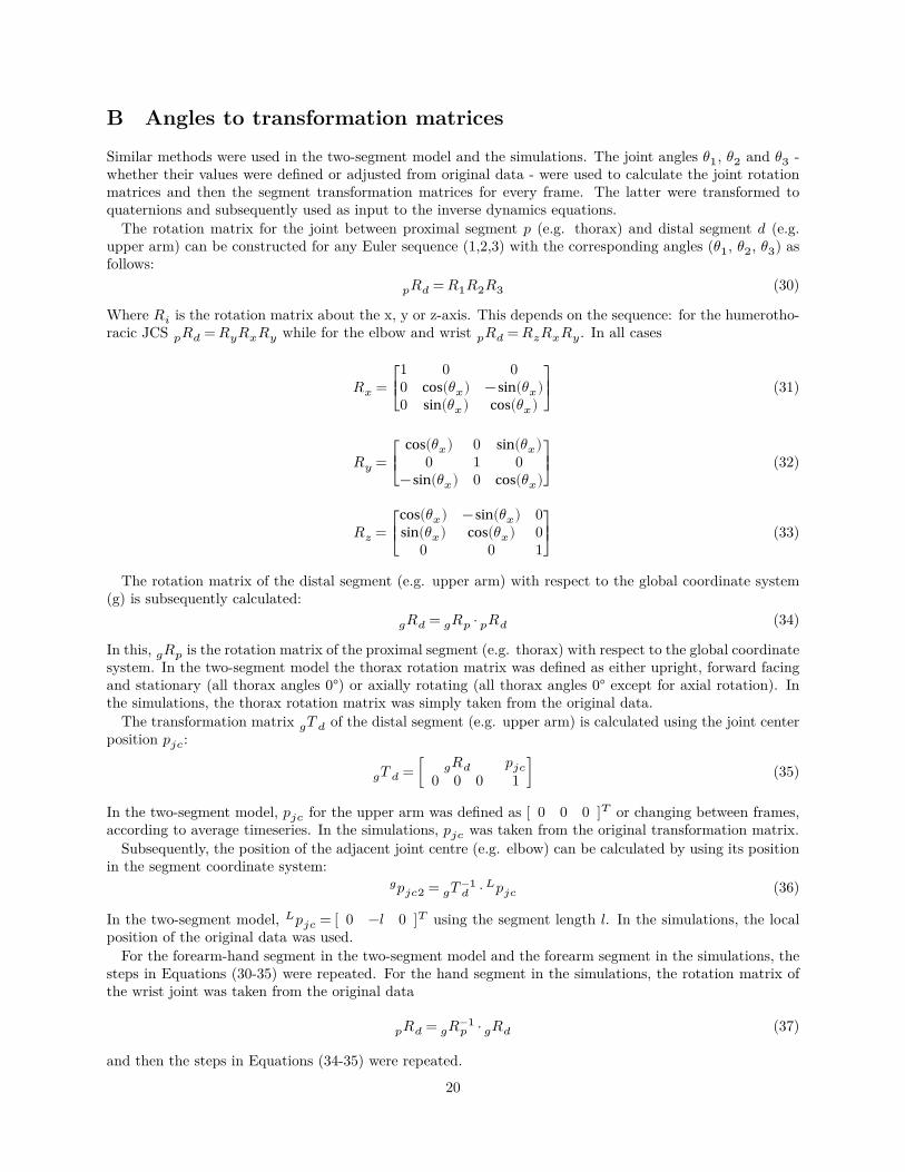
B Angles to transformation matricesSimilar methods were used in the two-segment model and the simulations. The joint angles 𝜃1, 𝜃2 and 𝜃3 -whether their values were defined or adjusted from original data - were used to calculate the joint rotationmatrices and then the segment transformation matrices for every frame. The latter were transformed toquaternions and subsequently used as input to the inverse dynamics equations.
The rotation matrix for the joint between proximal segment 𝑝 (e.g. thorax) and distal segment 𝑑 (e.g.upper arm) can be constructed for any Euler sequence (1,2,3) with the corresponding angles (𝜃1, 𝜃2, 𝜃3) asfollows:
𝑝𝑅𝑑 = 𝑅1𝑅2𝑅3 (30)
Where 𝑅𝑖 is the rotation matrix about the x, y or z-axis. This depends on the sequence: for the humerotho-racic JCS 𝑝𝑅𝑑 = 𝑅𝑦𝑅𝑥𝑅𝑦 while for the elbow and wrist 𝑝𝑅𝑑 = 𝑅𝑧𝑅𝑥𝑅𝑦. In all cases
𝑅𝑥 = ⎡⎢⎣
1 0 00 cos(𝜃𝑥) −sin(𝜃𝑥)0 sin(𝜃𝑥) cos(𝜃𝑥)
⎤⎥⎦
(31)
𝑅𝑦 = ⎡⎢⎣
cos(𝜃𝑥) 0 sin(𝜃𝑥)0 1 0
−sin(𝜃𝑥) 0 cos(𝜃𝑥)⎤⎥⎦
(32)
𝑅𝑧 = ⎡⎢⎣
cos(𝜃𝑥) −sin(𝜃𝑥) 0sin(𝜃𝑥) cos(𝜃𝑥) 0
0 0 1⎤⎥⎦
(33)
The rotation matrix of the distal segment (e.g. upper arm) with respect to the global coordinate system(g) is subsequently calculated:
𝑔𝑅𝑑 = 𝑔𝑅𝑝 ⋅ 𝑝𝑅𝑑 (34)
In this, 𝑔𝑅𝑝 is the rotation matrix of the proximal segment (e.g. thorax) with respect to the global coordinatesystem. In the two-segment model the thorax rotation matrix was defined as either upright, forward facingand stationary (all thorax angles 0°) or axially rotating (all thorax angles 0° except for axial rotation). Inthe simulations, the thorax rotation matrix was simply taken from the original data.
The transformation matrix 𝑔𝑇 𝑑 of the distal segment (e.g. upper arm) is calculated using the joint centerposition 𝑝𝑗𝑐:
𝑔𝑇 𝑑 = [ 𝑔𝑅𝑑 𝑝𝑗𝑐0 0 0 1 ] (35)
In the two-segment model, 𝑝𝑗𝑐 for the upper arm was defined as [ 0 0 0 ]𝑇 or changing between frames,according to average timeseries. In the simulations, 𝑝𝑗𝑐 was taken from the original transformation matrix.
Subsequently, the position of the adjacent joint centre (e.g. elbow) can be calculated by using its positionin the segment coordinate system:
𝑔𝑝𝑗𝑐2 = 𝑔𝑇 −1𝑑 ⋅ 𝐿𝑝𝑗𝑐 (36)
In the two-segment model, 𝐿𝑝𝑗𝑐 = [ 0 −𝑙 0 ]𝑇 using the segment length 𝑙. In the simulations, the localposition of the original data was used.
For the forearm-hand segment in the two-segment model and the forearm segment in the simulations, thesteps in Equations (30-35) were repeated. For the hand segment in the simulations, the rotation matrix ofthe wrist joint was taken from the original data
𝑝𝑅𝑑 = 𝑔𝑅−1𝑝 ⋅ 𝑔𝑅𝑑 (37)
and then the steps in Equations (34-35) were repeated.
20

C Joint kinematicsThis appendix shows the mean ± Standard Deviation (SD) over all pitches for thorax angles with respect tothe global coordinate system, shoulder (gleno-humeral joint) displacement, shoulder (humerothoracic) anglesand elbow joint angles. The input of the two-segment model is based on these values between FC and MER.
Additionally, the mean ± SD of the CoM is plotted below, to be able to compare them to the outcomesof the two-segment model.
Figure 16: Forearm Center of Mass (CoM) mean ± SD forward acceleration in the global frame.
21

Figu
re17
:T
hora
xm
ean
±SD
Eul
eran
gles
over
all2
9pi
tche
s&
shou
lder
mea
n±
SDpo
sitio
nin
the
glob
alco
ordi
nate
syst
emov
eral
l29
pitc
hes,
rela
tive
toth
eW
Upo
sitio
n.
22

Figu
re18
:Sh
ould
eran
del
bow
mea
n±
SDjo
int
Eul
eran
gles
over
all2
9pi
tche
s.
23
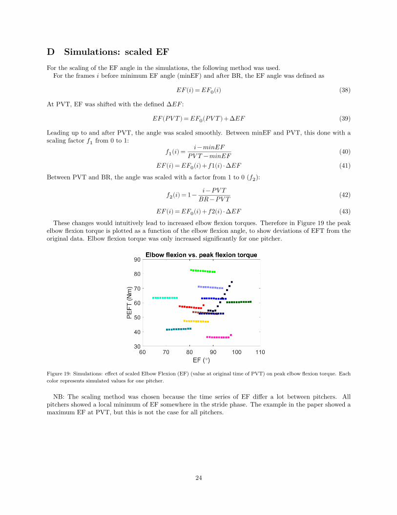
D Simulations: scaled EFFor the scaling of the EF angle in the simulations, the following method was used.
For the frames 𝑖 before minimum EF angle (minEF) and after BR, the EF angle was defined as
𝐸𝐹(𝑖) = 𝐸𝐹0(𝑖) (38)
At PVT, EF was shifted with the defined Δ𝐸𝐹 :
𝐸𝐹(𝑃𝑉 𝑇 ) = 𝐸𝐹0(𝑃𝑉 𝑇 )+Δ𝐸𝐹 (39)
Leading up to and after PVT, the angle was scaled smoothly. Between minEF and PVT, this done with ascaling factor 𝑓1 from 0 to 1:
𝑓1(𝑖) = 𝑖−𝑚𝑖𝑛𝐸𝐹𝑃𝑉 𝑇 −𝑚𝑖𝑛𝐸𝐹 (40)
𝐸𝐹(𝑖) = 𝐸𝐹0(𝑖)+𝑓1(𝑖) ⋅Δ𝐸𝐹 (41)
Between PVT and BR, the angle was scaled with a factor from 1 to 0 (𝑓2):
𝑓2(𝑖) = 1− 𝑖−𝑃𝑉 𝑇𝐵𝑅 −𝑃𝑉 𝑇 (42)
𝐸𝐹(𝑖) = 𝐸𝐹0(𝑖)+𝑓2(𝑖) ⋅Δ𝐸𝐹 (43)
These changes would intuitively lead to increased elbow flexion torques. Therefore in Figure 19 the peakelbow flexion torque is plotted as a function of the elbow flexion angle, to show deviations of EFT from theoriginal data. Elbow flexion torque was only increased significantly for one pitcher.
Figure 19: Simulations: effect of scaled Elbow Flexion (EF) (value at original time of PVT) on peak elbow flexion torque. Eachcolor represents simulated values for one pitcher.
NB: The scaling method was chosen because the time series of EF differ a lot between pitchers. Allpitchers showed a local minimum of EF somewhere in the stride phase. The example in the paper showed amaximum EF at PVT, but this is not the case for all pitchers.
24

E EF and ER within/between subject variation
EF ERSubject Mean Diff Mean Diff
1 90.3 1.0 -130.4 4.82 90.6 3.9 -118.4 7.33 82.7 0.0 -111.3 0.04 83.4 4.5 -134.4 51.05 95.3 11.4 -151.5 23.66 88.0 1.6 -160.6 6.87 86.6 0.1 -147.4 6.88 90.6 4.8 -129.9 31.49 96.6 7.3 -145.2 3.7
10 73.5 4.7 -133.7 10.111 76.1 1.5 -138.2 6.712 90.2 1.9 -132.1 3.5
Mean SD Mean SDAll 87.0 3.3 136.1 15.0
Table 5: Elbow Flexion (EF) and External Rotation (ER) angles at the instant of Peak Valgus Torque (PVT): within andbetween subject variation. Diff = the largest difference found between two pitches of the subject. SD = standard deviation.
F Two-segment model: resultsThis appendix visualizes the effects of the two-segment model inputs on the valgus/varus torque. Themovements, variables and outcomes are plotted for three cases (lowest, reference and highest), as well as theforearm forward acceleration.
From left to right:• The simplified movements: (1) external rotation, (2) horizontal abduction, (3) forward translation and
(4) combination. For (1-3) the input of the movement is plotted. For 4, the input is the combination of(1-3) and plotted is the forearm/hand segment CoM position.
• The variable (constant EF, dynamic EF, ER): in blue the original, in yellow the lowest and in red thehighest variation.
• Valgus torque time series as a result of the movement and variable.• Forearm CoM forward acceleration as a result of the movement and variable.
25
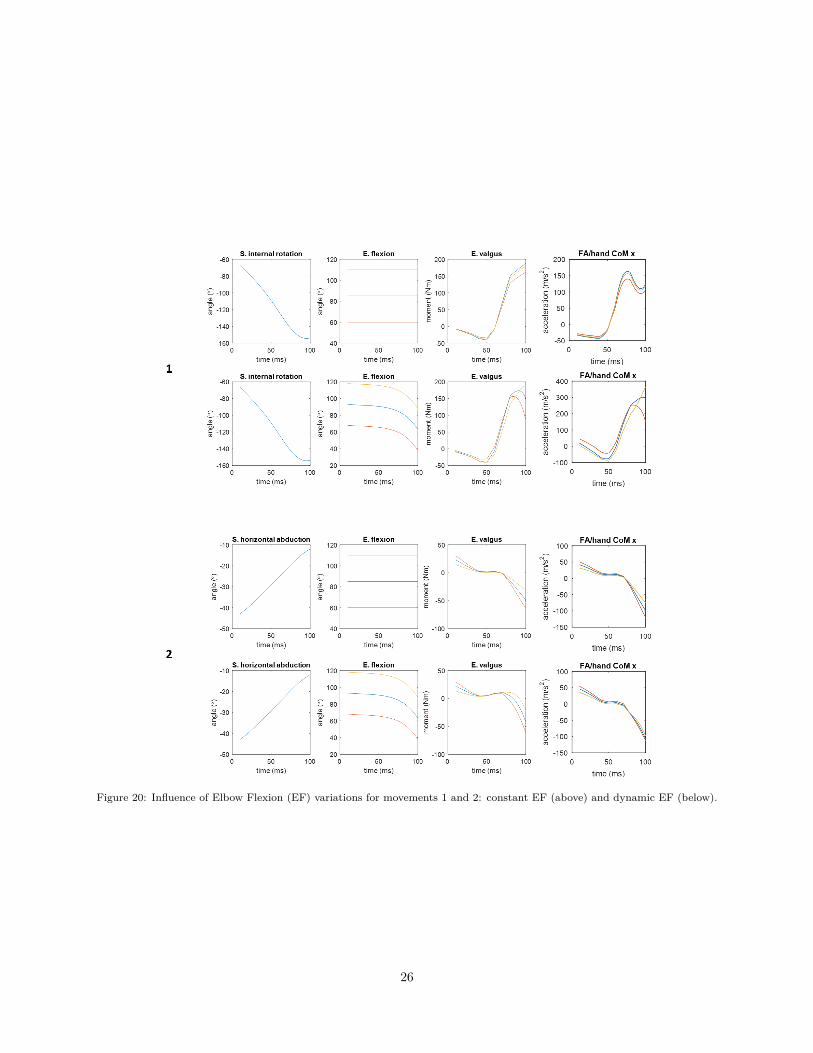
Figure 20: Influence of Elbow Flexion (EF) variations for movements 1 and 2: constant EF (above) and dynamic EF (below).
26
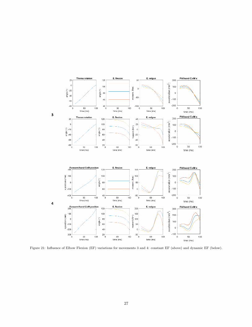
Figure 21: Influence of Elbow Flexion (EF) variations for movements 3 and 4: constant EF (above) and dynamic EF (below).
27

Figure 22: Influence of External Rotation (ER) variations.
28