the influence of combined sheet metal forming on …
TRANSCRIPT
The influence of combined sheet metal forming on the increasing formability by experimental and numerical investigations
XIII International Conference on Computational Plasticity. Fundamentals and ApplicationsCOMPLAS XIII
E. Onate, D.R.J. Owen, D. Peric & M. Chiumenti (Eds)
THE INFLUENCE OF COMBINED SHEET METALFORMING ON THE INCREASING FORMABILITY BY
EXPERIMENTAL AND NUMERICAL INVESTIGATIONS
YALIN KILICLAR∗, O. KORAY DEMIR†, IVAYLO N. VLADIMIROV∗,CHRISTIAN WEDDELING†, STEFANIE REESE∗ AND A. ERMAN
TEKKAYA†
∗ Institute of Applied Mechanics (IFAM)RWTH Aachen University, Germany
e-mail: [email protected], web page: http://www.ifam.rwth-aachen.de
†Institute of Forming Technology and Lightweight Construction (IUL)TU Dortmund, Germany
e-mail: [email protected] - web page: http://www.iul.eu
Key words: Viscoplasticity, Deep Drawing, Material Modelling, Damage, Electromag-netic forming
Abstract. Classical sheet metal forming processes such as deep drawing are widelyused in the industry. The final shape of the deformed sheet metal depends on severalforming factors such as lubrication, punch speed and geometry of the acting tools. Aquantity to measure the formability of the workpiece material is the forming limit diagram(FLD) where maximum major and minor strains are compared to their forming limitcurve (FLC). This work aims to increase these FLCs by combining deep drawing with asubsequent electromagnetic high-speed forming. The principle is based on the fact thatthe maximum formability of the material is reached after the quasi-static deep drawing.At this point, the punch is replaced by one which is modified with coil windings in theedge radius region. A high current pulse is induced through the coils and leads to ahigh-speed electromagnetic post-forming of the sheet. A sharper radius can be observedat the end of the process without material failure which is reflected by a higher FLC. Theprocess chain is investigated for a complex geometry as a cross shaped cup. An efficientviscoplastic material model for large deformations is used for the numerical investigation,coupled with rate dependent Lemaitre [1] type damage formulation. The user materialsubroutine is implemented via the UMAT interface to the commercial explicit package ofLS Dyna.
803
Yalin Kiliclar, O. Koray Demir. Ivaylo N. Vladimirov, Christian Weddeling, Stefanie Reese and A.Erman Tekkaya
1 INTRODUCTION
Due to their characteristics of lightness, corrosion resistance and high mechanical prop-erties, aluminum alloys are finding an increasing use in industrial applications. However,conventional forming methods are still used in this field to deform a sheet into a desiredform. A wide range of phenomena are known influencing the quality of highly differingresults. Related to increasing formability, the use of higher strain rates and non-linearstrain paths are prominent, e.g. in electromagnetic forming ([3]). Therefore, innovativeforming technologies are studied in this paper in order to obtain complex shaped geome-tries. The process chain of forming a cross shaped cup is investigated in cooperationbetween the Institute of Applied Mechanics (IFAM) of the RWTH Aachen and the Insti-tute of Forming Technology and Lightweight Construction (IUL) of the TU Dortmund.For this purpose an experimental setup has been selected which leads to a design combin-ing a standard quasi-static deep drawing forming process with an electromagnetic pulseforming operation.
The simulation and prediction of the complex material behavior demands for an efficientmaterial model. A viscoplastic formulation based on the multiplicative decomposition ofthe deformation gradient in the context of hyperelasticity has been used to model thematerial behavior both during deep drawing and in the electromagnetic forming step. Itincludes all important characteristics as the nonlinear kinematic and isotropic hardening,anisotropy, and ductile damage in the context of continuum damage mechanics, see [4].The model is incorporated into the commercial simulation software LS Dyna.
2 EXPERIMENTAL INVESTIGATION
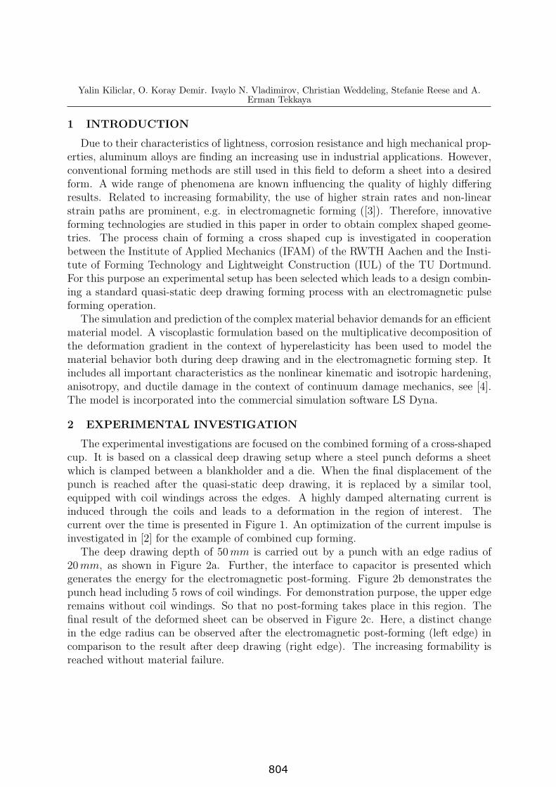
The experimental investigations are focused on the combined forming of a cross-shapedcup. It is based on a classical deep drawing setup where a steel punch deforms a sheetwhich is clamped between a blankholder and a die. When the final displacement of thepunch is reached after the quasi-static deep drawing, it is replaced by a similar tool,equipped with coil windings across the edges. A highly damped alternating current isinduced through the coils and leads to a deformation in the region of interest. Thecurrent over the time is presented in Figure 1. An optimization of the current impulse isinvestigated in [2] for the example of combined cup forming.
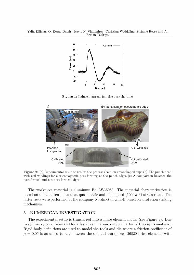
The deep drawing depth of 50mm is carried out by a punch with an edge radius of20mm, as shown in Figure 2a. Further, the interface to capacitor is presented whichgenerates the energy for the electromagnetic post-forming. Figure 2b demonstrates thepunch head including 5 rows of coil windings. For demonstration purpose, the upper edgeremains without coil windings. So that no post-forming takes place in this region. Thefinal result of the deformed sheet can be observed in Figure 2c. Here, a distinct changein the edge radius can be observed after the electromagnetic post-forming (left edge) incomparison to the result after deep drawing (right edge). The increasing formability isreached without material failure.
804
Yalin Kiliclar, O. Koray Demir. Ivaylo N. Vladimirov, Christian Weddeling, Stefanie Reese and A.Erman Tekkaya
Figure 1: Induced current impulse over the time
Figure 2: (a) Experimental setup to realize the process chain on cross-shaped cups (b) The punch headwith coil windings for electromagnetic post-forming at the punch edges (c) A comparison between thepost-formed and not post-formed edges
The workpiece material is aluminum En AW-5083. The material characterization isbased on uniaxial tensile tests at quasi-static and high-speed (1000 s−1) strain rates. Thelatter tests were performed at the company Nordmetall GmbH based on a rotation strikingmechanism.
3 NUMERICAL INVESTIGATION
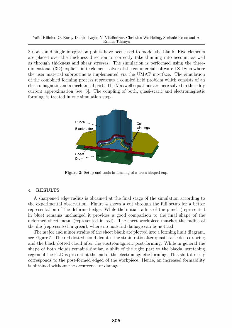
The experimental setup is transferred into a finite element model (see Figure 3). Dueto symmetry conditions and for a faster calculation, only a quarter of the cup is analysed.Rigid body definitions are used to model the tools and die where a friction coefficient ofµ = 0.06 is assumed to act between the die and workpiece. 26820 brick elements with
805
Yalin Kiliclar, O. Koray Demir. Ivaylo N. Vladimirov, Christian Weddeling, Stefanie Reese and A.Erman Tekkaya
8 nodes and single integration points have been used to model the blank. Five elementsare placed over the thickness direction to correctly take thinning into account as wellas through thickness and shear stresses. The simulation is performed using the three-dimensional (3D) explicit finite element solver of the commercial software LS-Dyna wherethe user material subroutine is implemented via the UMAT interface. The simulationof the combined forming process represents a coupled field problem which consists of anelectromagnetic and a mechanical part. The Maxwell equations are here solved in the eddycurrent approximation, see [5]. The coupling of both, quasi-static and electromagneticforming, is treated in one simulation step.
Figure 3: Setup and tools in forming of a cross shaped cup.
4 RESULTS
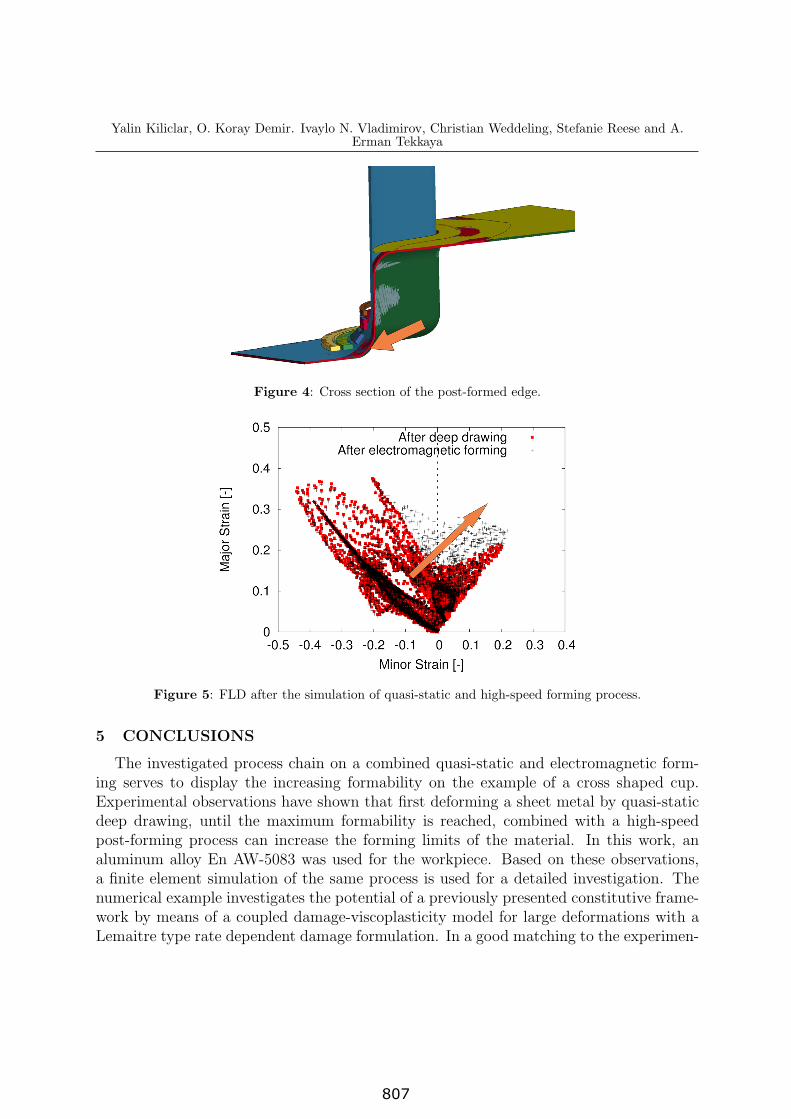
A sharpened edge radius is obtained at the final stage of the simulation according tothe experimental observation. Figure 4 shows a cut through the full setup for a betterrepresentation of the deformed edge. While the initial radius of the punch (representedin blue) remains unchanged it provides a good comparison to the final shape of thedeformed sheet metal (represented in red). The sheet workpiece matches the radius ofthe die (represented in green), where no material damage can be noticed.
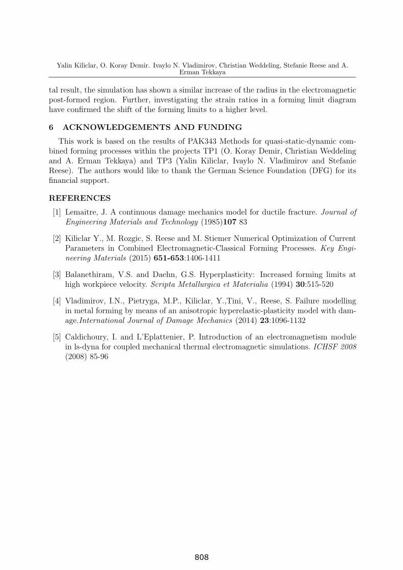
The major and minor strains of the sheet blank are plotted into a forming limit diagram,see Figure 5. The red dotted cloud denotes the strain ratio after quasi-static deep drawingand the black dotted cloud after the electromagnetic post-forming. While in general theshape of both clouds remains similar, a shift of the right part to the biaxial stretchingregion of the FLD is present at the end of the electromagnetic forming. This shift directlycorresponds to the post-formed edged of the workpiece. Hence, an increased formabilityis obtained without the occurrence of damage.
806
Yalin Kiliclar, O. Koray Demir. Ivaylo N. Vladimirov, Christian Weddeling, Stefanie Reese and A.Erman Tekkaya
Figure 4: Cross section of the post-formed edge.
Figure 5: FLD after the simulation of quasi-static and high-speed forming process.
5 CONCLUSIONS
The investigated process chain on a combined quasi-static and electromagnetic form-ing serves to display the increasing formability on the example of a cross shaped cup.Experimental observations have shown that first deforming a sheet metal by quasi-staticdeep drawing, until the maximum formability is reached, combined with a high-speedpost-forming process can increase the forming limits of the material. In this work, analuminum alloy En AW-5083 was used for the workpiece. Based on these observations,a finite element simulation of the same process is used for a detailed investigation. Thenumerical example investigates the potential of a previously presented constitutive frame-work by means of a coupled damage-viscoplasticity model for large deformations with aLemaitre type rate dependent damage formulation. In a good matching to the experimen-
807
Yalin Kiliclar, O. Koray Demir. Ivaylo N. Vladimirov, Christian Weddeling, Stefanie Reese and A.Erman Tekkaya
tal result, the simulation has shown a similar increase of the radius in the electromagneticpost-formed region. Further, investigating the strain ratios in a forming limit diagramhave confirmed the shift of the forming limits to a higher level.
6 ACKNOWLEDGEMENTS AND FUNDING
This work is based on the results of PAK343 Methods for quasi-static-dynamic com-bined forming processes within the projects TP1 (O. Koray Demir, Christian Weddelingand A. Erman Tekkaya) and TP3 (Yalin Kiliclar, Ivaylo N. Vladimirov and StefanieReese). The authors would like to thank the German Science Foundation (DFG) for itsfinancial support.
REFERENCES
[1] Lemaitre, J. A continuous damage mechanics model for ductile fracture. Journal ofEngineering Materials and Technology (1985)107 83
[2] Kiliclar Y., M. Rozgic, S. Reese and M. Stiemer Numerical Optimization of CurrentParameters in Combined Electromagnetic-Classical Forming Processes. Key Engi-neering Materials (2015) 651-653:1406-1411
[3] Balanethiram, V.S. and Daehn, G.S. Hyperplasticity: Increased forming limits athigh workpiece velocity. Scripta Metallurgica et Materialia (1994) 30:515-520
[4] Vladimirov, I.N., Pietryga, M.P., Kiliclar, Y.,Tini, V., Reese, S. Failure modellingin metal forming by means of an anisotropic hyperelastic-plasticity model with dam-age.International Journal of Damage Mechanics (2014) 23:1096-1132
[5] Caldichoury, I. and L’Eplattenier, P. Introduction of an electromagnetism modulein ls-dyna for coupled mechanical thermal electromagnetic simulations. ICHSF 2008(2008) 85-96
808