the influence of biomass burning in the design of an scr ... · the influence of biomass burning in...
TRANSCRIPT
The influence of biomass burning in the design of an SCR installation
by:
Mario Crespi
Technology Manager Flowpac™ WetFGD ALSTOM Power Italia S.p.A.
Environmental Control Systems
Magnus Porle Senior Process Engineer Alstom Power Sweden
Environmental Control Systems
Dr. Ann-Charlotte Larsson Process Engineering Manager
Alstom Power Sweden Environmental Control Systems
Raffaella La Civita Process Engineer
ALSTOM Power Italia S.p.A. Environmental Control Systems
Anders Rooma Nielsen Process Engineer
Environmental Catalyst Division Haldor Topsøe A/S
The influence of biomass burning in the design of an SCR installation Page 2 of 15
Contents: 1. Introduction ........................................................................................................................... 3 2. SCR basics ........................................................................................................................... 3 3. The plant............................................................................................................................. 10 4. Fuel characteristics............................................................................................................. 11 5. Conclusions ........................................................................................................................ 14 6. References ......................................................................................................................... 15
Information contained herein is confidential; it may not be used for any purpose other than for which it has been issued, and may not be used by or disclosed to third parties without written approval of Haldor Topsøe A/S.

The influence of biomass burning in the design of an SCR installation Page 3 of 15
1. Introduction This paper will focus on the challenges of using biomass fuel in the design of a Selective Cata-lytic Reduction (SCR) installation. After a general discussion about the effects of bio-fuels on the catalyst we will discuss the Amager Unit 1 Air Pollution Control (APC) retrofit as an example. While SCR is a well-proven technology, its application with non-conventional fuels like biomass brings specific challenges to the designer. In particular, the main issue is the poisoning of the catalyst by alkali metals and subsequent activity reduction. Several actions can be taken to limit negative effects. For example, plant configuration can help. Also, a tail end installation after Wet FGD (in this case a Flowpac™ turbulent bed absorber) will minimise the amount of poisoning species entering the SCR. Additionally, proper catalyst formulation can be chosen to limit the deactivation.
2. SCR basics NOx reduction by Selective Catalytic Reduction (SCR) is a well-proven air pollution control tech-nology currently employed worldwide. The process is based on the reaction between nitrogen oxides and ammonia in the presence of a catalyst. Below are the main reactions that take place in the process (considering that NO represent approximately 95% of the total amount of nitro-gen oxides):
4 NO + 4 NH3 + O2 = 4 N2 + 6 H2O 2 NO2 + 4 NH3 + O2 = 3 N2 + 6 H2O
Side, unwanted, reactions are the oxidizing of SO2 and of NH3 (anyhow very limited):
2 SO2 + O2 = 2 SO3
4 NH3 + 5 O2 = 4 NO2 + 6 H2O 4 NH3 + 3O2 = 2 N2 + 6 H2O
The reaction mechanism is described in Figure 1
Information contained herein is confidential; it may not be used for any purpose other than for which it has been issued, and may not be used by or disclosed to third parties without written approval of Haldor Topsøe A/S.

The influence of biomass burning in the design of an SCR installation Page 4 of 15
Figure 1: Reaction mechanism
The optimal temperature operating window of the SCR process is between 220°C and 400°C approximately. Catalyst material is basically composed of titanium oxide (TiO2) as support, en-riched with vanadium pentoxide (V2O5) as active components and other species as promoters or suppressors for unwanted side reactions. It can be produced/installed as either monolithic elements or as plate elements arranged in modules (see Figures 2a, 2b and 2c). The aim is to obtain a high superficial area, further increased by the porosity of titanium oxide.
Information contained herein is confidential; it may not be used for any purpose other than for which it has been issued, and may not be used by or disclosed to third parties without written approval of Haldor Topsøe A/S.

The influence of biomass burning in the design of an SCR installation Page 5 of 15
Figure 2a: Extruded Honeycomb Figure 2b: Plate (metal) type catalyst Figure 2c: Corrugated catalyst (composite) type catalyst The catalyst is subject to deactivation as it is exposed to process conditions through:
• Fouling / plugging • Sintering • Abrasion / erosion • Poisoning
Fouling is a macro physical blockage of the pore system by dust or aerosols or formation of surface fouling layers. Plugging of the catalyst channels due to large amount of ash reduces the available active surface. Sintering is a loss of catalyst surface area caused by high tempera-tures (pores will collapse due to a phase transition of the titanium oxide). Abrasion and erosion are mechanical actions caused by fly ash particles impact on the catalyst. These three are of lesser importance for a biomass installation. Poisoning is formally described as the strong chemisorption’s of impurity materials on a catalytic surface which blocks access of reactants to active sites. Catalyst poisons can be categorized as either chemical or physical poisons. Chemical poisons inactivate the active sites whereas physi-cal poisons block the access to the active site and act as fouling agents. Chemical poisons are normally considered as being the strongest poisons. However, physical poisons can cause se-vere deactivation if a dense fouling layer is formed. Based on present knowledge the poisons can be categorized as [8]:
Information contained herein is confidential; it may not be used for any purpose other than for which it has been issued, and may not be used by or disclosed to third parties without written approval of Haldor Topsøe A/S.

The influence of biomass burning in the design of an SCR installation Page 6 of 15
Chemical poisons: As, P Physical poisons: Na, K, Ca and pore condensation of ammonia salts This distinction is not conclusive since some components may act partly as fouling agents and partly as chemical poisons. Poisoning may be a reversible or irreversible process and is generally dependent on concentra-tion of poisoning species and temperature. It is, anyhow, a very complex subject and much re-search has been carried out by Alstom (see references [3], [4], [5], [7] and by Topsøe) on this particular subject. Table 1 below shows the most important poisons for various applications. Na K As P Ca Fe Ni Cr Pb V Coal Bituminous1) (x) x x (x) PRB (x) x x x Bio-fuel Wood x x Straw x x Recycle wood x x x Fuel oil x (x) x x x Fuel oil/diesel (engines) x x x x Syn-gas x x FCC off gas Ethylene cracking furnace x
Sewage sludge x x x x Bone meal x x x x Bone fat x x x x
Coal Co-combustion With
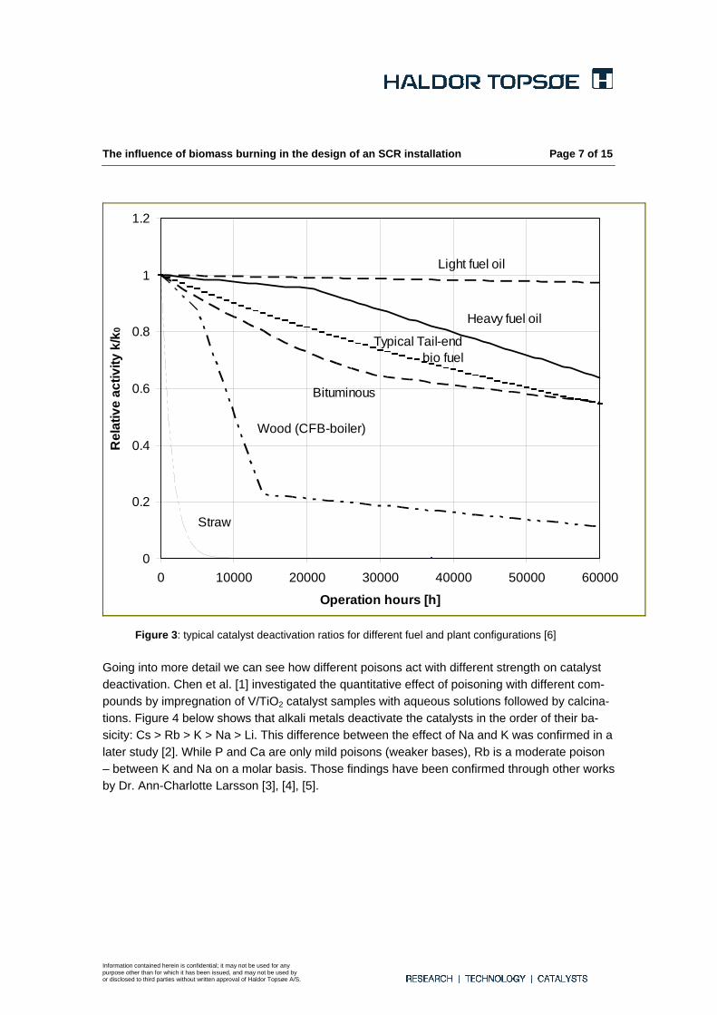
Straw x x x 1) Macro pore plugging is the main contributor (50%) to deactivation along with alkali uptake. Table 1: Important poisons in specific applications [6] For biomass applications, alkali metals are the most serious threat to the catalyst. Different fuels produce different deactivation ratios. Of course it is not only the fuel itself, but it is also the plant configuration and operation that influence this phenomenon. Figure 3 shows typical deactivation ratios for different fuels in different configurations and differ-ent installations (namely high or low dust / tail end installations).
Information contained herein is confidential; it may not be used for any purpose other than for which it has been issued, and may not be used by or disclosed to third parties without written approval of Haldor Topsøe A/S.
The influence of biomass burning in the design of an SCR installation Page 7 of 15
0
0.2
0.4
0.6
0.8
1
1.2
0 10000 20000 30000 40000 50000 60000
Operation hours [h]
Rel
ativ
e ac
tivity
k/k
0
Wood (CFB-boiler)
Bituminous
Heavy fuel oil
Light fuel oil
Straw
Typical Tail-end bio fuel
Figure 3: typical catalyst deactivation ratios for different fuel and plant configurations [6] Going into more detail we can see how different poisons act with different strength on catalyst deactivation. Chen et al. [1] investigated the quantitative effect of poisoning with different com-pounds by impregnation of V/TiO2 catalyst samples with aqueous solutions followed by calcina-tions. Figure 4 below shows that alkali metals deactivate the catalysts in the order of their ba-sicity: Cs > Rb > K > Na > Li. This difference between the effect of Na and K was confirmed in a later study [2]. While P and Ca are only mild poisons (weaker bases), Rb is a moderate poison – between K and Na on a molar basis. Those findings have been confirmed through other works by Dr. Ann-Charlotte Larsson [3], [4], [5].
Information contained herein is confidential; it may not be used for any purpose other than for which it has been issued, and may not be used by or disclosed to third parties without written approval of Haldor Topsøe A/S.

The influence of biomass burning in the design of an SCR installation Page 8 of 15
Information contained herein is confidential; it may not be used for any purpose other than for which it has been issued, and may not be used by or disclosed to third parties without written approval of Haldor Topsøe A/S.
Figure 4: Effect of loading of different poisons on the activity of vanadia-titania cata-lysts. Adapted from [1].
Alkali is believed to act mainly as a combined chemical and physical poison in biomass. Potas-sium, in particular, is present as sub-micron particles mainly as chlorides and sulphates. Sub-micron aerosols adhere to the catalyst surface or diffuse into the macro pores. The aerosols cannot diffuse into the clusters of primary TiO2 support particles, which appear as islands at the catalyst surface. However, the alkalis are very mobile and are readily transported by surface diffusion into the clusters and react with the active sites (see Figure 5 below). The reaction is not reversible: when an active site has reacted with K it is lost for the rest of the lifetime of the catalyst. There are reports that the effect of alkali is stronger at higher temperatures, which could have to do with a temperature dependence of the mobility.
Flue gas Active site Catalyst
Surface
V O V
O OH
V O V
O OK
K2O
Figure 5: Diffusion and poisoning mechanism of alkali
The influence of biomass burning in the design of an SCR installation Page 9 of 15
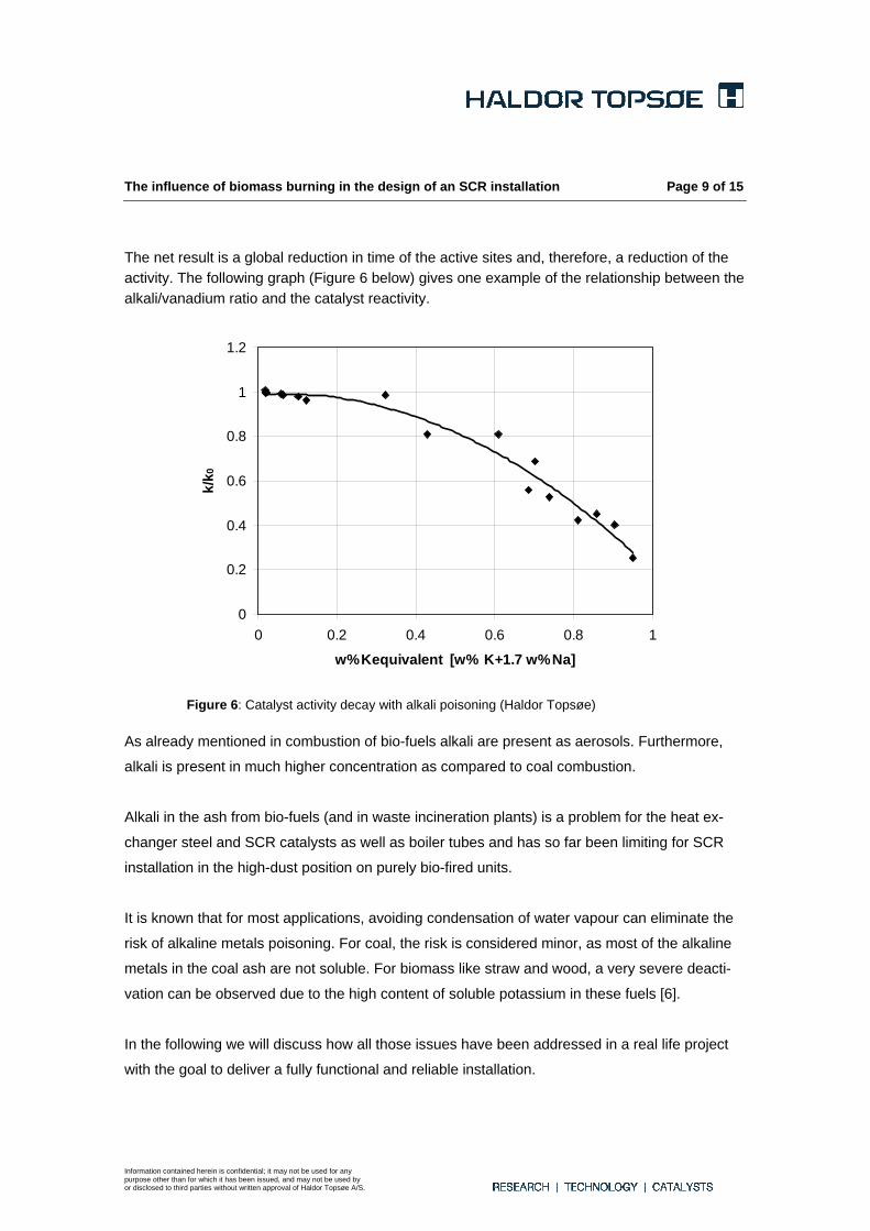
The net result is a global reduction in time of the active sites and, therefore, a reduction of the activity. The following graph (Figure 6 below) gives one example of the relationship between the alkali/vanadium ratio and the catalyst reactivity.
0
0.2
0.4
0.6
0.8
1
1.2
0 0.2 0.4 0.6 0.8 1
w%Kequivalent [w% K+1.7 w%Na]
k/k 0
Figure 6: Catalyst activity decay with alkali poisoning (Haldor Topsøe)
As already mentioned in combustion of bio-fuels alkali are present as aerosols. Furthermore,
alkali is present in much higher concentration as compared to coal combustion.
Alkali in the ash from bio-fuels (and in waste incineration plants) is a problem for the heat ex-
changer steel and SCR catalysts as well as boiler tubes and has so far been limiting for SCR
installation in the high-dust position on purely bio-fired units.
It is known that for most applications, avoiding condensation of water vapour can eliminate the
risk of alkaline metals poisoning. For coal, the risk is considered minor, as most of the alkaline
metals in the coal ash are not soluble. For biomass like straw and wood, a very severe deacti-
vation can be observed due to the high content of soluble potassium in these fuels [6].
In the following we will discuss how all those issues have been addressed in a real life project
with the goal to deliver a fully functional and reliable installation.
Information contained herein is confidential; it may not be used for any purpose other than for which it has been issued, and may not be used by or disclosed to third parties without written approval of Haldor Topsøe A/S.
The influence of biomass burning in the design of an SCR installation Page 10 of 15
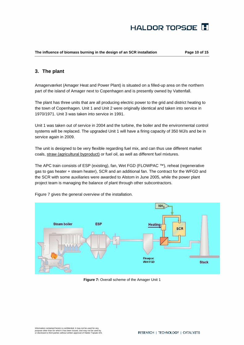
3. The plant Amagerværket (Amager Heat and Power Plant) is situated on a filled-up area on the northern part of the island of Amager next to Copenhagen and is presently owned by Vattenfall. The plant has three units that are all producing electric power to the grid and district heating to the town of Copenhagen. Unit 1 and Unit 2 were originally identical and taken into service in 1970/1971. Unit 3 was taken into service in 1991. Unit 1 was taken out of service in 2004 and the turbine, the boiler and the environmental control systems will be replaced. The upgraded Unit 1 will have a firing capacity of 350 MJ/s and be in service again in 2009. The unit is designed to be very flexible regarding fuel mix, and can thus use different market coals, straw (agricultural byproduct) or fuel oil, as well as different fuel mixtures. The APC train consists of ESP (existing), fan, Wet FGD (FLOWPAC ™), reheat (regenerative gas to gas heater + steam heater), SCR and an additional fan. The contract for the WFGD and the SCR with some auxiliaries were awarded to Alstom in June 2005, while the power plant project team is managing the balance of plant through other subcontractors. Figure 7 gives the general overview of the installation.
Figure 7: Overall scheme of the Amager Unit 1
Information contained herein is confidential; it may not be used for any purpose other than for which it has been issued, and may not be used by or disclosed to third parties without written approval of Haldor Topsøe A/S.
The influence of biomass burning in the design of an SCR installation Page 11 of 15
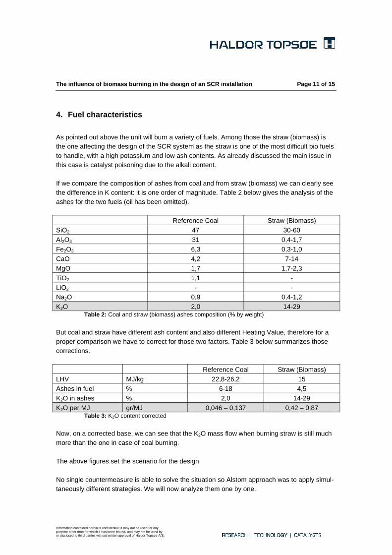
4. Fuel characteristics As pointed out above the unit will burn a variety of fuels. Among those the straw (biomass) is the one affecting the design of the SCR system as the straw is one of the most difficult bio fuels to handle, with a high potassium and low ash contents. As already discussed the main issue in this case is catalyst poisoning due to the alkali content. If we compare the composition of ashes from coal and from straw (biomass) we can clearly see the difference in K content: it is one order of magnitude. Table 2 below gives the analysis of the ashes for the two fuels (oil has been omitted). Reference Coal Straw (Biomass) SiO2 47 30-60 Al2O3 31 0,4-1,7 Fe2O3 6,3 0,3-1,0 CaO 4,2 7-14 MgO 1,7 1,7-2,3 TiO2 1,1 - LiO2 - - Na2O 0,9 0,4-1,2 K2O 2,0 14-29
Table 2: Coal and straw (biomass) ashes composition (% by weight) But coal and straw have different ash content and also different Heating Value, therefore for a proper comparison we have to correct for those two factors. Table 3 below summarizes those corrections. Reference Coal Straw (Biomass) LHV MJ/kg 22,8-26,2 15 Ashes in fuel % 6-18 4,5 K2O in ashes % 2,0 14-29 K2O per MJ gr/MJ 0,046 – 0,137 0,42 – 0,87
Table 3: K2O content corrected Now, on a corrected base, we can see that the K2O mass flow when burning straw is still much more than the one in case of coal burning. The above figures set the scenario for the design. No single countermeasure is able to solve the situation so Alstom approach was to apply simul-taneously different strategies. We will now analyze them one by one.
Information contained herein is confidential; it may not be used for any purpose other than for which it has been issued, and may not be used by or disclosed to third parties without written approval of Haldor Topsøe A/S.

The influence of biomass burning in the design of an SCR installation Page 12 of 15
First approach is to limit as much as possible the amount of poisonous compounds reaching the SCR: Table 4 below gives the mass flow of ashes passing the ESP but the Wet FGD down-stream will collect a certain amount of those ashes. Flue gas flow Nm3/h dry at 6% O2 445900 Dust concentration mg/Nm3 dry at 6% O2 50 Dust mass flow kg/h 22,295
Table 4: Ashes mass flow at ESP outlet at Wet FGD design conditions Dust concentration downstream the ESP is 50 mg/Nm3 (dry @6% O2) whereas dust concentra-tion downstream the Wet FGD is 20 mg/Nm3 (dry @6% O2). Those are both guaranteed figures and results in a removal efficiency of 60%. But, based on test of the Flowpac™ FGD we expect at system outlet a concentration of 10 mg/Nm3 (dry @6% O2), which means a removal efficiency of 80%.
Figure 8: FLOWPACTM absorber
This high ashes collection efficiency (as well as the very high SO2 and SO3 removal efficiency, in excess of 99%) is due to the turbulent bed concept, which is one of the outstanding charac-teristics of this product (see Figure 8 above). Second countermeasure is to minimize the chance that K2O diffuses into the catalyst: since this process is greatly enhanced by the presence of condensed water and since the flue gas leaving the Wet FGD is saturated with water the reheating of the gas is a solution; reheating is accom-plished by a regenerative gas to gas heater plus an additional steam heater (both not part of Alstom supply). Reheating is in any case necessary to bring the flue gas back to the proper temperature window for the NOx reduction to take place. But it is important to ensure that con-densation is not going to happen at any time (whereas for the DeNOx reaction itself it would be enough to have the right T only during operation) because some dust will deposit onto the cata-lyst in time and during start-up, when the catalyst is cold, condensation and thus poisoning may
Information contained herein is confidential; it may not be used for any purpose other than for which it has been issued, and may not be used by or disclosed to third parties without written approval of Haldor Topsøe A/S.

The influence of biomass burning in the design of an SCR installation Page 13 of 15
occur. An additional safety measure is to use compressed air as soot-blowing media instead of steam, again to reduce the risk of water condensation on the catalyst surface. Finally (but not the least important) it is important to select a suitable catalyst composition: Alstom has decided for this project to install catalyst supplied by Haldor Topsøe which has good experience with biomass fuels. The catalyst that will be supplied to the new tail-end SCR DeNOx reactor at Amagerværket Unit 1 is DNX-949 catalyst from Topsøe’s DNX®-series of SCR De-NOx catalysts based on vanadium pentoxide, tungsten trioxide and a titanium dioxide support. Topsøe’s DNX-949 is a special bio-optimized catalyst with high vanadium content and an ensu-ing high number of active sites, making the catalyst less susceptible for poisoning by alkali met-als. Tungsten trioxide is used as the second active ingredient in the catalyst to enhance resistance towards poisoning from alkali metal. The channel pitch of approximately 5 mm allows for opera-tion in a flue gas with a low to medium dust content and the catalyst is thus well suited for a tail-end SCR. Due to the low dust content of the flue gas, a catalyst with a wall thickness of 0.4 mm has been selected. The thin wall gives the catalyst a high void fraction and a high specific sur-face area, yielding a high catalyst activity. The catalyst is front-edge reinforced to allow soot blowing (see Figure 9 below).
Figure 9: DNX® catalyst element detail
All the above-described design features work in synergy to provide the required NOx removal efficiency and catalyst lifetime. They are the result of Alstom know-how and research work in this field as well as the result of Topsøe know-how on the subject.
Information contained herein is confidential; it may not be used for any purpose other than for which it has been issued, and may not be used by or disclosed to third parties without written approval of Haldor Topsøe A/S.

The influence of biomass burning in the design of an SCR installation Page 14 of 15
5. Conclusion We have seen that, although SCR is a well established technology, the use of biomass as fuel poses specific challenges to the SCR designer. In particular the focus is on the poisoning by alkali metals that result in reduced lifetime of the catalyst. Among bio fuels straw is the most difficult to handle because of its high K content. Several counter measures can be taken by the system designer to minimize the risk. Among them we can list:
• Tail end design • High efficiency de-dusting system upstream the SCR (including high performance FGD) • Proper catalyst selection • Proper operating procedures
None of the above counter measures alone is, however, enough to grant a good result. It is therefore the ability and experience of the designer of the SCR installation along with the expertise of the catalyst manufacturer that determines the right mix of those measures for the specific application. We have described them in a specific application case, Amager Power Station, to demonstrate a real life application.
Information contained herein is confidential; it may not be used for any purpose other than for which it has been issued, and may not be used by or disclosed to third parties without written approval of Haldor Topsøe A/S.

The influence of biomass burning in the design of an SCR installation Page 15 of 15
6. References [1]: J.P. Chen, M.A. Buzanowski, R.T.Yang, J.E. Cichanowicz, J. Air Waste Mange. Assoc.
1990, 40, 1403. [2]: H. Kamata, K. Takahashi, C.U.I. Odenbrand, J. Mol. Catal. A. 1999, 139, 189 [3]: A.C. Larsson, J. Einvall, M. Sanati. Deactivation of SCR Catalyst by exposure to aerosol
particles of potassium and zinc salts. Aerosol science and technology. Dec. 2006 [4]: A.C. Larsson, J. Einvall, A. Andersson, M. Sanati. Targeting by comparison with labora-
tory experiments the SCR Catalyst deactivation process by potassium and zinc salts in large scale biomass combustion boiler. Energy & Fuels (2006), 20, 1394-1405.
[5]: A.C. Larsson, J. Einvall, A. Andersson, M. Sanati. Physical and chemical characterization
of potassium deactivation of a SCR for biomass combustion. Proceedings of 12th Nordic Symposium on Catalysis Conference, Thondheim, Norway. May 28-30 2006 (P51, p 198).
[6]: T. Slabiak, Summary of DNX® catalyst tests on bio fuel co-fired boilers, April 2006. [7]: A. Bill, R. Dekker, A. C. Larsson. SCR for biomass derived fuels: operating experience
and performance results from a slip-stream at the Borselle power plant. Paper presented at Power Gen Europe, Milan, 28-30 June 2005.
[8] A. C. Larsson. Study of catalyst deactivation in three different industrial processes. Thesis
for the Degree in Doctor of Technology, Vaxjo University, Sweden, 2007.
Information contained herein is confidential; it may not be used for any purpose other than for which it has been issued, and may not be used by or disclosed to third parties without written approval of Haldor Topsøe A/S.