the inad standard operating procedures (sops) for … generic sops... · 2019-02-24 · recognised...
TRANSCRIPT
GENERIC SOPs CHAPTER 7: MECHANICAL DEMINING
Date:
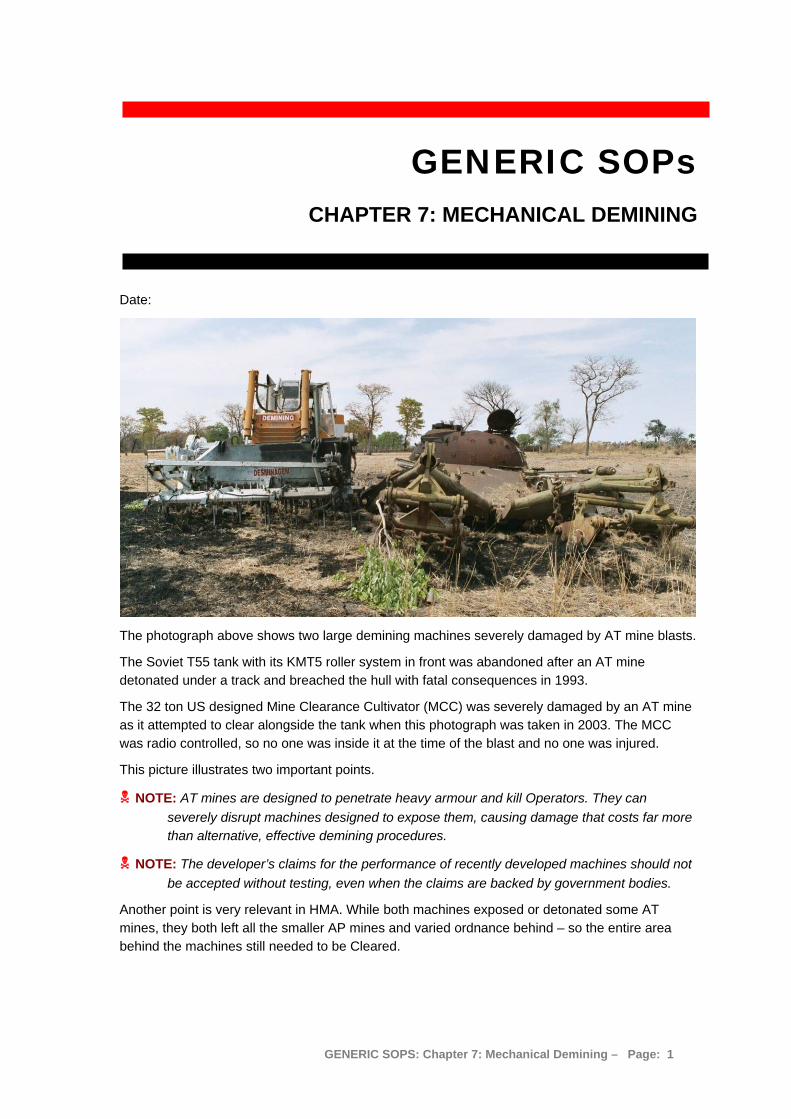
The photograph above shows two large demining machines severely damaged by AT mine blasts.
The Soviet T55 tank with its KMT5 roller system in front was abandoned after an AT mine detonated under a track and breached the hull with fatal consequences in 1993.
The 32 ton US designed Mine Clearance Cultivator (MCC) was severely damaged by an AT mine as it attempted to clear alongside the tank when this photograph was taken in 2003. The MCC was radio controlled, so no one was inside it at the time of the blast and no one was injured.
This picture illustrates two important points.
NOTE: AT mines are designed to penetrate heavy armour and kill Operators. They can severely disrupt machines designed to expose them, causing damage that costs far more than alternative, effective demining procedures.
NOTE: The developer’s claims for the performance of recently developed machines should not be accepted without testing, even when the claims are backed by government bodies.
Another point is very relevant in HMA. While both machines exposed or detonated some AT mines, they both left all the smaller AP mines and varied ordnance behind – so the entire area behind the machines still needed to be Cleared.
GENERIC SOPS: Chapter 7: Mechanical Demining – Page: 1
CHAPTER 7: MECHANICAL DEMINING Contents 1. General ...................................................................................................................................................... 4
1.1 Demining machines in Humanitarian Mine Action.............................................................................. 4 1.2 Principles ........................................................................................................................................... 5 1.3 Speed and safety ............................................................................................................................... 6
1.3.1 Safety when repairing and servicing machines ............................................................................ 7 1.3.2 Safety through armour or remote control...................................................................................... 7
1.4 The real cost of demining machines .................................................................................................. 9 1.5 General rules for mechanical demining.............................................................................................. 9
1.5.1 Designated Inspection Area ....................................................................................................... 10 1.6 Terrain categories ............................................................................................................................ 10 1.7 Machine Deployment Plan ............................................................................................................... 11
1.7.1 Limitations of flailing machines................................................................................................... 11 1.7.2 Limitations of ground tilling and raking machines....................................................................... 12 1.7.3 Limitations of rollers and steel-wheels........................................................................................ 12
1.8 Checking the depth of ground processing........................................................................................ 13 1.8.1 Conducting QA on the depth of ground processing.................................................................... 13
1.9 Using machines for Area Preparation .............................................................................................. 14 1.10 Using machines to locate mined areas ............................................................................................ 14 1.11 Using machines for Area Verification ............................................................................................... 15 1.12 Mechanical Demining Teams........................................................................................................... 16 1.13 Action when a machine detonates a device..................................................................................... 16 1.14 Marking detonations and devices..................................................................................................... 17
1.14.1 Marking detonations with safe-area reference points ................................................................. 17 1.14.2 Marking visible mines or devices................................................................................................ 18
1.15 Actions when a mine or ERW is exposed ........................................................................................ 18 1.16 CASEVAC procedures during machine use..................................................................................... 18
1.16.1 Initial accident investigation........................................................................................................ 21 1.17 Encountering wire obstructions ........................................................................................................ 21 1.18 When a machine catches fire inside the SHA .................................................................................. 22 1.19 Recovering a broken-down or damaged machine............................................................................ 23
1.19.1 Using a Recovery vehicle........................................................................................................... 23 1.19.2 Making safe access around the machine ................................................................................... 23
2. Management of mechanical demining operations .................................................................................... 24 2.1 Deployment limitations..................................................................................................................... 24 2.2 Mechanical tasking orders ............................................................................................................... 24 2.3 Mechanical Demining - site requirements ........................................................................................ 25 2.4 Mechanical safety-distances ............................................................................................................ 25 2.5 General safety measures................................................................................................................. 26 2.6 Mechanical Reporting requirements ................................................................................................ 26
2.6.1 Machine documentation ............................................................................................................. 26 3. Using converted excavators ..................................................................................................................... 27
3.1 Excavator tool attachments.............................................................................................................. 28 3.2 Constraints on use ........................................................................................................................... 29
3.2.1 General operating rules.............................................................................................................. 29 3.2.2 Performance in different terrain .................................................................................................. 29
3.3 Deploying the flail or rotary cutter .................................................................................................... 29 3.3.1 Cutting breaches ........................................................................................................................ 30 3.3.2 Cutting adjacent breaches.......................................................................................................... 32 3.3.3 Cutting spaced breaches............................................................................................................ 32 3.3.4 Processing road verges mechanically ........................................................................................ 33 3.3.5 Using the excavation bucket in a SHA ....................................................................................... 33 3.3.6 Clearing the soil in the Inspection areas..................................................................................... 34 3.3.7 Ground preparation and vegetation cutting ................................................................................ 35 3.3.8 Moving obstacles with the rake or bucket................................................................................... 35 3.3.9 Using the Sifting bucket.............................................................................................................. 35 3.3.10 Using the Arjun rake................................................................................................................... 36
4. The MV-4 demining flail............................................................................................................................ 37 4.1 Constraints on using the MV-4......................................................................................................... 37
4.1.1 Terrain constraints for MV-4 deployment ................................................................................... 38 4.1.2 Performance in different terrain .................................................................................................. 39 4.1.3 Safety constraints....................................................................................................................... 39 4.1.4 Observation posts ...................................................................................................................... 39
GENERIC SOPS: Chapter 7: Mechanical Demining – Page: 2
4.2 Patterns of MV-4 deployment........................................................................................................... 40 4.2.1 Overlap to ensure ground coverage ........................................................................................... 40 4.2.2 Straight line cuts......................................................................................................................... 40 4.2.3 Side-to-Side passes ................................................................................................................... 40 4.2.4 Turning the MV-4 inside the SHA............................................................................................... 41 4.2.5 The Snail system........................................................................................................................ 42 4.2.6 Covering the same area several times ....................................................................................... 43
4.3 Deploying the MV-4 ......................................................................................................................... 43 4.3.1 Preparing safe-areas.................................................................................................................. 43 4.3.2 Processing breaches.................................................................................................................. 44 4.3.3 Using the MV-4 to process road verges ..................................................................................... 45 4.3.4 Using the MV-4 for cutting vegetation ........................................................................................ 45
5. CASSPIR with steel-wheels (and rollers) ................................................................................................. 46 5.1 Constraints on using the steel-wheels and rollers............................................................................ 47
5.1.1 Terrain constrains....................................................................................................................... 47 5.2 CASSPIR deployment patterns........................................................................................................ 47
5.2.1 Side-to-side procedure ............................................................................................................... 48 5.2.2 The Snail procedure ................................................................................................................... 49
5.3 Deploying the CASSPIR with steel-wheels (and rollers) .................................................................. 50 5.3.1 Preparing safe-areas.................................................................................................................. 51 5.3.2 Preparing wide areas ................................................................................................................. 51 5.3.3 Preparing breaches .................................................................................................................... 51 5.3.4 Preparing roads.......................................................................................................................... 53
6. MineWolf .................................................................................................................................................. 54 6.1 Constraints on using the MineWolf .................................................................................................. 54
6.1.1 Terrain constraints for MineWolf deployment ............................................................................. 55 6.1.2 Performance in different terrain .................................................................................................. 56 6.1.3 Safety constraints....................................................................................................................... 56
6.2 MineWolf deployment patterns......................................................................................................... 57 6.2.1 Side-step deployment................................................................................................................. 57 6.2.2 Turning inside the SHA .............................................................................................................. 58 6.2.3 The Snail-system........................................................................................................................ 59 6.2.4 The “U-Turn System”.................................................................................................................. 60
6.3 MineWolf processing roads.............................................................................................................. 61 6.4 MineWolf processing verges ............................................................................................................ 61
7. Mine Protected Vehicles (MPV)................................................................................................................ 62 8. MPV with VMMD array ............................................................................................................................ 63
8.1 The VMMD Team............................................................................................................................. 64 8.2 VMMD deployment .......................................................................................................................... 64 8.3 Road search with the VMMD ........................................................................................................... 66
8.3.1 Investigating a VMMD indication on a road ................................................................................ 66 8.4 Task consolidation ........................................................................................................................... 67
9. MPV with REST system ........................................................................................................................... 68 9.1 REST using MEDDS sampling......................................................................................................... 68
9.1.1 Constraints on using an MPV with MEDDS sampling ................................................................ 68 9.2 The vehicle mounted sampling Team .............................................................................................. 69 9.3 Sampling Procedure ........................................................................................................................ 69
9.3.1 Task site layout and sampling procedure ................................................................................... 69 9.4 Management of MEDDS filter tubes................................................................................................. 70
9.4.1 Prevention of Contamination ...................................................................................................... 71 9.5 Traffic regulation during sampling .................................................................................................... 71 9.6 Internal MEDDS QA and QC............................................................................................................ 72
9.6.1 The Tubes .................................................................................................................................. 72 9.6.2 GPS............................................................................................................................................ 72
GENERIC SOPS: Chapter 7: Mechanical Demining – Page: 3

1. General Demining machines are not mine Clearance machines. This is because “clearance” is defined in the IMAS as the removal of all mines and ERW to a specified depth. No currently available demining machine is able to remove all the mines and ERW that may be a Task. They cannot reliably detonate all pressure-operated devices and stand little chance of detonating devices with pins that must be pulled, or of disrupting common ERW other than mines. On uneven ground, all demining machines can fail to process the ground to a constant depth, and so may miss mines or ERW altogether. They can also leave mines and ERW damaged and in a more sensitive condition than they were before the machine was used.
The performance claims made for many machines are misleading and the manufacturer’s recommendations for use are often inappropriate. The use of all machines must be based on unbiased field data. Objective trials should always be conducted to determine the limitations of a new machine.
As long as the machine is not expected to conduct Clearance without manual or MDD follow-up, a wide range of machines can be used in any way that does not increase risk to staff. Proposed machines must be considered with reference to the hazards expected where they will be used, any dangers inherent in their use, and the real cost of their deployment.
The apparent cost-effectiveness of many machines is often shown to be illusory when it is recognised that the land will still need to be Cleared after the machine has been used. The use of machines that make a tolerably safe passage for soldiers by applying pressure over most of the ground and detonating or disrupting most of the mines does not constitute Clearance in Humanitarian Demining. Also, mechanically disrupting mine patterns can be a disadvantage because (by spreading it) it can increase the area that must be properly Cleared after the machine has passed.
Despite their limitations, demining machines can increase the speed with which land is released very dramatically as long as their use is sensibly integrated with the use of other available tools and procedures.
1.1 Demining machines in Humanitarian Mine Action Machines are used in Humanitarian Mine Action for two main reasons. The first is to enhance the safety of demining staff, and the second is to increase the speed with which deminers can release land.
This SOP covers a range of machines. It must be extended when any machine not covered is to be used inside a Task area (SHA/CHA).
To apply each machine appropriately, all staff involved in Task planning must know each machine’s optimal operating conditions, availability and deployment constraints. This will allow the Task planners to select the appropriate machine or combinations of machines and tools to ensure the most effective outcome.
The machines covered in this Chapter are:
1. Converted excavator and tools; 2. MV-4 Mini-flail; 3. CASSPIR with steel-wheels/rollers; 4. MineWolf with flail and tiller; 5. Mine Protected Vehicles (MPVs); 6. MPV with detector array; and 7. MPV with REST system.
GENERIC SOPS: Chapter 7: Mechanical Demining – Page: 4
Mechanical demining is the use of machines inside a SHA/CHA during demining operations. It may involve a single machine employing one tool, a single machine using a variety of tools or a number of machines employing a variety of tools.
Demining machines can be divided into four general categories. Some can be used in more than one role:
1. Ground processing machines – machines whose stated purpose is to dig to a set depth and destroy mines using a rotating tiller tool, flail, rake or excavator. These machines do not Clear ground of all mines and ERW.
2. Ground preparation machines – machines that are primarily designed to improve the efficiency of demining operations by reducing or removing vegetation or preparing the ground. These machines may detonate some mines but do not Clear ground of all mines and ERW.
3. Mine and ERW detection machines – these are Mine Protected Vehicles with either a large metal-detector array mounted on the front or the back, or a vapour detection system on board. These machines are only detectors. The signals identified by the detection system must be investigated using manual demining and/or MDD procedures.
4. Mine Protected Vehicles (MPV) – vehicles specifically designed to protect the occupants and equipment from the effects of a mine detonation. When fitted with suitable wheels, these may be used to crush vegetation and attempt to find mined areas by detonating mines under the steel wheels.
Demining machines can be used to:
1. Locate mined areas by detonating one or more mines in an area; 2. Remove vegetation before manual and MDD search; 3. Prepare ground for manual and MDD follow up; 4. Excavate ground and move it to be searched in another place; 5. Locate areas in which there is a high probability of mines and ERW; and 6. Raise confidence for the end-users of land with No Known Threat.
Generally, when a mine has been detonated, the machine should not be used to deliberately detonate others in the mine pattern. This is because the machine will disrupt the pattern and may scatter or bury mines and ERW in a way that adds to deminer risk and increases the time spent in manual demining or MDD follow-up. The machine may be used to approach the suspected mined area in other places to try to confirm the direction and extent of the mined area. When the machine has helped to identify the mined area, the mined area must be Cleared using manual demining or MDD procedures. The area Cleared should extend on all sides of any evidence of mines that is found. The area of the extension should always give complete confidence that any other mines will be found. In areas with patterned minefields, that area may be as little as five metres in all directions. In areas with randomly placed mines, it may be necessary to Clear the entire SHA/CHA to gain confidence that no mines have been missed.
1.2 Principles Because, at any Task, all machines may leave mines and ERW damaged and in a more sensitive condition than they were before the machine was used, the following principles for the use of demining machines apply:
1. Ground processed by all machines will not be recorded as Cleared without appropriate follow up by manual demining or MDD procedures. The machine prepares the ground. The manual and/or MDD assets Clear the ground.
GENERIC SOPS: Chapter 7: Mechanical Demining – Page: 5
2. Ground processed by a machine and then by manual demining or MDD procedures will then be recorded as Reduced or Cleared depending which procedures are used. Rules covering Reduction and Clearance are given in Chapter 3 in these SOPs.
3. When land is ready for release but the end-user lacks confidence in the land, the land may be processed by a machine in order to build end-user confidence. This process is called Verification and may be conducted without the safety constraints of other operations inside a SHA/CHA and without any follow-up procedures being used. Rules covering Verification are listed in Chapter 3 of these SOPs.
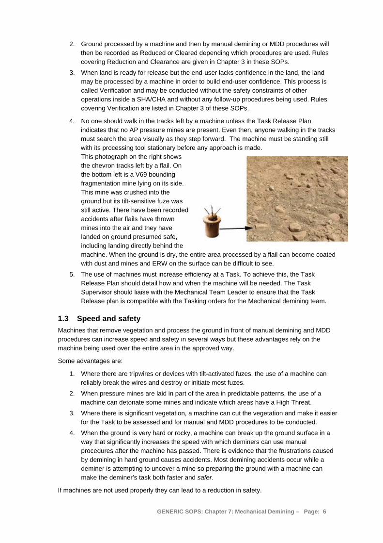
4. No one should walk in the tracks left by a machine unless the Task Release Plan indicates that no AP pressure mines are present. Even then, anyone walking in the tracks must search the area visually as they step forward. The machine must be standing still with its processing tool stationary before any approach is made. This photograph on the right shows the chevron tracks left by a flail. On the bottom left is a V69 bounding fragmentation mine lying on its side. This mine was crushed into the ground but its tilt-sensitive fuze was still active. There have been recorded accidents after flails have thrown mines into the air and they have landed on ground presumed safe, including landing directly behind the machine. When the ground is dry, the entire area processed by a flail can become coated with dust and mines and ERW on the surface can be difficult to see.
5. The use of machines must increase efficiency at a Task. To achieve this, the Task Release Plan should detail how and when the machine will be needed. The Task Supervisor should liaise with the Mechanical Team Leader to ensure that the Task Release plan is compatible with the Tasking orders for the Mechanical demining team.
1.3 Speed and safety Machines that remove vegetation and process the ground in front of manual demining and MDD procedures can increase speed and safety in several ways but these advantages rely on the machine being used over the entire area in the approved way.
Some advantages are:
1. Where there are tripwires or devices with tilt-activated fuzes, the use of a machine can reliably break the wires and destroy or initiate most fuzes.
2. When pressure mines are laid in part of the area in predictable patterns, the use of a machine can detonate some mines and indicate which areas have a High Threat.
3. Where there is significant vegetation, a machine can cut the vegetation and make it easier for the Task to be assessed and for manual and MDD procedures to be conducted.
4. When the ground is very hard or rocky, a machine can break up the ground surface in a way that significantly increases the speed with which deminers can use manual procedures after the machine has passed. There is evidence that the frustrations caused by demining in hard ground causes accidents. Most demining accidents occur while a deminer is attempting to uncover a mine so preparing the ground with a machine can make the deminer’s task both faster and safer.
If machines are not used properly they can lead to a reduction in safety.
GENERIC SOPS: Chapter 7: Mechanical Demining – Page: 6
1. If mechanically processed ground is declared Clear without manual demining or MDD follow-up, the safety of the end-users of the land will be reduced. This must never be allowed.
2. Deminers following a machine must be trained in how to approach the kind of damaged and disrupted devices that may be left behind.
3. Deminers will rely on the machine to have processed all of the ground as intended. Machine Operators must ensure that the entire ground is processed and no areas are missed or processed to less than the required depth.
1.3.1 Safety when repairing and servicing machines
Mechanics should only work on machines for which they have had training and only conduct procedures in accordance with the manufacturer’s instructions.
The training of mechanics must stress the following general safety concerns when operating any machinery. These concerns are entirely based on experience:
1. Mechanics must not work on machines with high-pressure hydraulic systems while the engine is running;
2. The battery must be disconnected before working on any electrical system;
3. The alternator must always be disconnected before any electric arc-welding is conducted;
4. When machines or parts of machines are held suspended in the air, no one should work or stand beneath the suspended part(s) until they have been appropriately supported; and
5. Persons must not use their fingers to align holes in heavy parts.
Mechanics should have the relevant manufacturers’ handbooks available at all times.
1.3.2 Safety through armour or remote control
Machines may be operated by a person inside the machine or may be remotely controlled by an Operator(s) at a distance from the machine. A few manufacturers offer machines that can be controlled either way but this combines the expense of heavy armouring to protect an Operator and the high cost of a remote control system so should generally be avoided.
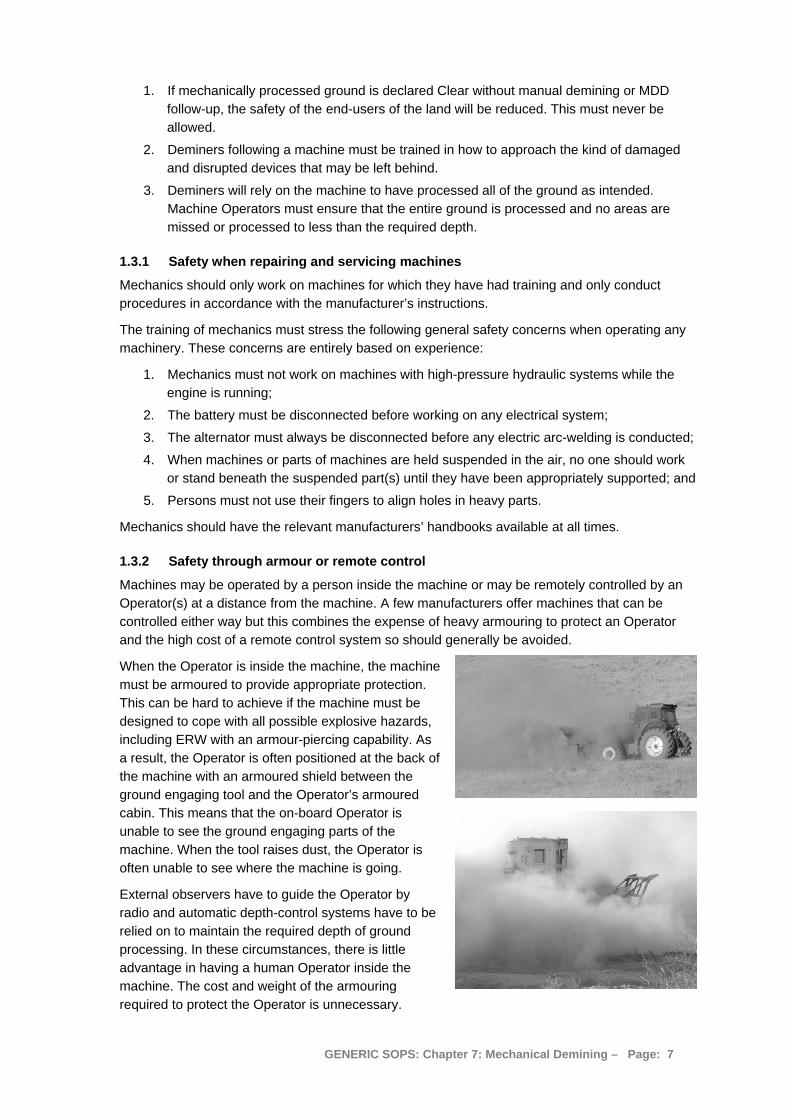
When the Operator is inside the machine, the machine must be armoured to provide appropriate protection. This can be hard to achieve if the machine must be designed to cope with all possible explosive hazards, including ERW with an armour-piercing capability. As a result, the Operator is often positioned at the back of the machine with an armoured shield between the ground engaging tool and the Operator’s armoured cabin. This means that the on-board Operator is unable to see the ground engaging parts of the machine. When the tool raises dust, the Operator is often unable to see where the machine is going.
External observers have to guide the Operator by radio and automatic depth-control systems have to be relied on to maintain the required depth of ground processing. In these circumstances, there is little advantage in having a human Operator inside the machine. The cost and weight of the armouring required to protect the Operator is unnecessary.
GENERIC SOPS: Chapter 7: Mechanical Demining – Page: 7

Efficient remote-control systems are also expensive, but remotely controlled machines can be attractive because their armouring can be limited, allowing their size, weight and overall cost to be greatly reduced. Smaller machines can have shorter ground-engaging tools that can follow undulating ground contours and negotiate obstacles more efficiently. This means that, appropriately operated, they can maintain a more constant quality of ground processing. Their reduced size and weight can also mean that they can be transported to the working areas more easily, and use far less fuel than their larger cousins.
Remotely controlled machines that attempt to retain enough armouring to be able to detonate AT mines (like the Bozena-5 shown below or the Tempest) should be avoided.
It is claimed that these machines can withstand an AT detonation under the flail with “repairable damage”. What is “repairable” is a matter of opinion. Also, while they may detonate AT mines with their flails, they may also detonate AT mines that the flail has missed under their tracks, which will result in catastrophic damage that is unlikely to be economical to repair.
Because AT mines are designed to immobilise battle-tanks it is be no surprise that the result of an AT blast on the largest machines is often catastrophic damage, as shown in the photograph of a Hydrema flail shown on the right.
When the machine is relatively small, it will not only sustain extensive blast damage above the position of the mine. It will also be thrown into the air and can be crushed by its own weight on landing.
NOTE: Small machines must not be used in areas where active AT mines or movement sensitive ERW with armour-piercing capabilities are anticipated.
The preferred mini-flail is the Dok-Ing MV-4 which has been proven in many theatres and which is not designed to withstand an AT mine blast.
The preferred small tilling machine is the Mini-MineWolf. However, the power and weight required to till rocky ground to a reliable depth means that the Mini-MineWolf is not really small or light and the cost is high.
The preferred vegetation cutting machine must be remotely controlled and have lightweight protection against blast. It should be small enough to be easily transportable without a specialised vehicle. A mini-flail may be used in this mode. Also, a converted “Spider” or the dedicated “Grasshopper” are current options. The Grasshopper is shown below left, and the Spider on the right. Both can be especially useful for cutting vegetation in advance of MDD procedures, butboth may be damaged by AP mine blasts.
GENERIC SOPS: Chapter 7: Mechanical Demining – Page: 8
1.4 The real cost of demining machines The purchase cost of a machine is only one part of the total cost of ownership.
Other main costs are:
1. Transporting the machine to the SHA;
2. Fuel consumption per hour of use;
3. Service consumables including hydraulic oil and filters;
4. Tools and specialist maintenance equipment;
5. Replacement parts, including ground engaging chains, hammers and chisels; and
6. Specialist staff to operate and maintain the machine.
The average cost per hour of use of a large machine must be determined before a machine is purchased. No machine should be bought unless it is certain to be used over a long enough period to justify the cost of purchase and Operator training.
When large, purpose-designed demining machines are wanted, hiring the machine complete with Operators, spare-parts, consumables and support staff may be the most economic way to meet the need.
When considering using converted plant machinery, local purchase and alteration is usually the most economic and sustainable way to acquire the asset.
Whenever considering acquiring any remotely controlled equipment, purchase or hire from specialists should be preferred unless a proven radio-control expertise is available locally.
1.5 General rules for mechanical demining The following are rules that must be applied when using any machine in a SHA.
1. Machines can only be deployed in the SHA/CHA at Tasks where there is a demining Platoon with at least one Section of Deminers and a Task Supervisor with overall responsibility for the management of the Task Release Plan. The Task Supervisor controls the Mechanical Team and may suspend the work of a machine at any time.
2. No machine can be operated in a SHA/CHA until the Mechanical Team Leader has confirmed that all unauthorised people are at the required safety distance.
3. No machine can be operated inside the SHA/CHA unless the Mechanical Team Leader is on site and in control of the mechanical operation.
4. No machine can be operated inside a SHA/CHA unless a Paramedic and ambulance are available at the Task site. The Paramedic should be no more than five minutes away from the machine.
5. When the Operator is assisted by Observers, the Operator must be aware of the Observers’ positions and have communication with them.
6. The machine Operator and any Observers must always have a means of communication with the Mechanical Team Leader.
7. All Operators and Observers must wear PPE unless suitably protected inside an MPV or behind an armoured shield. When inside an MPV or behind an armoured shield, they must have PPE with them for use in an emergency.
8. When any ground processing machine is operated close to a road or an area where people may be present, the machine should be directed so that it faces away from those areas when it starts to process the ground and an effective means of redirecting members of the public should be in place.
GENERIC SOPS: Chapter 7: Mechanical Demining – Page: 9
9. When any ground processing machine is first used in a region, its ability to detonate or disrupt the anticipated devices should be tested in controlled trials. This will allow its effectiveness in similar conditions to be predicted. Those trials must involve the use of real devices in the same condition and the same environment as those expected. It is often appropriate to conduct the trial in a known mined area, and then follow the machine with full manual demining or MDD Clearance procedures to determine the result.
10. When leaving the SHA/CHA after using tools to process the ground, the machine must move directly to the designated Inspection Area to be checked as described in Part 1.5.1 of this Chapter.
1.5.1 Designated Inspection Area
At any Task site where machines will be used to process ground inside the SHA/CHA, there must be at least one designated Inspection Area close to the base-line that is large enough to allow free movement around any of the machines that may be used at that part of the Task.
When a machine leaves the SHA/CHA after processing the ground it must always be moved directly to the Inspection Area.
At the Inspection Area, a deminer in PPE must inspect the machine and its tool for any hazardous devices or parts of devices that may be on or attached to machine parts. When vision is obstructed by roots, earth or vegetation, the deminer may use a long-handled heavy rake to cautiously remove the obstructions.
If any suspicious devices or parts of devices are discovered, the deminer must inform the Mechanical Team Leader who must inform the Platoon Commander or Platoon Supervisor, requesting the presence of an EOD Operative to deal with the device.
All other staff must withdraw to the appropriate working-distance while the EOD Operative takes appropriate action. If the EOD Operative decides to use a pulling procedure to remove the device from the machine, all staff must withdraw to the safety-distance appropriate for the device.
When there is no hazard, the machine Operator and Mechanic can clean and carry out repairs or field maintenance tasks on the machine. Fuelling and general maintenance should not be conducted close to the SHA/CHA, so the machine should be withdrawn. Any maintenance tasks that involve the changing of fluids should be carried out in another area where waste fluids can be captured and disposed of appropriately.
1.6 Terrain categories Machine manufacturers sometimes specify the terrain over which their machine is designed to work, and the machine’s possible performance in those conditions. The defining features of the categories are varied and often inconsistent. Before experience is gained, the machine’s anticipated performance should be calculated based on 50% of the manufacturer’s claim. The calculation must also take account of the fact that the machine may need to work over the same ground several times in order to achieve the required depth of processing.
For the purposes of internal assessment, obstacles are trees, wire, fences, trenches, ditches, ponds, buildings, vehicle wrecks or large rubbish piles. The following terrain categories should be used:
Category A terrain is either flat or with gentle slopes with dry topsoil. It has no rocks and stones. The vegetation has a maximum stem thickness of 3cm. There is no more than one obstacle in each 200 square metres. If these conditions are not met, the terrain should be classed as Category B, C or D. All demining machines can be used in category A terrain.
GENERIC SOPS: Chapter 7: Mechanical Demining – Page: 10
Category B terrain is either flat or has moderate slopes up to 15º. The vegetation has a maximum stem thickness of 10cm. There should be few rocks and stones. There can be obstructions in the working area but the gaps between them must be at least ten metres so that the machines can manoeuvre between them. If any of these conditions are not met, the terrain should be classed as Category C or D. When selecting demining machines, only machines that can work in Category B terrain should be considered.
Category C terrain can be very uneven with slopes up to 20º. The ground can be wet and soft or rocky. The vegetation can be dense with bushes higher than 1.5 metres over up to 60% of area. There can be obstructions such as wire, fences, vehicle wrecks or large rubbish piles that may be close together. Heavy machines may become easily bogged-down in wet ground and may be unable to process the ground effectively while climbing slopes. In rocky ground, the wear on ground processing tools can make it uneconomic to try to maintain a processing depth.
Category D terrain can have slopes of more than 20º. The ground may have exposed bedrock or a rock covered surface. There may be dense trees, ditches, trenches and other obstructions. Progress in Category D terrain is usually very slow and expensive for any machine and most can only work in parts of the area.
1.7 Machine Deployment Plan Before a machine is used, the Task Supervisor will issue a Tasking order to the Mechanical Team Leader. The Tasking order should have been prepared in discussion with the Mechanical team Leader. It will include a map showing details of where the machine should be used and, when the machine digs into the ground, the depth of ground penetration required. On receipt of a Tasking order, the Mechanical team Leader must make a Machine Deployment plan designed to achieve the required results. The Mechanical Team Leader should plan the ground-pattern over which to run the machine in order to ensure that the machine covers the entire area and can be easily seen while it works. The range of mechanical deployment patterns that can be worked depends partly on the machine being used. Approved deployment patterns are described in Part 2 of this Chapter.
The Mechanical Team Leader must make a plan that is practical and will not result in injury or in unnecessary damage to the machine and its tools.
The Task Supervisor must ensure that the Machine deployment plan meets the requirements of the Tasking order. When machines cannot be used in the way that the Task Supervisor wants, the Mechanical Team Leader should have the authority to restrict their use.
The Tasking order and the Machine Deployment Plan become a part of the Task Release Plan and copies should be kept in the Task Folder.
1.7.1 Limitations of flailing machines
Flail machines do not reliably detonate all the mines and ERW they may hit. Even in ideal test conditions with newly laid pressure mines, 100% initiation is so rare that it should never be expected.
Major limitations are:
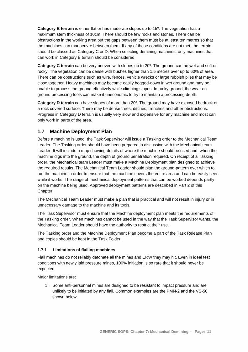
1. Some anti-personnel mines are designed to be resistant to impact pressure and are unlikely to be initiated by any flail. Common examples are the PMN-2 and the VS-50 shown below.
GENERIC SOPS: Chapter 7: Mechanical Demining – Page: 11
2. AG Mines with pin-pull or tilt fuzes may not be detonated by the flail. They may be left in a
damaged condition.
3. Almost all UXO and other ERW will not be reliably initiated by flailing. Some may be left damaged.
NOTE: Staff should not walk in the tracks of any flail machine in areas where AP mines are anticipated.
1.7.2 Limitations of ground tilling and raking machines
Ground tilling and raking machines do not reliably detonate or expose all the mines and ERW that are present. Even in ideal test conditions with newly laid pressure mines, 100% initiation is so rare that it should never be expected.
Major limitations are:
1. In soft ground, devices may be pushed deeper into the ground.
2. In hard ground, devices may be thrown aside by tilling machines.
3. Small mines and the fuzes of larger mines may be missed by the ground engaging tool.
4. AG Mines with pin-pull or tilt fuzes may not be detonated and can be left in a damaged condition.
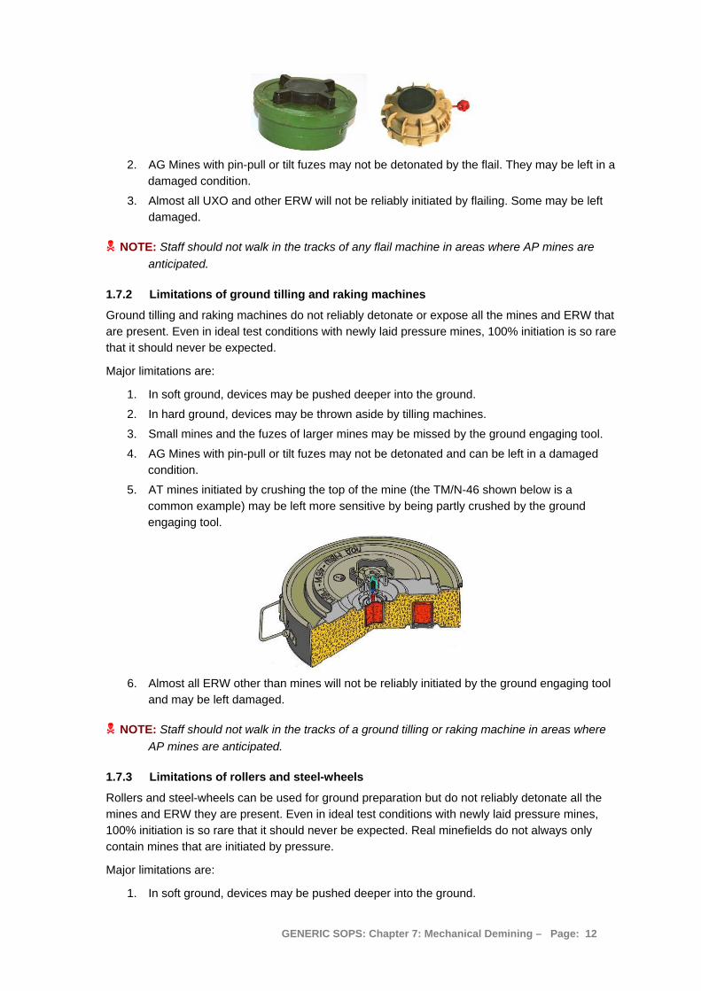
5. AT mines initiated by crushing the top of the mine (the TM/N-46 shown below is a common example) may be left more sensitive by being partly crushed by the ground engaging tool.
6. Almost all ERW other than mines will not be reliably initiated by the ground engaging tool
and may be left damaged.
NOTE: Staff should not walk in the tracks of a ground tilling or raking machine in areas where AP mines are anticipated.
1.7.3 Limitations of rollers and steel-wheels
Rollers and steel-wheels can be used for ground preparation but do not reliably detonate all the mines and ERW they are present. Even in ideal test conditions with newly laid pressure mines, 100% initiation is so rare that it should never be expected. Real minefields do not always only contain mines that are initiated by pressure.
Major limitations are:
1. In soft ground, devices may be pushed deeper into the ground.
GENERIC SOPS: Chapter 7: Mechanical Demining – Page: 12
2. In hard ground, the pressure of the rollers or steel-wheels may not be transferred deep enough to apply pressure to a mine.
3. Rocks and variations in the ground surface can mean that pressure is not applied evenly in all areas.
4. Fragmentation Mines with pin-pull fuzes are unlikely to be detonated by the rollers or steel-wheels. They may be left in a damaged condition.
5. AT mines initiated by crushing the top of the mine (the TM/N-46 is a common example) may be left more sensitive by being partly crushed by the rollers or steel-wheels.
6. Almost all ERW other than mines will not be reliably initiated by the pressure applied by rollers or steel-wheels and may be left damaged.
NOTE: Staff should not walk in the tracks of rollers or steel-wheels in areas where AP mines are anticipated.
1.8 Checking the depth of ground processing Machines with flails or tiller tools that process the ground leave behind ground that is mixed with air and the ground surface is higher than it was before the machine was used. To allow the depth of ground processing inside the SHA/CHA to be reliably determined during QA, the depth of processing must be checked outside the area before the machine is deployed.
The depth of ground processing must be checked in a safe-area with ground conditions similar to those inside the SHA/CHA.
To check the processing depth:
1. Set the tool to the desired depth settings.
2. Process an area 10 metres long using the ground processing tool moving forward at the speed which will be used inside the SHA/CHA.
3. Place a suitably long straight piece of wood or metal across the cut and work it side to side so that it sinks into the disturbed ground and lies flat on the undisturbed ground that is on both sides of the processed ground. This piece of wood or metal is called the “level”.
4. Measure the distance from the bottom of the level to the top of the disturbed ground it is lying across. This is the ground-swell measurement and will be needed when checking performance inside the Task area. Record it on the daily work sheet.
5. Remove the disturbed earth from a place alongside the level until undisturbed ground is found. The flailed ground should be loose and easy to remove by hand.
6. Measure the depth from the undisturbed ground to the bottom of the level. That is the flailing depth at this place. Record it on the daily work sheet.
7. Reposition the level and repeat the depth measurement in five places across the length and the width of the cutting.
The smallest of the five measurements is the reliable ground processing depth at that flail setting at that speed in the ground conditions.
NOTE: If that depth is not enough to reliably strike anticipated AT mines, even machines designed to survive AT mine detonations must not be used in the area because the AT mines may detonate under the wheels or tracks causing severe damage.
1.8.1 Conducting QA on the depth of ground processing
When conducting QA in an area where the ground has been processed, the following procedure should be used:
1. Select an area where the ground is not level whenever possible.
GENERIC SOPS: Chapter 7: Mechanical Demining – Page: 13

2. A breach must be cut using manual demining or MDD Clearance procedures into the processed area.
3. Place a flat piece of wood or metal on the ground to use as a level.
4. Dig the ground alongside the level until undisturbed ground is reached. The processed soil should be loose and easy to remove by hand.
5. Measure the distance from the undisturbed ground to the bottom of the level. This distance, minus the ground-swell measurement that was taken before the machine was used, is the depth of ground processing at that place.
Ground-swell measurement should have been recorded on the daily work sheet for the machine before it was used in the SHA/CHA. If the ground-swell measurement is not available, the depth of ground processing should be recorded as half of the measured depth (actual ground-swell varies widely depending on the composition of the soil).
6. The QA person should repeat this process randomly in at least five places along the breach.
7. The smallest of the five measurements is the reliable ground processing depth that was achieved.
1.9 Using machines for Area Preparation Any machine that removes vegetation or engages the ground can be used in Area Preparation. Area Preparation covers the following:
1. In safe-areas outside the Task area where administration and control areas are established, a machine may be used to remove the vegetation and remove obstacles.
2. In areas inside the SHA/CHA, a machine may be used to cut vegetation without engaging the ground. If the machine enters the SHA/CHA it must be capable of surviving the detonation of any anticipated device under its wheels or tracks without severe injury to its Operator(s).
3. Appropriate machines may be used to crush vegetation and apply pressure on the ground surface as Area Preparation.
4. Land inside the SHA/CHA may be mechanically processed to a recorded depth in preparation for manual demining or MDD procedures to be used as follow up.
5. Suitable machines may be used to remove obstructions from the SHA/CHA (such as fallen trees or vehicle wrecks) in preparation for other assets to be used.
Unless there is no risk of pressure- or tilt-sensitive devices being present, BAC and BACS procedures should not be used after Area Preparation.
1.10 Using machines to locate mined areas Mined areas can be located using any of the available ground processing assets as long as they can be used to process the ground to the required depth at the Task. The depth of processing must be checked outside the SHA/CHA immediately before deployment. The deployment method should ensure that the ground-processing tool remains visible whenever possible, so allowing variations in processing depth to be seen.
If the ground engaging tool rises and falls while it is being used, this indicates that the depth of processing will not be constant. When this occurs, the land should be processed again until there is confidence that the necessary depth has been achieved.
When using steel-wheels or rollers, the entire ground surface must be broken up before the machine moves on. The depth to which pressure has been applied will not be known.
GENERIC SOPS: Chapter 7: Mechanical Demining – Page: 14
To locate a mined area mechanically, breaches are made into the High Threat Areas of the SHA/CHA using the following procedure:
1. Mark a base-line in a safe-area using marking at five metre intervals. 1.2 metre Section pickets or flags may be used to increase the visibility of the marking.
2. Move the machine to the base-line and position any Observers that may be necessary.
3. When a machine is remotely controlled, position the Operator so that they will have a good view of the machine as it works. This is usually best achieved when the Operator is in an MPV.
4. Position any Observers at the correct distances and with appropriate protection.
5. Remove the marking from the area of the base-line where the machine will work.
6. The Mechanical Team Leader must ensure that there are no people inside the appropriate safety-distance for the machine except protected Mechanical Team members.
7. Machines that can enter the SHA/CHA must start ground-processing before they cross the base-line and move forward processing the ground as they enter the SHA/CHA.
Machines that cannot enter the SHA/CHA should be positioned on the safe side of the base-line with their ground processing tool hanging over the SHA/CHA.
8. The deployment pattern for the machine should allow all of the work area to be fully processed.
NOTE: Areas processed by machines are NOT Cleared areas. No one shall walk on ground processed by machines until it has been declared Clear, Reduced, or Verified as having No Known Threat using the procedures described in Chapter 3.
When there are detonations, or devices are exposed, the machine should be withdrawn and should normally approach the High Threat Area again to try to determine the extent of any patterned mine-line(s). The Task Release Plan must be updated to ensure that the detonation areas are Cleared using manual or MDD Clearance procedures. Generally, at least 10 metres on all sides of a detonation or a discovered device must be Cleared.
In areas where there are no detonations or discovered devices during breaching, the machine may be used to process the entire area. The Task Supervisor can then consider applying the criteria for Reduction listed in Chapter 3.
1.11 Using machines for Area Verification When the Task Assessment leads to the conclusion that a part of a Task area has No Known Threat, the area can sometimes be Cancelled without any demining procedures being used. The Cancellation criteria described in Chapter 3, Part 2.5 must be applied. However, even when those criteria would allow Cancellation, the client or end-user must agree. To increase confidence that there is no need to Clear this area, it may be necessary to Verify this decision by processing the area mechanically. This removes all vegetation and may make the end-users of the land more confident that the Task Assessment was correct.
Areas processed mechanically for Verification need not be followed up by any demining procedures. But to raise confidence further, BAC or BACS processes may be conducted in parts of the area. If the area is not covered completely by BAC or BACS processes, it should be released as Verified, not as Reduced by BAC or BACS.
GENERIC SOPS: Chapter 7: Mechanical Demining – Page: 15

1.12 Mechanical Demining Teams The requirements of machines vary and the staff in a Mechanical Demining Team may be changed when necessary.
The minimum Team Personnel are generally:
• Mechanical Team Leader; • Two machine Operator/Observers; • Mechanic for the machine; • Driver for transporting the machine; • Deminer with PPE to be at the Inspection Area when required.
Additional Observers to watch for devices that are thrown aside or exposed are needed with some machines, but are not always a requirement.
A Section of deminers should be available to support the machine if required. When a demining Section is assigned to the machine, the Section Leader should be controlled by the Mechanical Team Leader. The Mechanical Team Leader must always be controlled by the Task Supervisor.
When an MPV accompanies the machine as an Observation or control platform, the MPV driver is a member of the mechanical team to which he/she is attached.
The duties and responsibilities of the Mechanical Demining Team are given in Chapter 1 of these SOPs.
When two or more mechanical demining Teams are assigned to work at a Task at the same time, the Task Supervisor must ensure that their work is integrated and issue appropriate Tasking orders that allow for assets to work together efficiently.
1.13 Action when a machine detonates a device When a machine detonates a device in the SHA/CHA, the Operator must immediately inform the Mechanical Team Leader and withdraw the machine.
1. The machine must be withdrawn over the ground that has been processed and stopped inside the designated Inspection area.
2. After checking as described in Part 1.3.1 in this Chapter, the machine should be inspected for damage and any damaged parts repaired or replaced. When repair will take a significant time, the machine should be withdrawn to a service area so that PPE need not be worn.
3. The Mechanical Team Leader must record the approximate position of the detonation on a map of the working area.
After inspection, an undamaged machine may return to the SHA/CHA to work in an area that is generally at least five metres away from the detonation site. As a general rule, after one device has detonated the machine should not continue to work in the immediate area.
When the machine has been damaged and is unable to withdraw, the machine recovery procedures in Part 1.19 of this Chapter must be followed.
After any detonation that causes damage, the Mechanical Team Leader must review the Machine Deployment Plan. If the machine may be damaged by the detonation of more mines, it should not be used in that area.
GENERIC SOPS: Chapter 7: Mechanical Demining – Page: 16
1.14 Marking detonations and devices When an entire area is to be processed using a machine, the position of any detonations must be marked at the time that they occur. This is usually done by stopping the machine and withdrawing it to approach the area from another direction. The extent of the processed ground then marks the approximate position of the detonation.
When there is a need to continue with the machine, the place where the detonation occurred must be recorded. This can sometimes be done by reference to fixed points close by, such as trees, but usually needs some kind of ground marking to be made. The preferred way to mark the site of a detonation is to use “safe-area reference points”.
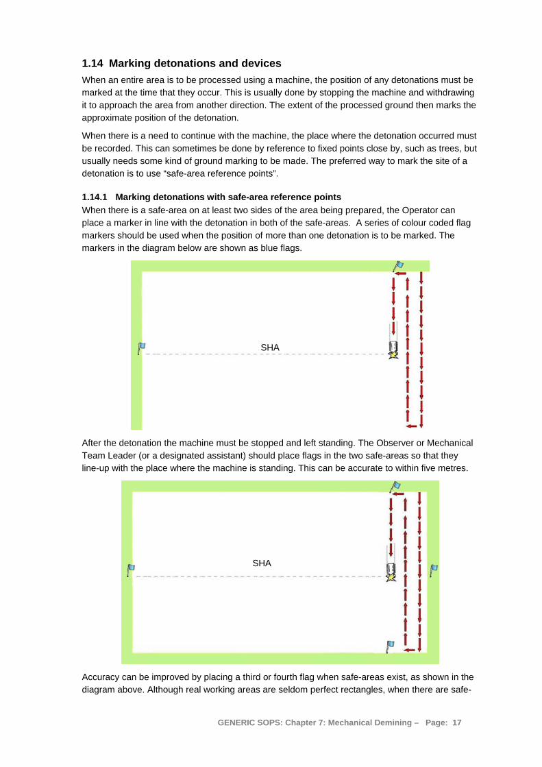
1.14.1 Marking detonations with safe-area reference points When there is a safe-area on at least two sides of the area being prepared, the Operator can place a marker in line with the detonation in both of the safe-areas. A series of colour coded flag markers should be used when the position of more than one detonation is to be marked. The markers in the diagram below are shown as blue flags.
SHA
After the detonation the machine must be stopped and left standing. The Observer or Mechanical Team Leader (or a designated assistant) should place flags in the two safe-areas so that they line-up with the place where the machine is standing. This can be accurate to within five metres.
SHA
Accuracy can be improved by placing a third or fourth flag when safe-areas exist, as shown in the diagram above. Although real working areas are seldom perfect rectangles, when there are safe-
GENERIC SOPS: Chapter 7: Mechanical Demining – Page: 17
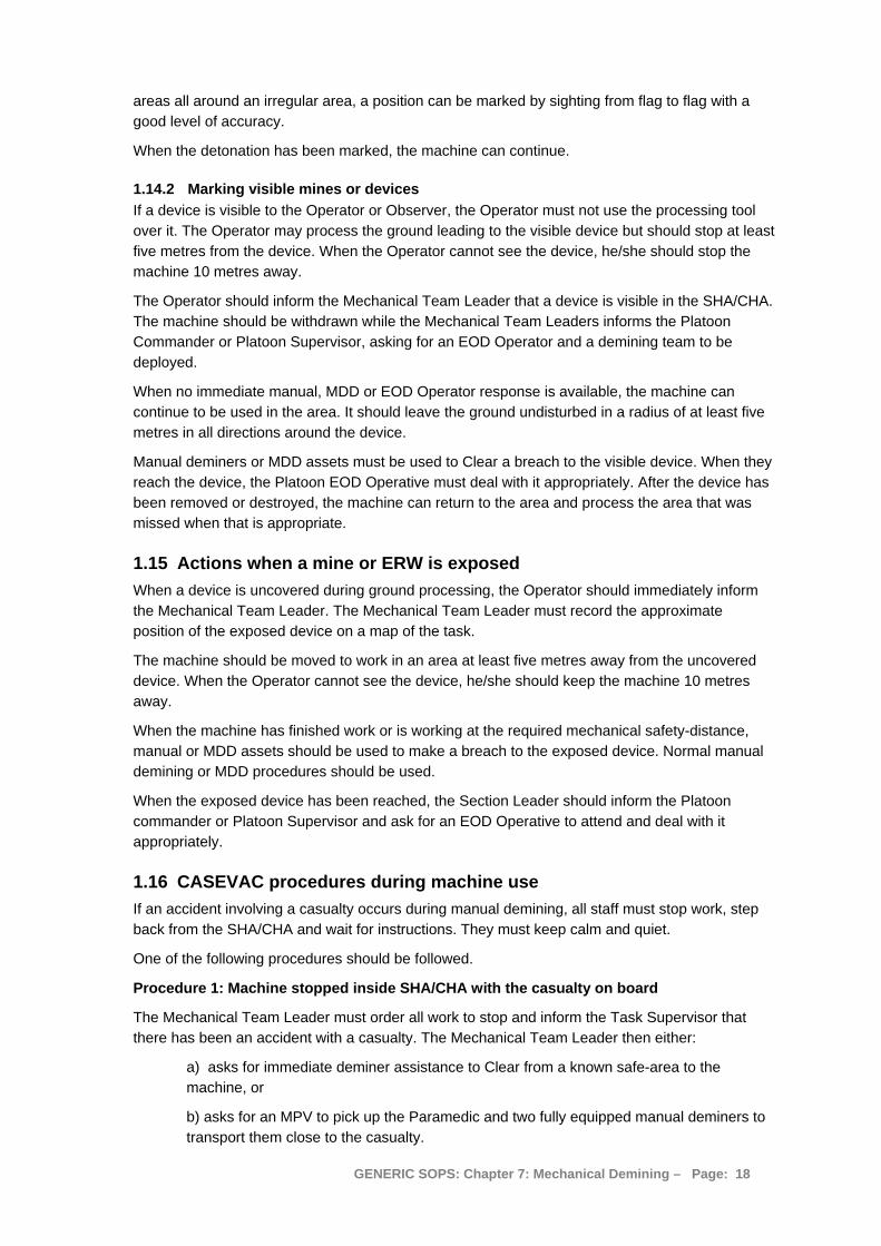
areas all around an irregular area, a position can be marked by sighting from flag to flag with a good level of accuracy.
When the detonation has been marked, the machine can continue.
1.14.2 Marking visible mines or devices If a device is visible to the Operator or Observer, the Operator must not use the processing tool over it. The Operator may process the ground leading to the visible device but should stop at least five metres from the device. When the Operator cannot see the device, he/she should stop the machine 10 metres away.
The Operator should inform the Mechanical Team Leader that a device is visible in the SHA/CHA. The machine should be withdrawn while the Mechanical Team Leaders informs the Platoon Commander or Platoon Supervisor, asking for an EOD Operator and a demining team to be deployed.
When no immediate manual, MDD or EOD Operator response is available, the machine can continue to be used in the area. It should leave the ground undisturbed in a radius of at least five metres in all directions around the device.
Manual deminers or MDD assets must be used to Clear a breach to the visible device. When they reach the device, the Platoon EOD Operative must deal with it appropriately. After the device has been removed or destroyed, the machine can return to the area and process the area that was missed when that is appropriate.
1.15 Actions when a mine or ERW is exposed When a device is uncovered during ground processing, the Operator should immediately inform the Mechanical Team Leader. The Mechanical Team Leader must record the approximate position of the exposed device on a map of the task.
The machine should be moved to work in an area at least five metres away from the uncovered device. When the Operator cannot see the device, he/she should keep the machine 10 metres away.
When the machine has finished work or is working at the required mechanical safety-distance, manual or MDD assets should be used to make a breach to the exposed device. Normal manual demining or MDD procedures should be used.
When the exposed device has been reached, the Section Leader should inform the Platoon commander or Platoon Supervisor and ask for an EOD Operative to attend and deal with it appropriately.
1.16 CASEVAC procedures during machine use If an accident involving a casualty occurs during manual demining, all staff must stop work, step back from the SHA/CHA and wait for instructions. They must keep calm and quiet.
One of the following procedures should be followed.
Procedure 1: Machine stopped inside SHA/CHA with the casualty on board
The Mechanical Team Leader must order all work to stop and inform the Task Supervisor that there has been an accident with a casualty. The Mechanical Team Leader then either:
a) asks for immediate deminer assistance to Clear from a known safe-area to the machine, or
b) asks for an MPV to pick up the Paramedic and two fully equipped manual deminers to transport them close to the casualty.
GENERIC SOPS: Chapter 7: Mechanical Demining – Page: 18
Whenever they hear an unscheduled detonation, any staff working nearby must stop work, stand still and wait for instructions.
When an MPV is available:
a) The Task Supervisor must instruct the MPV driver to drive the machine to the Mechanical Team Leader and follow his/her instructions. The Task Supervisor must call the Paramedic and tell the Ambulance driver to move the vehicle close to the base-line nearest to the casualty. The Paramedic and Ambulance may already have responded.
b) The Mechanical Team Leader should instruct a deminer to bring the stretcher close to the base-line.
c) When the MPV arrives, the Mechanical Team Leader must ensure that the Paramedic, stretcher and two fully equipped deminers are on board, then instruct the driver to drive into the SHA/CHA and stop the MPV beside the damaged machine so that the Paramedic can step across to the damaged machine. When this is not possible or too hazardous, the MPV should stop behind the damaged machine and the two deminers should Clear safe access for the Paramedic to reach the casualty. Appropriate marking must be used to mark the safe access.
d) The Paramedic must stabilize the victim in accordance with appropriate treatment protocols, then ask for the deminers to help remove the victim from the machine and carry him/her to the MPV. The stretcher should be used whenever possible. When all staff and equipment are on board the MPV, it should return to the safe-area and the waiting ambulance.
Procedure two from Step 7 should then be followed.
When no MPV is available, the following variations should be made to the above:
a) The Task Supervisor must make available all assets that will make safe access to the machine as fast as possible. If MDD are available, MDD should generally be used.
b) When safe access to the machine has been achieved, the Paramedic should approach the machine and stabilize the casualty in accordance with appropriate treatment protocols. When the casualty has been stabilised, the Paramedic must ask for two deminers with a stretcher to help remove the casualty from the machine and carry him/her to the safe-area and the waiting ambulance.
Procedure 2: machine standing in safe-area with the casualty on board
1. The Mechanical Team Leader must order all work to stop and inform the Task Supervisor that there has been an accident with a casualty.
2. The Task Supervisor must call the Paramedic and instruct the Ambulance driver to move the vehicle close to the base-line nearest to the casualty. The Paramedic and Ambulance may already have responded. After liaising with the Paramedic and Ambulance, the Task Supervisor should notify the Country office that there has been an accident and that more details will follow.
3. The Mechanical Team Leader should instruct the nearest two Mechanical Team members to go to the casualty and offer moral support and First Aid according to their training. They should not attempt to move the casualty from inside the machine unless it is on fire.
4. The Mechanical Team Leader should instruct another Team member to bring the stretcher to the side of the machine.
5. When the Paramedic arrives he/she will stabilize the casualty in accordance with appropriate treatment protocols, then ask the Mechanical Team members to help remove
GENERIC SOPS: Chapter 7: Mechanical Demining – Page: 19

him/her from the machine and place him/her on the stretcher. All casualties should be put on a stretcher even if their injuries appear to be minor or they appear to be dead.
Generally, the Mechanical Team Leader should go to the casualty after ensuring that the Paramedic and Ambulance are en-route to ensure that all staff are acting in a calm and controlled manner. All accidents are shocking events, and staff who cannot cope must be replaced by people who are less shocked.
6. The Paramedic should supervise the transfer of the casualty to the Ambulance.
7. The Mechanical Team Leader should stay in radio contact with the Task Supervisor and keep him/her informed of all developments.
8. The Task Supervisor must liaise with the ambulance driver and confirm the CASEVAC route to the nearest hospital. The Task Supervisor should also arrange for an escort vehicle to accompany the ambulance with two staff that have a compatible blood group to that of the casualty. Compatible blood groups are listed in Chapter 11 of these SOPs.
9. As soon as the casualty is inside the ambulance, the Task Supervisor should notify the hospital that a casualty is en-route, giving the casualty’s identity, blood-group and an initial assessment of the injuries. The Task Supervisor should stay in contact with the Ambulance and its escort vehicle throughout their journey to hospital. When appropriate, he/she should telephone ahead to arrange fast transit through checkpoints and traffic bottlenecks.
10. When the Casualty has been removed, the accident site must not be disturbed. All staff must be withdrawn to the Administration area, collecting their equipment in an orderly manner. The accident area must be closed off. If equipment is left at the accident site, the task Supervisor should order a guard to be placed when necessary.
No work should be conducted at the Task site until an accident investigation has been completed. Staff should be kept busy with maintenance tasks and kept informed about the condition of the casualty as it becomes known.
11. When all other staff has left the area, the Task Supervisor should carry out an initial investigation of the circumstances surrounding the accident. When they are known, he/she must notify the Country office and request a formal Accident Investigation team to be convened. Generally the Task Supervisor or Platoon Supervisor will be a member of that team.
Procedure 3: Machine moving inside SHA/CHA with the Operator a casualty
1. If the machine is moving inside the SHA/CHA with the injured Operator inside, the Mechanical Team Leader should liaise with the Task Supervisor and send a transport vehicle or MPV to the perimeter of the SHA/CHA where the machine will enter safe ground.
2. When the machine enters safe ground, the rescue machine should move alongside it and allow an Operator or Mechanic to cross onto the machine and stop it. CASEVAC procedures start from the place where the machine stops.
3. Procedure 2 above is then followed.
Procedure 4: Casualty outside the machine and in a safe-area
1. The Mechanical Team Leader must order all work to stop and inform the Task Supervisor that there has been an accident with a casualty.
When the casualty is the Operator who was remotely operating the machine, the Mechanical Team Leader must instruct the second Operator to shut the machine down.
GENERIC SOPS: Chapter 7: Mechanical Demining – Page: 20
2. As long as the casualty has not initiated an explosion personally, the nearest staff should be instructed to go to the casualty and offer moral support and First Aid according to their training.
If the casualty has personally initiated a device outside the SHA/CHA, the Mechanical Team Leader must inform the Task Supervisor and either:
a) ask for immediate deminer assistance to Clear from a known safe-area to the casualty, or b) ask for an MPV to pick up the Paramedic and manual deminers to transport them close to the casualty and Clear access to the casualty.
When the casualty is in a safe-area, the Mechanical Team Leader will generally go to the casualty after ensuring that the Paramedic and Ambulance are en-route.
3. Procedure 2 above from Step 5 is then followed.
Following any accident in which a casualty is taken to hospital, the Task Supervisor must ensure that the casualty receives the appropriate medical care and personal support. The Paramedic should stay with the casualty until the injuries have been assessed and the treatment needs are known. If the casualty must be transferred to another hospital for specialist care, the paramedic should accompany the casualty.
1.16.1 Initial accident investigation The Task Supervisor should conduct an Initial investigation immediately after the accident. During that investigation the accident site should be photographed but left undisturbed. The names of all staff present at the time and involved in the CASEVAC must be noted and a brief description of events surrounding the accident compiled. Generally, formal interviews of witnesses should not be conducted until the Accident Investigation is conducted.
The Task Supervisor should compile the information into a brief report and submit it to the Country Office on the same day as the accident occurs. The Programme Manager should notify the victim’s family, the insurance company and the NMAA.
In case of a fatal accident, the Programme Manager must ensure that the police are informed and that any police investigation is assisted by all Platoon members.
1.17 Encountering wire obstructions The greatest threat to any machine may not be damage by explosive devices. Barbed-wire entanglements, cables and concealed metal or concrete obstructions can cause considerable damage to a machine’s rotating parts. If any such obstruction is encountered by any machine with a rotating tool, the machine should be withdrawn and any damage repaired before it is redeployed to avoid the obstruction. When barbed wire has become entangled in moving parts, it must be removed before the machine is used. The wire can so obstruct movement that severe damage results. Wire or cable can also worm along rotating parts and damage bearings.
Wire and wire fencing is often found inside Task areas. When the Operator of any machine with a rotating tool that engages the ground sees wire, he/she must stop the rotation of the tool and raise it above the ground. If the wire may have become entangled in the rotating tool, the machine must be withdrawn from the SHA/CHA and driven to the Inspection Area for the wire to be removed. Before the wire is removed, the machine must be inspected as described in Part 1.3.1 of this Chapter.
Depending on the tools available, the Mechanical Team Leader may decide to deploy another tool to deliberately remove the wire from the SHA/CHA. If this cannot be done, the area leading up to the wire must be processed using manual or MDD assets and the wire dragged out manually or by attaching it to a machine and pulling it free.
GENERIC SOPS: Chapter 7: Mechanical Demining – Page: 21

NOTE: Wire that has been dragged into a safe area should be inspected by deminers in PPE for any devices that may be entangled among it.
When no means of dealing with the wire is immediately available, the machine may be redeployed in the SHA/CHA, avoiding the area where there is wire.
NOTE: Never use a mechanical tool with wire or cable wrapped around rotating parts.
1.18 When a machine catches fire inside the SHA/CHA The machine’s recommended cleaning and maintenance schedules should mean that it does not catch fire without an outside cause. The outside cause may be damage resulting from the detonation of a mine or ERW.
Under no circumstances should any staff enter an area that is not yet Cleared in order to extinguish a fire on a machine.
When the machine is manned, the Operator should shut down the engine and use the fire extinguisher on board to try to put out the fire.
When the machine is remotely controlled, the Operator should attempt to move the machine into a safe-area where the fire can be extinguished. If that is not possible, the Operator must shut down the engine.
An emergency approach may be made by staff inside a Mine Protected Vehicle. When this is done, all attempts to extinguish the fire should only be made by using fire-fighting equipment from inside the MPV.
If a fire breaks out on a machine inside a SHA/CHA, the following procedure should be followed:
1. The Operator or Observer noticing the fire must report the fire immediately. The Mechanical Team Leader should take control of the situation.
2. The Mechanical Team Leader must notify the Task Supervisor and stop all activity within 150 metres of the machine.
3. If the machine is remotely operated, the Operator should try to drive the machine out of the SHA/CHA where fire-fighting equipment can be safely used. If that is not possible, the Operator must shut down the engine and the Mechanical Team Leader must ask the Task Supervisor for an MPV to be made available.
4. When the Operator is inside the machine, he/she should switch off the engine and use the fire extinguishers to put out the fire.
5. If the Operator needs to evacuate the machine, an MPV should approach the machine to extract the Operator urgently. The MPV should stop alongside the burning machine, close enough for the Operator to step between machines without stepping on the ground.
6. After the evacuation of the Operator, persons inside the MPV can try to extinguish the fire using equipment inside the MPV. They must not leave the MPV when doing so.
7. When no MPV is available and the Operator risks injury by staying with the machine, the Operator must evacuate the machine.
8. Wearing the PPE that is always inside the machine, the Operator must climb over the machine to the back and step into one of the tracks left by the machine as it advanced. If mine-cushions are available, the Operator should take the mine-cushions and drop them from the back of the machine, then step onto them.
9. Taking care to look carefully at the tracks for devices that may have been crushed into the tracks or thrown there and covered with dust, the Operator must avoid hazards and move back to the base-line and the safe-area.
NOTE: A burning machine is not as important as an employee. No one should put their life at risk to try to save the machine.
GENERIC SOPS: Chapter 7: Mechanical Demining – Page: 22

The Task Supervisor may direct manual deminers to Clear an access path to the machine when thee is no risk of its fuel tank(s) exploding. Generally this means that any access route cannot be completed until the fire has burned out.
1.19 Recovering a broken-down or damaged machine If properly maintained, all demining machines should run reliably inside the Task area. If problems occur, the machine should be driven to the Inspection area outside the SHA/CHA.
In the machine breaks down or is damaged so that it cannot move while it is inside the SHA/CHA, all other work within 150 metres of the machine must be stopped. The Mechanical Team Leader must assess the situation and liaise with the Task Supervisor to implement the appropriate Machine Recovery procedures.
The Mechanical Team Leader will already have a Machine Recovery Plan covering predictable situations. The Machine Recovery Plan will include using a Recovery vehicle or making safe access around the machine to allow an assessment to be undertaken where it is.
1.19.1 Using a Recovery vehicle
When a recovery vehicle is available, it should be used to tow the machine out of the SHA/CHA to the designated Inspection Area. When the recovery vehicle is an MPV, it may be used to recover the vehicle without safe access being made at the discretion of the Task Supervisor.
When the recovery machine is not an MPV, a team of manual deminers or MDD must Clear an access route to the machine that is wide enough for the recovery vehicle to use. They must use the working distances, procedures and marking system appropriate for the procedures they use.
When the access route has been Cleared, the deminers must withdraw to the required working distance while the recovery vehicle is driven to the disabled machine and a towing cable attached. The person attaching the towing cable must wear PPE and must not walk on ground that has not been Cleared.
The recovery vehicle should then return to the safe-area towing the damaged machine to a designated Inspection area. Before the machine is inspected for damage, it must be inspected for any devices as described in Part 1.3.1 of this Chapter.
1.19.2 Making safe access around the machine
When no Recovery vehicle is available, manual deminers or MDD must Clear an access route to the machine that is at least two metres wide. They must maintain the working distances, procedures and marking system appropriate for the procedures in use.
When they reach the machine, the Cleared area should be extended to at least three metres on all sides of the machine.
The Cleared area must be marked using an approved marking system so that there is no confusion about which areas have been Cleared.
When the access route and area surrounding the machine have been Cleared, the machine’s mechanic can approach it and assess the damage. The mechanic must wear PPE at all times while inside the SHA/CHA. If the machine can be repaired where it is, and without getting under it, the repair should be conducted and the machine driven to the designated Inspection Area and inspected as described in Part 1.3.1 of this Chapter. If the machine cannot be repaired where it is, it should be made secure and left for later recovery using a Recovery vehicle.
When the damaged machine is removed, the ground where it stood should be marked and Cleared using manual or MDD assets.
GENERIC SOPS: Chapter 7: Mechanical Demining – Page: 23
2. Management of mechanical demining operations By integrating mechanical demining with manual and MDD procedures, the Task Release Plan should ensure that all parts of the Task are appropriately processed in preparation for the Release of the entire Task site. The Task Release Plan should ensure efficiency in terms of safety, speed and cost.
To evaluate the advantages of using machines, the Task Supervisor and Mechanical Team Leader must have the following information about all machines:
1. the machine’s ability to work over: • sloping ground; • wet ground; • hard ground; • rocky ground; • dense vegetation; and • its operating temperatures;
2. the explosive hazards that the machine can be expected to withstand;
3. the ideal operating conditions for the machine; and
4. the effectiveness of the machine in disrupting, or detonating the different types of mines and ERW anticipated.
Although manufacturers make some claims for their machines, such claims have not always proven reliable. Operational information about each machine should be collected during machine use and collated for analysis that will inform future use.
2.1 Deployment limitations When planning for machine use, the Task Supervisor must bear in mind the following limitations on deployment. With larger machines, the limitations may make the use of the machine impractical.
1. The roads and bridges along which the machine will travel to the Task;
2. the maintenance and repair facilities available in the Task area;
3. the fuel and maintenance requirements of the machine; and
4. possible damage to property or infrastructure by the machine.
When planning the repair, maintenance and servicing of the machines, care must be taken to prevent ground and watercourse contamination from fuel, oil and lubricants.
2.2 Mechanical tasking orders Mechanical Teams may be moved between Task sites. When a Mechanical Team arrives at a Task, the Task Supervisor should provide the Mechanical Team Leader with Tasking orders that include a detailed map showing the areas that must be processed, each of which is given an Area ID number on the map.
The Mechanical Team Leader must assess the various tasks and reports back to the Task Supervisor if any of them are not appropriate for the deployment of the machine. The Mechanical Team Leader has ultimate responsibility for the Mechanical Team and the machine, and must not agree to use the machine in areas where it will be unnecessarily damaged or where staff will be exposed to unnecessary risk.
The Mechanical Team Leader uses the Tasking Order and a site assessment to compile a Machine Deployment Plan that will make maximum use of the machine’s capabilities. The
GENERIC SOPS: Chapter 7: Mechanical Demining – Page: 24
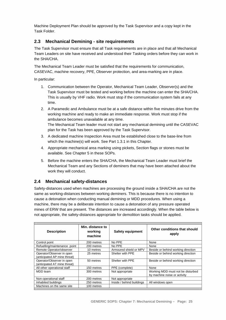
Machine Deployment Plan should be approved by the Task Supervisor and a copy kept in the Task Folder.
2.3 Mechanical Demining - site requirements The Task Supervisor must ensure that all Task requirements are in place and that all Mechanical Team Leaders on site have received and understood their Tasking orders before they can work in the SHA/CHA.
The Mechanical Team Leader must be satisfied that the requirements for communication, CASEVAC, machine recovery, PPE, Observer protection, and area-marking are in place.
In particular:
1. Communication between the Operator, Mechanical Team Leader, Observer(s) and the Task Supervisor must be tested and working before the machine can enter the SHA/CHA. This is usually by VHF radio. Work must stop if the communication system fails at any time.
2. A Paramedic and Ambulance must be at a safe distance within five minutes drive from the working machine and ready to make an immediate response. Work must stop if the ambulance becomes unavailable at any time. The Mechanical Team leader must not start any mechanical demining until the CASEVAC plan for the Task has been approved by the Task Supervisor.
3. A dedicated machine Inspection Area must be established close to the base-line from which the machine(s) will work. See Part 1.3.1 in this Chapter.
4. Appropriate mechanical area marking using pickets, Section flags or stones must be available. See Chapter 5 in these SOPs.
5. Before the machine enters the SHA/CHA, the Mechanical Team Leader must brief the Mechanical Team and any Sections of deminers that may have been attached about the work they will conduct.
2.4 Mechanical safety-distances Safety-distances used when machines are processing the ground inside a SHA/CHA are not the same as working-distances between working deminers. This is because there is no intention to cause a detonation when conducting manual demining or MDD procedures. When using a machine, there may be a deliberate intention to cause a detonation of any pressure operated mines of ERW that are present. The distances are increased accordingly. When the table below is not appropriate, the safety-distances appropriate for demolition tasks should be applied.
Description Min. distance to
working machine
Safety equipment Other conditions that should apply
Control point 200 metres No PPE None Refuelling/maintenance point 200 metres No PPE None Remote Operator/observer 10 metres Armoured shield or MPV Beside or behind working direction Operator/Observer in open (anticipated AP mine threat)
25 metres Shelter with PPE Beside or behind working direction
Operator/Observer in open (anticipated AT mine threat)
50 metres Shelter with PPE Beside or behind working direction
All other operational staff 150 metres PPE (complete) None MDD team 300 metres Not appropriate Working MDD must not be disturbed
by machine noise or activity Non-operational staff 200 metres Not appropriate Inhabited buildings 250 metres Inside / behind buildings All windows open Machines on the same site 100 metres
GENERIC SOPS: Chapter 7: Mechanical Demining – Page: 25
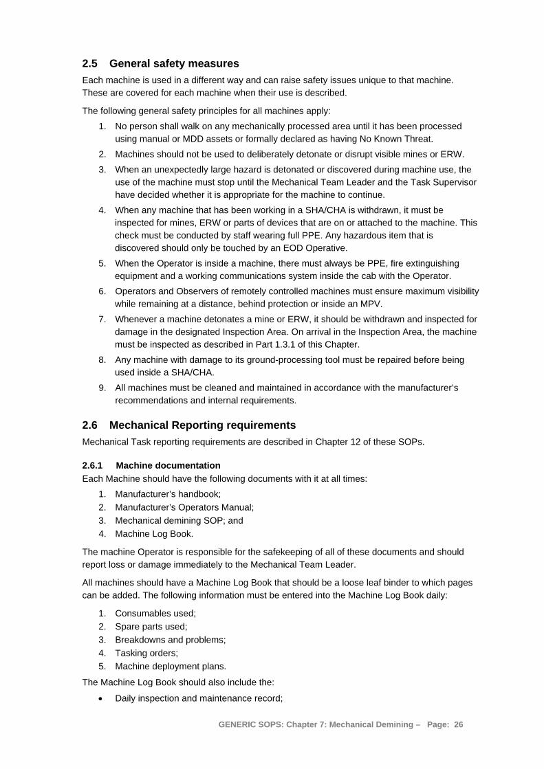
2.5 General safety measures Each machine is used in a different way and can raise safety issues unique to that machine. These are covered for each machine when their use is described.
The following general safety principles for all machines apply:
1. No person shall walk on any mechanically processed area until it has been processed using manual or MDD assets or formally declared as having No Known Threat.
2. Machines should not be used to deliberately detonate or disrupt visible mines or ERW.
3. When an unexpectedly large hazard is detonated or discovered during machine use, the use of the machine must stop until the Mechanical Team Leader and the Task Supervisor have decided whether it is appropriate for the machine to continue.
4. When any machine that has been working in a SHA/CHA is withdrawn, it must be inspected for mines, ERW or parts of devices that are on or attached to the machine. This check must be conducted by staff wearing full PPE. Any hazardous item that is discovered should only be touched by an EOD Operative.
5. When the Operator is inside a machine, there must always be PPE, fire extinguishing equipment and a working communications system inside the cab with the Operator.
6. Operators and Observers of remotely controlled machines must ensure maximum visibility while remaining at a distance, behind protection or inside an MPV.
7. Whenever a machine detonates a mine or ERW, it should be withdrawn and inspected for damage in the designated Inspection Area. On arrival in the Inspection Area, the machine must be inspected as described in Part 1.3.1 of this Chapter.
8. Any machine with damage to its ground-processing tool must be repaired before being used inside a SHA/CHA.
9. All machines must be cleaned and maintained in accordance with the manufacturer’s recommendations and internal requirements.
2.6 Mechanical Reporting requirements Mechanical Task reporting requirements are described in Chapter 12 of these SOPs.
2.6.1 Machine documentation Each Machine should have the following documents with it at all times:
1. Manufacturer’s handbook; 2. Manufacturer’s Operators Manual; 3. Mechanical demining SOP; and 4. Machine Log Book.
The machine Operator is responsible for the safekeeping of all of these documents and should report loss or damage immediately to the Mechanical Team Leader.
All machines should have a Machine Log Book that should be a loose leaf binder to which pages can be added. The following information must be entered into the Machine Log Book daily:
1. Consumables used; 2. Spare parts used; 3. Breakdowns and problems; 4. Tasking orders; 5. Machine deployment plans.
The Machine Log Book should also include the:
• Daily inspection and maintenance record;
GENERIC SOPS: Chapter 7: Mechanical Demining – Page: 26
• Weekly inspection and maintenance record; and • Monthly inspection and maintenance record.
These should be kept in accordance with the manufacturers recommendations. Copies of the Inspection and maintenance records, Tasking orders, and Machine Deployment plans should be sent to the Country office every month.
3. Using converted excavators Converted excavating machinery that has been modified and appropriately armoured may be used. The essential features of a converted excavator are:
1. The cabin must armoured to protect the Operator against the effects of an AP fragmentation mine detonation or greater.
2. All the cylinders, fuel tank and the hydraulic tank must be blast and fragmentation protected.
3. Tools that can be attached should be designed to get into small areas where other machines cannot reach, such as trenches, ditches, canals, bridges, culverts, dry river banks, shallow water, around trees and around destroyed buildings and rubble.
4. Tools should be changed using a “Quick Change” device that makes it simple and fast to change the tools at the end of the hydraulic arm.
The following limitations must be considered when planning to use of a converted excavator:
1. The machine must not be used in areas where AT mines are anticipated unless genuinely armoured against that threat. After-market armouring does not normally protect the Operator or the machine from large blasts.
2. The machine should not be used in areas where the ground slopes more than 30° unless measures are taken to ensure its stability.
3. The base machine is not designed for extended use processing wide areas of ground. While it may be used to do so, the operating times should comply with the recommended use in the manufacturer’s guidelines.
4. The machine has no built-in recovery system. When using the machine in a SHA/CHA, a recovery system capable of recovering the machine (plus the weight of its tool) should be at the Task site.
When the machine is used inside the Task area, a Mine Protected Vehicle (MPV) should accompany the machine to ensure safe recovery in the event of breakdown and provide a mobile observation platform. When an MPV is not available, protective shelters should be provided for Observer and support staff whenever possible.
From previous experience (and depending on machine size), 4-8m² of land may be processed to 15cm depth for each litre of fuel. When planning deployment, the machine Operator should be consulted about realistic fuel consumption and performance using the various tools.
The machine may work on steeply sloping ground as long as the base-unit can be positioned in a stable manner. Depending on the tools used, it can process wet, hard or rocky ground. With the correct vegetation removal tools, it can remove mature vegetation.
The operating temperatures for the machine must be taken from the manufacturer’s handbook with allowances made for any reduction in air-cooling made by the after-market application of armoured panels.
GENERIC SOPS: Chapter 7: Mechanical Demining – Page: 27

Depending on the tool, the excavator may be expected to expose or to detonate discovered pressure devices. When used to expose devices, additional Observers may be required to ensure that uncovered devices are seen.
3.1 Excavator tool attachments Converted excavators may have a range of tools that can be attached to their hydraulic arms for performing varied procedures inside the Task area as described below. The range and the size of each tool will depend on the power available to drive them. Generally, the larger the base machine the larger the working tools can be. The advantage of large tools has to be weighed against the disadvantage of increased weight (affecting transportation and work on soft ground) and increased fuel consumption.
Approved tools are:
• A rotary cutter attachment that concentrates the available power to drive a small cutting tool so allowing the machine to be effective in very hard or rocky ground and in dense vegetation. The tool should have a maximum digging depth of at least 5cm more than the national Clearance requirement and the tool head should dig across as wide an area as available power permits.
• A hydraulic flail (with short chains or shaped chisels) as wide as the available power permits for use in light vegetation and ground without rocks.
• A standard excavator bucket. The bucket’s main uses are in digging out collapsed trenches, roadside ditches and for spreading the rubble of ruined buildings for subsequent search.
• A Sifting bucket. This is a grid-mesh bucket that has been designed to allow loose soil to fall through the bucket while large objects remain. Its main use is for sifting soil that has been removed from hazardous areas. In soft ground, it can also be used to dig inside hazardous areas.
• The Arjun rake is a large-tined rake attachments designed to rake the ground to depths up to 30cm and lift large concealed devices to the surface. Depending on the power available, it can effectively remove mature vegetation and roots from the working area, placing them to the rear for searching using manual or MDD procedures.
A drawing of the Arjun rake is shown alongside.
GENERIC SOPS: Chapter 7: Mechanical Demining – Page: 28
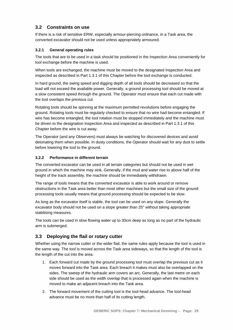
3.2 Constraints on use If there is a risk of sensitive ERW, especially armour-piercing ordnance, in a Task area, the converted excavator should not be used unless appropriately armoured.
3.2.1 General operating rules
The tools that are to be used in a task should be positioned in the Inspection Area conveniently for tool exchange before the machine is used.
When tools are exchanged, the machine must be moved to the designated Inspection Area and inspected as described in Part 1.3.1 of this Chapter before the tool exchange is conducted.
In hard ground, the swing speed and digging depth of all tools should be decreased so that the load will not exceed the available power. Generally, a ground processing tool should be moved at a slow consistent speed through the ground. The Operator must ensure that each cut made with the tool overlaps the previous cut.
Rotating tools should be spinning at the maximum permitted revolutions before engaging the ground. Rotating tools must be regularly checked to ensure that no wire had become entangled. If wire has become entangled, the tool rotation must be stopped immediately and the machine must be driven to the designation Inspection Area and inspected as described in Part 1.3.1 of this Chapter before the wire is cut away.
The Operator (and any Observers) must always be watching for discovered devices and avoid detonating them when possible. In dusty conditions, the Operator should wait for any dust to settle before lowering the tool to the ground.
3.2.2 Performance in different terrain
The converted excavator can be used in all terrain categories but should not be used in wet ground in which the machine may sink. Generally, if the mud and water rise to above half of the height of the track assembly, the machine should be immediately withdrawn.
The range of tools means that the converted excavator is able to work around or remove obstructions in the Task area better than most other machines but the small size of the ground processing tools usually means that ground processing should be expected to be slow.
As long as the excavator itself is stable, the tool can be used on any slope. Generally the excavator body should not be used on a slope greater than 25° without taking appropriate stabilising measures.
The tools can be used in slow flowing water up to 30cm deep as long as no part of the hydraulic arm is submerged.
3.3 Deploying the flail or rotary cutter Whether using the narrow cutter or the wider flail, the same rules apply because the tool is used in the same way. The tool is moved across the Task area sideways, so that the length of the tool is the length of the cut into the area.
1. Each forward cut made by the ground processing tool must overlap the previous cut as it moves forward into the Task area. Each breach it makes must also be overlapped on the sides. The sweep of the hydraulic arm covers an arc. Generally, the last metre on each side should be used as the width overlap that is processed again when the machine is moved to make an adjacent breach into the Task area.
2. The forward movement of the cutting tool is the tool-head advance. The tool-head advance must be no more than half of its cutting length.
GENERIC SOPS: Chapter 7: Mechanical Demining – Page: 29
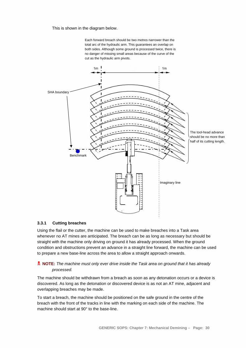
This is shown in the diagram below.
Each forward breach should be two metres narrower than the total arc of the hydraulic arm. This guarantees an overlap on both sides. Although some ground is processed twice, there is no danger of missing small areas because of the curve of the cut as the hydraulic arm pivots.
Benchmark
SHA boundary
The tool-head advance should be no more than half of its cutting length.
Imaginary line
3.3.1 Cutting breaches
Using the flail or the cutter, the machine can be used to make breaches into a Task area whenever no AT mines are anticipated. The breach can be as long as necessary but should be straight with the machine only driving on ground it has already processed. When the ground condition and obstructions prevent an advance in a straight line forward, the machine can be used to prepare a new base-line across the area to allow a straight approach onwards.
NOTE: The machine must only ever drive inside the Task area on ground that it has already processed.
The machine should be withdrawn from a breach as soon as any detonation occurs or a device is discovered. As long as the detonation or discovered device is as not an AT mine, adjacent and overlapping breaches may be made.
To start a breach, the machine should be positioned on the safe ground in the centre of the breach with the front of the tracks in line with the marking on each side of the machine. The machine should start at 90° to the base-line.
GENERIC SOPS: Chapter 7: Mechanical Demining – Page: 30
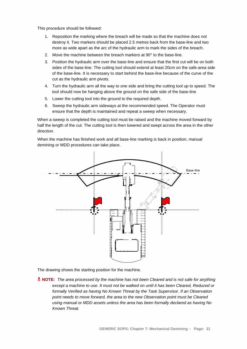
This procedure should be followed:
1. Reposition the marking where the breach will be made so that the machine does not destroy it. Two markers should be placed 2.5 metres back from the base-line and two more as wide apart as the arc of the hydraulic arm to mark the sides of the breach.
2. Move the machine between the breach markers at 90° to the base-line.
3. Position the hydraulic arm over the base-line and ensure that the first cut will be on both sides of the base-line. The cutting tool should extend at least 20cm on the safe-area side of the base-line. It is necessary to start behind the base-line because of the curve of the cut as the hydraulic arm pivots.
4. Turn the hydraulic arm all the way to one side and bring the cutting tool up to speed. The tool should now be hanging above the ground on the safe side of the base-line
5. Lower the cutting tool into the ground to the required depth.
6. Sweep the hydraulic arm sideways at the recommended speed. The Operator must ensure that the depth is maintained and repeat a sweep when necessary.
When a sweep is completed the cutting tool must be raised and the machine moved forward by half the length of the cut. The cutting tool is then lowered and swept across the area in the other direction.
When the machine has finished work and all base-line marking is back in position, manual demining or MDD procedures can take place.
Base-line
The drawing shows the starting position for the machine.
NOTE: The area processed by the machine has not been Cleared and is not safe for anything except a machine to use. It must not be walked on until it has been Cleared, Reduced or formally Verified as having No Known Threat by the Task Supervisor. If an Observation point needs to move forward, the area to the new Observation point must be Cleared using manual or MDD assets unless the area has been formally declared as having No Known Threat.
GENERIC SOPS: Chapter 7: Mechanical Demining – Page: 31

3.3.2 Cutting adjacent breaches
By cutting breaches alongside each other, a wide area can be processed. Each consecutive breach must be marked at regular intervals along the SHA/CHA perimeter. The marking is moved back 2.5 metres as the machine progresses. Marking should only be moved when the machine is standing inside the safe-area with the ground processing tool raised above the ground.
When a breach has been processed, the Operator moves the machine to the centre of the next breach and repeats the procedure. While the machine is standing still inside the safe-area, one base-line marker can be replaced in its forward position while another on the line is moved back
The drawing shows how markers should be moved back and forward as the machine progresses.
When the machine has finished work and all base-line marking is back in position, manual demining or MDD procedures can take place.
NOTE: The depth of ground processing should be greater than the depth of suspected hazards. When this is not known, 20cm should be the minimum unless the machine is only being used to remove vegetation (when it must not drive into the Task area at all).
3.3.3 Cutting spaced breaches
Using the flail or the rotary cutter, the machine can be used to make breaches into a Task area where no AT mines are expected. The breaches can be as long as necessary but should be straight. The breach cutting procedure described in Part 3.4.1 above should be followed.
Breaches are generally cut at distances of 20 metres but this can be varied to suit the Task Release Plan. They may be as long as required but the machine must be withdrawn from each breach as soon as a detonation occurs.
Marker replaced One marker replaced
Current breach,one marker moved back
Machine moving into position
Original base-line and start-line
Mechanical breach lanes
Areas between lanes must be processed appropriately as described in Chapter 3.
SHA
New base-line
Detonations
GENERIC SOPS: Chapter 7: Mechanical Demining – Page: 32
3.3.4 Processing road verges mechanically
Road verges can be processed with the converted excavator as shown below. The Task Assessment must have determined that there are no AT mines present.
Marking may use Section pickets or painted stones. Stones are sometimes more appropriate on road surfaces, but they can be hard to see in dusty conditions.
3.3.5 Using the excavation bucket in the Task area
There are areas where the most efficient method of Clearance will be to lift soil or building rubble out of the Task area and inspect it in a safe-area. Examples are collapsed trenches or ditches and around damaged buildings. The method is sometimes useful for the ditches on road verges or for short lengths of road verge.
The Operator should do the following:
1. Position the tracks of the machine parallel to the base-line and at least a metre away from the base-line.
2. Extend the hydraulic arm over the Task area and dig into the soil to the required depth, then scoop backwards with an even sweep. The area excavated should be flat and free from loose soil.
3. The Operator should then swing the hydraulic arm over the safe-area and dump the excavated material in the soil inspection area. The bucket may be used to spread the load out evenly to a thickness not more than 15cm.
4. The Operator should watch carefully for obvious mines and ERW as the bucket is emptied and spread out. If a suspicious item is seen, he/she must stop work until the manual demining team have Cleared up to the item and an EOD Operative has dealt with it.
5. The Operator then swings the hydraulic arm over the Task area and digs into the soil to the required depth again.
6. This process is repeated until the soil inspection area is covered with loose earth not more than 15cm deep.
When something prevents the excavation being deep enough, the area must be marked at the base-line and Cleared later using manual of MDD Clearance processes. The Operator should position the hydraulic arm over the safe-area while the Observer places three white stones or pickets as a marker on the base-line. It is often not possible to reach the required depth around trees, large rocks or vehicle wrecks.
GENERIC SOPS: Chapter 7: Mechanical Demining – Page: 33

When the machine has withdrawn or is working at its safety-distance, the area around the obstacle must be Cleared manually or with MDD. When it has been Cleared, the three stones of pickets should be removed and a white circle should be painted on the ground that was Cleared. This makes it easy to distinguish between obstacles waiting to be Cleared and those which have been Cleared. White circles should be used to mark Cleared areas in long linear tasks where many small areas may require manual or MDD Clearance.
3.3.6 Clearing the soil in the Inspection areas
An area free from metal must be prepared and marked to serve as the soil inspection area. When metal-detectors are used, this area should be declared metal-free before it is used. When the REDS is used, the area need not be metal-free. The machine should spread the excavated soil out evenly using the bucket in the following procedure:
1. The heaps of soil should be dumped alongside each other and parallel to the base-line.
2. The Operator should lower the bucket and use the bucket teeth to “rake” the soil backwards. It should be spread evenly to a depth of not more than 15cm.
When the machine has withdrawn, or is working at its safety-distance the manual demining team must recheck the access lanes and safe lanes over which the machine moved the bucket. Any spilled soil must be searched.
Inspection area
When the access lane has been checked, deminers using metal detectors or rakes must manually search the soil inspection area using marked lanes and working distances as in any other SHA/CHA. When rakes are used, all the soil must be raked through using lanes as described in Chapter 6, Part 9 of these SOPs. When metal-detectors are used, the entire area must be searched and left metal-free using the procedures described in Chapter 6, Part 7 of these SOPs.
NOTE: MDDs should not be used to check the soil inspection area unless it is left undisturbed for at least a week and the MDD Coordinator is satisfied that the correct conditions apply and that the MDD Sets have been appropriately prepared.
The soil is loose and there is no vegetation, so progress can be very rapid but all safety measures must be taken as with demining in any other SHA. Roots and rubbish should be removed and piled in a designated area for later burning or burial.
GENERIC SOPS: Chapter 7: Mechanical Demining – Page: 34
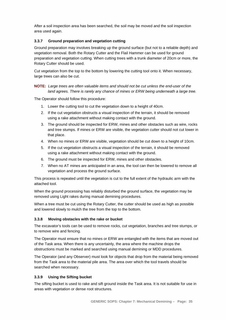
After a soil inspection area has been searched, the soil may be moved and the soil inspection area used again.
3.3.7 Ground preparation and vegetation cutting
Ground preparation may involves breaking up the ground surface (but not to a reliable depth) and vegetation removal. Both the Rotary Cutter and the Flail Hammer can be used for ground preparation and vegetation cutting. When cutting trees with a trunk diameter of 20cm or more, the Rotary Cutter should be used.
Cut vegetation from the top to the bottom by lowering the cutting tool onto it. When necessary, large trees can also be cut.
NOTE: Large trees are often valuable items and should not be cut unless the end-user of the land agrees. There is rarely any chance of mines or ERW being underneath a large tree.
The Operator should follow this procedure:
1. Lower the cutting tool to cut the vegetation down to a height of 40cm.
2. If the cut vegetation obstructs a visual inspection of the terrain, it should be removed using a rake attachment without making contact with the ground.
3. The ground should be inspected for ERW, mines and other obstacles such as wire, rocks and tree stumps. If mines or ERW are visible, the vegetation cutter should not cut lower in that place.
4. When no mines or ERW are visible, vegetation should be cut down to a height of 10cm.
5. If the cut vegetation obstructs a visual inspection of the terrain, it should be removed using a rake attachment without making contact with the ground.
6. The ground must be inspected for ERW, mines and other obstacles.
7. When no AT mines are anticipated in an area, the tool can then be lowered to remove all vegetation and process the ground surface.
This process is repeated until the vegetation is cut to the full extent of the hydraulic arm with the attached tool.
When the ground processing has reliably disturbed the ground surface, the vegetation may be removed using Light rakes during manual demining procedures.
When a tree must be cut using the Rotary Cutter, the cutter should be used as high as possible and lowered slowly to mulch the tree from the top to the bottom.
3.3.8 Moving obstacles with the rake or bucket
The excavator’s tools can be used to remove rocks, cut vegetation, branches and tree stumps, or to remove wire and fencing.
The Operator must ensure that no mines or ERW are entangled with the items that are moved out of the Task area. When there is any uncertainly, the area where the machine drops the obstructions must be marked and searched using manual demining or MDD procedures.
The Operator (and any Observer) must look for objects that drop from the material being removed from the Task area to the material pile area. The area over which the tool travels should be searched when necessary.
3.3.9 Using the Sifting bucket
The sifting bucket is used to rake and sift ground inside the Task area. It is not suitable for use in areas with vegetation or dense root structures.
GENERIC SOPS: Chapter 7: Mechanical Demining – Page: 35
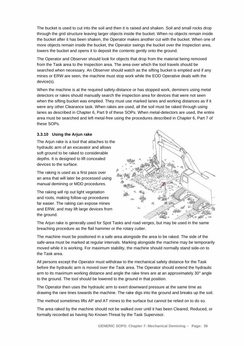
The bucket is used to cut into the soil and then it is raised and shaken. Soil and small rocks drop through the grid structure leaving larger objects inside the bucket. When no objects remain inside the bucket after it has been shaken, the Operator makes another cut with the bucket. When one of more objects remain inside the bucket, the Operator swings the bucket over the Inspection area, lowers the bucket and opens it to deposit the contents gently onto the ground.
The Operator and Observer should look for objects that drop from the material being removed from the Task area to the Inspection area. The area over which the tool travels should be searched when necessary. An Observer should watch as the sifting bucket is emptied and if any mines or ERW are seen, the machine must stop work while the EOD Operative deals with the device(s).
When the machine is at the required safety-distance or has stopped work, deminers using metal detectors or rakes should manually search the inspection area for devices that were not seen when the sifting bucket was emptied. They must use marked lanes and working distances as if it were any other Clearance task. When rakes are used, all the soil must be raked through using lanes as described in Chapter 6, Part 9 of these SOPs. When metal-detectors are used, the entire area must be searched and left metal-free using the procedures described in Chapter 6, Part 7 of these SOPs.
3.3.10 Using the Arjun rake
The Arjun rake is a tool that attaches to the hydraulic arm of an excavator and allows soft ground to be raked to considerable depths. It is designed to lift concealed devices to the surface.
The raking is used as a first pass over an area that will later be processed using manual demining or MDD procedures.
The raking will rip out light vegetation and roots, making follow-up procedures far easier. The raking can expose mines and ERW, and may lift large devices from the ground.
The Arjun rake is generally used for Spot Tasks and road verges, but may be used in the same breaching procedure as the flail hammer or the rotary cutter.
The machine must be positioned in a safe area alongside the area to be raked. The side of the safe-area must be marked at regular intervals. Marking alongside the machine may be temporarily moved while it is working. For maximum stability, the machine should normally stand side-on to the Task area.
All persons except the Operator must withdraw to the mechanical safety distance for the Task before the hydraulic arm is moved over the Task area. The Operator should extend the hydraulic arm to its maximum working distance and angle the rake tines are at an approximately 30° angle to the ground. The tool should be lowered to the ground in that position.
The Operator then uses the hydraulic arm to exert downward pressure at the same time as drawing the rare tines towards the machine. The rake digs into the ground and breaks up the soil.
The method sometimes lifts AP and AT mines to the surface but cannot be relied on to do so.
The area raked by the machine should not be walked over until it has been Cleared, Reduced, or formally recorded as having No Known Threat by the Task Supervisor.
GENERIC SOPS: Chapter 7: Mechanical Demining – Page: 36
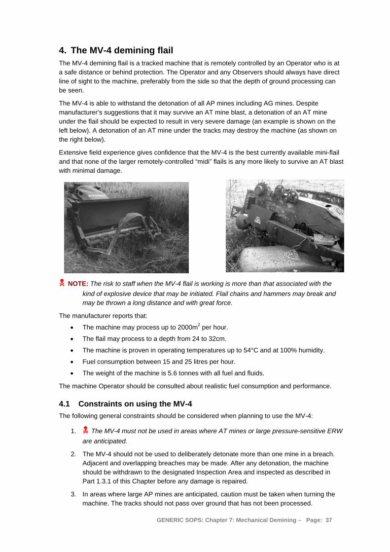
4. The MV-4 demining flail The MV-4 demining flail is a tracked machine that is remotely controlled by an Operator who is at a safe distance or behind protection. The Operator and any Observers should always have direct line of sight to the machine, preferably from the side so that the depth of ground processing can be seen.
The MV-4 is able to withstand the detonation of all AP mines including AG mines. Despite manufacturer’s suggestions that it may survive an AT mine blast, a detonation of an AT mine under the flail should be expected to result in very severe damage (an example is shown on the left below). A detonation of an AT mine under the tracks may destroy the machine (as shown on the right below).
Extensive field experience gives confidence that the MV-4 is the best currently available mini-flail and that none of the larger remotely-controlled “midi” flails is any more likely to survive an AT blast with minimal damage.
NOTE: The risk to staff when the MV-4 flail is working is more than that associated with the kind of explosive device that may be initiated. Flail chains and hammers may break and may be thrown a long distance and with great force.
The manufacturer reports that:
• The machine may process up to 2000m2 per hour.
• The flail may process to a depth from 24 to 32cm.
• The machine is proven in operating temperatures up to 54°C and at 100% humidity.
• Fuel consumption between 15 and 25 litres per hour.
• The weight of the machine is 5.6 tonnes with all fuel and fluids.
The machine Operator should be consulted about realistic fuel consumption and performance.
4.1 Constraints on using the MV-4 The following general constraints should be considered when planning to use the MV-4:
1. The MV-4 must not be used in areas where AT mines or large pressure-sensitive ERW are anticipated.
2. The MV-4 should not be used to deliberately detonate more than one mine in a breach. Adjacent and overlapping breaches may be made. After any detonation, the machine should be withdrawn to the designated Inspection Area and inspected as described in Part 1.3.1 of this Chapter before any damage is repaired.
3. In areas where large AP mines are anticipated, caution must be taken when turning the machine. The tracks should not pass over ground that has not been processed.
GENERIC SOPS: Chapter 7: Mechanical Demining – Page: 37
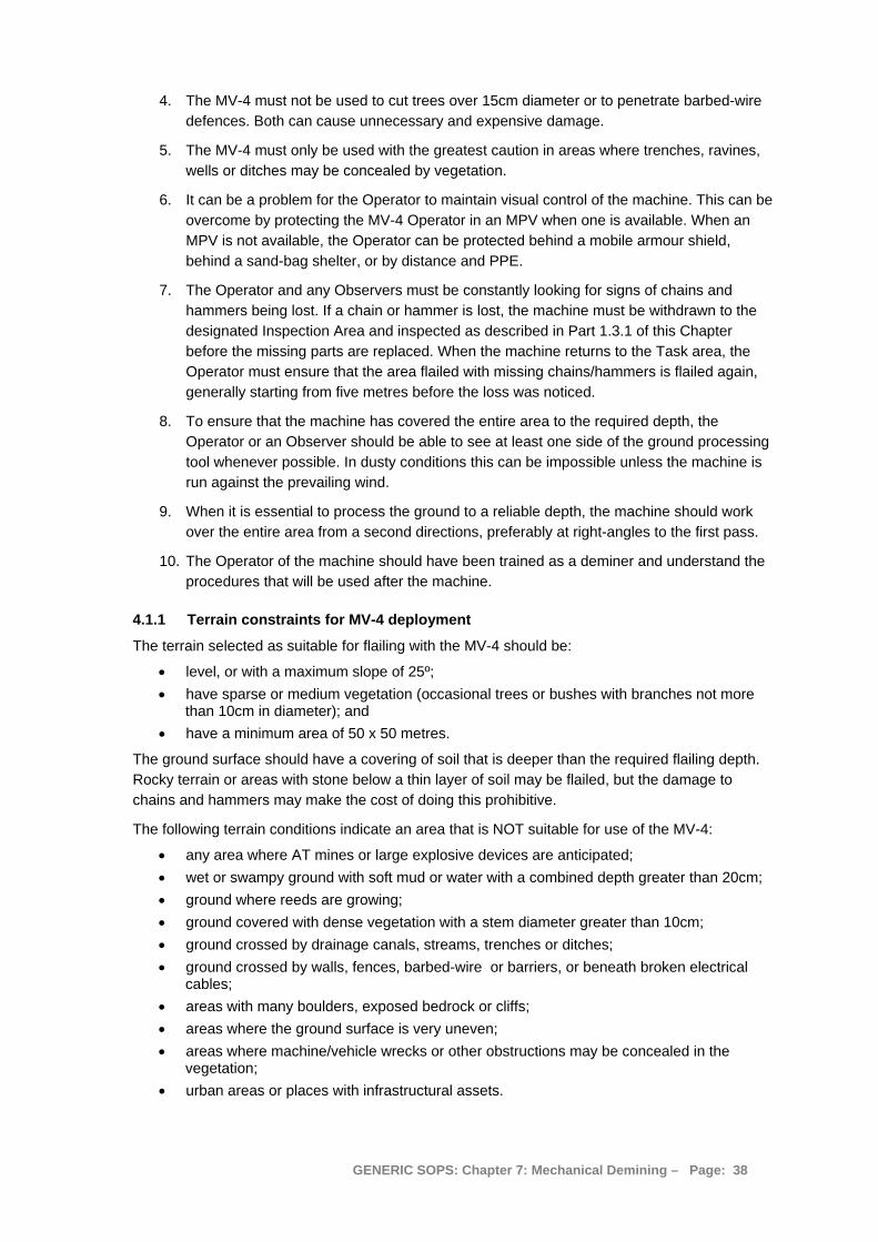
4. The MV-4 must not be used to cut trees over 15cm diameter or to penetrate barbed-wire defences. Both can cause unnecessary and expensive damage.
5. The MV-4 must only be used with the greatest caution in areas where trenches, ravines, wells or ditches may be concealed by vegetation.
6. It can be a problem for the Operator to maintain visual control of the machine. This can be overcome by protecting the MV-4 Operator in an MPV when one is available. When an MPV is not available, the Operator can be protected behind a mobile armour shield, behind a sand-bag shelter, or by distance and PPE.
7. The Operator and any Observers must be constantly looking for signs of chains and hammers being lost. If a chain or hammer is lost, the machine must be withdrawn to the designated Inspection Area and inspected as described in Part 1.3.1 of this Chapter before the missing parts are replaced. When the machine returns to the Task area, the Operator must ensure that the area flailed with missing chains/hammers is flailed again, generally starting from five metres before the loss was noticed.
8. To ensure that the machine has covered the entire area to the required depth, the Operator or an Observer should be able to see at least one side of the ground processing tool whenever possible. In dusty conditions this can be impossible unless the machine is run against the prevailing wind.
9. When it is essential to process the ground to a reliable depth, the machine should work over the entire area from a second directions, preferably at right-angles to the first pass.
10. The Operator of the machine should have been trained as a deminer and understand the procedures that will be used after the machine.
4.1.1 Terrain constraints for MV-4 deployment
The terrain selected as suitable for flailing with the MV-4 should be:
• level, or with a maximum slope of 25º; • have sparse or medium vegetation (occasional trees or bushes with branches not more
than 10cm in diameter); and • have a minimum area of 50 x 50 metres.
The ground surface should have a covering of soil that is deeper than the required flailing depth. Rocky terrain or areas with stone below a thin layer of soil may be flailed, but the damage to chains and hammers may make the cost of doing this prohibitive.
The following terrain conditions indicate an area that is NOT suitable for use of the MV-4:
• any area where AT mines or large explosive devices are anticipated; • wet or swampy ground with soft mud or water with a combined depth greater than 20cm; • ground where reeds are growing; • ground covered with dense vegetation with a stem diameter greater than 10cm; • ground crossed by drainage canals, streams, trenches or ditches; • ground crossed by walls, fences, barbed-wire or barriers, or beneath broken electrical
cables; • areas with many boulders, exposed bedrock or cliffs; • areas where the ground surface is very uneven; • areas where machine/vehicle wrecks or other obstructions may be concealed in the
vegetation; • urban areas or places with infrastructural assets.
GENERIC SOPS: Chapter 7: Mechanical Demining – Page: 38
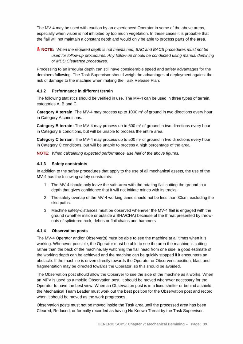
The MV-4 may be used with caution by an experienced Operator in some of the above areas, especially when vision is not inhibited by too much vegetation. In these cases it is probable that the flail will not maintain a constant depth and would only be able to process parts of the area.
NOTE: When the required depth is not maintained, BAC and BACS procedures must not be used for follow-up procedures. Any follow-up should be conducted using manual demining or MDD Clearance procedures.
Processing to an irregular depth can still have considerable speed and safety advantages for the deminers following. The Task Supervisor should weigh the advantages of deployment against the risk of damage to the machine when making the Task Release Plan.
4.1.2 Performance in different terrain
The following statistics should be verified in use. The MV-4 can be used in three types of terrain, categories A, B and C.
Category A terrain: The MV-4 may process up to 1000 m² of ground in two directions every hour in Category A conditions.
Category B terrain: The MV-4 may process up to 600 m² of ground in two directions every hour in Category B conditions, but will be unable to process the entire area.
Category C terrain: The MV-4 may process up to 500 m² of ground in two directions every hour in Category C conditions, but will be unable to process a high percentage of the area.
NOTE: When calculating expected performance, use half of the above figures.
4.1.3 Safety constraints
In addition to the safety procedures that apply to the use of all mechanical assets, the use of the MV-4 has the following safety constraints:
1. The MV-4 should only leave the safe-area with the rotating flail cutting the ground to a depth that gives confidence that it will not initiate mines with its tracks.
2. The safety overlap of the MV-4 working lanes should not be less than 30cm, excluding the skid paths.
3. Machine safety-distances must be observed whenever the MV-4 flail is engaged with the ground (whether inside or outside a SHA/CHA) because of the threat presented by throw-outs of splintered rock, debris or flail chains and hammers.
4.1.4 Observation posts
The MV-4 Operator and/or Observer(s) must be able to see the machine at all times when it is working. Whenever possible, the Operator must be able to see the area the machine is cutting rather than the back of the machine. By watching the flail head from one side, a good estimate of the working depth can be achieved and the machine can be quickly stopped if it encounters an obstacle. If the machine is driven directly towards the Operator or Observer’s position, blast and fragmentation may be directed towards the Operator, so this should be avoided.
The Observation post should allow the Observer to see the side of the machine as it works. When an MPV is used as a mobile Observation post, it should be moved whenever necessary for the Operator to have the best view. When an Observation post is in a fixed shelter or behind a shield, the Mechanical Team Leader must work out the best position for the Observation post and record when it should be moved as the work progresses.
Observation posts must not be moved inside the Task area until the processed area has been Cleared, Reduced, or formally recorded as having No Known Threat by the Task Supervisor.
GENERIC SOPS: Chapter 7: Mechanical Demining – Page: 39
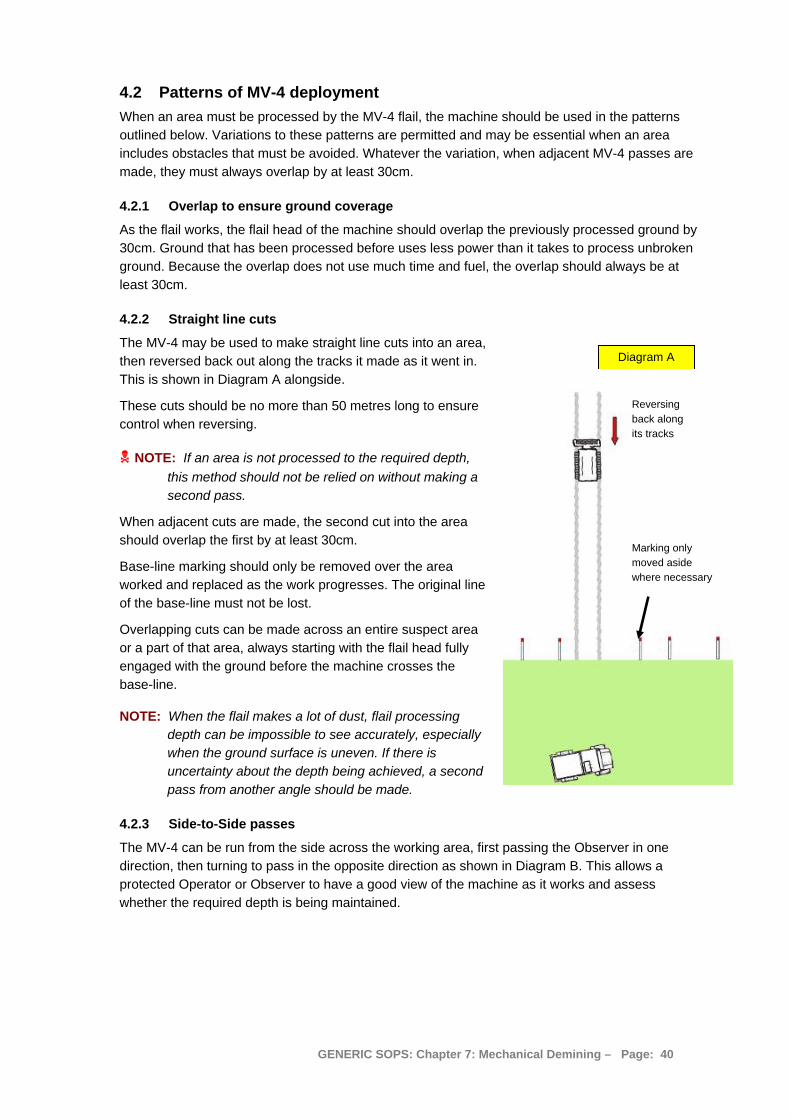
4.2 Patterns of MV-4 deployment When an area must be processed by the MV-4 flail, the machine should be used in the patterns outlined below. Variations to these patterns are permitted and may be essential when an area includes obstacles that must be avoided. Whatever the variation, when adjacent MV-4 passes are made, they must always overlap by at least 30cm.
4.2.1 Overlap to ensure ground coverage
As the flail works, the flail head of the machine should overlap the previously processed ground by 30cm. Ground that has been processed before uses less power than it takes to process unbroken ground. Because the overlap does not use much time and fuel, the overlap should always be at least 30cm.
4.2.2 Straight line cuts
The MV-4 may be used to make straight line cuts into an area, then reversed back out along the tracks it made as it went in. This is shown in Diagram A alongside.
Diagram A
These cuts should be no more than 50 metres long to ensure control when reversing.
Reversing back along its tracks
NOTE: If an area is not processed to the required depth, this method should not be relied on without making a second pass.
When adjacent cuts are made, the second cut into the area should overlap the first by at least 30cm. Marking only
moved aside where necessary
Base-line marking should only be removed over the area worked and replaced as the work progresses. The original line of the base-line must not be lost.
Overlapping cuts can be made across an entire suspect area or a part of that area, always starting with the flail head fully engaged with the ground before the machine crosses the base-line.
NOTE: When the flail makes a lot of dust, flail processing depth can be impossible to see accurately, especially when the ground surface is uneven. If there is uncertainty about the depth being achieved, a second pass from another angle should be made.
4.2.3 Side-to-Side passes
The MV-4 can be run from the side across the working area, first passing the Observer in one direction, then turning to pass in the opposite direction as shown in Diagram B. This allows a protected Operator or Observer to have a good view of the machine as it works and assess whether the required depth is being maintained.
GENERIC SOPS: Chapter 7: Mechanical Demining – Page: 40
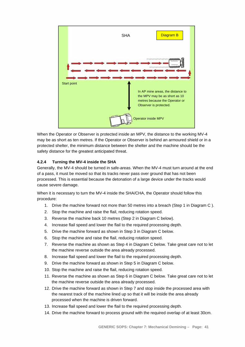
SHA
Start point
Operator inside MPV
Diagram B
In AP mine areas, the distance to the MPV may be as short as 10 metres because the Operator or Observer is protected.
When the Operator or Observer is protected inside an MPV, the distance to the working MV-4 may be as short as ten metres. If the Operator or Observer is behind an armoured shield or in a protected shelter, the minimum distance between the shelter and the machine should be the safety distance for the greatest anticipated threat.
4.2.4 Turning the MV-4 inside the SHA Generally, the MV-4 should be turned in safe-areas. When the MV-4 must turn around at the end of a pass, it must be moved so that its tracks never pass over ground that has not been processed. This is essential because the detonation of a large device under the tracks would cause severe damage.
When it is necessary to turn the MV-4 inside the SHA/CHA, the Operator should follow this procedure:
1. Drive the machine forward not more than 50 metres into a breach (Step 1 in Diagram C ). 2. Stop the machine and raise the flail, reducing rotation speed. 3. Reverse the machine back 10 metres (Step 2 in Diagram C below). 4. Increase flail speed and lower the flail to the required processing depth. 5. Drive the machine forward as shown in Step 3 in Diagram C below. 6. Stop the machine and raise the flail, reducing rotation speed. 7. Reverse the machine as shown as Step 4 in Diagram C below. Take great care not to let
the machine reverse outside the area already processed. 8. Increase flail speed and lower the flail to the required processing depth. 9. Drive the machine forward as shown in Step 5 in Diagram C below. 10. Stop the machine and raise the flail, reducing rotation speed. 11. Reverse the machine as shown as Step 6 in Diagram C below. Take great care not to let
the machine reverse outside the area already processed. 12. Drive the machine forward as shown in Step 7 and stop inside the processed area with
the nearest track of the machine lined up so that it will be inside the area already processed when the machine is driven forward.
13. Increase flail speed and lower the flail to the required processing depth. 14. Drive the machine forward to process ground with the required overlap of at least 30cm.
GENERIC SOPS: Chapter 7: Mechanical Demining – Page: 41
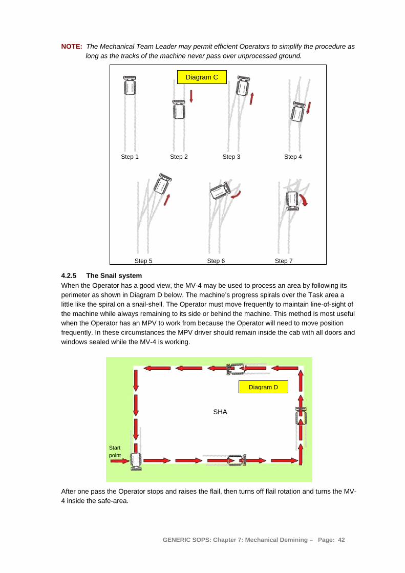
NOTE: The Mechanical Team Leader may permit efficient Operators to simplify the procedure as long as the tracks of the machine never pass over unprocessed ground.
Step 1 Step 2 Step 3 Step 4
Step 5 Step 6 Step 7
Diagram C
4.2.5 The Snail system When the Operator has a good view, the MV-4 may be used to process an area by following its perimeter as shown in Diagram D below. The machine’s progress spirals over the Task area a little like the spiral on a snail-shell. The Operator must move frequently to maintain line-of-sight of the machine while always remaining to its side or behind the machine. This method is most useful when the Operator has an MPV to work from because the Operator will need to move position frequently. In these circumstances the MPV driver should remain inside the cab with all doors and windows sealed while the MV-4 is working.
Diagram D
SHA
Start point
After one pass the Operator stops and raises the flail, then turns off flail rotation and turns the MV-4 inside the safe-area.
GENERIC SOPS: Chapter 7: Mechanical Demining – Page: 42
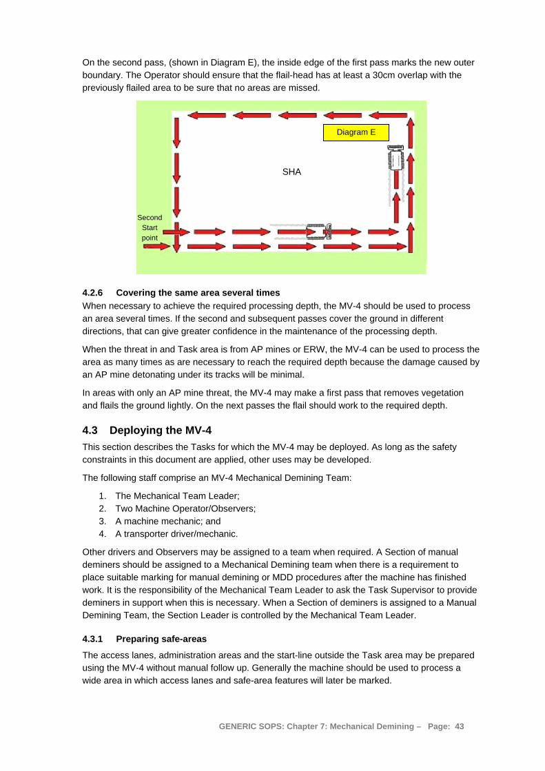
On the second pass, (shown in Diagram E), the inside edge of the first pass marks the new outer boundary. The Operator should ensure that the flail-head has at least a 30cm overlap with the previously flailed area to be sure that no areas are missed.
Diagram E
Second Start point
SHA
4.2.6 Covering the same area several times When necessary to achieve the required processing depth, the MV-4 should be used to process an area several times. If the second and subsequent passes cover the ground in different directions, that can give greater confidence in the maintenance of the processing depth.
When the threat in and Task area is from AP mines or ERW, the MV-4 can be used to process the area as many times as are necessary to reach the required depth because the damage caused by an AP mine detonating under its tracks will be minimal.
In areas with only an AP mine threat, the MV-4 may make a first pass that removes vegetation and flails the ground lightly. On the next passes the flail should work to the required depth.
4.3 Deploying the MV-4 This section describes the Tasks for which the MV-4 may be deployed. As long as the safety constraints in this document are applied, other uses may be developed.
The following staff comprise an MV-4 Mechanical Demining Team:
1. The Mechanical Team Leader; 2. Two Machine Operator/Observers; 3. A machine mechanic; and 4. A transporter driver/mechanic.
Other drivers and Observers may be assigned to a team when required. A Section of manual deminers should be assigned to a Mechanical Demining team when there is a requirement to place suitable marking for manual demining or MDD procedures after the machine has finished work. It is the responsibility of the Mechanical Team Leader to ask the Task Supervisor to provide deminers in support when this is necessary. When a Section of deminers is assigned to a Manual Demining Team, the Section Leader is controlled by the Mechanical Team Leader.
4.3.1 Preparing safe-areas
The access lanes, administration areas and the start-line outside the Task area may be prepared using the MV-4 without manual follow up. Generally the machine should be used to process a wide area in which access lanes and safe-area features will later be marked.
GENERIC SOPS: Chapter 7: Mechanical Demining – Page: 43
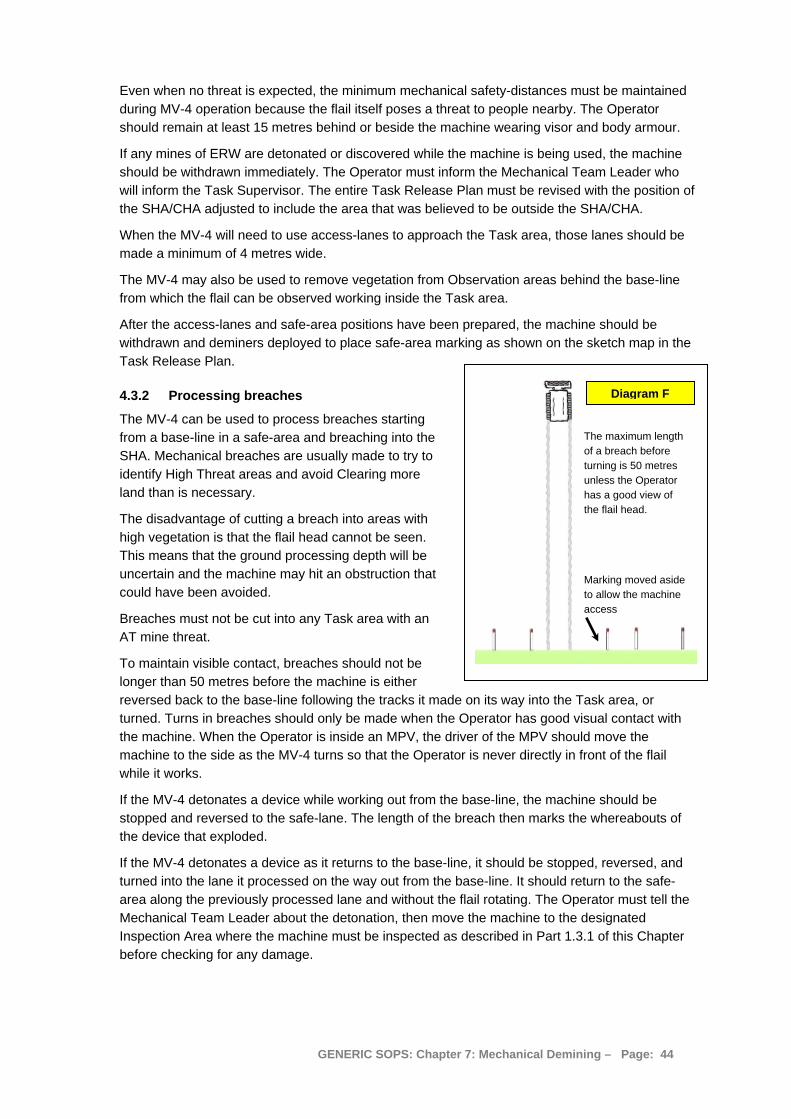
Even when no threat is expected, the minimum mechanical safety-distances must be maintained during MV-4 operation because the flail itself poses a threat to people nearby. The Operator should remain at least 15 metres behind or beside the machine wearing visor and body armour.
If any mines of ERW are detonated or discovered while the machine is being used, the machine should be withdrawn immediately. The Operator must inform the Mechanical Team Leader who will inform the Task Supervisor. The entire Task Release Plan must be revised with the position of the SHA/CHA adjusted to include the area that was believed to be outside the SHA/CHA.
When the MV-4 will need to use access-lanes to approach the Task area, those lanes should be made a minimum of 4 metres wide.
The MV-4 may also be used to remove vegetation from Observation areas behind the base-line from which the flail can be observed working inside the Task area.
After the access-lanes and safe-area positions have been prepared, the machine should be withdrawn and deminers deployed to place safe-area marking as shown on the sketch map in the Task Release Plan.
4.3.2 Processing breaches
The MV-4 can be used to process breaches starting from a base-line in a safe-area and breaching into the SHA. Mechanical breaches are usually made to try to identify High Threat areas and avoid Clearing more land than is necessary.
The disadvantage of cutting a breach into areas with high vegetation is that the flail head cannot be seen. This means that the ground processing depth will be uncertain and the machine may hit an obstruction that could have been avoided.
Breaches must not be cut into any Task area with an AT mine threat.
To maintain visible contact, breaches should not be longer than 50 metres before the machine is either reversed back to the base-line following the tracks it made on its way into the Task area, or turned. Turns in breaches should only be made when the Operator has good visual contact with the machine. When the Operator is inside an MPV, the driver of the MPV should move the machine to the side as the MV-4 turns so that the Operator is never directly in front of the flail while it works.
Marking moved aside to allow the machine access
Diagram F
The maximum length of a breach before turning is 50 metres unless the Operator has a good view of the flail head.
If the MV-4 detonates a device while working out from the base-line, the machine should be stopped and reversed to the safe-lane. The length of the breach then marks the whereabouts of the device that exploded.
If the MV-4 detonates a device as it returns to the base-line, it should be stopped, reversed, and turned into the lane it processed on the way out from the base-line. It should return to the safe-area along the previously processed lane and without the flail rotating. The Operator must tell the Mechanical Team Leader about the detonation, then move the machine to the designated Inspection Area where the machine must be inspected as described in Part 1.3.1 of this Chapter before checking for any damage.
GENERIC SOPS: Chapter 7: Mechanical Demining – Page: 44

4.3.3 Using the MV-4 to process road verges
Road verges should be processed to 8.5 metres from the centre of the road unless another distance is specified in the Task Folder.
NOTE: If there is a threat of AT mines on the verge, the MV-4 must not be used.
The road itself should first be processed in a manner that allows it to be considered Cleared or as presenting No Known Threat.
When the road is safe to use, the MV-4 is deployed in the following manner:
1. The verge should be processed in 50 metre lengths. Place Section-picket markers 50 metres apart on the verge to indicate the start and finish points for the machine.
2. Inspect the section of verge to see whether any obstructions can be seen. If obstructions can be seen, place red painted stones on the road alongside the obstructions to remind the Operator of their position.
3. Position the Observer or Operator so that they can see the flail head from the side.
4. Position the MV-4 so that it can move off the road at an angle and begin processing the ground before it passes the Start of Section-picket. This provides an overlap with the area already processed or the area believed safe.
5. Bring the flail head up to speed and lower it to the required processing depth.
6. Drive the machine parallel to the road without disturbing the road surface unnecessarily.
If the flail does not cut to the required depth, stop the machine, lift the flail-head, reverse the machine by five metres, lower the flail head and process the ground again.
7. When the machine passes the end of Section-marker, stop the machine, raise the flail head and stop the rotation.
8. Reverse the machine to its start point or onto the road, keeping its tracks always on ground already processed.
9. Manoeuvre the machine so that it is parallel to the first cut and the flail head overlaps that cut by at least 30cm.
10. Bring the flail rotation up to speed and lower the flail head to process the ground to the required depth.
11. Drive the machine forward ensuring the area processed overlaps the last pass by at least 30cm all along its length.
12. Repeat steps 5 to nine until the machine is processing ground more than 10 metres from the road.
There are frequently obstructions on road verges. The Operator/Observer must keep a close watch for ditches, rocks, vehicle wrecks or other obstructions. When an obstruction is seen, the machine may process up to it without allowing the flail-chains to touch it. The flail-head should be raised and the machine reversed so that it can manoeuvre around the obstruction. When manoeuvring around the obstruction, the machine should be processing the ground it drives over.
4.3.4 Using the MV-4 for cutting vegetation
Cutting vegetation does not require the flail to process the ground to any consistent depth.
The MV-4 can be used to remove vegetation in areas where AP mines are anticipated and manual demining or MDD Teams will later be used in the area. Vegetation removal without ground processing is necessary if the Task release Plan involves using BAC or BACS in the area.
When a wide-area is to be prepared by the MV-4 flail, this should be achieved by using the machine in the patterns approved above.
GENERIC SOPS: Chapter 7: Mechanical Demining – Page: 45
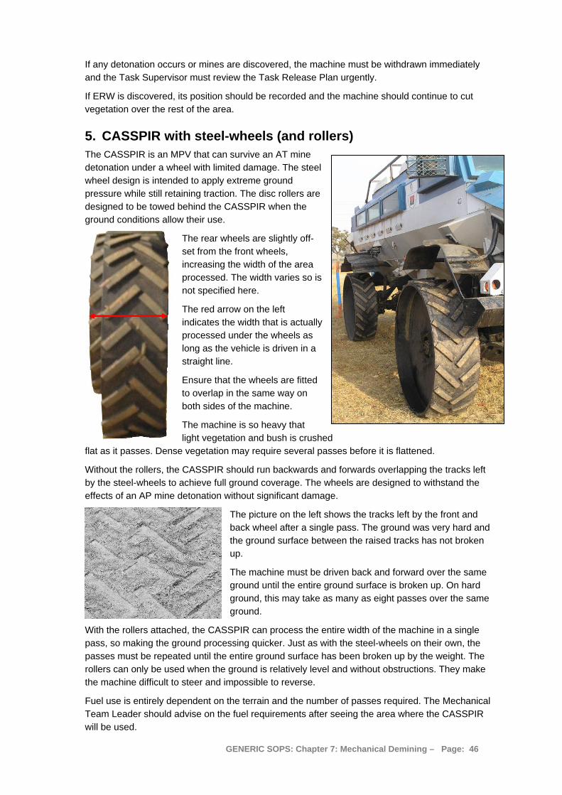
If any detonation occurs or mines are discovered, the machine must be withdrawn immediately and the Task Supervisor must review the Task Release Plan urgently.
If ERW is discovered, its position should be recorded and the machine should continue to cut vegetation over the rest of the area.
5. CASSPIR with steel-wheels (and rollers) The CASSPIR is an MPV that can survive an AT mine detonation under a wheel with limited damage. The steel wheel design is intended to apply extreme ground pressure while still retaining traction. The disc rollers are designed to be towed behind the CASSPIR when the ground conditions allow their use.
The rear wheels are slightly off-set from the front wheels, increasing the width of the area processed. The width varies so is not specified here.
The red arrow on the left indicates the width that is actually processed under the wheels as long as the vehicle is driven in a straight line.
Ensure that the wheels are fitted to overlap in the same way on both sides of the machine.
The machine is so heavy that light vegetation and bush is crushed
flat as it passes. Dense vegetation may require several passes before it is flattened.
Without the rollers, the CASSPIR should run backwards and forwards overlapping the tracks left by the steel-wheels to achieve full ground coverage. The wheels are designed to withstand the effects of an AP mine detonation without significant damage.
The picture on the left shows the tracks left by the front and back wheel after a single pass. The ground was very hard and the ground surface between the raised tracks has not broken up.
The machine must be driven back and forward over the same ground until the entire ground surface is broken up. On hard ground, this may take as many as eight passes over the same ground.
With the rollers attached, the CASSPIR can process the entire width of the machine in a single pass, so making the ground processing quicker. Just as with the steel-wheels on their own, the passes must be repeated until the entire ground surface has been broken up by the weight. The rollers can only be used when the ground is relatively level and without obstructions. They make the machine difficult to steer and impossible to reverse.
Fuel use is entirely dependent on the terrain and the number of passes required. The Mechanical Team Leader should advise on the fuel requirements after seeing the area where the CASSPIR will be used.
GENERIC SOPS: Chapter 7: Mechanical Demining – Page: 46
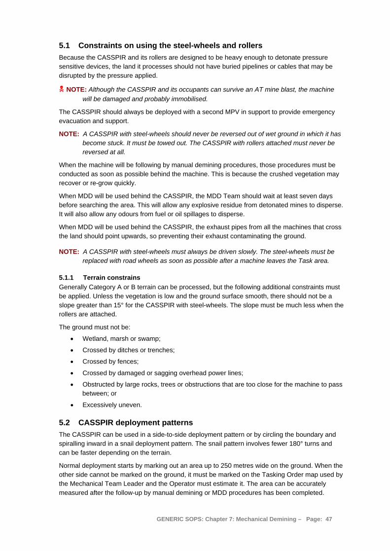
5.1 Constraints on using the steel-wheels and rollers Because the CASSPIR and its rollers are designed to be heavy enough to detonate pressure sensitive devices, the land it processes should not have buried pipelines or cables that may be disrupted by the pressure applied.
NOTE: Although the CASSPIR and its occupants can survive an AT mine blast, the machine will be damaged and probably immobilised.
The CASSPIR should always be deployed with a second MPV in support to provide emergency evacuation and support.
NOTE: A CASSPIR with steel-wheels should never be reversed out of wet ground in which it has become stuck. It must be towed out. The CASSPIR with rollers attached must never be reversed at all.
When the machine will be following by manual demining procedures, those procedures must be conducted as soon as possible behind the machine. This is because the crushed vegetation may recover or re-grow quickly.
When MDD will be used behind the CASSPIR, the MDD Team should wait at least seven days before searching the area. This will allow any explosive residue from detonated mines to disperse. It will also allow any odours from fuel or oil spillages to disperse.
When MDD will be used behind the CASSPIR, the exhaust pipes from all the machines that cross the land should point upwards, so preventing their exhaust contaminating the ground.
NOTE: A CASSPIR with steel-wheels must always be driven slowly. The steel-wheels must be replaced with road wheels as soon as possible after a machine leaves the Task area.
5.1.1 Terrain constrains Generally Category A or B terrain can be processed, but the following additional constraints must be applied. Unless the vegetation is low and the ground surface smooth, there should not be a slope greater than 15° for the CASSPIR with steel-wheels. The slope must be much less when the rollers are attached.
The ground must not be:
• Wetland, marsh or swamp;
• Crossed by ditches or trenches;
• Crossed by fences;
• Crossed by damaged or sagging overhead power lines;
• Obstructed by large rocks, trees or obstructions that are too close for the machine to pass between; or
• Excessively uneven.
5.2 CASSPIR deployment patterns The CASSPIR can be used in a side-to-side deployment pattern or by circling the boundary and spiralling inward in a snail deployment pattern. The snail pattern involves fewer 180° turns and can be faster depending on the terrain.
Normal deployment starts by marking out an area up to 250 metres wide on the ground. When the other side cannot be marked on the ground, it must be marked on the Tasking Order map used by the Mechanical Team Leader and the Operator must estimate it. The area can be accurately measured after the follow-up by manual demining or MDD procedures has been completed.
GENERIC SOPS: Chapter 7: Mechanical Demining – Page: 47
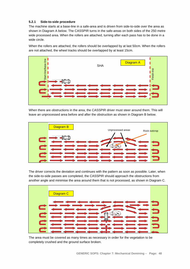
5.2.1 Side-to-side procedure The machine starts at a base-line in a safe-area and is driven from side-to-side over the area as shown in Diagram A below. The CASSPIR turns in the safe-areas on both sides of the 250 metre wide processed area. When the rollers are attached, turning after each pass has to be done in a wide circle.
When the rollers are attached, the rollers should be overlapped by at last 50cm. When the rollers are not attached, the wheel tracks should be overlapped by at least 15cm.
Sta
rt-lin
e/ba
se-li
ne
Fini
sh-li
ne SHA
Diagram A
When there are obstructions in the area, the CASSPIR driver must steer around them. This will leave an unprocessed area before and after the obstruction as shown in Diagram B below.
Unprocessed areas Diagram B
Rock outcrop
The driver corrects the deviation and continues with the pattern as soon as possible. Later, when the side-to-side passes are completed, the CASSPIR should approach the obstructions from another angle and minimise the area around them that is not processed, as shown in Diagram C.
Diagram C
The area must be covered as many times as necessary in order for the vegetation to be completely crushed and the ground surface broken.
GENERIC SOPS: Chapter 7: Mechanical Demining – Page: 48

Areas that have not been processed must be marked on the Tasking map. They will generally be visible and obvious to those following up, so it is not necessary to record their GPS coordinates.
5.2.2 The Snail procedure
The snail system can be used with start and exit points, or with a single entry point and a spiral deployment pattern that does not exit on every circuit.
When the snail system is used with start and exit points, two adjacent sides of the area should be safe-areas so that the CASSPIR can turn as shown in Diagram D below.
Finish-line
Diagram D
SHA
Sta
rt-lin
e
The CASSPIR starts at a base-line in a safe-area and is driven around the perimeter of the area. The CASSPIR turns in the safe-area behind the finish-line and approaches the start-line again. When the rollers are attached, turning after each pass has to be done in a wide circle.
The most efficient way to use the CASSPIR with the steel rollers attached is in the snail-pattern, without making an exit on each cycle, as shown in Diagram E on the right.
Diagram E Diagram E
The Machine is driven in a large circle and each subsequent circle continues inside (and overlapping) the previous circle, so spiralling inward until the machine cannot turn tightly enough to complete the centre. Then the machine should be driven to the side and approach the final area from another angle. When this variation is used, only one safe-area start-line is needed.
Sta
rt-po
int
SHA
GENERIC SOPS: Chapter 7: Mechanical Demining – Page: 49
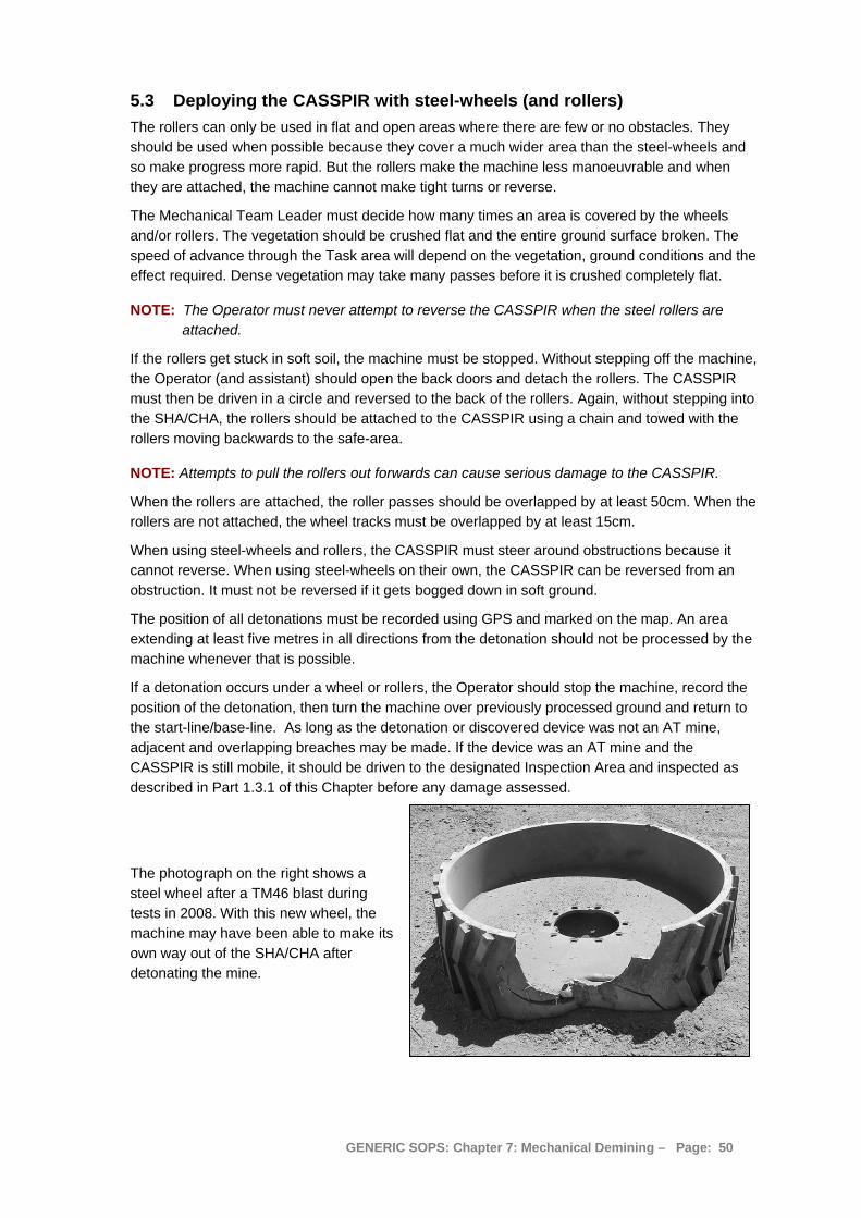
5.3 Deploying the CASSPIR with steel-wheels (and rollers) The rollers can only be used in flat and open areas where there are few or no obstacles. They should be used when possible because they cover a much wider area than the steel-wheels and so make progress more rapid. But the rollers make the machine less manoeuvrable and when they are attached, the machine cannot make tight turns or reverse.
The Mechanical Team Leader must decide how many times an area is covered by the wheels and/or rollers. The vegetation should be crushed flat and the entire ground surface broken. The speed of advance through the Task area will depend on the vegetation, ground conditions and the effect required. Dense vegetation may take many passes before it is crushed completely flat.
NOTE: The Operator must never attempt to reverse the CASSPIR when the steel rollers are attached.
If the rollers get stuck in soft soil, the machine must be stopped. Without stepping off the machine, the Operator (and assistant) should open the back doors and detach the rollers. The CASSPIR must then be driven in a circle and reversed to the back of the rollers. Again, without stepping into the SHA/CHA, the rollers should be attached to the CASSPIR using a chain and towed with the rollers moving backwards to the safe-area.
NOTE: Attempts to pull the rollers out forwards can cause serious damage to the CASSPIR.
When the rollers are attached, the roller passes should be overlapped by at least 50cm. When the rollers are not attached, the wheel tracks must be overlapped by at least 15cm.
When using steel-wheels and rollers, the CASSPIR must steer around obstructions because it cannot reverse. When using steel-wheels on their own, the CASSPIR can be reversed from an obstruction. It must not be reversed if it gets bogged down in soft ground.
The position of all detonations must be recorded using GPS and marked on the map. An area extending at least five metres in all directions from the detonation should not be processed by the machine whenever that is possible.
If a detonation occurs under a wheel or rollers, the Operator should stop the machine, record the position of the detonation, then turn the machine over previously processed ground and return to the start-line/base-line. As long as the detonation or discovered device was not an AT mine, adjacent and overlapping breaches may be made. If the device was an AT mine and the CASSPIR is still mobile, it should be driven to the designated Inspection Area and inspected as described in Part 1.3.1 of this Chapter before any damage assessed.
The photograph on the right shows a steel wheel after a TM46 blast during tests in 2008. With this new wheel, the machine may have been able to make its own way out of the SHA/CHA after detonating the mine.
GENERIC SOPS: Chapter 7: Mechanical Demining – Page: 50
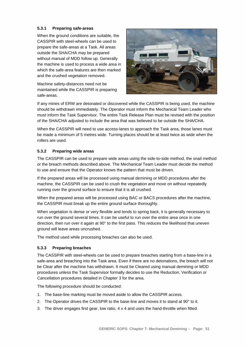
5.3.1 Preparing safe-areas
When the ground conditions are suitable, the CASSPIR with steel-wheels can be used to prepare the safe-areas at a Task. All areas outside the SHA/CHA may be prepared without manual of MDD follow up. Generally the machine is used to process a wide area in which the safe-area features are then marked and the crushed vegetation removed.
Machine safety-distances need not be maintained while the CASSPIR is preparing safe-areas.
If any mines of ERW are detonated or discovered while the CASSPIR is being used, the machine should be withdrawn immediately. The Operator must inform the Mechanical Team Leader who must inform the Task Supervisor. The entire Task Release Plan must be revised with the position of the SHA/CHA adjusted to include the area that was believed to be outside the SHA/CHA.
When the CASSPIR will need to use access-lanes to approach the Task area, those lanes must be made a minimum of 5 metres wide. Turning places should be at least twice as wide when the rollers are used.
5.3.2 Preparing wide areas
The CASSPIR can be used to prepare wide areas using the side-to-side method, the snail method or the breach methods described above. The Mechanical Team Leader must decide the method to use and ensure that the Operator knows the pattern that must be driven.
If the prepared areas will be processed using manual demining or MDD procedures after the machine, the CASSPIR can be used to crush the vegetation and move on without repeatedly running over the ground surface to ensure that it is all crushed.
When the prepared areas will be processed using BAC or BACS procedures after the machine, the CASSPIR must break up the entire ground surface thoroughly.
When vegetation is dense or very flexible and tends to spring back, it is generally necessary to run over the ground several times. It can be useful to run over the entire area once in one direction, then run over it again at 90° to the first pass. This reduces the likelihood that uneven ground will leave areas uncrushed.
The method used while processing breaches can also be used.
5.3.3 Preparing breaches
The CASSPIR with steel-wheels can be used to prepare breaches starting from a base-line in a safe-area and breaching into the Task area. Even if there are no detonations, the breach will not be Clear after the machine has withdrawn. It must be Cleared using manual demining or MDD procedures unless the Task Supervisor formally decides to use the Reduction, Verification or Cancellation procedures detailed in Chapter 3 for the area.
The following procedure should be conducted:
1. The base-line marking must be moved aside to allow the CASSPIR access.
2. The Operator drives the CASSPIR to the base-line and moves it to stand at 90° to it.
3. The driver engages first gear, low ratio, 4 x 4 and uses the hand-throttle when fitted.
GENERIC SOPS: Chapter 7: Mechanical Demining – Page: 51
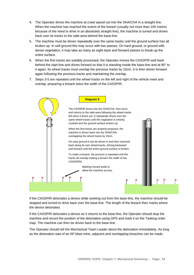
4. The Operator drives the machine at crawl speed out into the SHA/CHA in a straight line. When the machine has reached the extent of the breach (usually not more than 100 metres because of the need to drive in an absolutely straight line), the machine is turned and driven back over its tracks to the safe-area behind the base-line.
5. The machine must be driven repeatedly over the same tracks until the ground surface has all broken up. In soft ground this may occur with two passes. On hard ground, or ground with dense vegetation, it may take as many as eight back and forward passes to break up the entire surface.
6. When the first tracks are suitably processed, the Operator moves the CASSPIR well back behind the start-line and drives forward so that it is standing inside the base-line and at 90° to it again. Its wheel tracks must overlap the previous tracks by 15cm. It is then driven forward again following the previous tracks and maintaining the overlap.
7. Steps 3-5 are repeated until the wheel tracks on the left and right of the vehicle meet and overlap, preparing a breach twice the width of the CASSPIR.
Marking moved aside to allow the machine access.
Diagram E
The CASSPIR drives into the SHA/CHA, then turns and returns to the safe-area following the wheel-tracks left when it drove out. It repeatedly drives over the same wheel-tracks until the vegetation is entirely crushed and the ground surface broken up.
When the first tracks are properly prepared, the machine is driven back into the SHA/CHA, overlapping the wheel tracks by 15cm.
On easy ground it can be driven in and then reversed back along its own wheel-tracks, driving backward and forward until the entire ground surface is broken.
To make a breach, the process is repeated until the tracks all overlap making a breach the width of two CASSPIRS.
If the CASSPIR detonates a device while working out from the base-line, the machine should be stopped and turned to drive back over the base-line. The length of the breach then marks where the device detonated.
If the CASSPIR detonates a device as it returns to the base-line, the Operator should stop the machine and record the position of the detonation using GPS and mark it on the Tasking order map. The machine can then be driven back to the base-line.
The Operator should tell the Mechanical Team Leader about the detonation immediately. As long as the detonation was of an AP blast mine, adjacent and overlapping breaches can be made.
GENERIC SOPS: Chapter 7: Mechanical Demining – Page: 52
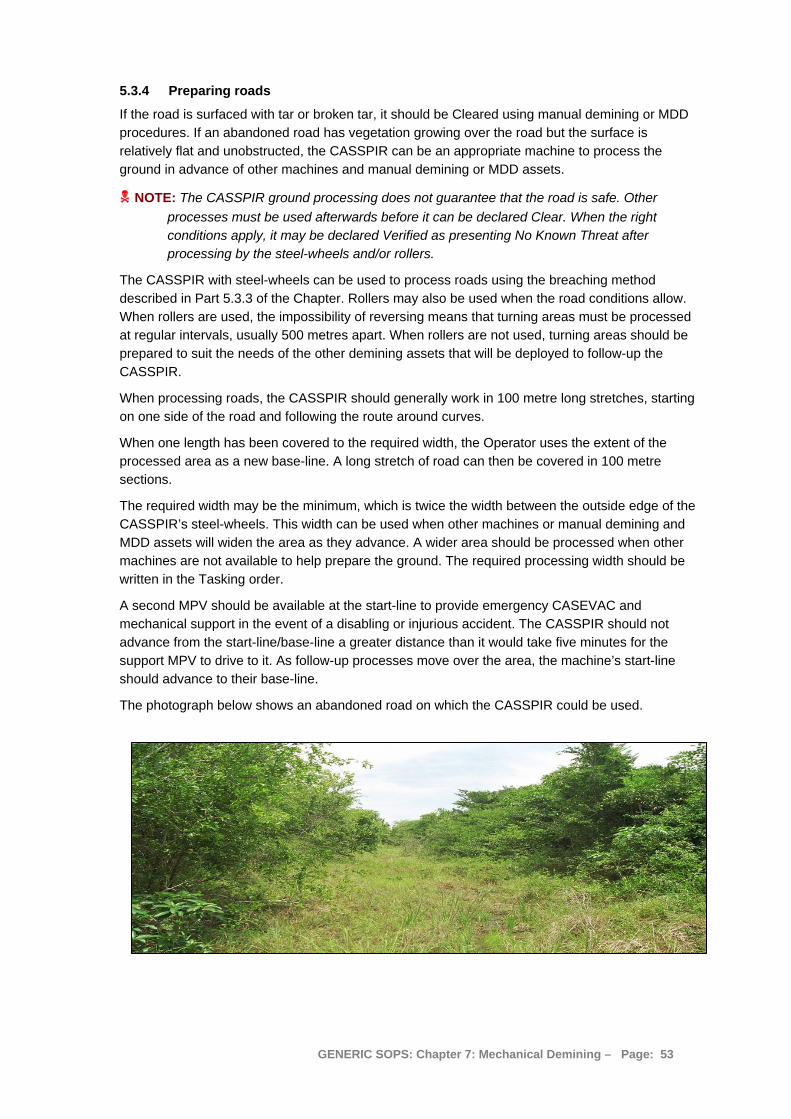
5.3.4 Preparing roads
If the road is surfaced with tar or broken tar, it should be Cleared using manual demining or MDD procedures. If an abandoned road has vegetation growing over the road but the surface is relatively flat and unobstructed, the CASSPIR can be an appropriate machine to process the ground in advance of other machines and manual demining or MDD assets.
NOTE: The CASSPIR ground processing does not guarantee that the road is safe. Other processes must be used afterwards before it can be declared Clear. When the right conditions apply, it may be declared Verified as presenting No Known Threat after processing by the steel-wheels and/or rollers.
The CASSPIR with steel-wheels can be used to process roads using the breaching method described in Part 5.3.3 of the Chapter. Rollers may also be used when the road conditions allow. When rollers are used, the impossibility of reversing means that turning areas must be processed at regular intervals, usually 500 metres apart. When rollers are not used, turning areas should be prepared to suit the needs of the other demining assets that will be deployed to follow-up the CASSPIR.
When processing roads, the CASSPIR should generally work in 100 metre long stretches, starting on one side of the road and following the route around curves.
When one length has been covered to the required width, the Operator uses the extent of the processed area as a new base-line. A long stretch of road can then be covered in 100 metre sections.
The required width may be the minimum, which is twice the width between the outside edge of the CASSPIR’s steel-wheels. This width can be used when other machines or manual demining and MDD assets will widen the area as they advance. A wider area should be processed when other machines are not available to help prepare the ground. The required processing width should be written in the Tasking order.
A second MPV should be available at the start-line to provide emergency CASEVAC and mechanical support in the event of a disabling or injurious accident. The CASSPIR should not advance from the start-line/base-line a greater distance than it would take five minutes for the support MPV to drive to it. As follow-up processes move over the area, the machine’s start-line should advance to their base-line.
The photograph below shows an abandoned road on which the CASSPIR could be used.
GENERIC SOPS: Chapter 7: Mechanical Demining – Page: 53
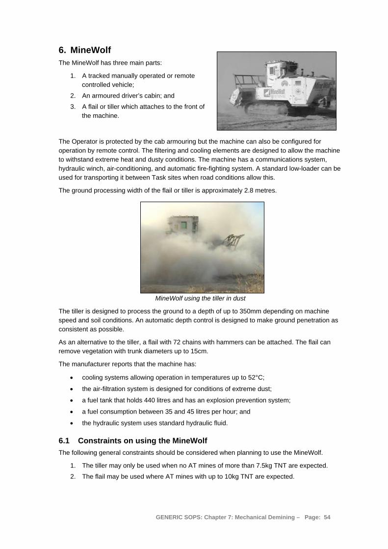
6. MineWolf The MineWolf has three main parts:
1. A tracked manually operated or remote controlled vehicle;
2. An armoured driver’s cabin; and
3. A flail or tiller which attaches to the front of the machine.
The Operator is protected by the cab armouring but the machine can also be configured for operation by remote control. The filtering and cooling elements are designed to allow the machine to withstand extreme heat and dusty conditions. The machine has a communications system, hydraulic winch, air-conditioning, and automatic fire-fighting system. A standard low-loader can be used for transporting it between Task sites when road conditions allow this.
The ground processing width of the flail or tiller is approximately 2.8 metres.
MineWolf using the tiller in dust
The tiller is designed to process the ground to a depth of up to 350mm depending on machine speed and soil conditions. An automatic depth control is designed to make ground penetration as consistent as possible.
As an alternative to the tiller, a flail with 72 chains with hammers can be attached. The flail can remove vegetation with trunk diameters up to 15cm.
The manufacturer reports that the machine has:
• cooling systems allowing operation in temperatures up to 52°C;
• the air-filtration system is designed for conditions of extreme dust;
• a fuel tank that holds 440 litres and has an explosion prevention system;
• a fuel consumption between 35 and 45 litres per hour; and
• the hydraulic system uses standard hydraulic fluid.
6.1 Constraints on using the MineWolf The following general constraints should be considered when planning to use the MineWolf.
1. The tiller may only be used when no AT mines of more than 7.5kg TNT are expected.
2. The flail may be used where AT mines with up to 10kg TNT are expected.
GENERIC SOPS: Chapter 7: Mechanical Demining – Page: 54
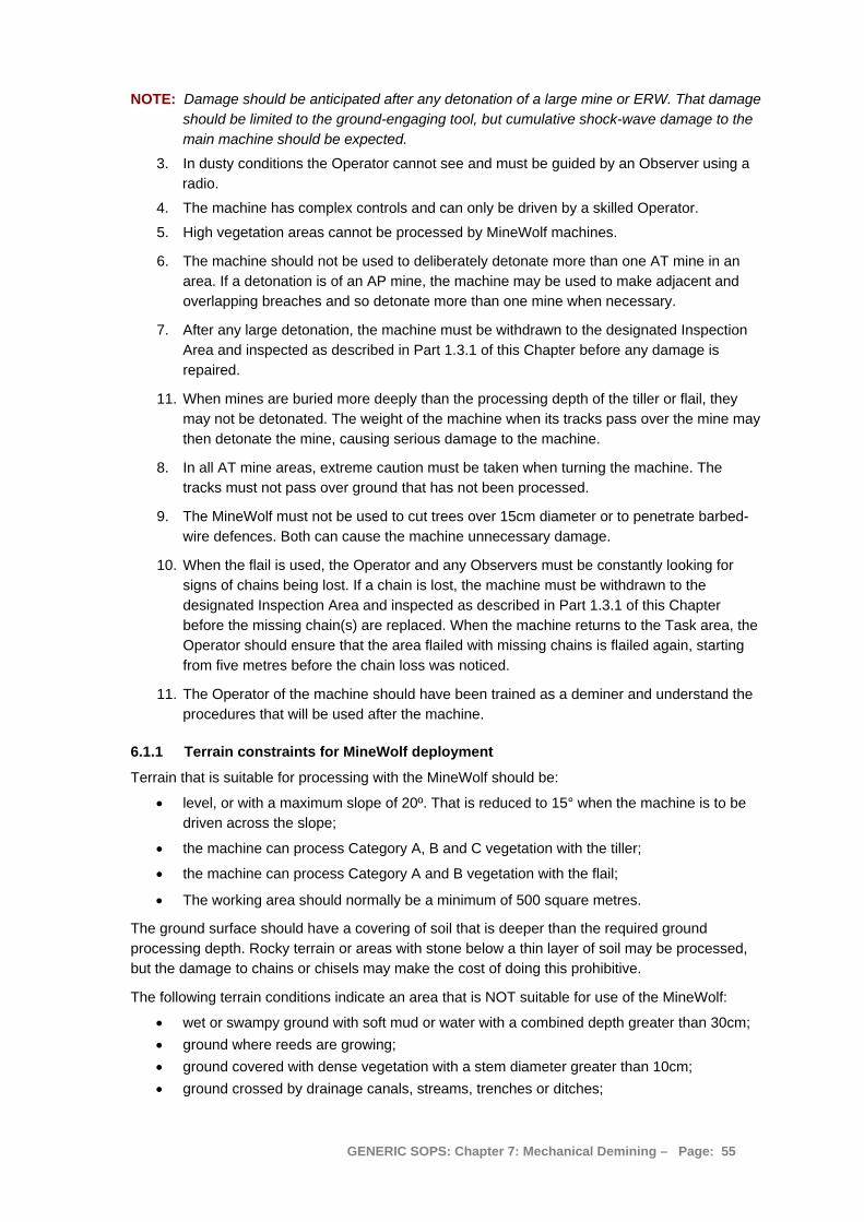
NOTE: Damage should be anticipated after any detonation of a large mine or ERW. That damage should be limited to the ground-engaging tool, but cumulative shock-wave damage to the main machine should be expected.
3. In dusty conditions the Operator cannot see and must be guided by an Observer using a radio.
4. The machine has complex controls and can only be driven by a skilled Operator.
5. High vegetation areas cannot be processed by MineWolf machines.
6. The machine should not be used to deliberately detonate more than one AT mine in an area. If a detonation is of an AP mine, the machine may be used to make adjacent and overlapping breaches and so detonate more than one mine when necessary.
7. After any large detonation, the machine must be withdrawn to the designated Inspection Area and inspected as described in Part 1.3.1 of this Chapter before any damage is repaired.
11. When mines are buried more deeply than the processing depth of the tiller or flail, they may not be detonated. The weight of the machine when its tracks pass over the mine may then detonate the mine, causing serious damage to the machine.
8. In all AT mine areas, extreme caution must be taken when turning the machine. The tracks must not pass over ground that has not been processed.
9. The MineWolf must not be used to cut trees over 15cm diameter or to penetrate barbed-wire defences. Both can cause the machine unnecessary damage.
10. When the flail is used, the Operator and any Observers must be constantly looking for signs of chains being lost. If a chain is lost, the machine must be withdrawn to the designated Inspection Area and inspected as described in Part 1.3.1 of this Chapter before the missing chain(s) are replaced. When the machine returns to the Task area, the Operator should ensure that the area flailed with missing chains is flailed again, starting from five metres before the chain loss was noticed.
11. The Operator of the machine should have been trained as a deminer and understand the procedures that will be used after the machine.
6.1.1 Terrain constraints for MineWolf deployment
Terrain that is suitable for processing with the MineWolf should be:
• level, or with a maximum slope of 20º. That is reduced to 15° when the machine is to be driven across the slope;
• the machine can process Category A, B and C vegetation with the tiller;
• the machine can process Category A and B vegetation with the flail;
• The working area should normally be a minimum of 500 square metres.
The ground surface should have a covering of soil that is deeper than the required ground processing depth. Rocky terrain or areas with stone below a thin layer of soil may be processed, but the damage to chains or chisels may make the cost of doing this prohibitive.
The following terrain conditions indicate an area that is NOT suitable for use of the MineWolf:
• wet or swampy ground with soft mud or water with a combined depth greater than 30cm; • ground where reeds are growing; • ground covered with dense vegetation with a stem diameter greater than 10cm; • ground crossed by drainage canals, streams, trenches or ditches;
GENERIC SOPS: Chapter 7: Mechanical Demining – Page: 55
• ground crossed by walls, fences, barbed-wire or barriers, or beneath broken electrical cables;
• areas with boulders, exposed bedrock or cliffs; • areas where the ground surface is very uneven; • areas where machine/vehicle wrecks or other obstructions may be concealed in the
vegetation; • deep and loose sand; • urban areas or places with infrastructural assets.
The MineWolf may be used with caution by an experienced Operator in some of the above areas although it is probable that the ground processing will not maintain a constant depth and the machine would only be able to process parts of the area.
NOTE: When the required depth is not maintained, BAC and BACS procedures must not be used as follow-up procedures. When the area must be declared Clear, it should be processed using manual demining or MDD Clearance procedures. When the right conditions apply, the area may be declared Verified as presenting No Known Threat after processing by the MineWolf.
Processing to an irregular depth can still have considerable speed and safety advantages for the deminers Clearing the area during follow up. The Task Supervisor should weigh the advantages of deployment against the costs and the risk of damage to the machine when making the Task Release Plan.
6.1.2 Performance in different terrain
The following statistics are derived from the manufacturer’s documentation and have not been verified in use. The MineWolf can be used in three types of terrain, categories A, B and C, subject to the terrain constraints listed in Part 6.1.1 and depending on whether the tiller or the flail is used.
The manufacturers claim a daily output of between 15,000m² - 30,000m² per day depending on the terrain. They do not record the length of a working day.
Category A terrain: The manufacturers claim that the MineWolf can process up to 30,000 m² of ground a day in Category A conditions.
Category B terrain: The manufacturers claim that the MineWolf can process between 15,000 m² and 30,000m² per day in Category B conditions.
Category C terrain: The manufacturers claim that the flail can effectively remove vegetation with trunk diameters up to 15cm in diameter, and process up to 15,000m² of ground a day in Category C conditions.
When calculating anticipated output, these figures should be halved and an eight hour day presumed. For example, in Category B conditions, presume 22,500m² divided by two, equals 11,250m² per day, or 1,400m² per hour, as the maximum likely to be achieved.
6.1.3 Safety constraints
In addition to the safety procedures that apply to the use of all mechanical assets, the use of the MineWolf has the following safety constraints:
1. The MineWolf should only leave the safe-area with the rotating tiller or flail operating at a depth that gives confidence that it will not initiate mines with its tracks.
2. The safety overlap of the MineWolf working lanes should never be less than 50cm, excluding the paths left by the skids on the sides of the tiller tool.
GENERIC SOPS: Chapter 7: Mechanical Demining – Page: 56
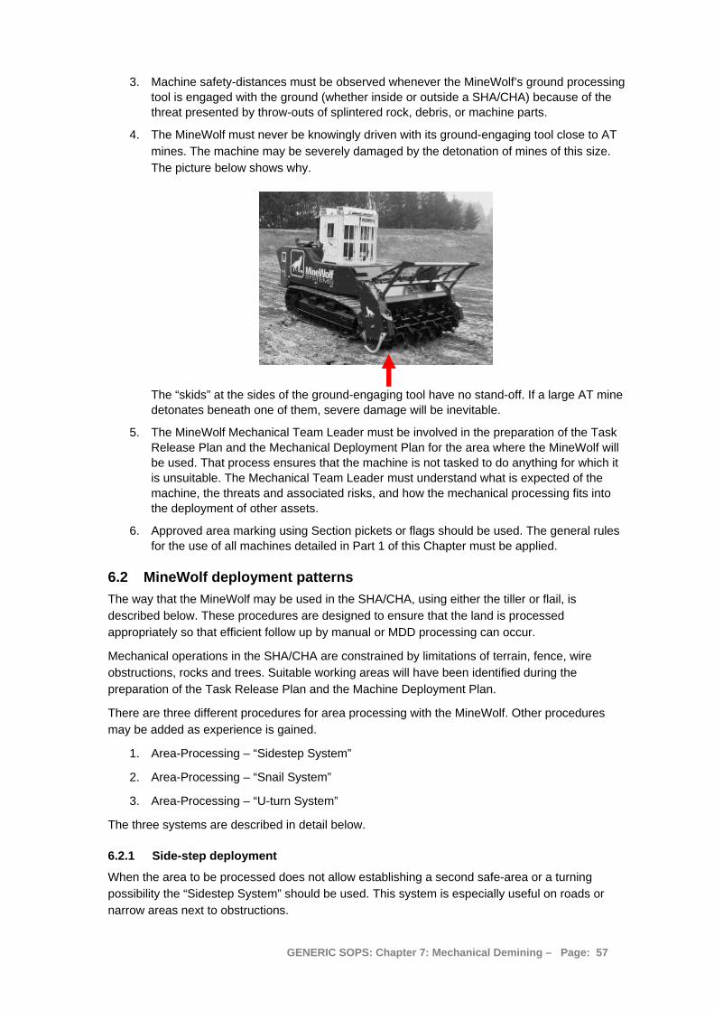
3. Machine safety-distances must be observed whenever the MineWolf’s ground processing tool is engaged with the ground (whether inside or outside a SHA/CHA) because of the threat presented by throw-outs of splintered rock, debris, or machine parts.
4. The MineWolf must never be knowingly driven with its ground-engaging tool close to AT mines. The machine may be severely damaged by the detonation of mines of this size. The picture below shows why.
The “skids” at the sides of the ground-engaging tool have no stand-off. If a large AT mine detonates beneath one of them, severe damage will be inevitable.
5. The MineWolf Mechanical Team Leader must be involved in the preparation of the Task Release Plan and the Mechanical Deployment Plan for the area where the MineWolf will be used. That process ensures that the machine is not tasked to do anything for which it is unsuitable. The Mechanical Team Leader must understand what is expected of the machine, the threats and associated risks, and how the mechanical processing fits into the deployment of other assets.
6. Approved area marking using Section pickets or flags should be used. The general rules for the use of all machines detailed in Part 1 of this Chapter must be applied.
6.2 MineWolf deployment patterns The way that the MineWolf may be used in the SHA/CHA, using either the tiller or flail, is described below. These procedures are designed to ensure that the land is processed appropriately so that efficient follow up by manual or MDD processing can occur.
Mechanical operations in the SHA/CHA are constrained by limitations of terrain, fence, wire obstructions, rocks and trees. Suitable working areas will have been identified during the preparation of the Task Release Plan and the Machine Deployment Plan.
There are three different procedures for area processing with the MineWolf. Other procedures may be added as experience is gained.
1. Area-Processing – “Sidestep System”
2. Area-Processing – “Snail System”
3. Area-Processing – “U-turn System”
The three systems are described in detail below.
6.2.1 Side-step deployment
When the area to be processed does not allow establishing a second safe-area or a turning possibility the “Sidestep System” should be used. This system is especially useful on roads or narrow areas next to obstructions.
GENERIC SOPS: Chapter 7: Mechanical Demining – Page: 57
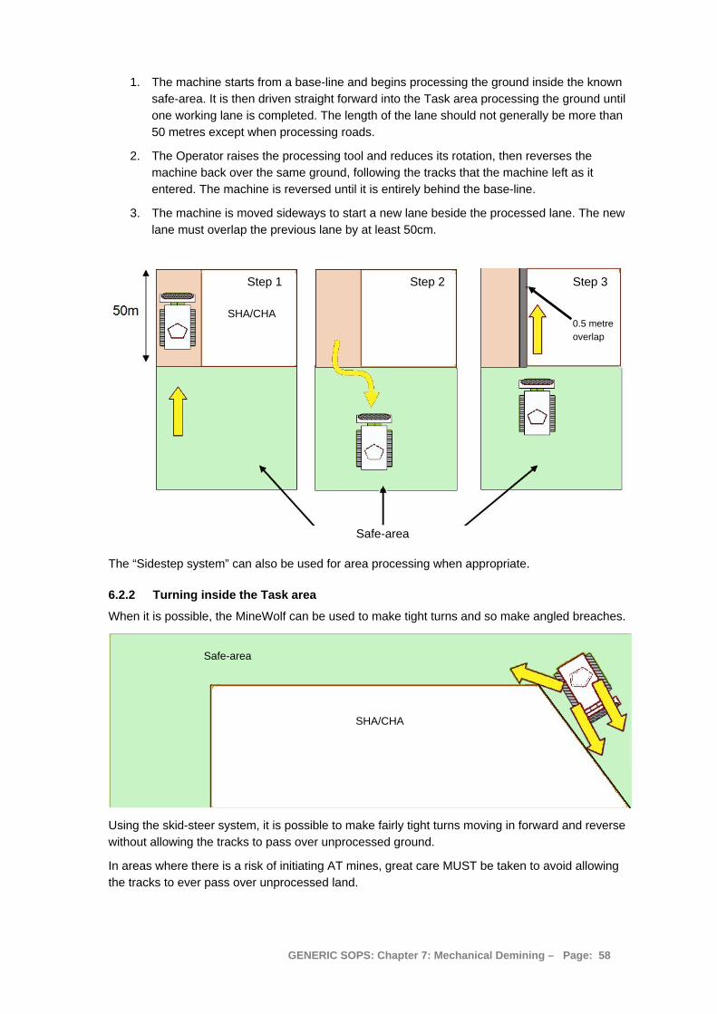
1. The machine starts from a base-line and begins processing the ground inside the known safe-area. It is then driven straight forward into the Task area processing the ground until one working lane is completed. The length of the lane should not generally be more than 50 metres except when processing roads.
2. The Operator raises the processing tool and reduces its rotation, then reverses the machine back over the same ground, following the tracks that the machine left as it entered. The machine is reversed until it is entirely behind the base-line.
3. The machine is moved sideways to start a new lane beside the processed lane. The new lane must overlap the previous lane by at least 50cm.
Step 1 Step 2 Step 3
Safe-area
SHA/CHA 0.5 metre overlap
The “Sidestep system” can also be used for area processing when appropriate.
6.2.2 Turning inside the Task area
When it is possible, the MineWolf can be used to make tight turns and so make angled breaches.
Safe-area
SHA/CHA
Using the skid-steer system, it is possible to make fairly tight turns moving in forward and reverse without allowing the tracks to pass over unprocessed ground.
In areas where there is a risk of initiating AT mines, great care MUST be taken to avoid allowing the tracks to ever pass over unprocessed land.
GENERIC SOPS: Chapter 7: Mechanical Demining – Page: 58
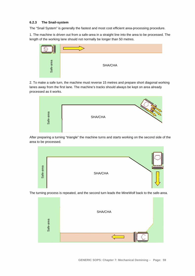
6.2.3 The Snail-system
The “Snail System” is generally the fastest and most cost efficient area-processing procedure.
1. The machine is driven out from a safe-area in a straight line into the area to be processed. The length of the working lane should not normally be longer than 50 metres.
SHA/CHA
Saf
e-ar
ea
2. To make a safe turn, the machine must reverse 15 metres and prepare short diagonal working lanes away from the first lane. The machine’s tracks should always be kept on area already processed as it works.
Saf
e-ar
ea
SHA/CHA
After preparing a turning “triangle” the machine turns and starts working on the second side of the area to be processed.
Saf
e-ar
ea
SHA/CHA
The turning process is repeated, and the second turn leads the MineWolf back to the safe-area.
SHA/CHA
Saf
e-ar
ea
GENERIC SOPS: Chapter 7: Mechanical Demining – Page: 59

4. After finishing a first complete lane around the “rectangle” the MineWolf is driven around inside that lane, with a 50cm overlap. The turns are always made with the tracks moving over processed land. The machine spirals over the area – like the spiral of a snail shell.
Second pass with overlap
SHA/CHA gets smaller and smaller with each circuit of the MineWolf
The spiral should not be used too strictly. When it is more efficient, the machine should be only used to process the long sides of the rectangle, and to simply turn around in the safe-area at the ends.
6.2.4 The “U-Turn System”
At tasks with safe-areas on both sides, the MineWolf can start on one side, process across the SHA/CHA, and turn in the safe-area on the other side.
The Machine’s starts in the safe-area. It is driven straight forward completing one working lane until it reaches the safe-area at the other side of the SHA/CHA.
Safe-area
SHA/CHA
Safe-area
The length of the working lane should not be longer then 100m.
The machine is turned in the safe-area and returns to the starting area with an overlap of the ground processed (at least 50cm wide).
GENERIC SOPS: Chapter 7: Mechanical Demining – Page: 60

6.3 MineWolf processing roads If the road is surfaced with tar or broken tar, it should be Cleared using manual demining or MDD procedures. If an abandoned packed-earth road has dense vegetation over the road, the MineWolf may not be the appropriate machine to use. If it cannot both process the vegetation and the ground in a single pass, it should not be used.
On a packed-earth road without dense vegetation, the MineWolf can be used to process the ground in 100 metre sections to a 30cm depth. When the MineWolf cannot achieve that depth in a single pass, it should process the area more than once.
NOTE: If mines at greater than 30cm depth are anticipated on the road, the MineWolf should not be used because there is a significant risk of the machine being severely damaged by detonating a deeply buried AT mine under its tracks.
The road should be processed using the Side-step system described in Part 6.2.1 of this Chapter. The MineWolf should begin by processing two passes on both sides of the centre-line. Processing 2.8 metre wide (with a 50cm) overlap means that an area 9.7 metres wide should be processed.
When long lengths are being processed, a turning area on one side of the road should be processed every 500 metres. At every 500m a 50x50m box should be Cleared using manual or MDD procedures to allow for other vehicles to safely turn.
When short sections of a road are impossible to work to an appropriate depth due to damage, ditches, culverts or bridges, the MineWolf should be driven around that section of the road and leave it to be searched using manual demining or MDD procedures. Generally, the MineWolf should process the ground as it passes the obstruction.
When the Task Release Plan anticipates that the MineWolf will work in advance of the manual and MDD follow-up, an MPV should be available to transport any MineWolf casualty to the ambulance. The ambulance should be parked at the extent of the road that has been declared Cleared, Reduced or as having No Known Threat.
6.4 MineWolf processing verges When engaged in road Clearance, the MineWolf should process an area out to 4.8 metres from the centre line of the road unless a contract states otherwise. When verges must also be processed, that area should extend to 9.5 metres from the centre line on both sides, so processing a total width of 19 metres. The minimum is 18 metres, but the width of the MineWolf tools makes 19 metres more appropriate.
Verges that have no obstructions may be processed using the Side-step system. When verges have many obstructions such as trees, boulders or vehicle wrecks, or when they have dense vegetation, other machines may be more suitable to use.
Road
safe-area Tree
When the MineWolf must be used to process verges in areas with obstructions, it should use the road as the safe-area and cut out from the road moving between the obstacles. When appropriate it can be used to process an area on the other side of the obstacles to make turning easier and speed up the procedure.
Manual or MDD procedures should be used to Clear around the obstructions after the MineWolf has moved to the machine safety-distance. When manual or MDD deminers are deployed, they must Clear through the area processed by the MineWolf. Areas processed by the MineWolf should not be presumed to be safe to cross unless they have been formally declared to present No Known Threat by the Task Supervisor.
GENERIC SOPS: Chapter 7: Mechanical Demining – Page: 61
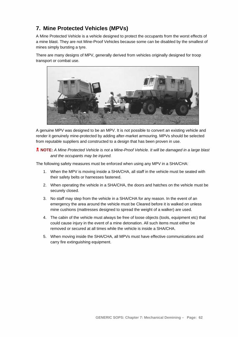
7. Mine Protected Vehicles (MPVs) A Mine Protected Vehicle is a vehicle designed to protect the occupants from the worst effects of a mine blast. They are not Mine-Proof Vehicles because some can be disabled by the smallest of mines simply bursting a tyre.
There are many designs of MPV, generally derived from vehicles originally designed for troop transport or combat use.
A genuine MPV was designed to be an MPV. It is not possible to convert an existing vehicle and render it genuinely mine-protected by adding after-market armouring. MPVs should be selected from reputable suppliers and constructed to a design that has been proven in use.
NOTE: A Mine Protected Vehicle is not a Mine-Proof Vehicle. It will be damaged in a large blast and the occupants may be injured.
The following safety measures must be enforced when using any MPV in a SHA/CHA:
1. When the MPV is moving inside a SHA/CHA, all staff in the vehicle must be seated with their safety belts or harnesses fastened.
2. When operating the vehicle in a SHA/CHA, the doors and hatches on the vehicle must be securely closed.
3. No staff may step from the vehicle in a SHA/CHA for any reason. In the event of an emergency the area around the vehicle must be Cleared before it is walked on unless mine cushions (mattresses designed to spread the weight of a walker) are used.
4. The cabin of the vehicle must always be free of loose objects (tools, equipment etc) that could cause injury in the event of a mine detonation. All such items must either be removed or secured at all times while the vehicle is inside a SHA/CHA.
5. When moving inside the SHA/CHA, all MPVs must have effective communications and carry fire extinguishing equipment.
GENERIC SOPS: Chapter 7: Mechanical Demining – Page: 62
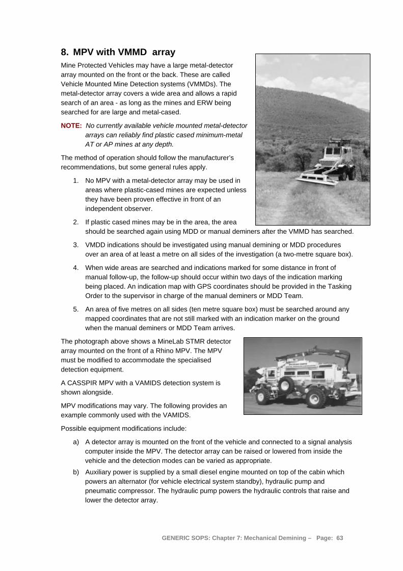
8. MPV with VMMD array Mine Protected Vehicles may have a large metal-detector array mounted on the front or the back. These are called Vehicle Mounted Mine Detection systems (VMMDs). The metal-detector array covers a wide area and allows a rapid search of an area - as long as the mines and ERW being searched for are large and metal-cased.
NOTE: No currently available vehicle mounted metal-detector arrays can reliably find plastic cased minimum-metal AT or AP mines at any depth.
The method of operation should follow the manufacturer’s recommendations, but some general rules apply.
1. No MPV with a metal-detector array may be used in areas where plastic-cased mines are expected unless they have been proven effective in front of an independent observer.
2. If plastic cased mines may be in the area, the area should be searched again using MDD or manual deminers after the VMMD has searched.
3. VMDD indications should be investigated using manual demining or MDD procedures over an area of at least a metre on all sides of the investigation (a two-metre square box).
4. When wide areas are searched and indications marked for some distance in front of manual follow-up, the follow-up should occur within two days of the indication marking being placed. An indication map with GPS coordinates should be provided in the Tasking Order to the supervisor in charge of the manual deminers or MDD Team.
5. An area of five metres on all sides (ten metre square box) must be searched around any mapped coordinates that are not still marked with an indication marker on the ground when the manual deminers or MDD Team arrives.
The photograph above shows a MineLab STMR detector array mounted on the front of a Rhino MPV. The MPV must be modified to accommodate the specialised detection equipment.
A CASSPIR MPV with a VAMIDS detection system is shown alongside.
MPV modifications may vary. The following provides an example commonly used with the VAMIDS.
Possible equipment modifications include:
a) A detector array is mounted on the front of the vehicle and connected to a signal analysis computer inside the MPV. The detector array can be raised or lowered from inside the vehicle and the detection modes can be varied as appropriate.
b) Auxiliary power is supplied by a small diesel engine mounted on top of the cabin which powers an alternator (for vehicle electrical system standby), hydraulic pump and pneumatic compressor. The hydraulic pump powers the hydraulic controls that raise and lower the detector array.
GENERIC SOPS: Chapter 7: Mechanical Demining – Page: 63
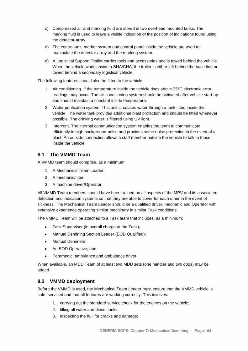
c) Compressed air and marking fluid are stored in two overhead mounted tanks. The marking fluid is used to leave a visible indication of the position of indications found using the detector-array.
d) The control-unit, marker system and control panel inside the vehicle are used to manipulate the detector array and the marking system.
e) A Logistical Support Trailer carries tools and accessories and is towed behind the vehicle. When the vehicle works inside a SHA/CHA, the trailer is either left behind the base-line or towed behind a secondary logistical vehicle.
The following features should also be fitted to the vehicle:
1. Air conditioning. If the temperature inside the vehicle rises above 35°C electronic error-readings may occur. The air-conditioning system should be activated after vehicle start-up and should maintain a constant inside temperature.
2. Water purification system. This unit circulates water through a tank fitted inside the vehicle. The water tank provides additional blast protection and should be fitted whenever possible. The drinking water is filtered using UV light.
3. Intercom. The internal communication system enables the team to communicate efficiently in high background-noise and provides some noise protection in the event of a blast. An outside connection allows a staff member outside the vehicle to talk to those inside the vehicle.
8.1 The VMMD Team A VMMD team should comprise, as a minimum:
1. A Mechanical Team Leader;
2. A mechanic/fitter;
3. A machine driver/Operator.
All VMMD Team members should have been trained on all aspects of the MPV and its associated detection and indication systems so that they are able to cover for each other in the event of sickness. The Mechanical Team Leader should be a qualified driver, mechanic and Operator with extensive experience operating similar machinery in similar Task conditions.
The VMMD Team will be attached to a Task team that includes, as a minimum:
• Task Supervisor (in overall charge at the Task);
• Manual Demining Section Leader (EOD Qualified);
• Manual Deminers;
• An EOD Operative; and
• Paramedic, ambulance and ambulance driver.
When available, an MDD Team of at least two MDD sets (one handler and two dogs) may be added.
8.2 VMMD deployment Before the VMMD is used, the Mechanical Team Leader must ensure that the VMMD vehicle is safe, serviced and that all features are working correctly. This involves:
1. carrying out the standard service check for the engines on the vehicle; 2. filling all water and diesel tanks; 3. inspecting the hull for cracks and damage;
GENERIC SOPS: Chapter 7: Mechanical Demining – Page: 64
4. inspecting all panels, hinges, latches and locks for serviceability; 5. inspecting the windows for cracks and signs of deterioration; 6. inspecting impact absorbent seat cushions and restraining harnesses; 7. ensuring that all bins containing accessories and equipment are properly packed and
secured (they should not restrict the movement of staff); 8. ensuring that there are no loose items inside the vehicle and removing any equipment
not essential for the particular Task; 9. ensuring that all exit hatches are accessible and functioning; 10. ensuring that fire-fighting equipment is charged, in working order and properly
fastened;
11. preparing a safe calibration area on a level ground surface that is away from power lines and any other electromagnetic interference. The calibration area must measure at least 6 x 4 metres and should be marked around its perimeter with painted stones or pickets lying on the ground; and
12. preparing a detector Test area on a level ground surface that is away from power lines and any other electromagnetic interference. The test area must measure at least 6 x 4 metres and should be marked around its perimeter with painted stones or pickets lying on the ground. One of each type of mine that is anticipated at the Task must be rendered safe (leaving all metal inside) and buried at the required Clearance depth in the Test area.
When this has been completed, the VMMD array must also be checked by performing a self test of each of the following units:
• The detector array and control unit.
• The marking unit and associated marking nozzles.
• The system console and its programs.
With the self-tests completed, the marking fluid containers must be filled and the valves must be checked to ensure that they are in working order.
Before using the machine:
1. Ensure that all system electrical switches are “off” and start the vehicle in the manner described in its operation manual. Warm up the engine and let system air pressure build up.
2. Start the detector array by switching electrics “On” and Computer “On”.
3. Activate the Control unit circuit breakers on the Power Card Module faceplate.
4. Verify that the “PWR” and “+ 5V” LEDs are lit. Verify that the “Alarm” and “Active” LEDs on the Sensor card are lit.
5. When the Operating system has loaded, open the “VAMIDS” Program. Type the password (If set).
6. From the SYSTEM SETTINGS menu:
• Verify the number of detection heads. • Check the Shaft Encoder status. • Check the Marking Fluid control status. • Ensure that Auto save On/Off is set to “Off”. • Select the ALARM Type and Level.
7. Activate “START UP” to initialise the array. Wait until the last of a series of messages disappears before continuing.
8. Press “OFF SET” to equalise background.
GENERIC SOPS: Chapter 7: Mechanical Demining – Page: 65
9. Test the operation of each detection head using the test piece and observing the bar graph (Marking “Off”).
10. Complete the “Settings” and “Static test” and then position the array in the centre of the calibration block. Zero “Set sensitivity” and “Calibrate” the system.
11. Move a metal object over it to confirm the operation of each marking nozzle.
12. Adjust final settings whilst in the calibration area. When the Operator confirms “System operational” and “Stable” move to the detector-test area.
13. Move the array over the detector test area and the buried target mine(s). If the detector does not signal, adjust the settings and try again. If the detector cannot be made to give a clear signal on the target mine(s), the VMMD system cannot be used on this Task.
When the VMMD system has detected the target mine(s), the machine can be moved to the start-line.
8.3 Road search with the VMMD The VMMD must be used to search the road to the width and depth specified in the Tasking Order. When necessary, vegetation should be removed over the entire search area before the VMMD is deployed. Generally this should be done using another demining machine.
The following rules must be applied:
1. All members of the VMMD Team must be seated and restrained with harnesses for the entire time that the VMMD is inside the SHA/CHA.
2. The search head advance must be slow enough to ensure detection of the anticipated devices. All passes with the detector array must be overlapped by at least half a metre.
3. The MPV should start from a marked base-line referenced to the Task benchmark and drive forward slowly for 100 metres.
4. It should then reverse along the same tracks to the base-line, move sideways and drive forward again with the detector array overlapping a previous wheel track on one side.
5. This side-step search should be repeated until the search width for the Task is achieved.
6. The machine should then be driven forward and stops with the detector array at least a metre behind the extent of the previous search. The search process should begin again at Step 3.
When the extent of a search is not obvious from visible wheel tracks, paint may be used to mark the ground or painted markers can be dropped onto ground already searched.
7. When the VMMDS marks an area on the road, the VMMDS team must tell the Task Supervisor the GPS reading of the marked area and ask for manual deminers or MDD to investigate the indication.
The Paramedic should not be more than five minutes drive (in an MPV) from the VMMDS team. If the Paramedic is further back, the VMMD team should stop work and wait for the base-line to be advanced.
8.3.1 Investigating a VMMD indication on a road
When the supporting deminers have been told the GPS reading and the position of the marking paint on the road, they should move forward to the working distance for an AP blast mine threat from the indication. When necessary, the Task Supervisor should organise the closure of the road by putting marking across the road at five metres from the indication. When a road surface is compacted, painted stones can be the most practical marking.
GENERIC SOPS: Chapter 7: Mechanical Demining – Page: 66

When MDD are available, the MDD must search from the road closure marking using an approved search pattern described in Chapter 8 of these SOPs. Two MDD sets should be used.
The search width must be the width of required Clearance at the task. The search length should ensure that an area five metres beyond the indication is searched.
When the MDD indicates, the indication should be investigated following Spot Task procedures described in Chapter 6, Part 3.2.2 of these SOPs.
When no MDD are available, a deminer should breach out from a base-line five metres from the signal investigation using manual demining procedures described in Chapter 6 of these SOPs. When the breach reaches five metres in length, the deminer should withdraw and start a lane alongside the first. When the breach is ten metres long and two metres wide, the deminer will have searched to five metres beyond the indication. If the source of the indication has been discovered, the signal investigation is complete. If the source of the indication has not been discovered, the manual deminer should extend the breach on both sides of the indication until an area of 4 x 10 metres centred on the paint marking left by the VMMD has been Cleared.
If the source of the indication is discovered, an area at least two metres on all sides of the source should be Cleared before the signal investigation is completed. When an area 40 metres square has been Cleared and nothing has been discovered, the signal investigation has been completed. Search areas can be reduced when there is total confidence in the accuracy of the positioning of VMMDS indications
The Section Leader should record the result of the investigation, collect all marking and equipment and prepare to move forward to the next investigation.
8.4 Task consolidation On completion of the VMMD Task, the Mechanical Team Leader should compile performance data using the required internal reports. When required, the Team Leader should also enter the data on IMSMA forms for submission to the NMAA. Detailed maps of the area covered and the position of all indications should be included in the Mechanical Team Leader’s completion report and entered in the Task Folder. All reports must be passed to the Task Supervisor before the VMMD Team leaves the Task.
GENERIC SOPS: Chapter 7: Mechanical Demining – Page: 67

9. MPV with REST system A REST system is a Remote Explosive Scent Tracing (REST) detection system. REST relies on the fact that high explosive vapour occurs in the air in areas where there are explosive devices, even when those devices are deeply buried. Samples of the air are taken and presented to highly trained dogs that are in a perfect environment for dogs to work. This can be a very cost-effective way of reducing areas on a road (or linear tasks) where there is a need to deploy manual demining or MDD assets to the minimum.
The success of the system relies on the accurate recording of each sample so that a positive indication can be investigated by manual or MDD procedures long after the MPV with REST system has moved on.
It is absolutely necessary that REST is conducted with scientific rigour and discipline. The samples must be analysed in a dedicated laboratory under strictly controlled conditions. It would not be economic or sensible to try to establish these facilities for single Tasks so the REST facility should be hired from a commercial vendor. Use of a REST system can only be considered when its use would be integrated with other demining assets to ensure rapid investigation of areas that are contaminated.
The SOP below is derived from parts of the commercial demining company MECHEM’s extensive SOPs for the original MPV REST system, named MEDDS. Any errors or omissions in this version are not MECHEM’s responsibility. This SOP must be revised to suit any specific REST system that is used.
9.1 REST using MEDDS sampling MEDDS Sampling is the collection of air samples from a SHA by drawing the air through MEDDS Filter Tubes. Vacuum is created by a vacuum pump mounted inside the MPV and is used to suck a high volume of air through each filter tube. The filter tubes are mounted on flexible rubber hoses fitted close to the ground by the front or rear wheels (one tube on each side of the vehicle). Filter tubes are changed at regular measured intervals without the Operator leaving the vehicle.
When necessary, and in areas with no anticipated AP mines or movement sensitive ERW, hand held sampling can be conducted to augment vehicle mounted sampling. This may be especially appropriate when a road surface does not have an AP threat, so manual sampling of the road surface can be conducted while vehicle mounted sampling of the verges is conducted.
9.1.1 Constraints on using an MPV with MEDDS sampling
The following constraints apply to the deployment of the MEDDS:
1. MEDDS should not be deployed in an area where there is a high risk of AT mines because the MPV may drive over the mines - unless the risk of damage to the MPV is considered acceptable.
2. MEDDS should not be used in an area known to contain AP mines because, if the presence of mines is already known, there is no need to deploy the MEDDS in the area.
3. In areas with dense vegetation, the vegetation must be removed before deploying MEDDS.
4. The MPV can only take samples in areas that it can access. It cannot take samples in dense vegetation or over steep and uneven ground.
5. Entirely reliable logistical support and communication channels must be in place to take samples to the laboratory for analysis and for the efficient return of results.
6. The machine samples the air to four metres on both sides of a centre-line in one pass, so samples an eight metre wide area. Multiple passes will be needed to sample a wider area.
GENERIC SOPS: Chapter 7: Mechanical Demining – Page: 68
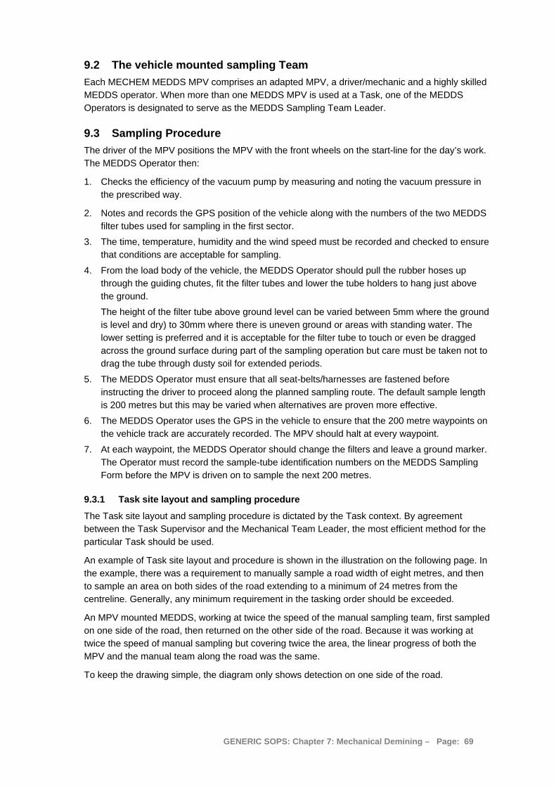
9.2 The vehicle mounted sampling Team Each MECHEM MEDDS MPV comprises an adapted MPV, a driver/mechanic and a highly skilled MEDDS operator. When more than one MEDDS MPV is used at a Task, one of the MEDDS Operators is designated to serve as the MEDDS Sampling Team Leader.
9.3 Sampling Procedure The driver of the MPV positions the MPV with the front wheels on the start-line for the day’s work. The MEDDS Operator then:
1. Checks the efficiency of the vacuum pump by measuring and noting the vacuum pressure in the prescribed way.
2. Notes and records the GPS position of the vehicle along with the numbers of the two MEDDS filter tubes used for sampling in the first sector.
3. The time, temperature, humidity and the wind speed must be recorded and checked to ensure that conditions are acceptable for sampling.
4. From the load body of the vehicle, the MEDDS Operator should pull the rubber hoses up through the guiding chutes, fit the filter tubes and lower the tube holders to hang just above the ground.
The height of the filter tube above ground level can be varied between 5mm where the ground is level and dry) to 30mm where there is uneven ground or areas with standing water. The lower setting is preferred and it is acceptable for the filter tube to touch or even be dragged across the ground surface during part of the sampling operation but care must be taken not to drag the tube through dusty soil for extended periods.
5. The MEDDS Operator must ensure that all seat-belts/harnesses are fastened before instructing the driver to proceed along the planned sampling route. The default sample length is 200 metres but this may be varied when alternatives are proven more effective.
6. The MEDDS Operator uses the GPS in the vehicle to ensure that the 200 metre waypoints on the vehicle track are accurately recorded. The MPV should halt at every waypoint.
7. At each waypoint, the MEDDS Operator should change the filters and leave a ground marker. The Operator must record the sample-tube identification numbers on the MEDDS Sampling Form before the MPV is driven on to sample the next 200 metres.
9.3.1 Task site layout and sampling procedure
The Task site layout and sampling procedure is dictated by the Task context. By agreement between the Task Supervisor and the Mechanical Team Leader, the most efficient method for the particular Task should be used.
An example of Task site layout and procedure is shown in the illustration on the following page. In the example, there was a requirement to manually sample a road width of eight metres, and then to sample an area on both sides of the road extending to a minimum of 24 metres from the centreline. Generally, any minimum requirement in the tasking order should be exceeded.
An MPV mounted MEDDS, working at twice the speed of the manual sampling team, first sampled on one side of the road, then returned on the other side of the road. Because it was working at twice the speed of manual sampling but covering twice the area, the linear progress of both the MPV and the manual team along the road was the same.
To keep the drawing simple, the diagram only shows detection on one side of the road.
GENERIC SOPS: Chapter 7: Mechanical Demining – Page: 69
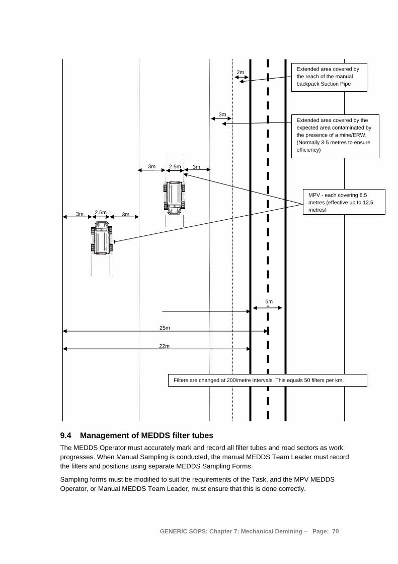
25m
6m
22m
2m Extended area covered by the reach of the manual backpack Suction Pipe
Filters are changed at 200\metre intervals. This equals 50 filters per km.
Extended area covered by the expected area contaminated by the presence of a mine/ERW. (Normally 3-5 metres to ensure efficiency)
3m 3m 2.5m
MPV - each covering 8.5 metres (effective up to 12.5 metres)
3m 3m2.5m
3m
9.4 Management of MEDDS filter tubes The MEDDS Operator must accurately mark and record all filter tubes and road sectors as work progresses. When Manual Sampling is conducted, the manual MEDDS Team Leader must record the filters and positions using separate MEDDS Sampling Forms.
Sampling forms must be modified to suit the requirements of the Task, and the MPV MEDDS Operator, or Manual MEDDS Team Leader, must ensure that this is done correctly.
GENERIC SOPS: Chapter 7: Mechanical Demining – Page: 70
At the end of every working day the MEDDS Sampling Team Leader must check the forms and collect the filters for transport to the laboratory for analysis. He/she must check that the GPS coordinates match the filter tubes using MECHEM’s internal random-check QA system.
9.4.1 Prevention of Contamination
Because the MEDDS dogs that examine the filters work at extremely low odour concentrations, the potential for trace contamination of the filters by staff must be minimised. There must also be no cross contamination from filter to filter. Handling and movement of filters must always be reduced to the absolute minimum, and handling should be conducted using single-use gloves.
During the sampling process the following anti-contamination measures must be strictly observed:
1. MEDDS filter tubes must never be touched with bare hands. The tubes must always be handled by the outer container and while using disposable gloves. Disposable gloves must be replaced after handling each tube.
2. Outer containers of sampled tubes must be handled with extreme care because contamination could spill out of the tube. The container lid must be kept on at all times (even when the tube is not in the tube container).
3. The hands of all people in contact with the samples must be thoroughly washed under running water at regular intervals during the sampling process.
4. The MEDDS filter holder (at the front of the sampling rod) must be washed under clean running water at regular intervals during the sampling process.
5. Care must be taken that filter tubes are always placed back into the containers with corresponding numbers. Any accidental placement of a used tube into another container could “cross contaminate” the container and must be avoided.
6. If a filter tube is accidentally dropped, care must be taken not to “scoop” soil/dust into the container in the process of retrieving it using single-use gloves.
7. MEDDS filter tubes (used or unused) must always be stored in the plastic boxes provided and care must be taken not to contaminate stored tubes. Tubes must always be kept well away from all strong smelling substances and especially any source of explosive vapour. This includes all weapons and ammunition and anything that has had close contact with explosives such as explosive packaging, boxes etc.
8. If there is any uncertainty over whether contamination/cross-contamination has taken place, this must be recorded and reported to the MEDDS Team Leader. Depending on the circumstances and the results of the analysis, the MEDDS Team Leader may require the areas affected to be re-sampled. If it is likely that samples have been contaminated when filter tubes are being changed, the contaminated tubes should be set aside and the relevant area re-sampled immediately.
9.5 Traffic regulation during sampling Where routes being sampled are being used by normal traffic, strict measures must be put in place to regulate traffic on the road. This is not only important to ensure the safety of the sampling teams, but also to ensure that travellers on the road are not endangered by the activities of the sampling teams.
The MEDDS Team Leader is responsible for all traffic regulation and safety on the site and where necessary should use staff as traffic controllers. It is the responsibility of each member of the sampling team to contribute towards the prevention of accidents.
GENERIC SOPS: Chapter 7: Mechanical Demining – Page: 71

9.6 Internal MEDDS QA and QC The MEDDS Team Leader is responsible for all aspects of sampling and for ensuring that, when anything may have compromised the samples taken, the samples for affected sector(s) are discarded and the area(s) re-sampled.
The MEDDS Team Leader must ensure that all manual samplers:
a. Check the vacuum pressure of the sampling machine before the start of the day’s work and ensure that it is operating properly;
b. Never become directly involved in the actual changing of tubes at the beginning/end of sectors. This must be done by the MEDDS Team Leader or delegated recorder. The sampling machine Operator should never touch any MEDDS Tubes during the sampling process;
c. Keeps the sampling head/filter tube as close as possible to the ground during the sampling process;
d. Maintains an arc of swing as close as possible to 180° for each step forward to ensure the best possible ground coverage;
e. Drags the filter tube through any vegetation on the verges of the road in order to maximise the odour collection process; and
f. Washes the sampling nozzle under clean running water at regular intervals to prevent cross contamination.
The MEDDS Team Leader must ensure the accurate completion of all “Sampling Forms” and confirm the accuracy of recorded information on a regular basis.
9.6.1 The Tubes
The MEDDS Team Leader is responsible for ensuring that:
a. No seal on the lid of any unused tube is broken until it is needed;
b. No samples are taken using a tube on which the seal was not intact until deliberately broken for use;
c. All used and unused filter tubes are properly stored and kept free of contamination by explosives, weapons and ammunition. They must be kept away from any potential contaminant and not transported in a vehicle in which potential contaminants have been transported;
d. All used tubes are placed back in their original tube containers, that these are properly closed and placed back into the original container boxes and properly stored (away from all strong smelling substances); and
e. All sampled filter tubes are transported to a designated collection point as soon as possible ensuring that the potential for contamination of the samples (and packing) is minimised.
9.6.2 GPS
The Sampling Team Leader must ensure the accuracy of the surveying/marking of the start and end points of sectors by regularly double checking the GPS waypoint detail – and then cross check this with the recording on the sampling forms.
GENERIC SOPS: Chapter 7: Mechanical Demining – Page: 72