the imagestream wan card driver suite for linux - … · 2013-09-05 · the imagestream wan card...
TRANSCRIPT

The ImageStream WAN CardDriver Suite For Linux
Compatible with all SBS Aries, WANic series cardsPPP, Cisco HDLC, Frame Relay, Raw IP, X.25
Includes SAND-compatible Linux Driver Version 3.00 or later releaseTuesday, March 06, 2001

2
Table Of Contents Frequently used chapters are displayed in BOLD
TABLE OF CONTENTS ............................................................................................................................ 2
GENERAL INFORMATION .................................................................................................................... 4
ACCURACY.................................................................................................................................................4WARRANTY................................................................................................................................................4SALES AND TECHNICAL SUPPORT.......................................................................................................4TRADEMARKS ...........................................................................................................................................5FCC CLASS A LIMITS................................................................................................................................5CANADIAN DEPARTMENT OF COMMUNICATIONS CLASS A LIMITS ..........................................5FCC PART 68 RULE DISCLOSURE ..........................................................................................................6
I. INTRODUCTION AND PREPARING FOR INSTALLATION ...................................................... 7
INTRODUCTION..............................................................................................................................................7UNPACKING THE CARD .................................................................................................................................7
II. HARDWARE CONFIGURATION FOR THE RISCOM/N2X SERIES CARD ........................... 8
IRQ JUMPERS ................................................................................................................................................8I/O BASE ADDRESS .......................................................................................................................................8
III. INSTALLING THE IMAGESTREAM WAN CARD DRIVER SUITE FOR LINUX ................ 9
PRE-INSTALLATION INFORMATION............................................................................................................9GETTING STARTED ....................................................................................................................................10
IV. CONFIGURING THE IMAGESTREAM WAN CARD DRIVER SUITE FOR LINUX .......... 12
UNDERSTANDING THE “ WAN.CONF” CONFIGURATION FILE ...................................................................13UNDERSTANDING FRAME RELAY CONFIGURATIONS ..............................................................................15UNDERSTANDING THE IMAGESTREAM “STATS” PROGRAM ........................................................................17DETAIL SCREEN FIELD DESCRIPTIONS ........................................................................................................19USING IMAGESTREAM’S BONDER FOR LINK AGGREGATION/LOAD BALANCING ...................................22
V. TROUBLESHOOTING .................................................................................................................... 24
TECHNICAL SUPPORT ..................................................................................................................................26
VI. APPENDIX A – PRODUCT RETURN PROCEDURES .............................................................. 27

3
FACTORY REPAIR ........................................................................................................................................27RE-PACKING GUIDELINES FOR EQUIPMENT RETURN ..................................................................................27SPECIFIC PACKING GUIDELINES ..................................................................................................................28
VII. APPENDIX B – NETMASK CONVERSION TABLE ................................................................ 29
VIII. APPENDIX C – CABLES AND ADAPTERS ............................................................................. 30
RS-232 ADAPTER CABLE ............................................................................................................................30V.35 ADAPTER CABLE ................................................................................................................................31RS-422 ADAPTER CABLE ............................................................................................................................32RS-449 ADAPTER CABLE ............................................................................................................................33X.21 ADAPTER CABLE ................................................................................................................................34RJ48 LOOP BACK PLUG...............................................................................................................................35RJ48C TO RJ48C CROSSOVER (LOOPBACK) CABLE...................................................................................36DB26 TO DB26 CROSSOVER (LOOPBACK) CABLE .....................................................................................37
IX. APPENDIX D – T1 BASICS ............................................................................................................ 38
WHAT IS A T1 LINE?...................................................................................................................................38HOW CAN A T1 BE USED?..........................................................................................................................38WHAT IS A CSU/DSU? ................................................................................................................................38CSU/DSU ALARMS.....................................................................................................................................38WHAT NEEDS TO BE CONFIGURED FOR A CSU TO WORK?..........................................................................39AMI VERSUS B8ZS LINE CODING...............................................................................................................39

4
General Information
ImageStream Internet Solutions7900 East 8th RoadPlymouth, IN 46563
(219) 935-8484
The information contained in this manual is proprietary in nature, and may not beduplicated, in whole or in part, for any purpose, without prior written consent ofImageStream. Receipt of this manual is considered acceptance of these conditions.
ACCURACY
All information in this manual is based on the latest product information available at thetime of printing. ImageStream has carefully reviewed the accuracy of this manual, butcannot be held liable for omissions or errors that may appear. ImageStream reservesthe right to revise this publication and to make changes in its contents without obligationof notifying any persons of such revision changes.
WARRANTY
ImageStream Internet Solutions, Inc. warrants that at the time of shipment the routerproduct and its installed components shall be free from defect in material andworkmanship. ImageStream Internet Solutions, Inc. warrants that the router will meetthe product’s standard specifications at the time of shipment. This warranty excludesdamage resulting from mishandling, tampering, improper installation and misuse by thepurchaser.
ImageStream Internet Solutions, Inc. warrants the router for a period of 1 year from theinvoice date. For warranty claims, contact your place of purchase, or ImageStreamInternet Solutions, Inc. immediately upon the discovery of such defect. If theRouter or its installed components are found to be defective, ImageStream InternetSolutions, Inc. will repair or replace the router at ImageStream’s option.
In no event shall ImageStream Internet Solutions, Inc., be liable for direct, indirect,incidental or consequential damages in connection with, or arising from, the furnishing,performance, or use of the router. Purchaser may have other rights that vary from stateto state.
SALES AND TECHNICAL SUPPORT
ImageStream’s on-line resources provide the latest information on software driverupgrades, frequently asked questions and other issues. These services are available 24hours a day, 7 days a week via FTP at ftp.imagestream-is.com and on the World WideWeb at http://www.imagestream-is.com/

5
The ImageStream Support Team is available Monday through Friday between the hoursof 8:00 a.m. and 5:00 p.m. Eastern Time. For phone support please call219-935-8484. The ImageStream fax number is 219-935-8488. For email supportplease send mail to [email protected].
TRADEMARKS
PC, PC-XT & PC-AT are trademarks of International Business Machines.MS-DOS is a trademark of Microsoft Corporation.UNIX is a registered trademark of AT&T Bell Labs.Aries, Maxim, WANic and RISCom are registered trademarks of SBS Technologies, Inc.
FCC CLASS A LIMITS
Warning: Changes or modifications to this unit not expressly approved by the partyresponsible for compliance could void the user’s authority to operate the equipment.
Note: This equipment has been tested and found to comply with the limits for aClass A digital device pursuant to Part 15 of the FCC Rules. These limits are designedto provide reasonable protection against harmful interference when the equipment isoperated in a commercial environment. This equipment generates, uses, and canradiate radio frequency energy and, if not installed and used in accordance with theinstruction manual, may cause harmful interference to radio communications. Operationof the equipment in a residential area is likely to cause harmful interference in whichcase the user will be required to correct the interference at his own expense.
Shielded cables must be used with this unit to ensure compliance with FCCClass A limits.
CANADIAN DEPARTMENT OF COMMUNICATIONS CLASS A LIMITS
This digital apparatus does not exceed the Class A limits for radio noise emissions fromdigital apparatus set out in the Radio Interference Regulations of the CanadianDepartment of Communications.
Le present appareil numerique n’emet pas de bruits radioelectriques depassantles limites applicables aux appareils numeriqqes de la class A prescritesdans le Reglement sur le brouillage radioelectrique edicte par le ministeredes Communications du Canada.
DS&G Registration Number - US Safety:Canadian Use Registration Number:CSA Registration Number - Canadian Safety:FCC Registration Number

6
FCC PART 68 RULE DISCLOSURE
The following information is required by FCC Part 68 Rules which informs the user ofhis rights and obligations in connecting this equipment to the network and in orderingservice.
This equipment complies with Part 68 of FCC Rules. Please note the following:
1. When you order service, the telephone company needs to know:
a. The Facility Interface Code:04DU-B (1.544 MB D4 framing format)04DU9-C (1.544 MB ESF framing format)
b. The Service Order Code: 6.0F
A signal power affidavit may be required to guarantee encoded analog content andbilling protection unless this unit is used in combination with and XD type device or noencoded analog signals and billing information are transmitted.
c. The USOC Jack Required: RJ48C
In addition, if requested, please inform the telephone company of the make, model andFCC Registration Number, which are on the label.
2. Your telephone company may make changes in its facilities, equipment, operations orprocedures that could affect the proper functioning of your equipment. If they do, youwill be notified in advance to give you and opportunity to maintain uninterruptedtelephone service.
3. If your telephone equipment causes harm to the telephone network, the telephonecompany may discontinue your service temporally. If possible, they will notify you inadvance, but if advance, but if advance notice is not practical, you will be notified assoon as possible. You will be informed of your right to file a complaint with the FCC.
4. If you experience trouble with the telephone equipment, please contact us forinformation on obtaining service or repairs. Only ImageStream or our authorized agentsshould perform repairs.
5. You are required to notify the telephone company when this unit is disconnectedfrom the network.

7
I. Introduction And Preparing For Installation
Introduction
This section outlines the procedure for unpacking, configuring, installing and testing theWANic or RISCom/N2x for operation in a PC. It is assumed that the installer is familiarwith the basic layout and operation of a PC Compatible computer.
Please read this entire manual before contacting ImageStream for technicalassistance. Please report any errata or change recommendations [email protected].
Unpacking The Card
Though a WAN card is shipped in a sturdy cardboard box with foam padding, it maybedamaged in shipping. We suggest that each box and its contents be examined for visualdamage. If your shipment arrives damaged, incomplete, or incorrect, contactImageStream Internet Solutions immediately.
Care must be taken in handling the card. It contains parts that may be damaged byElectric Static Discharge (ESD). It is suggested that the installer uses proper safety andgrounding precautions prior to removing the card from the ESD protective bag.
The following items are typically shipped in a card box. However, the packing listshould be reviewed to verify the completeness of the shipment:
Cards without integrated CSU/DSUsa. WAN card with RS232, EIA-530 or V.35 interface optionsb. RS232, RS449, EIA530 or V.35 Adapter Cable (if ordered)c. 3.5 Inch Diskette Software Drivers and Diagnostics (if ordered)
Cards with integrated CSU/DSUsa. WAN card with CSU and RS232, EIA-530 or V.35 interface options (if any)b. RS232, RS449, EIA530 or V.35 Adapter Cable (if ordered)c. 3.5 Inch Diskette Software Drivers and Diagnostics (if ordered)d. RJ48 Loop Back Plug (if ordered)
The Ethernet (100BaseTX/10BaseT), Token Ring, serial and console ports containsafety extra-low voltage (SELV) circuits. T1, 56 Kbps (DDS), BRI and PRI circuits aretelephone-network voltage (TNV) circuits. Avoid connecting SELV circuits to TNV circuitequipment, such as the WANic and RISCom series cards with integrated CSU/DSUs,as this can cause damage to the equipment.
8
II. Hardware Configuration For The RISCom/N2x Series Card
Unlike the WANic series PCI WAN cards, the RISCom/N2x series cards require pre-configuration before installation. The hardware configuration for the RISCom/N2x cardinvolves setting up the I/O Base Address and selecting the PC Interrupt Level.
Factory Default Settings
Each RISCom/N2x is factory configured and tested with the following configuration:
I/O Base Address (S1): 300HIRQ Jumpers (J1): 5Ceiling Current (J5): ON (N2CSU, N2DDS ONLY)
IRQ Jumpers
The N2x series of cards uses a hardware interrupt (IRQ). The jumper plug providedshould be connected across the appropriate pins. The RISCom/N2x does not supportsharing of interrupts, so an IRQ that does not conflict with other hardware in the systemis required.
Available PC IRQ Selection: 3,4,5,7,10,11,12,15
I/O Base Address
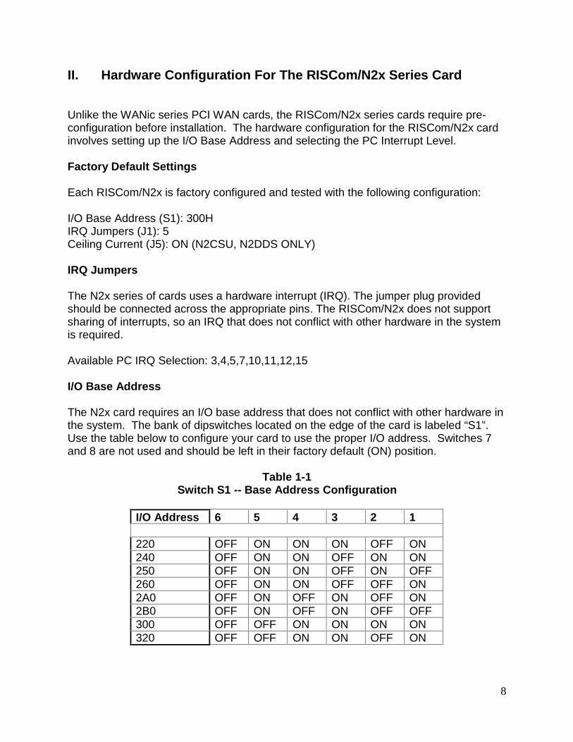
The N2x card requires an I/O base address that does not conflict with other hardware inthe system. The bank of dipswitches located on the edge of the card is labeled “S1”.Use the table below to configure your card to use the proper I/O address. Switches 7and 8 are not used and should be left in their factory default (ON) position.
Table 1-1Switch S1 -- Base Address Configuration
I/O Address 6 5 4 3 2 1
220 OFF ON ON ON OFF ON240 OFF ON ON OFF ON ON250 OFF ON ON OFF ON OFF260 OFF ON ON OFF OFF ON2A0 OFF ON OFF ON OFF ON2B0 OFF ON OFF ON OFF OFF300 OFF OFF ON ON ON ON320 OFF OFF ON ON OFF ON

9
III. Installing the ImageStream WAN Card Driver Suite For Linux
Pre-Installation InformationHave the following information ready before you start
Parameter Where to find it DescriptionI/O Base Address Card dip switches Check card jumpers.
IRQ Card dip switches Check card jumpers.
Local IP address Line Provider The local IP address will bethe address for the specificlink/port (“numbered link”) orprimary Ethernet address(“unnumbered link”) of yourrouter.
Remote IP address Line Provider The local IP address will bethe address for the specificlink/port (“numbered link”)orprimary Ethernet address(“unnumbered link”) of therouter on the other end ofthe link.
Clock Source Line Provider The clock source will eitherbe internal (provided by theWAN card or integratedCSU) or external (providedby a CSU/DSU or by the lineprovider).
Line Encoding/Framing Line Provider If you have a card with anintegrated CSU/DSU, youwill need to know thesevalues. The normalencoding values for will beB8ZS or AMI and normalframing values are ExtendedSuper Frame (“ESF”) orSuper Frame (“SF” or “D4”).
DLCI Number(Frame Relay Only)
Line Provider Used to establish virtualcircuit across frame relaynetwork to remote router.

10
Getting Started
Please read this entire manual before contacting ImageStream for technicalassistance. Please report any errata or change recommendations [email protected].
The first step in the installation is to copy the file from your disk or saved downloadlocation to a convenient directory (i.e. "/usr/local/").
1. "unzip" and "untar" the driver archive file as follows.$ cd /usr/local; tar xzpf <filename>; cd sand
Note: if you do not have GNU tar and this command fails, try:$ gunzip <filename>$ tar xvf <filename>$ cd wanic
2. You will notice that this not only "untarred" the file, but it also created a fewdirectories and files. Among the directories and files created are a sampleconfiguration directory, a documents directory containing this document, a sourcedirectory containing source code to the included statistics program and the pppdaemon as well as several scripts in the base directory:
CHANGES/README:
Outlines recent changes to the driver set, including bug fixes, new hardwaredrivers or protocols and other added features and provides a quick-startinstallation guide to operating the driver set.
LoadModules/UnloadModules:
Scripts used by the driver to load the protocol and WAN card hardware modules.
configmgr:
The controlling program for the WAN card drivers.
debug:
A script that toggles the output of debugging information to the terminal.
display_dlcis/hardware/ports/routes:
Diagnostic programs that display information about your system interfaces.
down:
A script that stops all ports and unloads the WAN card driver completely.

11
hw_debug/proto_debug:
A program used by the driver to control the output of debugging information.
make_devices:
Deletes old device files and creates new ones. Normally, configmgr will handlethe creation of device files. If the “mknod” command is not in your path or if theblock major number is being used by another device in your system, edit thescript and change the path to "mknod" or the major number to reflect the newnumber. This script normally does NOT need to be executed manually.
ppp_routes/ppp_template:
Files used by configmgr to operate a port using the PPP protocol. These scriptsshould not be edited by hand.
pppd:
The ppp daemon, modified for use with synchronous WAN card devices.
reload:
A script that stops all ports, unloads and reloads the driver and restarts all ports.
stats:
The program used by the driver to display configuration and status informationabout the WAN ports in your system.
up:
The script that loads the driver and starts all ports.
wan.conf.default:
A default configuration file for your reference.
3. The default values in the “up” script should work for most systems. You can edit the“up” script to change the debugging level, the device names and the major numberused by the drivers. Aside from changing the debugging level, you will not normallyneed to change anything in this script.
4. Change directories to the “example_configs” directory.
12
IV. Configuring the ImageStream WAN Card Driver Suite For Linux
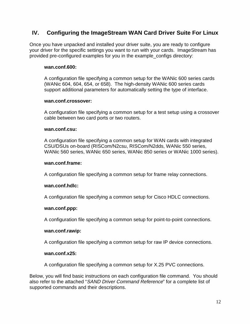
Once you have unpacked and installed your driver suite, you are ready to configureyour driver for the specific settings you want to run with your cards. ImageStream hasprovided pre-configured examples for you in the example_configs directory:
wan.conf.600:
A configuration file specifying a common setup for the WANic 600 series cards(WANic 604, 604, 654, or 658). The high-density WANic 600 series cardssupport additional parameters for automatically setting the type of interface.
wan.conf.crossover:
A configuration file specifying a common setup for a test setup using a crossovercable between two card ports or two routers.
wan.conf.csu:
A configuration file specifying a common setup for WAN cards with integratedCSU/DSUs on-board (RISCom/N2csu, RISCom/N2dds, WANic 550 series,WANic 560 series, WANic 650 series, WANic 850 series or WANic 1000 series).
wan.conf.frame:
A configuration file specifying a common setup for frame relay connections.
wan.conf.hdlc:
A configuration file specifying a common setup for Cisco HDLC connections.
wan.conf.ppp:
A configuration file specifying a common setup for point-to-point connections.
wan.conf.rawip:
A configuration file specifying a common setup for raw IP device connections.
wan.conf.x25:
A configuration file specifying a common setup for X.25 PVC connections.
Below, you will find basic instructions on each configuration file command. You shouldalso refer to the attached “SAND Driver Command Reference” for a complete list ofsupported commands and their descriptions.
13
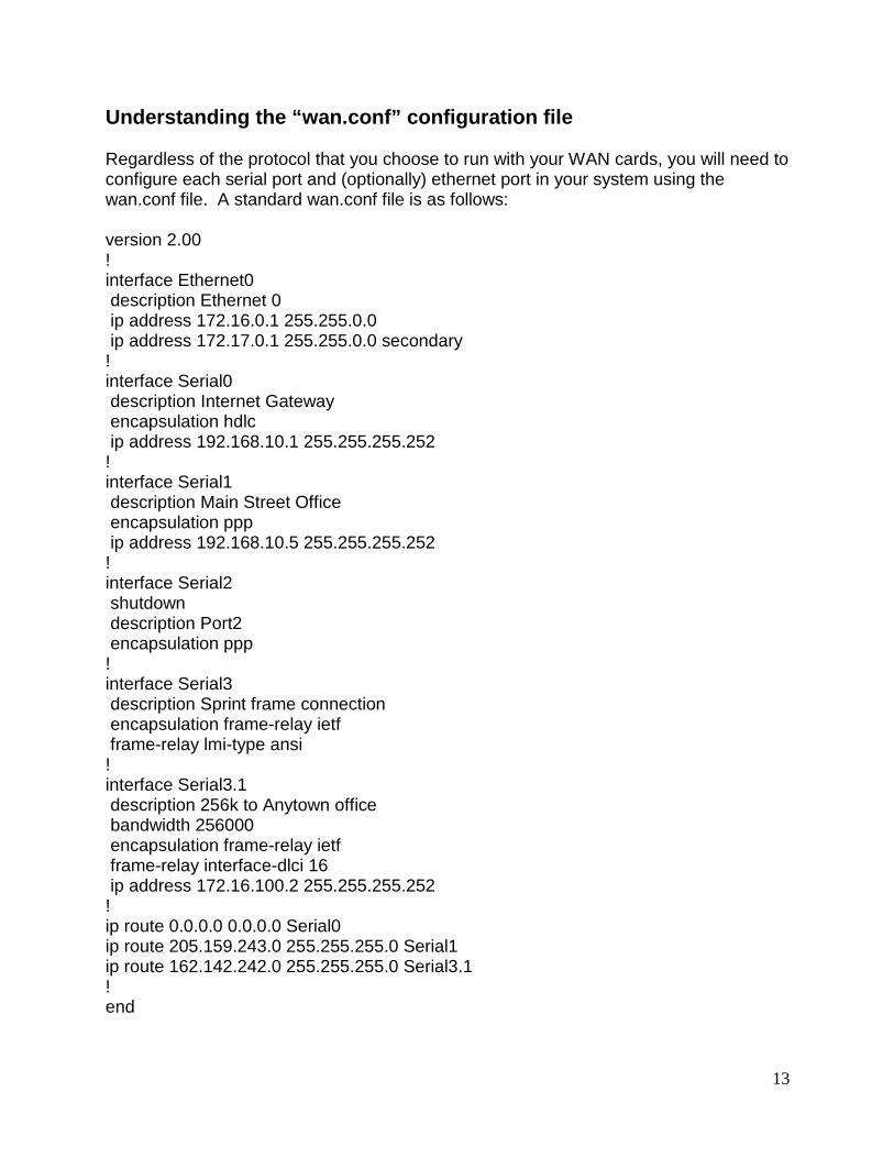
Understanding the “wan.conf” configuration file
Regardless of the protocol that you choose to run with your WAN cards, you will need toconfigure each serial port and (optionally) ethernet port in your system using thewan.conf file. A standard wan.conf file is as follows:
version 2.00!interface Ethernet0 description Ethernet 0 ip address 172.16.0.1 255.255.0.0 ip address 172.17.0.1 255.255.0.0 secondary!interface Serial0 description Internet Gateway encapsulation hdlc ip address 192.168.10.1 255.255.255.252!interface Serial1 description Main Street Office encapsulation ppp ip address 192.168.10.5 255.255.255.252!interface Serial2 shutdown description Port2 encapsulation ppp!interface Serial3 description Sprint frame connection encapsulation frame-relay ietf frame-relay lmi-type ansi!interface Serial3.1 description 256k to Anytown office bandwidth 256000 encapsulation frame-relay ietf frame-relay interface-dlci 16 ip address 172.16.100.2 255.255.255.252!ip route 0.0.0.0 0.0.0.0 Serial0ip route 205.159.243.0 255.255.255.0 Serial1ip route 162.142.242.0 255.255.255.0 Serial3.1!end
14
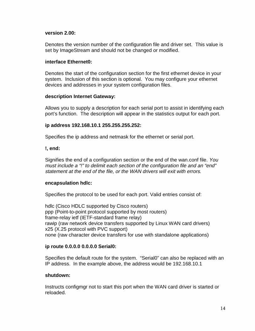
version 2.00:
Denotes the version number of the configuration file and driver set. This value isset by ImageStream and should not be changed or modified.
interface Ethernet0:
Denotes the start of the configuration section for the first ethernet device in yoursystem. Inclusion of this section is optional. You may configure your ethernetdevices and addresses in your system configuration files.
description Internet Gateway:
Allows you to supply a description for each serial port to assist in identifying eachport’s function. The description will appear in the statistics output for each port.
ip address 192.168.10.1 255.255.255.252:
Specifies the ip address and netmask for the ethernet or serial port.
!, end:
Signifies the end of a configuration section or the end of the wan.conf file. Youmust include a “!” to delimit each section of the configuration file and an “end”statement at the end of the file, or the WAN drivers will exit with errors.
encapsulation hdlc:
Specifies the protocol to be used for each port. Valid entries consist of:
hdlc (Cisco HDLC supported by Cisco routers)ppp (Point-to-point protocol supported by most routers)frame-relay ietf (IETF-standard frame relay)rawip (raw network device transfers supported by Linux WAN card drivers)x25 (X.25 protocol with PVC support)none (raw character device transfers for use with standalone applications)
ip route 0.0.0.0 0.0.0.0 Serial0:
Specifies the default route for the system. “Serial0” can also be replaced with anIP address. In the example above, the address would be 192.168.10.1
shutdown:
Instructs configmgr not to start this port when the WAN card driver is started orreloaded.
15
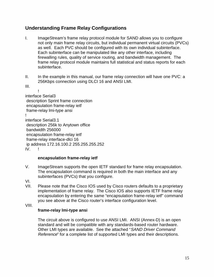
Understanding Frame Relay Configurations
I. ImageStream’s frame relay protocol module for SAND allows you to configurenot only main frame relay circuits, but individual permanent virtual circuits (PVCs)as well. Each PVC should be configured with its own individual subinterface.Each subinterface can be manipulated like any other interface, includingfirewalling rules, quality of service routing, and bandwidth management. Theframe relay protocol module maintains full statistical and status reports for eachsubinterface.
II. In the example in this manual, our frame relay connection will have one PVC: a256Kbps connection using DLCI 16 and ANSI LMI.
III. !
interface Serial3 description Sprint frame connection encapsulation frame-relay ietf frame-relay lmi-type ansi!interface Serial3.1 description 256k to Anytown office bandwidth 256000 encapsulation frame-relay ietf frame-relay interface-dlci 16 ip address 172.16.100.2 255.255.255.252IV. !
encapsulation frame-relay ietf
V. ImageStream supports the open IETF standard for frame relay encapsulation.The encapsulation command is required in both the main interface and anysubinterfaces (PVCs) that you configure.
VI. VII. Please note that the Cisco IOS used by Cisco routers defaults to a proprietary
implementation of frame relay. The Cisco IOS also supports IETF frame relayencapsulation by entering the same “encapsulation frame-relay ietf” commandyou see above at the Cisco router’s interface configuration level.
VIII. frame-relay lmi-type ansi
The circuit above is configured to use ANSI LMI. ANSI (Annex-D) is an openstandard and will be compatible with any standards-based router hardware.Other LMI types are available. See the attached “SAND Driver CommandReference” for a complete list of supported LMI types and their descriptions.
16
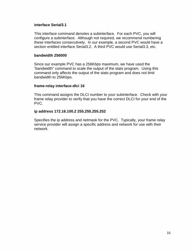
interface Serial3.1
This interface command denotes a subinterface. For each PVC, you willconfigure a subinterface. Although not required, we recommend numberingthese interfaces consecutively. In our example, a second PVC would have asection entitled interface Serial3.2. A third PVC would use Serial3.3, etc.
bandwidth 256000
Since our example PVC has a 256Kbps maximum, we have used the“bandwidth” command to scale the output of the stats program. Using thiscommand only affects the output of the stats program and does not limitbandwidth to 256Kbps.
frame-relay interface-dlci 16
This command assigns the DLCI number to your subinterface. Check with yourframe relay provider to verify that you have the correct DLCI for your end of thePVC.
ip address 172.16.100.2 255.255.255.252
Specifies the ip address and netmask for the PVC. Typically, your frame relayservice provider will assign a specific address and network for use with theirnetwork.

17
Understanding the ImageStream “stats” program
ImageStream’s router distribution includes Linux’s standard “ifconfig” interface program.However, ifconfig was not designed to display status and statistical information forspecialized LAN and WAN devices. ImageStream’s SAND distribution includes aprogram called “stats” that allows you track the status of all of LAN and WAN devicesand view specific information on each interface and sub-interface.
To execute the stats program, return to the Main Menu of your router and choose “Showinterface status”. This will display a screen with one-line summaries of each interfaceand sub-interface in your system.
The summary screen
6:28:38 AM ISis-Router Interface Summary# Port Description Encaps BW HW Proto In Out0 Ether0 100 Mb Ethernet 100.00 Mbps up up 92% 10%1 Serial0 WANic 800 Port 0 none 0.00 bps down down never up2 Serial1 Sprint Frame Relay T1 Frame Relay 256.00 Kbps up up 1% 4%3 Serial1.1 ISis Plymouth 256K 256.00 Kbps up up 1% 4%4 Serial1.2 ISis San Pierre 256K 256.00 Kbps up up 0% 0%5 Serial2 WANic 555 Port 2 PPP 1.54 Mbps up down 15:31:526 Serial3 WANic 850 Port 0 none 0.00 Mbps down shut-------------------------------------------------------------------------------d - Detail s - Sleep interval q – Quit
#
Indicates the number in the summary listed. When selecting the detail option,you will be prompted for this interface number.
Port
IX. This column shows the name of the corresponding device configured in thewan.conf file.
Encaps
Displays the configured encapsulation for the device. Ethernet devices will notshow a value in this column. Devices that have not been configured or that areadministratively shut down will display “none”
BW
Indicates the bandwidth value or channel group configured in wan.conf orlearned from the integrated CSU/DSU on the port. Devices that have not beenconfigured or that are administratively shut down will display “0.00 Mbps”

18
HW
Indicates whether or not the interface hardware connection to the telephonecompany network or external CSU/DSU is active. If carrier is detected on theline, this column will display “up”. If carrier is not detected on the line, or if theinterface has not been configured or administratively shut down, the column willdisplay “down”.
Proto
Indicates whether the software processes that handle the device’s protocolconsider the line usable (that is, whether keepalives are successful) or if it hasbeen taken down by an administrator. If a usable connection has beenestablished, this column will display “up”. If a connection has not beenestablished or the device is not configured, the column will display “down”. If thedevice is administratively shut down, the column will display “shut”.
In/Out
Displays the amount of traffic currently on the interface. The percentagedisplayed is calculated using the sleep interval and bandwidth value on theinterface. If the device is not configured, the columns will display “never up”. Ifthe device is administratively shut down, the columns will not display any values.If the hardware or protocol is down on the device, the length of time since thedevice’s status changed to down will be displayed in the columns.
19
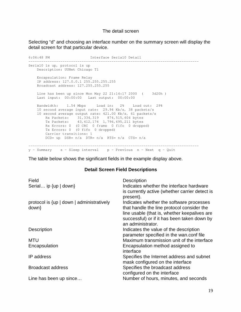
The detail screen
Selecting “d” and choosing an interface number on the summary screen will display thedetail screen for that particular device.
6:06:48 PM Interface Serial0 Detail--------------------------------------------------------------------------------Serial0 is up, protocol is up Description: UUNet Chicago T1
Encapsulation: Frame Relay IP address: 127.0.0.1 255.255.255.255 Broadcast address: 127.255.255.255
Line has been up since Mon May 22 21:14:17 2000 ( 3d20h ) Last input: 00:00:00 Last output: 00:00:00
Bandwidth: 1.54 Mbps Load in: 2% Load out: 29% 10 second average input rate: 29.94 Kb/s, 38 packets/s 10 second average output rate: 421.00 Kb/s, 61 packets/s Rx Packets: 31,334,319 874,515,604 bytes Tx Packets: 43,412,174 1,796,695,211 bytes Rx Errors: 0 (0 CRC 0 frame 0 fifo 0 dropped) Tx Errors: 0 (0 fifo 0 dropped) Carrier transitions: 1 DCD= up DSR= n/a DTR= n/a RTS= n/a CTS= n/a
--------------------------------------------------------------------------------y - Summary s - Sleep interval p - Previous n - Next q – Quit
The table below shows the significant fields in the example display above.
Detail Screen Field Descriptions
Field DescriptionSerial… ip {up | down} Indicates whether the interface hardware
is currently active (whether carrier detect ispresent).
protocol is {up | down | administrativelydown}
Indicates whether the software processesthat handle the line protocol consider theline usable (that is, whether keepalives aresuccessful) or if it has been taken down byan administrator.
Description Indicates the value of the descriptionparameter specified in the wan.conf file
MTU Maximum transmission unit of the interfaceEncapsulation Encapsulation method assigned to
interfaceIP address Specifies the Internet address and subnet
mask configured on the interfaceBroadcast address Specifies the broadcast address
configured on the interfaceLine has been up since… Number of hours, minutes, and seconds

20
since the interface was last reset. Whenthe number of hours in any of the "last"fields exceeds 24 hours, the number ofdays and hours is printed. Interfaces thathave never been up will specify
Last input Number of hours, minutes, and secondssince the last packet was successfullyreceived by an interface.
Last output Number of hours, minutes, and secondssince the last packet was successfullytransmitted by an interface.
Bandwidth Indicates the value of the bandwidthparameter that has been configured for theinterface. If the interface is attached to aserial line with a line speed that does notmatch the default, use the bandwidthcommand to specify the correct line speedfor this serial line.
Load in Inbound load on the interface as a fractionof the bandwidth, calculated as an averageof the specified sleep interval
Load out Outbound load on the interface as afraction of the bandwidth, calculated as anaverage of the specified sleep interval
…second average input rate Actual inbound data rate load on theinterface, calculated as an average of thespecified sleep interval
…second average output rate Actual outbound data rate load on theinterface, calculated as an average of thespecified sleep interval
Rx/Tx Packets Total number of error-free packetsreceived/sent by the system and totalnumber of bytes, including data and MACencapsulation in the error-free packetsreceived/sent by the system
Rx/Tx Errors Total number of no buffer (fifo), CRCs,frame, overrun, ignored, and abort countsrecorded on the interface
CRC Cyclic redundancy checksum generatedby the originating station or far-end devicedoes not match the checksum calculatedfrom the data received. On a serial link,CRCs usually indicate noise, gain hits, orother transmission problems on the datalink
frame Number of packets received incorrectly

21
having a CRC error and a nonintegernumber of octets. On a serial line, this isusually the result of noise or othertransmission problems
fifo Number of received packets discardedbecause there was no buffer space in themain system
Dropped Number of received packets ignored bythe interface because the interfacehardware ran low on internal buffers
Carrier transitions Number of times the carrier detect signalof a serial interface has changed state. Forexample, if data carrier detect (DCD) goesdown and comes up, the carrier transitioncounter will increment two times. Indicatesline problems if the carrier detect line ischanging state often
DCD/DSR/DTR/RTS/CTS Status of signals tracked by the serial cardor integrated CSU/DSU. If a signal is nottracked by the interface, the signal willdisplay “N/A”
22
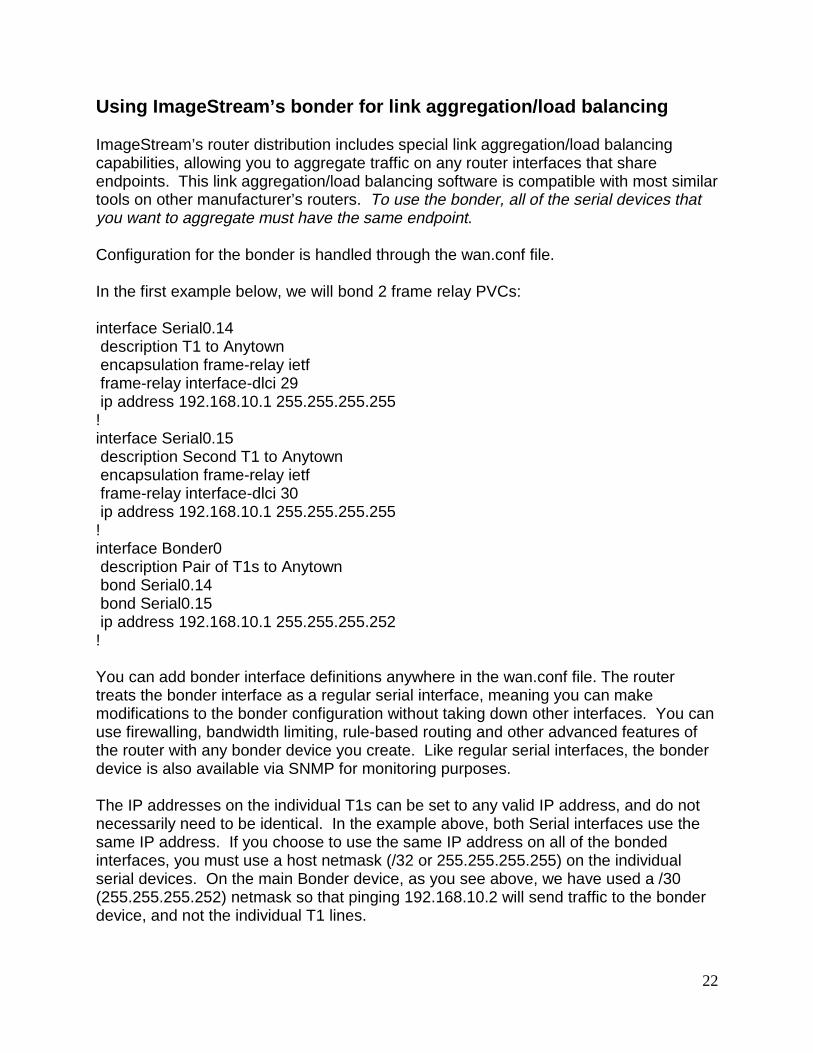
Using ImageStream’s bonder for link aggregation/load balancing
ImageStream’s router distribution includes special link aggregation/load balancingcapabilities, allowing you to aggregate traffic on any router interfaces that shareendpoints. This link aggregation/load balancing software is compatible with most similartools on other manufacturer’s routers. To use the bonder, all of the serial devices thatyou want to aggregate must have the same endpoint.
Configuration for the bonder is handled through the wan.conf file.
In the first example below, we will bond 2 frame relay PVCs:
interface Serial0.14 description T1 to Anytown encapsulation frame-relay ietf frame-relay interface-dlci 29 ip address 192.168.10.1 255.255.255.255!interface Serial0.15 description Second T1 to Anytown encapsulation frame-relay ietf frame-relay interface-dlci 30 ip address 192.168.10.1 255.255.255.255!interface Bonder0 description Pair of T1s to Anytown bond Serial0.14 bond Serial0.15 ip address 192.168.10.1 255.255.255.252!
You can add bonder interface definitions anywhere in the wan.conf file. The routertreats the bonder interface as a regular serial interface, meaning you can makemodifications to the bonder configuration without taking down other interfaces. You canuse firewalling, bandwidth limiting, rule-based routing and other advanced features ofthe router with any bonder device you create. Like regular serial interfaces, the bonderdevice is also available via SNMP for monitoring purposes.
The IP addresses on the individual T1s can be set to any valid IP address, and do notnecessarily need to be identical. In the example above, both Serial interfaces use thesame IP address. If you choose to use the same IP address on all of the bondedinterfaces, you must use a host netmask (/32 or 255.255.255.255) on the individualserial devices. On the main Bonder device, as you see above, we have used a /30(255.255.255.252) netmask so that pinging 192.168.10.2 will send traffic to the bonderdevice, and not the individual T1 lines.

23
Below is another example configuration for bonded links:
interface Bonder0 description Chicopee POP bond Serial16 bond Serial17 ip address 216.20.6.13 255.255.255.252!
In this example, we’ve chosen to leave the individual serial device configurations withtheir own netblocks.
interface Serial16encapsulation hdlcdescription Chicopee CC T1-1ip address 216.20.6.6 255.255.255.252!interface Serial17encapsulation hdlcdescription Chicopee CC T1-2ip address 216.20.6.10 255.255.255.252!
Bonder can be used with any type of serial device, regardless of the interface speedsattached to it. The bonder software will automatically balance traffic to favor any higherspeed links in the list of bonded devices. Bonder distributes the load evenly based oneach interface’s bandwidth and the number of packets currently queued to thatparticular device. For example, a DS-3 link bonded with a T1 line will send more trafficto the DS-3 and will efficiently use the available bandwidth on both interfaces. Bonderautomatically calculates bandwidth based on the active (hardware and protocol are both“up”) bonded interfaces and will not attempt to use any interface which has hardware orprotocol down.

24
V. Troubleshooting
Here are some of the more commonly encountered problems with ImageStream routersand Linux driver Installation:
Q: I have verified my configurations in wan.conf, but hardware and protocol are stillshowing “down” in the stats output. How can I find out if the card is sending data, orreceiving protocol data from the network?
A: Each serial interface in wan.conf supports “debug” statements with varying levels ofverbosity. To receive hardware-related messages, use “debug hardware X” where X isthe debug level you choose. To receive protocol-related messages, use “debugsoftware X” where X is the debug level you choose. The messages will appear on therouter console, in the router debug log option from the router menu, and in the output ofthe kernel messaging file (available by typing “dmesg” at the command line).
Valid debug levels:
1 Module information only.2 Adds hardware details.3 Adds port state changes.4 Adds port error details.5 Adds advanced hardware details.6 Adds tx & rx packet counts.7 Adds lock debugging.8 Adds function entry/exit debugging.9 Turns on everything possible.
Q: I can see that the module has been inserted into the kernel, but the ifconfigcommand isn't showing the interface. What did I do wrong?
A: Ensure that the parameters set your wan.conf file are valid. If you have not set anencapsulation in the wan.conf file, the interface may not appear in ifconfig. Ensure thatyou have removed any “shutdown” statements from serial ports you want to use.
If you are using PPP, make sure that the line that you are connecting to hassuccessfully negotiated a connection. Unlike Cisco HDLC, Raw IP, and Frame Relay,PPP will not show a device in ifconfig until a link has been negotiated. Check the statsprogram (available by running “stats” from the command line or from the menu system)to ensure that your hardware is connected properly.
Q: I’m using frame relay encapsulation and am connecting to a Cisco router on theother side of the link. My configuration appears to be correct, there are no problemswith my telephone company circuit, but stats reports that the protocol down.

25
A: Cisco routers do not support the open IETF frame relay standard by default. In theCisco IOS, you must specifically use “encapsulation frame-relay ietf”. Check theconfiguration on the remote Cisco router. The telephone company will often report thatthe LMI types appear to be mismatched when the Cisco router is configured for Cisco’sproprietary implementation of frame relay.
Q: When I run “up”, I get an error about a kernel version mismatch.
A: Your Linux kernel is configured to require kernel module versions to match theversion of the kernel you are currently running. This option is unnecessary, since veryfew packages (PCMCIA for example) require kernel module versions. Recompile yourkernel and answer no to the question about setting kernel module versions.
Q: I'm trying to make one card talk to another card back-to-back and nothing ishappening.
A: When connecting two WAN cards back to back, one card has to be set for internalclocking, and the other has to be set for external clocking.

26
Q: I have configured PPP correctly, the stats program shows that the hardware is up,but the protocol stays down. I’ve verified that the line is functioning.
A: Try specifying the destination router’s IP address using the pointopoint command. Ifyou line passes through a multiplexer or a Cascade switch or is connected to an olderrouter, your router may not receive the destination router’s IP address.
Q: I can't get my Linux driver to work and the documentation does not address theproblem I'm seeing.
A: Please send email to [email protected]. We will investigate yourproblem as soon as possible.
This driver, release notes and related documentation are constantly evolving, so checkthe FTP site periodically for the latest revisions. Your input and suggestions to improvethis document are appreciated.
Technical Support
Anonymous FTP:
FTP.IMAGESTREAM-IS.COMlogin: anonymous/pub/SDL
World Wide Web:
http://www.imagestream-is.com/
Electronic Mail: [email protected]: (219) 935-8484Fax: (219) 935-8488

27
VI. Appendix A – Product Return Procedures
Equipment returns to ImageStream fall under the category of Factory Repair or ServiceReplacement. These categories and guidelines are explained in the following sections.
Factory Repair
Customers who return equipment to ImageStream for factory repair should contactImageStream for return authorization and instructions. When you call ImageStream,you will be given a Return Material Authorization (RMA) control number. Mark thisnumber clearly on the shipping container for ease of identification and service. TheRMA control number is simply a shipment-control procedure and does not affect theprovisions of a sales or lease agreement. ImageStream will also request that youprovide the following information for each piece of equipment you wish to return:
Name of Product and Description Serial Number Customer Order Number Failure Symptoms
You will be provided a shipping address to return any defective equipment or parts.
Re-packing Guidelines for Equipment Return
Equipment or parts that are being returned to ImageStream for any reason must beproperly packaged to prevent damage in shipment and handling. If the original packingmaterial and shipping container are available, reuse these items to return equipment. Ifthese items are not available, package the equipment for shipment as follows:
Secure movable and exposed parts before shipping so will not become loose inshipment and cause damage or be damaged. Abrasive or dusty materials should notbe used for cushioning. Customers should attempt to ship equipment weighing morethan 20 pounds in sturdy or double-wall containers.
When returning more than one item in the same shipping container, wrap each unitindividually in air-cell or similar material, prevent possibility of movement of individualunits during shipment. Place each printed circuit (PC) card in an individual conductivebag, wrap the card in a double layer air-cell or similar material if possible. Ship in asturdy container that prevents movement of individually wrapped cards.

28
Specific Packing Guidelines
In returning equipment to ImageStream, the alternative packaging guidelines are listedwith the exception of procedures authorized by ImageStream.
Most Desirable
Return the equipment in its original packing material and shipping container.
Acceptable
Wrap the equipment in sufficient air-cell (bubble pack) or similar material providingcushioning, ship in a double-wall container if possible.

29
VII. Appendix B – Netmask Conversion Table
Bitmask(Bits)
Dotted DecimalNetmask
HexadecimalNetmask Binary Netmask
/0 0.0.0.0 0x00000000 00000000 00000000 00000000 00000000/1 128.0.0.0 0x80000000 10000000 00000000 00000000 00000000/2 192.0.0.0 0xc0000000 11000000 00000000 00000000 00000000/3 224.0.0.0 0xe0000000 11100000 00000000 00000000 00000000/4 240.0.0.0 0xf0000000 11110000 00000000 00000000 00000000/5 248.0.0.0 0xf8000000 11111000 00000000 00000000 00000000/6 252.0.0.0 0xfc000000 11111100 00000000 00000000 00000000/7 254.0.0.0 0xfe000000 11111110 00000000 00000000 00000000/8 255.0.0.0 0xff000000 11111111 00000000 00000000 00000000
/9 255.128.0.0 0xff800000 11111111 10000000 00000000 00000000/10 255.192.0.0 0xffc00000 11111111 11000000 00000000 00000000/11 255.224.0.0 0xffe00000 11111111 11100000 00000000 00000000/12 255.240.0.0 0xfff00000 11111111 11110000 00000000 00000000/13 255.248.0.0 0xfff80000 11111111 11111000 00000000 00000000/14 255.252.0.0 0xfffc0000 11111111 11111100 00000000 00000000/15 255.254.0.0 0xfffe0000 11111111 11111110 00000000 00000000/16 255.255.0.0 0xffff0000 11111111 11111111 00000000 00000000
/17 255.255.128.0 0xffff8000 11111111 11111111 10000000 00000000/18 255.255.192.0 0xffffc000 11111111 11111111 11000000 00000000/19 255.255.224.0 0xffffe000 11111111 11111111 11100000 00000000/20 255.255.240.0 0xfffff000 11111111 11111111 11110000 00000000/21 255.255.248.0 0xfffff800 11111111 11111111 11111000 00000000/22 255.255.252.0 0xfffffc00 11111111 11111111 11111100 00000000/23 255.255.254.0 0xfffffe00 11111111 11111111 11111110 00000000/24 255.255.255.0 0xffffff00 11111111 11111111 11111111 00000000
/25 255.255.255.128 0xffffff80 11111111 11111111 11111111 10000000/26 255.255.255.192 0xffffffc0 11111111 11111111 11111111 11000000/27 255.255.255.224 0xffffffe0 11111111 11111111 11111111 11100000/28 255.255.255.240 0xfffffff0 11111111 11111111 11111111 11110000/29 255.255.255.248 0xfffffff8 11111111 11111111 11111111 11111000/30 255.255.255.252 0xfffffffc 11111111 11111111 11111111 11111100/31 255.255.255.254 0xfffffffe 11111111 11111111 11111111 11111110/32 255.255.255.255 0xffffffff 11111111 11111111 11111111 11111111

30
VIII. Appendix C – Cables And Adapters
Several adapter cables currently available for all WAN cards are illustrated in thissection. As additional physical interfaces are added, the necessary adapter cables willbe added to this section.
RS-232 Adapter Cable
The adapter cable required for output to the standard RS232, DB25 connector standardis illustrated in Figure C-1.
Figure C-1 DB26P To DB25P RS232 Adapter CablePart # 400005

31
V.35 Adapter Cable
The cable required for adapting the WANic DB26S connector to a DCE such as aCSU/DSU with a V.35 (Winchester) connector is illustrated in Figure C-2.
Figure C-2, DB26P to V.35 Adapter CablePart # 400006

32
RS-422 Adapter Cable
This adapter cable is required for output to a standard RS-422. The DB25 connector onthe cable is identical to one on the RS-232 described previously. Figure C-3 describesthe RS-422 signaling. The cable required for adapting the WANic DB26S connector tothe RS422 (DB25 connector) standard is illustrated in Figure C-3.
Figure C-3, DB26P to DB25 (RS422) Adapter CablePart # 400020
33
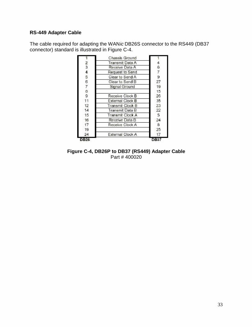
RS-449 Adapter Cable
The cable required for adapting the WANic DB26S connector to the RS449 (DB37connector) standard is illustrated in Figure C-4.
Figure C-4, DB26P to DB37 (RS449) Adapter CablePart # 400020
34
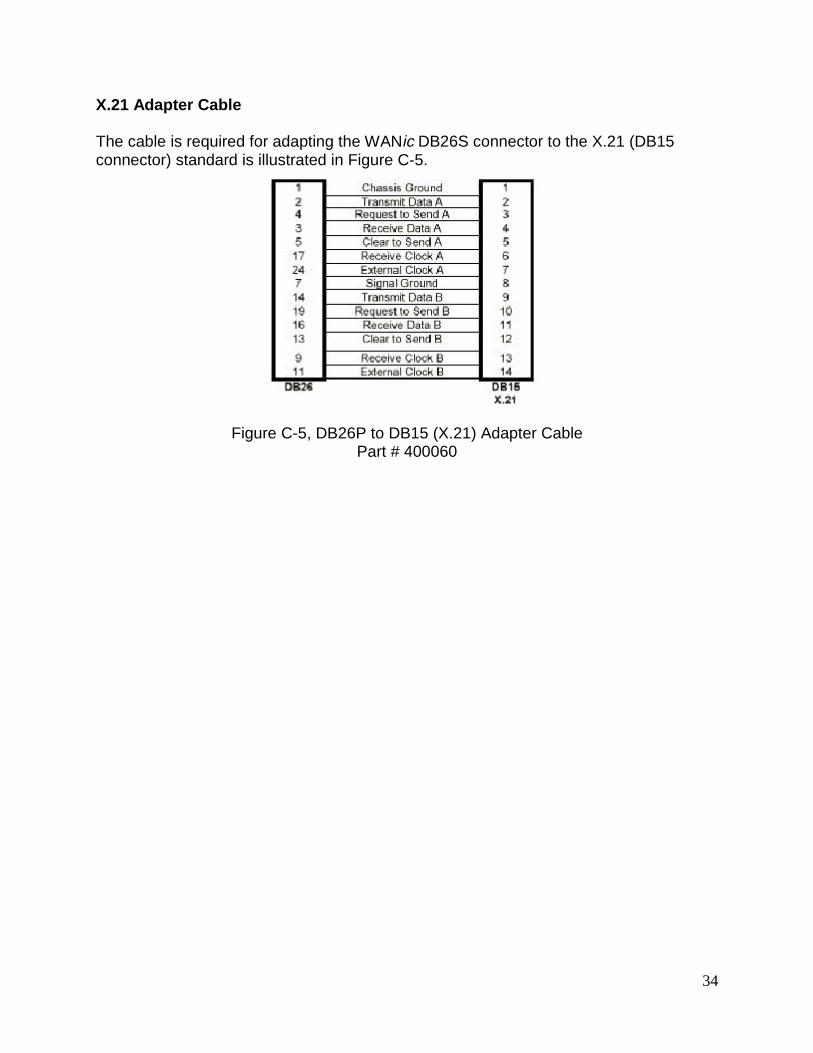
X.21 Adapter Cable
The cable is required for adapting the WANic DB26S connector to the X.21 (DB15connector) standard is illustrated in Figure C-5.
Figure C-5, DB26P to DB15 (X.21) Adapter CablePart # 400060
35
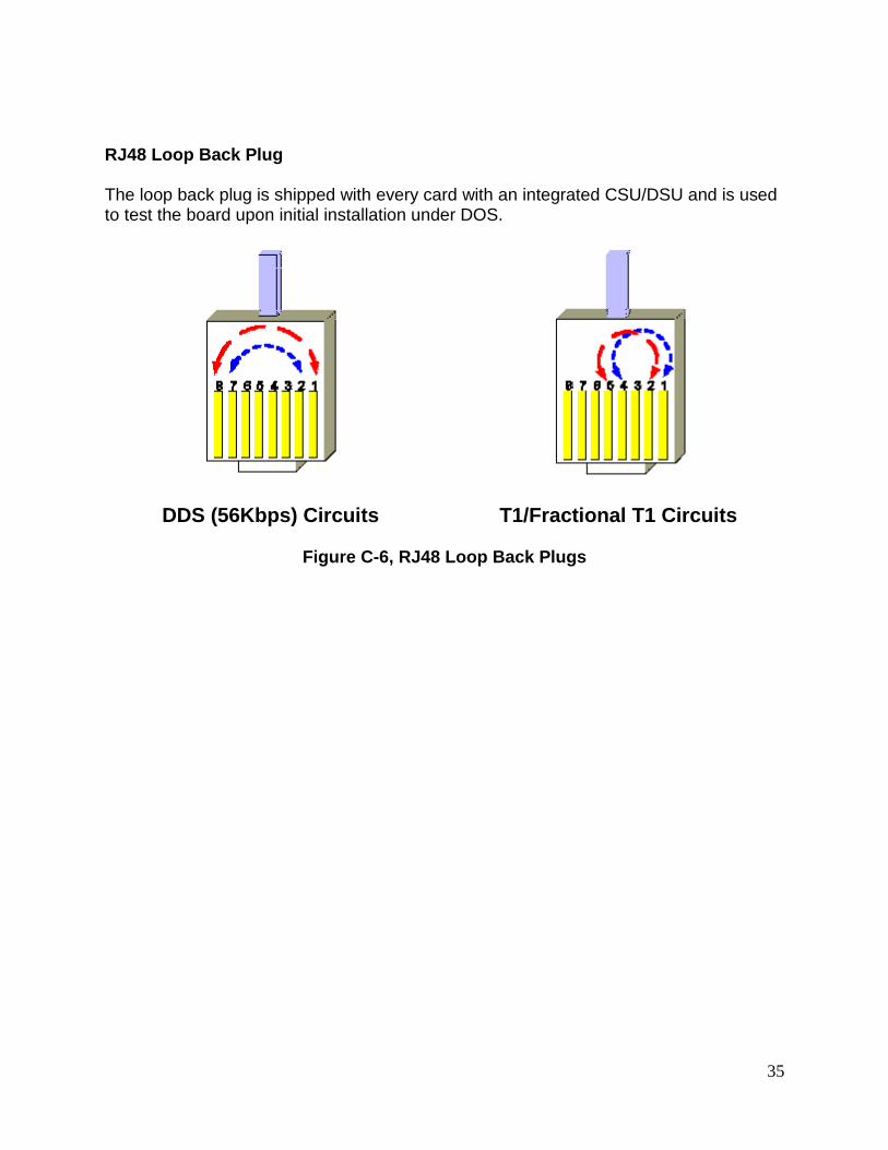
RJ48 Loop Back Plug
The loop back plug is shipped with every card with an integrated CSU/DSU and is usedto test the board upon initial installation under DOS.
DDS (56Kbps) Circuits T1/Fractional T1 Circuits
Figure C-6, RJ48 Loop Back Plugs

36
RJ48C to RJ48C Crossover (Loopback) Cable
The Crossover (Loopback) Cable is a RJ48C to RJ48C cable, optionally supplied. Thecrossover cable is used to connect two CSU/DSUs together.
Figure C-8a, RJ48C to RJ48C DDS Crossover (Loopback) Adapter CableT1 and Fractional T1 Circuits Only
Figure C-8b, RJ48C to RJ48C DDS Crossover (Loopback) Adapter CableDDS (56Kbps) Circuits Only

37
DB26 to DB26 Crossover (Loopback) Cable
The Crossover (Loopback) Cable is a DB26 to DB26 cable, optionally supplied. Thecrossover cable is used to connect two non-integrated CSU/DSU cards together. FigureC-9 displays the pin connections for the Crossover (Loopback) Cable.
Figure C-7, DB26 to DB26 Crossover (Loopback) CablePart # 400018
38
IX. Appendix D – T1 Basics
What Is A T1 Line?
A T1 line is a digital transmission line capable of 1.544 Million bits per second (Mbps).T1 normally carries 24 voice or data channels. Each channel has a sample rate of 8kHzwith a resolution of 8 bits of data per sample. Every 192 bits of the transmission aframing bit is added.
24 Voice/Data Channels8 kHz Sample Rate8 Bits per Sample1 Framing Bit per 192 Data bits
24 Channels x 8 Data Bits + 1 Framing Bit = 193 Bits per Frame193 Bits per Frame x 8,000 Frames per Second = 1,544,000 Total Bits per Second
How Can A T1 Be Used?
T1s can be used to connect two distant PBX’s together to form a single functioningPBX’s. T1s are also used to form a bridge between two Local Area Networks (LAN’s).In this way one single Wide Area Network (WAN) is formed. A single T1 line can beused for both PBX’s and digital data at the same time by dedicating channels to eachtask. Other variations of service include fractional T1. Fractional T1 is a reducednumber of channels leased from the service provider. The transmission rates vary from56Kbps to 1.544Mbps.
What is a CSU/DSU?
A Channel Service Unit (CSU) also called a Data Service Unit (DSU) is a device used toterminate a digital service on the customers end. The CSU/DSU maintains records ondifferent types of line errors and provides functions for line conditioning, lineequalization, and loopback modes. These functions can be accessed from the mainoffice of the service provider to maintain line quality.
CSU/DSU Alarms
A CSU/DSU reports different types of alarms to indicate the status of the T1 line. Thesealarms allow the user to know if line problems are occurring. Some of these alarms aredescribed below:
Loss of Signal – activated when insufficient signal pulses are being received.Loss of Frame Sync – activated when frame pulses have not been detected for2 seconds.Loopback Mode – activated when the CSU has responded to either a networkor user loopback request.

39
Yellow Alarm – received from the remote CSU, when it has lost frame sync.
What needs to be configured for a CSU to Work?
The T1 service provider will inform the customer what settings should be set for theirspecific service. The service provider will specify the line build out (LBO= 0, -7.5, -15dB), framing type (D4 or ESF) network line code (B8ZS or AMI), pulse density enforcing(AMI only), and the signaling mode (ATT54016 or ANSI T1.403) that the customersCSU should be configured for. For a fractional T1, the service provider must alsospecify the active channels (DS0s).
AMI versus B8ZS Line Coding
When using AMI (alternate mark inversion) mode with non-inverted data, a problemarises when a series of zeros is sent across the transmission line. These zeros preventthe receiver, who relies on clock edges for sync, from establishing a proper sync. Thereare two ways to correct this problem.
1. AMI Mode with Inverted HDLC Data
If the network (external CSU, carrier, etc.) can AMI mode with inverted HDLC data, theN2csu can be placed in INVERT HDLC DATA mode. With data inversion enabled,proper ones density will be maintained on the line.
2. B8ZS Mode (If Available)
B8ZS (bipolar with 8-zero substitution) mode was designed to correct for AMI's pulsedensity problem. B8ZS inserts BPVs at specific points in the data to allow the receiverto maintain sync. At the receiving end, any B8ZS BPV patterns are recognized and thecorrect data patterns are re-constructed.