the iccml as a novel teaching tool to improve undergraduate education and student ... · ·...
TRANSCRIPT

The ICCML as a novel teaching tool
to improve undergraduate education and student learning of civil engineering
FINAL TECHNICAL REPORT Project A481
Dates covered: October 1, 2003 to September 30, 2004
Prepared for:
Infrastructure Technology Institute Northwestern University
1801 Maple Avenue Evanston, IL 60201-3140
prepared by:
Roberta Massabò Associate Professor of Structural Mechanics
Department of Civil, Environmental and Architectural Engineering University of Genova
Italy Email address: [email protected]
March 2008

1
DISCLAIMER The contents of this report reflect the views of the authors, who are responsible for the facts and accuracy of the information presented herein. This Document is disseminated under the sponsorship of the Department of Transportation University of Transportation Centers Program, in the interest of information exchange. The U.S. Government assumes no liability for the contents or use thereof.

2
0. Table of Contents
0. Table of Contents 1
1. Summary 2
2. Technical Report 3
3. Appendix 5

3
1. Summary
The project, started in June 2002 and ended in September 2004, aimed at investigating the feasibility of using the Infrastructure Construction and Condition Monitoring Laboratory (ICCML) of the Infrastructure Technology Institute (ITI), its web-site and remotely operated web-cameras as a novel teaching tool to improve undergraduate education and student learning of civil engineering.
Teaching material (courseware) has been developed using the case study method and new technologies. The courseware is incorporated into a highly structured and expandable web site (http://www.iti.northwestern.edu/iccml_site) and deals with an in-depth analysis and presentation of the 11th Street Pedestrian Bridge, a project of the City of Chicago (under construction at the south-west end of Grant Park in the years 2003-04). Real time view of the construction operations was made possible through a remotely operated web camera overlooking the construction site.
The main educational goal of the project is to bring knowledge from the infrastructure/building industry to university curricula. The web site allowed active monitoring of construction sites that would otherwise be restricted and incorporates information on the history of the projects, construction plans, design drawings, calculations and other material that would otherwise be confidential and restricted to the design team and contractors. The courseware is intended to be a tool to synthesize and apply knowledge acquired in different undergraduate civil engineering courses through interactive activities, quizzes and open-ended problems.
The project has been executed by a graduate student, Randy Herbstman (graduated in June 2004), under the supervision of the P.I.. Brian Nielsen, manager of Learning Support Systems, and Jonathan Smith, Distributed Learning Architect, of the Academic Technologies Department of Northwestern University guided the team in the design and development of the web site, navigational paths and interactive activities.

4
2. Technical Report BACKGROUND AND PROJECT OBJECTIVES The main educational goal of the project was to bring knowledge from the infrastructure / building
industry to university curricula. This was done through the development of multimedia supported case-
study material for undergraduate civil engineering courses. The courseware has been incorporated into
a highly structured and expandable web site.
Activities preliminary to the development of the courseware have been the following:
- bibliographical investigation on the use of the case study method, new media and new technologies in
teaching at high level institutions; bibliographical investigation of prior experiences in educational
projects based on the use of new technologies in teaching;
- analysis of two civil engineering projects, the Hoover Dam Bypass (Arizona/Nevada border) and the
11th Street Pedestrian Bridge (Chicago, IL), that have been selected as possible case studies; final
selection of the 11th Street Pedestrian Bridge project in Chicago as exemplary case study;
The main objectives of the project were the following:
1) design and development of the web site that contains the courseware with progressive incorporation
of teaching material;
2) Design and development of a navigational path for effective learning that includes a set of
interactive activities (level of education: undergraduate civil engineering).
3) Design and development of the basic structure of navigational paths for different levels of education.
The program has been executed at the Department of Civil and Environmental Engineering of
Northwestern University and a graduate student has been supported to work on the project. Significant
has been the collaboration with the Academic Technologies Department of Northwestern University
(Jonathan Smith and Brian Nielsen).

5
APPROACH AND RESULTS
The web site and the courseware have been the primary deliverables of the project (http://www.iti.northwestern.edu/iccml_site). A final report in the form of a MS thesis has also been delivered and is attached to this report. The thesis describes the structure of the website, the case study examined and some of the interacting teaching/learning tools that have been developed. The main features of the courseware are: - the civil engineering project is presented as a case history; - the material is organized in a hierarchical structure with an expandable modular approach integrating basic media: text, graphics, video, simple animation; - a highly structured package is generated for effective learning, allowing for individual item viewing (to support specific classes and lectures) and sequential learning (to proceed chronologically through the project) and avoiding the possibility of loosing track of the navigational path; - information is organized into small units and additional printable documentation from books, original documents, plans, etc. is included, along with links and references, to allow further study and investigation; - a limited level of interactivity is included through interactive problem solving, electronic quizzes, open ended problems; - usage outside of classroom (e.g. homework) is allowed and properly organized to give students the time to think and understand.

6
3. Appendix
MS Thesis, Northwestern University, 2004. Candidate: R. Herbstman

NORTHWESTERN UNIVERSITY
The Infrastructure Construction and Condition Monitoring Laboratory (ICCML) as a Novel Teaching
Tool to Improve Undergraduate Education in Civil Engineering
A Thesis
Submitted to the Graduate School In Partial Fulfillment of the Requirements For the Degree
MASTER OF SCIENCE Field of Civil Engineering
By Randall M. Herbstman
EVANSTON, IL June 2004
ii
Summary
This thesis describes the creation of a set of web-based learning/teaching tools for civil
engineering education. A modular expandable website was created to describe
construction projects as case studies and to provide interactive teaching material based on
those projects. The homepage of the website for this project is available online at
http://www.iti.northwestern.edu/iccml_site.
An example section of the website was produced based on the design and
construction of the 11th Street Pedestrian Bridge and Columbus Drive Underpass in
Chicago, IL. The project is presented as a case study history and includes a description
of the project site and detailed information and media about the design and construction
of the bridge and underpass. This website also includes a webcamera overlooking the
construction site that was utilized to allow virtual access to the site and to create still
images and time lapse movies of the project.
Interactive teaching tools based on the design of the precast, prestressed concrete
beams of the bridge were created. This interactive material takes the students through all
steps of the design and makes them calculate and verify the safety of these structural
components. It uses a series of modules that contain text background information,
images of the construction site, the construction process and the structural components,
design drawings and animations. This integrated material gives the student direct and
easy access to all information relevant to the project.
The case study and the interactive teaching tools were designed to supplement
traditional classroom teaching by providing real world examples that can be used for
classroom discussions on problem solving and decision making. Both parts of the
website are intended to be prototype teaching material to prove the usefulness of this
approach, by exploring the advantages of using multimedia material, such as
webcameras, still images and movies and interactive activities, in teaching civil
engineering.

iii
Acknowledgements
I would like to thank the following people for their assistance with the completion of this
project. I would like to thank my advisor, Professor Massabo, for her continued guidance
and support during the completion of the online material and this thesis. I would also like
to thank the other members of my committee Professor Edwin Rossow, Professor Pablo
Durango-Cohen and Proffessor David Schulz for their assistance with this project and
their educational guidance here at Northwestern.
I would like to thank the following members of the Infrastructure Technology
Institute for lending their expertise to the technical aspects of the project: Dan Marron
for installing and maintaining the webcamera as well as fixing the frequent problems that
arose during its installation. Ruth Allee for providing the server space for the website
and maintaining my data.
I would like to thank Jonathan Smith, Distributed Learning Architect, from the
Academic Technologies Department for teaching me about the creation of webpages and
using Flash as an educational tool.
Lastly, I would like to thank Georgia Borovillos, Krishna Sandepudi and the rest
of the people involved with the design of the 11th Street Pedestrian Bridge for providing
me with a wealth of information about the design of the bridge and for answering my
questions about how the design was computed.
iv
Table of Contents
Summary ............................................................................................................................. ii
Acknowledgements............................................................................................................ iii
Table of Contents............................................................................................................... iv
Table of Figures .................................................................................................................. v
2. Introduction..................................................................................................................... 1
2.1 Purpose...................................................................................................................... 1
2.2 Goals ......................................................................................................................... 2
3 Case-Study Website ......................................................................................................... 8
3.1 Outline of the Website Features and Prototype Project ............................................ 8
3.2 Prototype Case Study: The 11th Street Pedestrian Bridge ...................................... 12
4. Interactive Teaching Tools ........................................................................................... 16
4.1 Features of the Interactive Teaching Tools............................................................. 16
4.2 Teaching/Learning Objectives ................................................................................ 18
4.3 Example Design Module ........................................................................................ 25
5 Conclusions and Future Work ....................................................................................... 33
5.1 Conclusions............................................................................................................. 33
5.2 Future Work............................................................................................................ 34
6. References..................................................................................................................... 36
Appendix 1.1: Site Map of Case Study Website............................................................... 37
Appendix 1.2: Site Map of Interactive Teaching Tools.................................................... 38
Appendix 2: Software and Technical Concerns................................................................ 39
v
Table of Figures
Figure 1 Rendering of the 11th Street Pedestrian Bridge ................................................... 3
Figure 2 Image captured from the webcamera of the construction of the bridge
superstructure on July 18, 2003 .................................................................................. 6
Figure 3 CIVCAL Website Homepage............................................................................... 8
Figure 4 Homepage of the Case Study Website showing both the horizontal tabs and
buttons down the left-hand side. ............................................................................... 10
Figure 5 Introduction page for the 11th Street Bridge section of the website illustrating
one of the popup menus. ........................................................................................... 11
Figure 6: Layout of Grant Park after Redevelopment ...................................................... 13
Figure 7: Photo of the Completed 11th Street Pedestrian Bridge..................................... 14
Figure 8 Installation of the precast bridge beams on July 8, 2003 ................................... 15
Figure 9 Introduction page for the Interactive Teaching Tools. ....................................... 17
Figure 10: Load Effect Combinations Activity ................................................................ 27
Figure 11: Service Load Design at Initial Stage Activity ................................................. 29
Figure 12: Service Load Design at Final Stage Activity .................................................. 30
Figure 13: Ultimate Strength Design Activity .................................................................. 31
Figure 10: Site Map of Case Study Website..................................................................... 37
Figure 11: Site Map of Interactive Teaching Tools .......................................................... 38
vi

1
2. Introduction
2.1 Purpose
Civil Engineering is a hands-on discipline that requires students who are engaged in its
study to be able to apply concepts in a variety of situations. Undergraduate classroom
time is very often focused on the underlying theories to the determent of presenting real-
world examples. When the students graduate and find employment in this field they will
be required to apply their theoretical knowledge to actual situations and projects. The
aspiration in completing this project is to provide a method to deliver real-world
engineering using web-based technology that students should already be familiar with.
This project hopes to aid students in their understanding of and applying the various types
of information presented to them during their coursework. It also hopes to aid the
professors and teachers in presenting their material in an interesting, attention gathering
and efficient manner.
For student users, we hope to provide a simulated hands-on experience by
presenting the case study of a real civil engineering project with supporting multimedia
and interactive teaching tools. This construction project contains aspects from multiple
areas of civil engineering and applies knowledge from a variety of undergraduate
courses. The use of real world case studies in addition to traditional classroom activities
greatly increases the student’s comprehension of the material. It provides the student
with more than just the traditional lecture format where the primary focus is on specific
design issues. The use of case based teaching provides a context for the classroom
theories in the “real world” concerns of actual engineering professionals (Angelides et al.
2000). The civil engineering project that will be the basis for this project’s case study is
the source for a set of interactive teaching/learning activities. The interactive section
shows the students how their accumulated knowledge can be used once they reach the
level of professional practice. This is done by making them go through the actual design
and review of some of the structural components of the bridge following the design and
decision making process of the engineers who worked on the actual project.
For teachers, we wish to facilitate their classroom activities through presenting
them with already developed online course material. The material that has been
developed is intended to supplement an undergraduate, most likely senior-level, course in
2
structural design. The material created in this project can be used as solo examples for
classroom lectures to illustrate design theories or to form the basis of an entire section of
a course in which the case study of the 11th Street Pedestrian Bridge is chronicled. By
using this material provided over the Internet, we can reduce some of the classroom time
needed to present examples and remove some of the preparation time needed to organize
examples to be presented in class.
The material is presented in the website as a case history, meaning that the design
approach of the actual designers of the bridge is presented, discussed and applied in
different interactive activities. The material however, is also intended to be used as the
starting point for classroom discussions on the design choices and the application of the
design theories. Alternate methods of construction or theories of design could be
compared and evaluated against what was done for this bridge.
2.2 Goals
The aim of the project is to produce a set of web-based teaching/learning tools for civil
engineering education. This is done by creating a website that presents case studies,
essentially in the form of case histories, of various civil engineering projects and creating
a set of interactive teaching/learning activities based on the presented civil engineering
projects that take the student through one specific aspect of the design or construction of
the project.
The case study of the 11th Street Pedestrian Bridge and Columbus Drive
Underpass is the project that as been used an exemplary case to present the basic ideas of
the work. The teaching/learning interactive activities take the student through the design
of the precast, prestressed concrete beams of the bridge.

3
Figure 1 Rendering of the 11th Street Pedestrian Bridge
The material we have developed is intended as a proof of concept to illustrate and
highlight the potential of web-enhanced case study based teaching for civil engineering.
By proving that this idea is a useful and practical method to supplement more traditional
educational delivery, the hope is that other members of the civil engineering teaching
community would become interested in the project and lend their expertise to later
incarnations of the project. All the aspects of the website are intended to be modular so
that each section can be developed independently and yet individually still represent a
complete set of teaching material. The overall structure and framework of the website is
designed to be expandable so that adding on additional case studies or interactive
activities can be done with ease once they have been developed.
Case Study Website The main part of the website will contain multiple projects, including the 11th Street
Pedestrian Bridge and Columbus Drive Underpass. It is intended to become a database
for case studies of interesting civil engineering projects. The goal is to create a modular
site to allow for easy expansion from the original set of construction projects to any
number of cases. The overall design of the website is such that all available information
about the construction projects are easy to locate and use. Each project presented on the
site will be multi-disciplinary so that the case study can be used as supplement material in
4
a variety of civil engineering courses. The inclusion of various subjects in the different
projects also allows the use of the different disciplines in different projects to be easily
compared to examine how different project teams solve the same issues.
The material presented on the website for the 11th Street Pedestrian Bridge and
Columbus Drive Underpass is an example to illustrate how to produce case studies that
will be included on the website. By producing an effective and useful case study for the
11th Street Pedestrian Bridge we hope to be able to illustrate the viability of such a
teaching/learning method. The successful representation of this project as a case study
will also provide a catalyst for expanding the scope of the current website and related
materials to other interesting projects.
Interactive Teaching Tools The goal of the interactive teaching tools is to precisely guide the student through a
critical component of the project. These tools will primarily be web-based computer
programs programmed in Macromedia Flash® and be accessible from a link contained in
the main part of the website. The teaching tool developed for the 11th Street Pedestrian
Bridge deals with the actual design and review of some of the structural components of
the bridge. Proceeding along the presented design process, the student will recall the
basic theory needed to understand the steps of the design process. Each interactive
activity will focus on one aspect of the overall design. In most cases the activity will be
broken up into smaller units. Each of these units, modules or “atoms” of knowledge, will
attempt to present once particular concept to the student or guide the user through one
specific task of the overall design. The units are short enough to be accomplished or
completed in a reasonably short amount of time to retain the student’s attention (Wiezel
1998). While each teaching tool is self-contained and presents all of the relevant
background knowledge needed to complete the activities it contains, it should not be
taken as the soul source of learning for the student. “The best use of multimedia
applications is repetition. With all of its “bells and whistles,” multimedia applications
can capture the attentions of the student for a longer time period than any other medium,
thus reinforcing the retention of information.” (Wiezel 1998) The use of the interactive
activities along with the case study presented on the website should be used as a
supplement to the classroom to reinforce the theories presented, to encourage the

5
students’ desire to obtain more in depth knowledge and to start discussions on different
possible solutions and applications of the theory concepts.
The interactive teaching tools of the website focus on the design on the precast,
prestressed concrete beams. The goal in using this topic was to provide a part of the
design that was both interesting and challenging to the student. The design of the
prestressed concrete beams allows for discussions relating to the general concept of
design theories, the basic theory of prestressed concrete, modeling of the bridge
components and utilizing design specifications and codes for bridge design. Other
aspects of the bridge design could be detailed in other subsequent interactive tools from
other areas of expertise from civil engineering.
Multimedia and Webcamera Usage Along with proving these educational concepts to be effective and creating these
prototype activities, we hope to demonstrate the usefulness of a live webcamera to the
project. The ability to stream live images across the web in real time is a technology that
is now being embraced in the professional world of civil engineering. Construction and
engineering firms are using cameras to help monitor construction projects and track their
progress. The educational value of such technology has not yet been fully explored. We
hope to find a place for such a device in the educational process of civil engineering and
specifically for the use of a camera overlooking the 11th Street Pedestrian Bridge
construction site
6
Figure 2 Image captured from the webcamera of the construction of the bridge superstructure on July 18, 2003
By proving the usefulness of the webcamera and its associated multimedia
products on this project, future case studies of other civil engineering projects can be
enhanced by monitoring the construction in the same fashion. The images and video
generated from the camera will be integrated into the framework of the web site.
While there is no substitute for structural engineering and civil engineering
students visiting real construction sites, providing a virtual visit through the use of
multimedia technologies can be extremely valuable. A series of websites were developed
by four Hong Kong Universities to provide these virtual construction sites
(http://civcal.media.hku.hk). They all extensively use multimedia technology in a variety
of methods to provide a useful learning environment for civil engineering students. The
Virtual Building and Construction Environment developed by The City University of
Hong Kong uses this principle to provide a method for delivering information about the
design and construction process for medium to high-rise buildings in Hong Kong.

7
Through the use of various multimedia sources, the case studies and interactive activities
will obtain enhanced educational value by immersing the student more fully into the life
cycle of the construction projects (Barrett and Wilkins 2000). The case studies presented
on the website for this project attempt to achieve a similar amount of integration of
multimedia.
Each civil engineering project as part of the main website will also make use of
electronic versions of available design drawings, construction documents, photos of the
construction site and webcamera videos to completely involve the student in all aspects
of the project. New technologies and computer software allow web-designers to create
and edit visual media with professional results without significant training. Photographs
of the actual construction of structural elements can be altered to make a concept of the
design more clear. A webcamera of the construction site can be used to create a time-
lapse movie of the construction of the project. This type of movie can illustrate how the
various elements of the design are combined to form the entire structure. The teaching
tools will make use of original static and interactive graphics, diagrams and forms to
form the basis of what the students will see when they access one interactive module.
The interactive teaching tools will also make use of the design drawings to illustrate the
design and to provide visual representations for the calculations that are a part of the
design process.
8
3 Case-Study Website
3.1 Outline of the Website Features and Prototype Project
In order to present useful and accessible information, the website has been developed
following a similar model to what was developed by the University of Hong Kong for the
CIVCAL (Civil Engineering Computer Aided Learning) website
(http://civcal.media.hku.hk). This part of the CIVCAL website provides a database of
civil engineering projects in both China and Hong Kong. This is a very successful
project created to aid the teaching of civil engineering by providing a source for
multimedia case studies. The information on the University of Hong Kong section of the
site is cross-referenced by project and by discipline and the layout of the main page
reflects this as shown in Figure 3. Here all of the features of the organization of this site
are shown. The user can access the information by project and learn about the design and
construction of that specific project or by choosing a specific discipline. By selecting a
discipline the user is then presented with all the information related to that subject area
available on the website and given access all of those pages.
Figure 3 CIVCAL Website Homepage

9
The main page of the website has been organized to provide a similar type of
organization so that the user will have direct access to the different civil engineering
projects and the different disciplines.
The homepage of the project website has two sets of links. Across the top of the
page just under the title there are tabs linking the user to each construction project.
Clicking on these tabs will bring the user to the main page of the project. The users
should start with this page and proceed through all of the available information is they
wish to learn about one specific project. Down the left side, there are buttons for subject
areas or disciplines that are covered by the construction projects. Each of these buttons
will bring the user to a page where links are provided to the sections of each project
where that subject area is applied. This part of the website is still under development. It
will be organized in a way similar to that of the CIVCAL site.
The overall organization of the case study website can be seen from the homepage
of the site in Figure 4. The division of the subject areas is as follows: Structural
Engineering and Mechanics, Environmental Engineering, Geotechnical Engineering,
Construction/Project Management, Transportation Engineering and Project
Documentation.
10
Figure 4 Homepage of the Case Study Website showing both the horizontal tabs and buttons down the left-hand side.
The prototype module developed for the website is based upon the 11th Street
Pedestrian Bridge and Columbus Drive Underpass City of Chicago Project. The case
study presents the important information about the design and construction process of the
bridge. The major topics of this part of the website are accessible down the left side of
the page. These topics are: Introduction and History, Project Site, Major Structure
Selection, Project Design, Project Construction, Project Management, Webcam, Teaching
Tools and Current Progress. The first seven topics present information about the project
gathered from conversations with the members of the design team, official project
documentation, construction drawings and visits to the project site. They are subdivided
into more specific areas that can be accessed from a menu that pops up when the mouse

11
rolls over each button. Under the Project Design topic, for instance, the subdivisions are
Design Introduction, Bridge, Underpass and Foundations (See Figure 5).
Figure 5 Introduction page for the 11th Street Bridge section of the website illustrating one of the popup menus.
The Webcam button provides access to the time-lapse movies that were created
from the webcamera over the course of the project’s construction. During construction,
when the webcamera was active, this page also provided a link to a current image of the
construction site. The Teaching Tools button gives access to the interactive teaching tools
created based upon this project. The last button, “Current Progress,” shows a
photographic progress report of the construction of the project. These photos were taken
from the project site and are more detailed than the webcamera images.
12
Preliminary information was collected about two other projects: the Ford Motor
Company Engineering Design Center at Northwestern University and the Hoover Dam
Bypass Bridge. The 11th Street Bridge project was chosen to become the example
construction project for easy of access to the design and construction information and the
timetable of the project, which best coincided with the schedule of the program. The
information about these two projects could be expanded to fully illustrate them as case
studies for the website.
The material presented in case study portion of the website focuses on the content
of the project rather than focusing on how specific courses will use the information. It
follows the design process of the project rather than discussing the specific subject
related issues. This material can be combined with classroom activities in a variety of
civil engineering courses because it is not course specific. It also provides a good
framework to attach other cases at a later time. This comes from the modular
organization of the site. Both of these features of the site follow recommendations for
providing a useful teaching supplement described both by Chinowsky (1997) and Barrett
and Wilkins (2000).
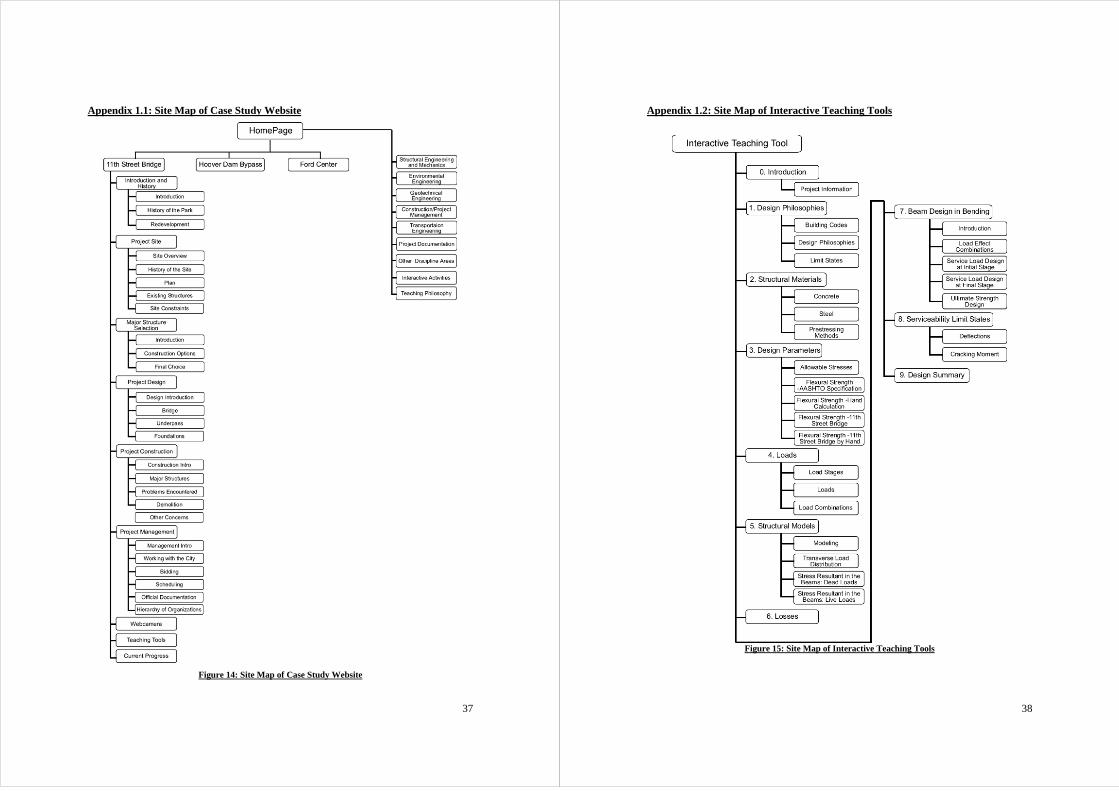
3.2 Prototype Case Study: The 11th Street Pedestrian Bridge
The example case study of the 11th Street Pedestrian Bridge is presented on the website.
The full outline and organization of this portion of the site can be seen in Appendix 1.1.
Described here is a summary of the material available on the website to provide the basic
ideas of the construction project.
The construction of the 11th Street Pedestrian Bridge and Columbus Drive
Underpass are a part of a larger project to redevelop and improve the Grant Park on
Chicago’s Lakeshore. This redevelopment and improvement takes place in concert with
the addition of Millennium Park to the north, which includes a new Frank Gerhy
designed band shell, and the rehabilitation of Soldier Field to the South. The predicted
new look of Grant Park is shown in Figure 6. A detailed history of the park and its
redevelopment can be found under the Introduction and History button shown in Figure
5.

13
Figure 6: Layout of Grant Park after Redevelopment
The new prestressed concrete pedestrian bridge replaces an existing steel beam
bridge with a concrete deck. Because of the age of this bridge and because it was in such
a state of disrepair, rehabilitation of the existing bridge was no longer a viable option.
The bridge spans the existing Metra railroad tracks located in a trench below grade. The
scope of this construction project includes removal and widening of the pedestrian
section of Columbus Drive between Balbo and Roosevelt Road, building a pedestrian
underpass beneath Columbus Drive to provide easier access to the museum campus and
Soldier Field on the lake, removal of the existing pedestrian bridge spanning the train
tracks and building the new pedestrian bridge a short distance to the north. The complete
project site is discussed under the Project Site heading shown in Figure 5.
The structural design for the project involved the design of the bridge piers and
superstructure along with the design of the underpass precast elements. This is explained
in more detail under the Project Design heading. The selection of precast, prestressed
concrete beams to form the basic structure of the bridge was based primarily on cost
effectiveness and the limitations of the site. The bridge is owned by the City of Chicago.
The design was done by H.W. Lochner Inc, an independent design firm. The design of
the precast prestressed concrete beams was performed using a computer program called
14
CONSPAN® developed by Leap Software. The pedestrian bridge utilizes three spans to
cross the railroad tracks. The two outmost supports for the bridge are the reinforced
abutment walls of the trench where the Metra train lines run. The two interior supports
are concrete piers, both set at an angle with respect to the bridge centerline in order to
safely fit in between the train tracks. Each of the three spans of the bridge contains five
precast, prestressed concrete beams. On top of these beams a reinforced concrete deck is
cast in place. This deck does not support an additional wearing surface, so its top surface
is the top of the bridge. The bridge also supports various concrete architectural elements
for the railings and streetlamps. The website describes the various aspects of the design
by showing photographs and copies of some of the construction drawings provided by the
City of Chicago. Pictures of the construction of the bridge can be seen in Figure 1 on
page 3 and Figure 8 on page 15. The completed bridge can be seen below in Figure 7.
Figure 7: Photo of the Completed 11th Street Pedestrian Bridge
The initial bid for construction was made public on November 29, 2002. The
bridge was officially opened on September 20, 2003. At that point all major construction
was completed, however, landscaping work continued after that date. The primary
construction contractor for the project was Walsh Construction Company of Illinois. The
railroad tracks provide a unique problem for the construction of the bridge. The only
available time to install the precast beams was overnight or on the weekends when train
service suspended beneath the bridge and the overhead electric power wires for the train
system could be shut down.

15
Figure 8 Installation of the precast bridge beams on July 8, 2003
16
4. Interactive Teaching Tools
4.1 Features of the Interactive Teaching Tools
The interactive teaching tool created as a prototype activity for this project refers
to the design of the precast, prestressed concrete beams of the 11th Street Pedestrian
Bridge, more specifically the design of span 1 of beam 1 of the bridge. The interactive
teaching tool is made up of 28 individual pages. The pages or modules either provide
guidance in the design process or focus on the calculations necessary for the design of the
beam. Some pages only provide background information to ensure that the student has
enough prerequisite knowledge. The interactive pages also contain background
information, which generally focuses on the specific understanding needed to properly
complete the task.
The organization and structure of the modules is based on the order in which the
tasks should be accomplished to most efficiently complete the design. However, only
users that wish to follow the suggested order and complete the entire design will find this
structure useful. Some users may wish to access individual modules and complete a
specific task instead of the entire design process. Therefore, each page is designed with
content to illustrate where the student is in the design process and to provide access to all
of the other parts of the process. This allows different users trying to use the application
for different purposes to complete their desired task. The importance of presentation on
the effectiveness of this type of teaching material is summarized by J. Carter (2002). The
basic organization of this teaching tool can be seen from the picture in Figure 7, which
shows the introduction to the teaching tools section.

17
Figure 9 Introduction page for the Interactive Teaching Tools.
One of the advantages of using interactive multimedia for teaching purposes is the
instant feedback to the student. This allows the student to better control the learning
process because at all stages they will be informed of what they have done incorrectly
and what was done right. Instant feedback also provides the opportunity to correct any
mistakes and suggest alternate methods of solution to the student. Checking the answers
in each module forces the student to comprehend and apply the lessons of each section
before they can pass to the next area (Cox et al. 1999). Each interactive module contains
a button that checks the student’s progress and evaluates the inputs that have already been
put into the program. If the student has performed a calculation incorrectly or made an
incorrect choice on a design decision, the program informs them of this fact, provides a
possible explanation for the mistake and suggests a change to the calculation in order to
get the correct answer.
18
To proceed through the interactive activities the student assumes the role of the
designer of the beams. The student is responsible for ensuring that a safe design has been
accomplished and all design criteria are met. The design is accomplished by utilizing
both Strength Design and Service Load Design as is specified in the AASHTO Standard
Specifications. The design method illustrated in the interactive activities focuses on the
flexural design of the beams. The design of the beams for shear is not discussed here, it
has been left for future developments to the website. The interactive tool is divided into
ten general topics: Introduction, Design Philosophies, Structural Materials, Design
Parameters, Loads, Structural Models, Losses, Beam Design for Bending, Serviceability
Limit States and Design Summary. Each section is then further subdivided into
individual modules or topics. A site map of the interactive teaching tool modules is
shown in Appendix 1.2.
4.2 Teaching/Learning Objectives
The following section describes the educational aim of each module of the
Teaching Tools section of the web site (See the site map in Appendix 1.2). In the
sections below, the background information contained in each of the modules is briefly
recalled and a brief description of the work to be completed by the student is presented.
In addition, the function of each module in the design process in highlighted.
Introduction and Project Information Page The first page of the teaching tools provides an introduction and a set of
instructions for completing the interactive activities. This page is shown in Figure 7. The
page has a link to the Project Information page, which provides information about the
project. This includes the layout of the bridge and the specific properties of the cross-
section and materials being used. The Project Information page also provides links to
the building codes and specifications that will be used in the teaching tools. The student
must refer back to this page at certain points in the design to retrieve pieces of
information or to reference the codes.

19
Building Codes This module explains which building codes are used to design a pedestrian bridge:
the ACI Building Code Requirements, the AASHTO Standard Specifications for Highway
Bridges and the AASHTO LRFD Bridge Design Specifications. This section also
describes the pedestrian bridge supplement to the AASHTO specifications. A link to
relevant parts of each specification is provided.
Design Philosophies This section describes the basic theory behind the design philosophies used in
both the AASHTO Standard Specifications and the AASHTO LRFD Bridge Design
Specifications. The AASHTO Standard Specifications uses both Allowable Stress Design
and Load Factor Design, while the AASHTO LRFD Bridge Design Specifications uses
only the more modern Load and Resistance Factor Design. The section focuses on the
calculation of the safety factors by the code writers and the specific differences between
the underlying theories of the two different specifications. In the activity of this module
the student is asked to read the AASHTO Standard Specifications, Section 9 (Prestressed
Concrete) and find what design methods are specified by the code to be used in the
design of this prestressed concrete bridge.
Limit States This is a short text only section that describes the limit states, which are an
integral part of the LFD and LRFD design methods. It describes what conditions the
bridge is prevented from reaching by using each limit state in the design and why
preventing these conditions is important. By providing this information the specific
criteria that must be met in the design process are put into the context of an overall design
theory.
Structural Materials and Prestressing Methods This part contains three modules: Steel, Concrete and Prestressing Methods. The
first two describe the mechanical properties of the materials used for prestressed concrete
structures: concrete and steel. The methods for obtaining these material properties are
discussed here. Some material attributes, like the ultimate strength of the prestressing
20
steel, are provided by the manufacturer. Other properties are computed using the
formulas from the AASHTO specifications, e.g. the modulus of rupture.
The Prestressing Method section describes the two most common methods for
prestressing concrete structures, pretensioning and posttensioning. It explains how the
prestressing force is transferred to the concrete, the advantages and disadvantages of each
method and the reasoning for the designers of this project to select precast pretensioned
beams.
Allowable Stresses This section deals with the calculation of the allowable stresses for the Service
Load Design. The background information describes how these stresses will be
calculated and provides a link to a design theory section where the basic theory and
assumptions of the stress analysis are recalled. The activities of this module include:
calculate the initial prestressing force and the allowable concrete compressive and tensile
stresses in the initial stage compute the allowable concrete compressive stresses (for both
precast and cast-in-place concrete) for the different load combinations required by
AASHTO; calculate the concrete tensile stress and cracking stress at the final load stage
for both cast-in-place and precast concrete. The student computes each parameter by
choosing an entry from a table shown in the activity, which is generated from the
allowable stress section of the AASHTO Specifications, and then inputting the correct
nominal stress to determine the allowable stress. The student will have to use the
nominal material properties obtained from the Project Information page.
Flexural Strength The flexural strength is calculated in four different activities. It is done first for
an exemplary rectangular cross-section using both AASHTO formulas and by hand
calculation through an iterative method. Both methods are then applied to the actual
cross-section of the bridge beams. The reason for this repetition is to make sure the
student understands how to calculate the flexural strength of a simple cross section before
the more complex Bulb-T cross-section with the deck cast across the top is considered.
All four sections use the same background information. From the background
and a separate but linked help page, the student will learn the process for computing the

21
flexural strength using both methods. This reference material includes the main
assumptions for the ultimate strength design. It also describes the different stages the
cross-section will go through on the way to failure.
Three equations are provided in the activity from the AASHTO specifications;
one is to compute the stress in the prestressing steel at failure, one to check the ductility
of the cross-section and the final equation uses the stress in the prestressing steel to
compute the ultimate bending moment. The inputs that are required for these equations
can be found by using the specifications and the provided Project Information page. The
result of this module is a flexural strength that will be later compared to the factored
moments on the beam.
The goal of computing the flexural strength by hand using the iterative method is
purely educational. The student goes through the analysis of a prestressed concrete
beam, loaded until failure, to find the ultimate bending moment of the cross-section. By
taking the student through this process the goal we want to illustrate how the AASHTO
equations have been derived and what behaviors will be accounted for by utilizing these
equations. The method used here starts with an initial guess for the stress in the
prestressing steel. The activity then takes the student through incrementally calculating
the strain in the prestressing steel. The final result is compared to a value from an
assumed stress-strain curve corresponding to the initial guess for steel stress. Once a
convergent value for steel stress is found the ultimate bending moment can be computed.
The value for flexural strength obtained here is not used in the design, but it can be
compared and shown to be very close to the strength calculated using the AASHTO code.
Load Stages The manufacturing, installation and use of prestressed concrete beams leads to the
beams passing through various stages of loading. This is a text only section, which
explains the critical load stages (the initial or construction stage, the intermediate or
transportation stage and the final stage) and the different loads that arise in each of them.
The student will have to understand these different load stages when determining and
analyzing the effects of the external loads on the bridge.
22
Loads This section focuses on defining the nominal loads applied to the bridge during its
service life (the self-weight of the beams, the weight of the bridge deck, the weight of the
diaphragms, the additional dead loads on the precast section, the superimposed dead
loads and the pedestrian loads). The background describes the procedure for computing
the nominal load values and the schematic of their application. It also explains the
impact factors for increasing pedestrian load values to account for a dynamic loading.
Some of the load values will need to be further refined in the Transverse Load
Distribution module so that a proper line load value can be used to determine the stress
resultants on the individual beams.
Structural Models The first module of the Structural Models section provides an introduction to
structural modeling. It gives examples on different ways to model a structure and the
types of structural elements a complex structure can be broken into. This section also
describes four example pedestrian bridges and gives a brief description of the structural
model used to design them. At the end of the section, the structural model used for
designing the 11th Street Pedestrian Bridge is described. The goal of this section is to
provide some background knowledge to understand why the 11th Street Bridge is
modeled in the way that is presented in the rest of the design.
Transverse Load Distribution Some of the external loads on the bridge are applied as distributed loads across
the deck surface. These loads must be distributed to each of the supporting beams before
the stress resultants on these beams can be determined. The weight of the bridge deck,
the superimposed dead load and the pedestrian load all need to be distributed in this
section. The background information describes two methods to determine the
distribution factors, the tributary area method and a method that assumes the deck to be a
five span continuous beam. The students should already be familiar enough with
structural design to understand how to use these methods, so the focus here is on the
application of these models to the 11th Street Bridge. In the activity the student will
compare both methods to discover which one controls in the design and then use that
method to compute the actual distribution factors. Lastly, the distribution factors are

23
applied to the bridge loads that must be distributed and the resulting line loads are
determined. By going through the process of computing the distribution factors, the
student will gain a better understanding of the assumptions required to model a bridge in
order to design its various components.
Stress Resultants in the Beams: Dead Loads The goal of this section is to compute bending moments and shear forces in the
precast, prestressed concrete beam due to all of the dead loads acting on the structure.
The structural schematics used to determine the effects of the loads on the structure are
different because the loads are applied at different load stages. Loads applied before the
deck has been cast act on the precast beams alone. The loads applied after the deck has
been cast must be analyzed using a composite cross-section made of the precast and cast-
in-place concrete and are also assumed to be applied to a three span continuous beam
model of the bridge beams. The background information clearly illustrates the
differences between loads acting on the composite section and those acting on the non-
composite section. The calculation of the bending moment and shear diagrams for each
load in the activity should be a simple task once the correct structural schematic has been
chosen to any student familiar with basic structural analysis. The educational value of
this section is to make the student understand the use of different structural models to
analyze loads applied to the bridge based on how and when they are applied to the
structure.
Stress Resultants in the Beams: Live Loads The pedestrian live load is applied to the three span continuous beam schematic.
Since the pedestrian load is a moving load, envelopes are calculated for the bending
moment and shear forces by varying the position of the load along the beam. The
background information describes the methods used to calculate envelope diagrams. The
use of influence lines, the Muller-Breslau principle and engineering tables are discussed.
The student will compute the moment diagrams for the seven different span loading
combinations that comprise the moment envelope. The activity then provides tables from
engineering references of the final moment and shear envelope of a three equal span
beam, which approximates the schematic of the 11th Street Bridge. These tables will be
24
used to answer some questions about the envelopes. The bending moment and shear
force envelope due to the pedestrian loads will be needed in the following sections for the
computation of the load combinations and the calculation of the elastic stresses in the
cross section.
Losses Losses to the initial prestressing force are a very important factor to in the design
of prestressed concrete. This section discusses the various sources of losses (elastic
shortening, concrete shrinkage, concrete creep and steel relaxation) and the methods
specified in the AASHTO Specifications for calculating their values. The calculation of
the losses must be done at two stages during the construction of the bridge, after the
release of the prestressing strands and at the final service load stage. These are the two
stages when the allowable stresses must be checked. The results from this module are the
effective stresses in the prestressing strands (initial prestressing force minus losses) at
those two stages of construction.
Strength Limit States All of the modules contained in this general section are provided as an example in
the next section of the thesis and they are described there in much more detail.
Deflections The AASHTO Standard Specifications requires checking the deflections due to
dead loads, live loads, prestressing, concrete creep, concrete shrinkage and steel
relaxation. This module describes the reasons for checking the deflection of the precast
beam and presents the Precast Concrete Institute method for computing these deflections.
This method utilizes the instantaneous deflections from all possible effects and multiplies
them by a factor in order to obtain the long-term effects. The total long-term deflection
at the midspan of the beam is then compared to the limit set forth in the AASHTO code
for bridges with pedestrian traffic. For the instantaneous deflections, calculation aids are
provided to the student in the activity.
Design Summary The final module of the interactive teaching tools is a summary of all the parts of
the design. This page functions as a repository for values calculated in one module that

25
will need to be transferred or reused in another one. It is also a review of how the design
of the beam meets all of the design criteria. If the student wishes to stop working and
continue again at a different computer, printing this page will provide all of the
information that has been compiled so far. Then the design process can continue again
the same point and no information will be lost.
4.3 Example Design Module
As an example, Section 7, Beam Design in Bending is presented to illustrate in
more detail the educational goals of these sections and how the material is presented to
the student. This section focuses on the ultimate strength and service load design of the
beams.
Introduction (section 7.1) This page introduces the activities to be performed in the module and provides a
link to the Design Theory file, which recalls the bases of service load and ultimate
strength design.
Load Effect Combinations (section 7.2) The function of this activity is to calculate the factored design moments of the
beam. The background information in this section summarizes the load combinations
that are specified by AASHTO for both the Ultimate Strength Design and the Service
Load Design. These combinations are described in the AASHTO specifications and
references to the relevant sections are listed in the background (Section 9.15.2 for Service
Load Design and 3.22 for Ultimate Strength Design). A link to the specifications
themselves is also available from this module.
The activity deals with the calculation of the load effect combinations for the
Load Factor Design. A table of the load coefficients, copied from the AASHTO Standard
Specifications, is provided in the website and shown in Figure 10. The combinations for
the Service Load Design, which use the stresses in the cross section of the beam, will be
calculated in the following sections.
The student will have to examine all of the combinations specified by AASHTO
and to read the related sections of the code to determine which combination is relevant
26
for this bridge. This will be done by computing and comparing the resulting factored
moments each combination produces. For this calculations, an Excel® spreadsheet is
provided that contains the nominal bending moments and shear forces from all the loads
considered in the design. The spreadsheet will also be used to complete other modules.
The student’s choices for the relevant combinations are indicated by check boxes at the
bottom of the activity shown in Figure 10. Feedback is provided when the check button
is pressed and if combinations are erroneously selected to be relevant, a reason why the
selected choice is incorrect is displayed in a pop-up help box.

27
Figure 10: Load Effect Combinations Activity
Service Load Design at Initial Stage (section 7.3) and Service Load Design at Final Stage (section 7.4) The goal of these two sections is to first calculate the stresses in the cross-section
due to the combinations of the applied loads. Then, as it is specified in the AASHTO
code, these stresses are checked to ensure that they do not exceed the allowable stresses
28
at the release of the prestressing strands and at the final service load stage. The same
background information will be used for Sections 7.3 and 7.4. To complete this activity
the student will also need additional information from the Design Theory file, which is
linked to each of these pages. This file recalls the assumptions of the service load design
and gives the key equations for determining the stresses in a prestressed concrete cross-
section. The background provided in the activities focuses on some specific knowledge
needed to calculate the stresses in the precast beams. This includes the different
properties of the cross-sections used for loads acting on the composite and the non-
composite structures, the varying location of the prestressing strands and an explanation
of the transfer length. All necessary properties of the cross-section are provided in the
Project Information page.
In the activity for both modules, the student will be required to calculate the
stresses at a certain location along the beam. At first the student will have to calculate the
stresses due to all different loads acting on the beam. Then theses stresses will be
combined following the AASTHO specifications to perform the final check. For the
initial stage, the stresses due to the prestressing force and self-weight of the precast beam
will be computed and combined at the top and bottom fibers of the precast section
(Figure 11). For the final stage, the stresses will be combined according to three
combinations of prestressing force, dead loads and live loads and checked against three
different allowable stresses. The stresses are calculated at the top and bottom fibers of
the precast section and the top fiber of the deck (Figure 12). To compute the stresses due
to externally applied loads the spreadsheet from the Load Effect Combinations section
can be used.
If the students have entered an incorrect value for any required component of the
stress into the program, the pop-up help box will inform them of the correct value. Once
all of the data have been inputted, the safety of the beam is checked by comparing the
calculated values to the allowable stresses. The calculated values and allowable stresses
are then transferred to the Design Summary module to provide a detailed comparison of
the two sets of numbers.

29
Figure 11: Service Load Design at Initial Stage Activity
30
Figure 12: Service Load Design at Final Stage Activity

31
Ultimate Strength Design (section 7.5) The aim of this section is to compare the factored design moments for the relevant load
combinations, which were computed in the Load Effects Combination section using the
excel spreadsheet, to the ultimate bending strengths of the cross-sections of the beam,
which were computed in Section 3.4. The background material of this activity is very
simple and explain what will be done in the activity. The factored moments at one-tenth
points along the beam are inputted into the boxes provided in the activity and shown in
Figure 13 and compared to the ultimate strengths. If the provided strengths exceed the
factored moments then the design will pass the criterion for safety. Once these data have
been checked and verified, the factored moment at each point on the beam is transferred
to the Design Summary so that the student can have a final reference for the Ultimate
Strength Design of the beam.
Figure 13: Ultimate Strength Design Activity
Ductility Limits (section 7.6) The aim of this section is to verify the ductility limits defined by the AASHTO
specifications for prestressed concrete cross sections. These limits define minimum and
maximum amount of steel that can be used in the cross section. This ensures that the
32
prestressing steel has yielded when the ultimate capacity is approached (maximum
amount) and that the ultimate capacity is high enough compared to the cracking moment
of the cross section (minimum amount). Satisfying these limits avoids both a failure by
crushing of concrete in compression and a failure by brittle fracture occurring in the
beam.

33
5 Conclusions and Future Work
5.1 Conclusions
The goals of this project, which were set forth in the first section of the thesis, were three-
fold: to create a modular and expandable website for the presentation of case studies of
civil engineering projects, to create a set of interactive teaching tools based on one of the
cases presented and to prove the usefulness of the live monitoring of a construction site in
an educational setting.
The website was created using the 11th Street Pedestrian Bridge and Columbus
Drive Underpass as an example case study to illustrate the layout and features of the
larger framework of the site. The case study for the 11th Street Bridge Project covers the
design and construction of that bridge and provides an excellent basis for the
development of interactive teaching tools. The layout of the website was designed so that
adding additional construction projects at a later time would be easy to do.
As part of the website interactive teaching tools were created, composed of a
series of interactive modules that take the student user through the design of the precast,
prestressed concrete beams of the 11th Street Pedestrian Bridge. These prototype
interactive tools guide the students in the design of the beams through a structured
framework that also present the student with background basic theory and all information
relevant for the project. The teaching tool also showcases many of the possible interactive
features that can be implemented in a teaching tool created using Macromedia Flash®.
Multimedia sources were used throughout the website. Design drawings,
photographs, original diagrams, webcamera stills and videos were utilized to create a
more complete and attention gathering educational tool. The images taken from the
webcamera and the time lapse videos made from the collected still images are invaluable
to monitoring the construction process and also provide a good basis for understanding
the construction methods.
The web-based teaching material created in this project was designed to be used as a
teaching supplement to existing civil engineering courses, probably senior level design
courses. By supplementing classroom lectures with the teaching material developed in
this project the students are presented with the challenges and problems of a real
construction project. In addition, thanks to the webcamera and the collected material, the
34
students can have virtual access to the site and the design process. The students can
explore the presented case study and complete the provided interactive activities on their
own. Web-based teaching material of this type is suited to aid in self-paced, self-directed
learning. The case study can also form the basis for learning/teaching activities other
than those provided here. It can be used to spark classroom discussions, encourage
classroom problem solving activities and become the basis for open-ended homework
problems for the students to solve.
5.2 Future Work
Since the aim of this project was to produce an exemplary or prototype set of
learning/teaching tools there is opportunity for the project to grow on many different
fronts. The suggestions presented here for possible growth are based on what was
already created in this project and the work of others referenced in the thesis.
The case study website could be expanded to include other interesting
construction projects. The Hoover Dam Bypass and the Ford Design Center are stated as
examples of other projects that could be discussed on the current website. The creation
of a new case study will be helped by easy access to parties involved with the design and
a high availability of project related documents as for this project. The more information
that is collected, the greater the depth of the case history because the design material and
project documentation provide much of the basis for illustrating the life cycle of the
project. If a webcamera is to be used to monitor the construction of the project, all
problems related to the installation and maintenance of the webcamera should be
considered at the early stages when choosing a project. The feasibility of using this
technology can provide a large hurdle depending on the environment and location of the
construction site.
The interactive teaching tool was based on only one aspect of the design of the
11th Street Bridge, the structural design of the bridge beams. Other modules could be
possibly created based on the foundation design, the design of the underpass elements or
the staging and scheduling of the construction. More advanced types of interactivity and
presentation could be attempted in these future exercises to further explore the usefulness
of this type of teaching material.
35
This project highlighted the opportunity to enhance the usage of the webcamera.
A more sophisticated camera set up could be used that includes full pan, tilt and zoom
capabilities. Some advanced cameras of this type could be programmed to capture
images of a specific coordinate at specified times, which would allow for the creation of
specialized time lapse movies. Images of the details of the structures, such as joints
between members, and construction processes, such as laying of the reinforcements,
could be gathered with these types of cameras adding education value to the website.
Such a camera would more fully immerse students accessing the website into the
construction project without having to leave their home.
36
6. References
Angelides, Demos C., et al. "Case Studies and Information Technology in Civil
Engineering Learning." Journal of Professional Issues in Engineering Education
and Practice 126 (2000): 125-132.
Barrett, John, and Brian Wilkins. "Virtual Construction Site: A Web-based
Teaching/Learning Environment in Construction Technology." Automation in
Construction 10 (2000): 169-179.
Carter, Jim. "A Framework for the Development of Multimedia Systems for use in
Engineering Education." Computers and Education 39 (2002): 111-128.
Castillo, David, and Jonathan Kaye. Flash MX for Interactive Simulation. Canada:
Thomson Delmar Learning, 2003.
Chinowsky, Paul S. "Introducing Multimedia Cases into Construction Education."
Congress on Computing in Civil Engineering, Proceedings (1997): 122-128.
Civil Engineering Computer Aided Learning (CIVCAL). University of Hong Kong.
<http://civcal.media.hku.hk/>.
Cox, Robert F., Raja R.A. Issa, and Clifford F. Killingsworth. "Impact of Multimedia-
based Instruction on Learning and Retention." Journal of Computing in Civil
Engineering 13 (1999): 281-290.
Justiniano, Carlos, and Dan Livingston. Advanced Macromedia Flash MX: ActionScript
in action. Upper Saddle River, NJ: Prentice Hall, 2003.
Kennedy, Bill, and Chuck Musciano. HTML and XHTML, The Definitive Guide.
Sebastopol, CA: O'Reilly, 2002.
Wiezel, Avi. "The Real Value of a Multimedia Educational Environment." Congress on
Computing in Civil Engineering, Proceedings (1998): 288-296.
37
Appendix 1.1: Site Map of Case Study Website
Figure 14: Site Map of Case Study Website
38
Appendix 1.2: Site Map of Interactive Teaching Tools
Figure 15: Site Map of Interactive Teaching Tools
39
Appendix 2: Software and Technical Concerns
The homepage of the main website for this project is located at the web address of
http://www.iti.northwestern.edu/iccml_site. The Infrastructure Technology Institute (ITI)
provided this webspace for the development and publication of the website. Accessible
from this address is the entire case study website and from link contained in the 11th
Street Pedestrian Bridge section the interactive teaching tools that are connected to this
site.
The webcamera stored an image with resolution of 640x480 every five minutes
during the duration of construction. The camera had a large optical zoom capability, but
could only focus in to one point of the construction site. The webcamera images were
then stored on an ITI server. The collection of all the webcamera images was used to
create the time lapse movie. Two versions of these movies are available for download off
the website. One movie about 2:20 in length uses 2 or 3 images from each day the
camera was in service. The other set of movies utilizes every usable image that was
collected. The movie is subdivided into each month the camera was up and each movie
is between 1 and 2:30 in length.
The case study website was created using Macromedia Dreamweaver® and
Fireworks®. Dreamweaver is an HTML editing program, which allows for the creation
of webpages without the need for an extensive knowledge of HTML itself. It combines a
visual layout tools and code editing software to aid designers in the creation and
maintaining of websites. Fireworks is a graphics editing platform that allows the user to
manipulate images and graphics of nearly all formats. The program can export and
optimize images for any format and also create its own vector and bitmap graphics. This
program allowed for the creation of the complex visual structure of the website very
easily. The combination of these two programs allowed for the website to be both
visually attractive and still user friendly for the students.
Dreamweaver and Fireworks were used to provide a framework and organization
for the interactivity teaching tools and to create the pages in which the interactivity itself
is contained. The interactivity itself was created using Macromedia Flash®. This
program allows the designer to create small programs or “movies” that are embedded
40
within a webpage. Flash can seamlessly integrate interactivity, visuals and audio to
create enriched media presentations that can be used for a variety of purposes including
the type of computer-based learning that has been created in this project. Along with the
ability for drawing and creating the visual content, Flash has its own programming
language called ActionScript. This specialized language is the method for using object
oriented programming to manipulate visual objects on the screen and to input/output
values to the user. Using this language the data entered by the user could be manipulated
and checked against a set of correct answers set up by the designer.
All of the programs used to create the computer-based material for this project are
produced and developed by Macromedia. Their website provides an excellent repository
for support information that was critical in order to create all of the content for the sites.
Along with each programs manual and support material, some outside references were
extremely helpful in creating these sites. O’Reilly Publishing has a series of books and
manuals, which are very useful to anyone designing this material. Their book HTML &
XHTML: The Definitive Guide, written by Chuck Musciano and Bill Kennedy, is a
reference book for the entirety of the HTML programming language. To learn
programming in Flash, the book Advanced Macromedia Flash MX: ActionScript in
action, written by Dan Livingston with Carlos Justiniano was extensively used. Also the
book Flash MX for Interactive Simulation, written by Jonathan Kaye and David Castillo,
was utilized as a guide to creating interactive tools in Flash. The use of these reference
materials in conjunction with the assistance of the Academic Technologies Department of
Northwestern University provided the necessary knowledge to create all of the web
content for this project.