the ibm totalstorage nas 100 integration guideps-2.kev009.com/basil.holloway/all...
TRANSCRIPT
ibm.com/redbooks
The IBM TotalStorage NAS 100 Integration Guide
Roland TretauRok Rebolj
Volker Seidel
Share data seamlessly between UNIX and Windows environments
Configure and manage NAS using this hands-on guide
Learn all about the IBM TotalStorage NAS 100
Front cover

The IBM TotalStorage NAS 100 Integration Guide
February 2003
International Technical Support Organization
SG24-6913-00

© Copyright International Business Machines Corporation 2003. All rights reserved.Note to U.S. Government Users Restricted Rights -- Use, duplication or disclosure restricted by GSA ADPSchedule Contract with IBM Corp.
First Edition (February 2003)
This edition applies to IBM TotalStorage NAS 100, Type 5190-R12.
Note: Before using this information and the product it supports, read the information in “Notices” on page xix.

Contents
Figures . . . . . . . . . . . . . . . . . . . . . . . . . . . . . . . . . . . . . . . . . . . . . . . . . . . . . . vii
Tables . . . . . . . . . . . . . . . . . . . . . . . . . . . . . . . . . . . . . . . . . . . . . . . . . . . . . . . xv
Examples. . . . . . . . . . . . . . . . . . . . . . . . . . . . . . . . . . . . . . . . . . . . . . . . . . . . xvii
Notices . . . . . . . . . . . . . . . . . . . . . . . . . . . . . . . . . . . . . . . . . . . . . . . . . . . . . . xixTrademarks . . . . . . . . . . . . . . . . . . . . . . . . . . . . . . . . . . . . . . . . . . . . . . . . . . . xx
Preface . . . . . . . . . . . . . . . . . . . . . . . . . . . . . . . . . . . . . . . . . . . . . . . . . . . . . . xxiThe team that wrote this redbook. . . . . . . . . . . . . . . . . . . . . . . . . . . . . . . . . . . xxiBecome a published author . . . . . . . . . . . . . . . . . . . . . . . . . . . . . . . . . . . . . . xxiiiComments welcome. . . . . . . . . . . . . . . . . . . . . . . . . . . . . . . . . . . . . . . . . . . . xxiv
Chapter 1. The main concept behind Network Attached Storage. . . . . . . . 11.1 How this book is organized . . . . . . . . . . . . . . . . . . . . . . . . . . . . . . . . . . . . . 21.2 Local Area Networks . . . . . . . . . . . . . . . . . . . . . . . . . . . . . . . . . . . . . . . . . . 31.3 Open Systems Interconnection (OSI) model. . . . . . . . . . . . . . . . . . . . . . . . 5
1.3.1 Device driver and hardware layer . . . . . . . . . . . . . . . . . . . . . . . . . . . . 61.3.2 Internet Protocol layer . . . . . . . . . . . . . . . . . . . . . . . . . . . . . . . . . . . . . 61.3.3 TCP layer . . . . . . . . . . . . . . . . . . . . . . . . . . . . . . . . . . . . . . . . . . . . . . 81.3.4 Application layer . . . . . . . . . . . . . . . . . . . . . . . . . . . . . . . . . . . . . . . . . 91.3.5 Protocol suites. . . . . . . . . . . . . . . . . . . . . . . . . . . . . . . . . . . . . . . . . . . 9
1.4 File systems and I/O . . . . . . . . . . . . . . . . . . . . . . . . . . . . . . . . . . . . . . . . . 101.4.1 Network file system protocols . . . . . . . . . . . . . . . . . . . . . . . . . . . . . . 101.4.2 Understanding I/O . . . . . . . . . . . . . . . . . . . . . . . . . . . . . . . . . . . . . . . 12
1.5 Network Attached Storage (NAS) . . . . . . . . . . . . . . . . . . . . . . . . . . . . . . . 131.5.1 File servers . . . . . . . . . . . . . . . . . . . . . . . . . . . . . . . . . . . . . . . . . . . . 131.5.2 Network appliances. . . . . . . . . . . . . . . . . . . . . . . . . . . . . . . . . . . . . . 141.5.3 NAS uses File I/O . . . . . . . . . . . . . . . . . . . . . . . . . . . . . . . . . . . . . . . 151.5.4 NAS benefits . . . . . . . . . . . . . . . . . . . . . . . . . . . . . . . . . . . . . . . . . . . 161.5.5 Other NAS considerations. . . . . . . . . . . . . . . . . . . . . . . . . . . . . . . . . 181.5.6 Total cost of ownership . . . . . . . . . . . . . . . . . . . . . . . . . . . . . . . . . . . 20
1.6 Industry standards. . . . . . . . . . . . . . . . . . . . . . . . . . . . . . . . . . . . . . . . . . . 201.6.1 Storage Networking Industry Association . . . . . . . . . . . . . . . . . . . . . 211.6.2 Internet Engineering Task Force . . . . . . . . . . . . . . . . . . . . . . . . . . . . 21
Chapter 2. The IBM TotalStorage NAS 100 product . . . . . . . . . . . . . . . . . . 232.1 IBM TotalStorage NAS features and benefits . . . . . . . . . . . . . . . . . . . . . . 24
© Copyright IBM Corp. 2003. All rights reserved. iii

2.1.1 Included software . . . . . . . . . . . . . . . . . . . . . . . . . . . . . . . . . . . . . . . 242.1.2 Preloaded and optional software. . . . . . . . . . . . . . . . . . . . . . . . . . . . 252.1.3 Limitations of the Windows Powered OS . . . . . . . . . . . . . . . . . . . . . 282.1.4 IBM Advanced Appliance Configuration Utility Tool . . . . . . . . . . . . . 28
2.2 IBM TotalStorage Network Attached Storage 100 . . . . . . . . . . . . . . . . . . 292.3 NAS 100 disk organization . . . . . . . . . . . . . . . . . . . . . . . . . . . . . . . . . . . . 322.4 The IBM TotalStorage NAS Version 2.5 at a glance . . . . . . . . . . . . . . . . . 33
Chapter 3. Implementing the IBM TotalStorage NAS 100 . . . . . . . . . . . . . 353.1 Initial configuration . . . . . . . . . . . . . . . . . . . . . . . . . . . . . . . . . . . . . . . . . . 36
3.1.1 Methods for setting up the NAS 100 device . . . . . . . . . . . . . . . . . . . 373.2 Configuration and administration tools . . . . . . . . . . . . . . . . . . . . . . . . . . . 46
3.2.1 Universal Manageability Services . . . . . . . . . . . . . . . . . . . . . . . . . . . 463.2.2 Terminal Services . . . . . . . . . . . . . . . . . . . . . . . . . . . . . . . . . . . . . . . 483.2.3 Web GUI interface. . . . . . . . . . . . . . . . . . . . . . . . . . . . . . . . . . . . . . . 52
3.3 NAS Setup Navigator overview . . . . . . . . . . . . . . . . . . . . . . . . . . . . . . . . . 543.4 Using the Navigator to set up the NAS 100. . . . . . . . . . . . . . . . . . . . . . . . 55
3.4.1 Basic configuration . . . . . . . . . . . . . . . . . . . . . . . . . . . . . . . . . . . . . . 553.4.2 Storage configuration and management . . . . . . . . . . . . . . . . . . . . . . 603.4.3 Microsoft Services for UNIX . . . . . . . . . . . . . . . . . . . . . . . . . . . . . . . 623.4.4 User and security management . . . . . . . . . . . . . . . . . . . . . . . . . . . . 633.4.5 Sharing pooled storage . . . . . . . . . . . . . . . . . . . . . . . . . . . . . . . . . . . 663.4.6 Completing setup . . . . . . . . . . . . . . . . . . . . . . . . . . . . . . . . . . . . . . . 68
Chapter 4. Advanced NAS configuration . . . . . . . . . . . . . . . . . . . . . . . . . . 694.1 Quota management. . . . . . . . . . . . . . . . . . . . . . . . . . . . . . . . . . . . . . . . . . 70
4.1.1 Disk quotas . . . . . . . . . . . . . . . . . . . . . . . . . . . . . . . . . . . . . . . . . . . . 714.2 Persistent Storage Manager (PSM) . . . . . . . . . . . . . . . . . . . . . . . . . . . . . 75
4.2.1 How PSM works . . . . . . . . . . . . . . . . . . . . . . . . . . . . . . . . . . . . . . . . 764.2.2 Creating images with PSM . . . . . . . . . . . . . . . . . . . . . . . . . . . . . . . . 794.2.3 Configuring PSM . . . . . . . . . . . . . . . . . . . . . . . . . . . . . . . . . . . . . . . . 824.2.4 Creating a PSM image . . . . . . . . . . . . . . . . . . . . . . . . . . . . . . . . . . . 854.2.5 Restoring a Persistent Image . . . . . . . . . . . . . . . . . . . . . . . . . . . . . . 904.2.6 Disaster Recovery with PSM. . . . . . . . . . . . . . . . . . . . . . . . . . . . . . . 92
4.3 Ethernet adapter teaming . . . . . . . . . . . . . . . . . . . . . . . . . . . . . . . . . . . . . 974.3.1 Overview of adapter teaming . . . . . . . . . . . . . . . . . . . . . . . . . . . . . . 974.3.2 Load balancing for the configuration . . . . . . . . . . . . . . . . . . . . . . . . . 98
4.4 Uninterrupted Power Supply support . . . . . . . . . . . . . . . . . . . . . . . . . . . 105
Chapter 5. Systems management for the NAS 100 . . . . . . . . . . . . . . . . . 1075.1 IBM Director description . . . . . . . . . . . . . . . . . . . . . . . . . . . . . . . . . . . . . 1085.2 IBM Director Agent preload on NAS 100 appliance . . . . . . . . . . . . . . . . 1115.3 Managing the NAS 100 appliance with IBM Director . . . . . . . . . . . . . . . 111
5.3.1 Discovering the NAS systems. . . . . . . . . . . . . . . . . . . . . . . . . . . . . 111
iv The IBM TotalStorage NAS 100 Integration Guide

5.3.2 Executing tasks . . . . . . . . . . . . . . . . . . . . . . . . . . . . . . . . . . . . . . . . 1145.3.3 Grouping systems . . . . . . . . . . . . . . . . . . . . . . . . . . . . . . . . . . . . . . 1175.3.4 Event and action management . . . . . . . . . . . . . . . . . . . . . . . . . . . . 1175.3.5 Rack Manager . . . . . . . . . . . . . . . . . . . . . . . . . . . . . . . . . . . . . . . . . 1335.3.6 System Availability . . . . . . . . . . . . . . . . . . . . . . . . . . . . . . . . . . . . . 1355.3.7 Capacity Manager . . . . . . . . . . . . . . . . . . . . . . . . . . . . . . . . . . . . . . 1395.3.8 Usage tips . . . . . . . . . . . . . . . . . . . . . . . . . . . . . . . . . . . . . . . . . . . . 148
5.4 How to install IBM NAS Extensions to IBM Director . . . . . . . . . . . . . . . . 1515.5 Microsoft Multiple Device Manager (MDM) . . . . . . . . . . . . . . . . . . . . . . . 158
5.5.1 NAS 100 and MDM . . . . . . . . . . . . . . . . . . . . . . . . . . . . . . . . . . . . . 1595.5.2 Controller installation on NAS 100 appliance . . . . . . . . . . . . . . . . . 1615.5.3 MDM functions . . . . . . . . . . . . . . . . . . . . . . . . . . . . . . . . . . . . . . . . 162
Chapter 6. Cross platform storage . . . . . . . . . . . . . . . . . . . . . . . . . . . . . . 1716.1 File sharing for Windows clients . . . . . . . . . . . . . . . . . . . . . . . . . . . . . . . 1726.2 Accessing the shares from our Windows clients . . . . . . . . . . . . . . . . . . . 1786.3 File sharing for UNIX clients . . . . . . . . . . . . . . . . . . . . . . . . . . . . . . . . . . 1806.4 How to configure Services For UNIX (SFU) . . . . . . . . . . . . . . . . . . . . . . 184
6.4.1 Configuring a cross platform share in a Windows 2000 Domain . . 1856.4.2 Configuring a cross platform share without a Domain Controller . . 2026.4.3 Configuring the shared storage . . . . . . . . . . . . . . . . . . . . . . . . . . . . 2116.4.4 Mapping the Gateway for NFS share from a Windows client . . . . . 2186.4.5 Accessing the shares from our UNIX clients . . . . . . . . . . . . . . . . . . 220
6.5 Accessing the shares with the Samba client . . . . . . . . . . . . . . . . . . . . . . 2226.5.1 Setting up the Samba client on a RedHat Linux 8.0 . . . . . . . . . . . . 2236.5.2 Mounting a NAS Share into the Linux file system . . . . . . . . . . . . . . 2236.5.3 Using the smbclient program . . . . . . . . . . . . . . . . . . . . . . . . . . . . . 2256.5.4 Samba client configuration on AIX . . . . . . . . . . . . . . . . . . . . . . . . . 2266.5.5 Sources and additional information. . . . . . . . . . . . . . . . . . . . . . . . . 229
Chapter 7. Backup, restore, troubleshooting . . . . . . . . . . . . . . . . . . . . . . 2317.1 The NAS 100 and its native backup solution. . . . . . . . . . . . . . . . . . . . . . 232
7.1.1 NAS 100 backup . . . . . . . . . . . . . . . . . . . . . . . . . . . . . . . . . . . . . . . 2327.2 Using PSM with backup software solutions. . . . . . . . . . . . . . . . . . . . . . . 233
7.2.1 IBMSNAP utility . . . . . . . . . . . . . . . . . . . . . . . . . . . . . . . . . . . . . . . . 2347.2.2 Using IBMSNAP with NTBackup. . . . . . . . . . . . . . . . . . . . . . . . . . . 2347.2.3 Creating a scheduled NT backup with IBMSNAP . . . . . . . . . . . . . . 2407.2.4 Using IBMSNAP with TSM . . . . . . . . . . . . . . . . . . . . . . . . . . . . . . . 2417.2.5 Creating a scheduled TSM backup using IBMSNAP . . . . . . . . . . . 257
7.3 Troubleshooting. . . . . . . . . . . . . . . . . . . . . . . . . . . . . . . . . . . . . . . . . . . . 2577.3.1 Error messages. . . . . . . . . . . . . . . . . . . . . . . . . . . . . . . . . . . . . . . . 2587.3.2 Temperature checkout . . . . . . . . . . . . . . . . . . . . . . . . . . . . . . . . . . 2587.3.3 Identifying problems using LEDs. . . . . . . . . . . . . . . . . . . . . . . . . . . 259
Contents v

7.4 Accessing the BIOS . . . . . . . . . . . . . . . . . . . . . . . . . . . . . . . . . . . . . . . . 2677.4.1 Clearing CMOS data . . . . . . . . . . . . . . . . . . . . . . . . . . . . . . . . . . . . 2677.4.2 Preparing to use the remote BIOS setting function . . . . . . . . . . . . . 2687.4.3 Making changes to the BIOS . . . . . . . . . . . . . . . . . . . . . . . . . . . . . 2807.4.4 Upgrading the BIOS . . . . . . . . . . . . . . . . . . . . . . . . . . . . . . . . . . . . 293
7.5 Hard drive failure and recovery scenarios. . . . . . . . . . . . . . . . . . . . . . . . 2947.5.1 NAS 100 boot behavior in case of a HDD failure . . . . . . . . . . . . . . 2957.5.2 Recovery scenarios. . . . . . . . . . . . . . . . . . . . . . . . . . . . . . . . . . . . . 295
Glossary . . . . . . . . . . . . . . . . . . . . . . . . . . . . . . . . . . . . . . . . . . . . . . . . . . . . 303
Abbreviations and acronyms . . . . . . . . . . . . . . . . . . . . . . . . . . . . . . . . . . . 311
Related publications . . . . . . . . . . . . . . . . . . . . . . . . . . . . . . . . . . . . . . . . . . 319IBM Redbooks . . . . . . . . . . . . . . . . . . . . . . . . . . . . . . . . . . . . . . . . . . . . . . . . 319
Other resources . . . . . . . . . . . . . . . . . . . . . . . . . . . . . . . . . . . . . . . . . . . . 320Referenced Web sites . . . . . . . . . . . . . . . . . . . . . . . . . . . . . . . . . . . . . . . . . . 321How to get IBM Redbooks . . . . . . . . . . . . . . . . . . . . . . . . . . . . . . . . . . . . . . . 322
IBM Redbooks collections. . . . . . . . . . . . . . . . . . . . . . . . . . . . . . . . . . . . . 322
Index . . . . . . . . . . . . . . . . . . . . . . . . . . . . . . . . . . . . . . . . . . . . . . . . . . . . . . . 323
vi The IBM TotalStorage NAS 100 Integration Guide

Figures
1-1 Bus topology . . . . . . . . . . . . . . . . . . . . . . . . . . . . . . . . . . . . . . . . . . . . . . 31-2 Ring topology . . . . . . . . . . . . . . . . . . . . . . . . . . . . . . . . . . . . . . . . . . . . . . 41-3 Star topology . . . . . . . . . . . . . . . . . . . . . . . . . . . . . . . . . . . . . . . . . . . . . . 41-4 Comparing the Internet protocol suite with the OSI reference model . . . 51-5 Layering and encapsulation . . . . . . . . . . . . . . . . . . . . . . . . . . . . . . . . . . 101-6 The role of the NAS 100 in your storage network . . . . . . . . . . . . . . . . . 151-7 NAS devices use File I/O . . . . . . . . . . . . . . . . . . . . . . . . . . . . . . . . . . . . 162-1 Visualization of interoperability features on NAS 100 . . . . . . . . . . . . . . 242-2 The IBM Network Attached Storage 100 model R12 . . . . . . . . . . . . . . . 302-3 NAS 100 inside view . . . . . . . . . . . . . . . . . . . . . . . . . . . . . . . . . . . . . . . 312-4 NAS 100 disk organization. . . . . . . . . . . . . . . . . . . . . . . . . . . . . . . . . . . 323-1 Starting Easy setup . . . . . . . . . . . . . . . . . . . . . . . . . . . . . . . . . . . . . . . . 383-2 Administrator Account . . . . . . . . . . . . . . . . . . . . . . . . . . . . . . . . . . . . . . 393-3 Setting IP addresses . . . . . . . . . . . . . . . . . . . . . . . . . . . . . . . . . . . . . . . 403-4 Changing a host name and creating a Share . . . . . . . . . . . . . . . . . . . . 413-5 Preview and confirm settings . . . . . . . . . . . . . . . . . . . . . . . . . . . . . . . . . 423-6 IAACU main screen . . . . . . . . . . . . . . . . . . . . . . . . . . . . . . . . . . . . . . . . 433-7 Group Type Setup dialog box . . . . . . . . . . . . . . . . . . . . . . . . . . . . . . . . 443-8 Setting the IP address . . . . . . . . . . . . . . . . . . . . . . . . . . . . . . . . . . . . . . 443-9 Defining the name policy and Domain name . . . . . . . . . . . . . . . . . . . . . 453-10 Enabling reprovisioning . . . . . . . . . . . . . . . . . . . . . . . . . . . . . . . . . . . . . 453-11 NAS Appliance with network seetings applied . . . . . . . . . . . . . . . . . . . . 463-12 UM services Java Library installation. . . . . . . . . . . . . . . . . . . . . . . . . . . 473-13 UM Services. . . . . . . . . . . . . . . . . . . . . . . . . . . . . . . . . . . . . . . . . . . . . . 483-14 UM services Logon . . . . . . . . . . . . . . . . . . . . . . . . . . . . . . . . . . . . . . . . 493-15 Using Terminal Services Web Connection . . . . . . . . . . . . . . . . . . . . . . 503-16 Using Terminal Services Web Connection . . . . . . . . . . . . . . . . . . . . . . 513-17 Starting Terminal Services Client. . . . . . . . . . . . . . . . . . . . . . . . . . . . . . 523-18 Web GUI interface . . . . . . . . . . . . . . . . . . . . . . . . . . . . . . . . . . . . . . . . . 533-19 NAS Setup Navigator — Information and Setup Options screen. . . . . . 553-20 NAS Setup Navigator — additional screen . . . . . . . . . . . . . . . . . . . . . . 563-21 NAS Setup Navigator — Administrator Password screen . . . . . . . . . . . 573-22 Local Users and Groups screen . . . . . . . . . . . . . . . . . . . . . . . . . . . . . . 573-23 Network identification — Domain membership . . . . . . . . . . . . . . . . . . . 583-24 Network configuration window . . . . . . . . . . . . . . . . . . . . . . . . . . . . . . . . 593-25 IP Properties screen . . . . . . . . . . . . . . . . . . . . . . . . . . . . . . . . . . . . . . . 593-26 NAS Setup Navigator — Creating Partitions screen . . . . . . . . . . . . . . . 613-27 Disk Management plug-in . . . . . . . . . . . . . . . . . . . . . . . . . . . . . . . . . . . 61
© Copyright IBM Corp. 2003. All rights reserved. vii

3-28 NAS Setup Navigator — Services for UNIX. . . . . . . . . . . . . . . . . . . . . . 623-29 NAS Setup Navigator — Setting Up Windows Users and Groups. . . . . 643-30 Local Users and Groups plug-in . . . . . . . . . . . . . . . . . . . . . . . . . . . . . . 653-31 NAS Setup Navigator — File Sharing for Windows Clients . . . . . . . . . . 663-32 Shared Folder properties . . . . . . . . . . . . . . . . . . . . . . . . . . . . . . . . . . . . 673-33 NAS Setup Navigator — File Sharing for UNIX clients . . . . . . . . . . . . . 683-34 NAS Setup Navigator — Setup Complete . . . . . . . . . . . . . . . . . . . . . . . 684-1 Disks main screen . . . . . . . . . . . . . . . . . . . . . . . . . . . . . . . . . . . . . . . . . 704-2 Disk Quota screen . . . . . . . . . . . . . . . . . . . . . . . . . . . . . . . . . . . . . . . . . 714-3 Disk Quota settings screen . . . . . . . . . . . . . . . . . . . . . . . . . . . . . . . . . . 724-4 Quota Entries screen . . . . . . . . . . . . . . . . . . . . . . . . . . . . . . . . . . . . . . . 734-5 New Quota Entry screen . . . . . . . . . . . . . . . . . . . . . . . . . . . . . . . . . . . . 744-6 Quota Entries screen . . . . . . . . . . . . . . . . . . . . . . . . . . . . . . . . . . . . . . . 754-7 PMS’s copy-on-write process . . . . . . . . . . . . . . . . . . . . . . . . . . . . . . . . 774-8 Process flow of reading a True Image . . . . . . . . . . . . . . . . . . . . . . . . . . 784-9 Microsoft Windows 2000 for NAS main screen . . . . . . . . . . . . . . . . . . . 804-10 Disks screen . . . . . . . . . . . . . . . . . . . . . . . . . . . . . . . . . . . . . . . . . . . . . 814-11 PSM main screen. . . . . . . . . . . . . . . . . . . . . . . . . . . . . . . . . . . . . . . . . . 814-12 PSM Global Settings screen . . . . . . . . . . . . . . . . . . . . . . . . . . . . . . . . . 824-13 PSM Volume Settings screen . . . . . . . . . . . . . . . . . . . . . . . . . . . . . . . . 834-14 PSM attributes of a volume . . . . . . . . . . . . . . . . . . . . . . . . . . . . . . . . . . 844-15 PSM Already created Images screen . . . . . . . . . . . . . . . . . . . . . . . . . . 854-16 Create Image screen . . . . . . . . . . . . . . . . . . . . . . . . . . . . . . . . . . . . . . . 864-17 Persistent Image List screen . . . . . . . . . . . . . . . . . . . . . . . . . . . . . . . . . 874-18 Screen showing the image created . . . . . . . . . . . . . . . . . . . . . . . . . . . . 884-19 Screen for creating a new scheduled persistent image . . . . . . . . . . . . . 894-20 Screen showing scheduled persistent images. . . . . . . . . . . . . . . . . . . . 904-21 Using files in a Persistent Image . . . . . . . . . . . . . . . . . . . . . . . . . . . . . . 914-22 Choose the Persistent Image to restore . . . . . . . . . . . . . . . . . . . . . . . . 924-23 PSM Disaster Recovery screen . . . . . . . . . . . . . . . . . . . . . . . . . . . . . . . 934-24 PSM Disaster Recovery Properties screen . . . . . . . . . . . . . . . . . . . . . . 944-25 Backing up Disaster Recovery Image . . . . . . . . . . . . . . . . . . . . . . . . . . 954-26 PSM Disaster Recovery Image created . . . . . . . . . . . . . . . . . . . . . . . . . 964-27 Control Panel on NAS 100 with Broadcom NetXtreme Gigabit icon . . . 994-28 Initial configuration panel . . . . . . . . . . . . . . . . . . . . . . . . . . . . . . . . . . . 1004-29 Add New Team screen . . . . . . . . . . . . . . . . . . . . . . . . . . . . . . . . . . . . 1014-30 Available adapters added to team . . . . . . . . . . . . . . . . . . . . . . . . . . . . 1024-31 Microsoft Digital Signature message . . . . . . . . . . . . . . . . . . . . . . . . . . 1034-32 Network connection interruption . . . . . . . . . . . . . . . . . . . . . . . . . . . . . 1034-33 Network and dial-up connections. . . . . . . . . . . . . . . . . . . . . . . . . . . . . 1044-34 TCP/IP configuration properties. . . . . . . . . . . . . . . . . . . . . . . . . . . . . . 1054-35 UPS configuration screen . . . . . . . . . . . . . . . . . . . . . . . . . . . . . . . . . . 1065-1 IBM Director console login . . . . . . . . . . . . . . . . . . . . . . . . . . . . . . . . . . 112
viii The IBM TotalStorage NAS 100 Integration Guide

5-2 IBM Director console — start discovering systems . . . . . . . . . . . . . . . 1135-3 IBM Director — discovered systems . . . . . . . . . . . . . . . . . . . . . . . . . . 1145-4 IBM Director — opening system attributes . . . . . . . . . . . . . . . . . . . . . 1155-5 IBM Director — System Attributes . . . . . . . . . . . . . . . . . . . . . . . . . . . . 1155-6 Dropping the system onto management task . . . . . . . . . . . . . . . . . . . 1165-7 IBM Director — AssetID. . . . . . . . . . . . . . . . . . . . . . . . . . . . . . . . . . . . 1165-8 IBM Director — starting Resource Monitor . . . . . . . . . . . . . . . . . . . . . 1185-9 IBM Director — add disk resource monitor . . . . . . . . . . . . . . . . . . . . . 1185-10 IBM Director — collecting disk data . . . . . . . . . . . . . . . . . . . . . . . . . . . 1195-11 IBM Director — creating an individual threshold . . . . . . . . . . . . . . . . . 1195-12 IBm Director — Threshold Settings . . . . . . . . . . . . . . . . . . . . . . . . . . . 1205-13 IBM Director — Saving Resource Monitor . . . . . . . . . . . . . . . . . . . . . . 1205-14 Resource Monitor Name . . . . . . . . . . . . . . . . . . . . . . . . . . . . . . . . . . . 1215-15 Activating Monitor . . . . . . . . . . . . . . . . . . . . . . . . . . . . . . . . . . . . . . . . 1215-16 IBM Director — Monitor Activated . . . . . . . . . . . . . . . . . . . . . . . . . . . . 1225-17 IBM Director — starting Event Log . . . . . . . . . . . . . . . . . . . . . . . . . . . 1225-18 Disk Space OK in Event Log . . . . . . . . . . . . . . . . . . . . . . . . . . . . . . . . 1235-19 Disk Space Critical Error . . . . . . . . . . . . . . . . . . . . . . . . . . . . . . . . . . . 1235-20 Event Action Plan Builder . . . . . . . . . . . . . . . . . . . . . . . . . . . . . . . . . . 1245-21 Selecting Event Type . . . . . . . . . . . . . . . . . . . . . . . . . . . . . . . . . . . . . . 1245-22 Customize Action . . . . . . . . . . . . . . . . . . . . . . . . . . . . . . . . . . . . . . . . . 1255-23 Define the Message . . . . . . . . . . . . . . . . . . . . . . . . . . . . . . . . . . . . . . . 1265-24 Save Event Action . . . . . . . . . . . . . . . . . . . . . . . . . . . . . . . . . . . . . . . . 1265-25 Create Event Action Plan. . . . . . . . . . . . . . . . . . . . . . . . . . . . . . . . . . . 1275-26 Save Event Action Plan . . . . . . . . . . . . . . . . . . . . . . . . . . . . . . . . . . . . 1275-27 Add Filter to Action Plan . . . . . . . . . . . . . . . . . . . . . . . . . . . . . . . . . . . 1275-28 Add Action to Action Plan . . . . . . . . . . . . . . . . . . . . . . . . . . . . . . . . . . 1285-29 Event Action Plan created . . . . . . . . . . . . . . . . . . . . . . . . . . . . . . . . . . 1285-30 Activate the Event Action Plan. . . . . . . . . . . . . . . . . . . . . . . . . . . . . . . 1295-31 Ticker Tape Message . . . . . . . . . . . . . . . . . . . . . . . . . . . . . . . . . . . . . 1305-32 Message Browser . . . . . . . . . . . . . . . . . . . . . . . . . . . . . . . . . . . . . . . . 1305-33 Exporting Event Action Plan . . . . . . . . . . . . . . . . . . . . . . . . . . . . . . . . 1315-34 Saving Event Action Plan. . . . . . . . . . . . . . . . . . . . . . . . . . . . . . . . . . . 1315-35 Importing Archive File . . . . . . . . . . . . . . . . . . . . . . . . . . . . . . . . . . . . . 1325-36 New Action Plan Contents . . . . . . . . . . . . . . . . . . . . . . . . . . . . . . . . . . 1325-37 Imported Action Plan . . . . . . . . . . . . . . . . . . . . . . . . . . . . . . . . . . . . . . 1335-38 Activate the new Action Plan . . . . . . . . . . . . . . . . . . . . . . . . . . . . . . . . 1335-39 Rack Manager . . . . . . . . . . . . . . . . . . . . . . . . . . . . . . . . . . . . . . . . . . . 1345-40 Starting Event Log from Rack Manager. . . . . . . . . . . . . . . . . . . . . . . . 1345-41 Starting System Availability tool . . . . . . . . . . . . . . . . . . . . . . . . . . . . . . 1355-42 Setting the time period . . . . . . . . . . . . . . . . . . . . . . . . . . . . . . . . . . . . . 1365-43 Distribution of System Outages . . . . . . . . . . . . . . . . . . . . . . . . . . . . . . 1365-44 Distribution of System Uptime . . . . . . . . . . . . . . . . . . . . . . . . . . . . . . . 137
Figures ix

5-45 System Outages by Day of Week . . . . . . . . . . . . . . . . . . . . . . . . . . . . 1385-46 System Outages by Hour of Day . . . . . . . . . . . . . . . . . . . . . . . . . . . . . 1385-47 Report of System Availability . . . . . . . . . . . . . . . . . . . . . . . . . . . . . . . . 1395-48 Capacity Manager tasks . . . . . . . . . . . . . . . . . . . . . . . . . . . . . . . . . . . 1405-49 Monitor Activator window . . . . . . . . . . . . . . . . . . . . . . . . . . . . . . . . . . . 1415-50 Generating a Report . . . . . . . . . . . . . . . . . . . . . . . . . . . . . . . . . . . . . . 1425-51 Output to file dialog box . . . . . . . . . . . . . . . . . . . . . . . . . . . . . . . . . . . . 1435-52 Report to file progress window. . . . . . . . . . . . . . . . . . . . . . . . . . . . . . . 1435-53 Report Viewer . . . . . . . . . . . . . . . . . . . . . . . . . . . . . . . . . . . . . . . . . . . 1445-54 Zooming into Graph pane . . . . . . . . . . . . . . . . . . . . . . . . . . . . . . . . . . 1455-55 Forecast Graph . . . . . . . . . . . . . . . . . . . . . . . . . . . . . . . . . . . . . . . . . . 1465-56 Performance Analysis Report . . . . . . . . . . . . . . . . . . . . . . . . . . . . . . . 1475-57 NAS300 Performance Analysis Report . . . . . . . . . . . . . . . . . . . . . . . . 1485-58 IBM Director — Network Driver Configuration . . . . . . . . . . . . . . . . . . . 1495-59 Starting Remote Control . . . . . . . . . . . . . . . . . . . . . . . . . . . . . . . . . . . 1505-60 Remote Control of the NAS 100 appliance . . . . . . . . . . . . . . . . . . . . . 1515-61 Install shield wizard preparing to install extensions . . . . . . . . . . . . . . . 1525-62 Welcome screen . . . . . . . . . . . . . . . . . . . . . . . . . . . . . . . . . . . . . . . . . 1525-63 Chose destination folder . . . . . . . . . . . . . . . . . . . . . . . . . . . . . . . . . . . 1535-64 Ready to install the extensions . . . . . . . . . . . . . . . . . . . . . . . . . . . . . . 1535-65 Generating scripts . . . . . . . . . . . . . . . . . . . . . . . . . . . . . . . . . . . . . . . . 1545-66 Wizard is executing its scripts . . . . . . . . . . . . . . . . . . . . . . . . . . . . . . . 1545-67 Importing software dictionary entries . . . . . . . . . . . . . . . . . . . . . . . . . . 1545-68 Wizard is stopping the services . . . . . . . . . . . . . . . . . . . . . . . . . . . . . . 1555-69 Wizard is starting the services . . . . . . . . . . . . . . . . . . . . . . . . . . . . . . . 1555-70 Removing backup files . . . . . . . . . . . . . . . . . . . . . . . . . . . . . . . . . . . . . 1565-71 Installation completed . . . . . . . . . . . . . . . . . . . . . . . . . . . . . . . . . . . . . 1565-72 Director console with new tasks for NAS appliances . . . . . . . . . . . . . . 1575-73 NAS Web UI. . . . . . . . . . . . . . . . . . . . . . . . . . . . . . . . . . . . . . . . . . . . . 1585-74 Distribute software . . . . . . . . . . . . . . . . . . . . . . . . . . . . . . . . . . . . . . . . 1595-75 Change configuration . . . . . . . . . . . . . . . . . . . . . . . . . . . . . . . . . . . . . . 1605-76 Run and schedule jobs . . . . . . . . . . . . . . . . . . . . . . . . . . . . . . . . . . . . 1605-77 Receive alerts . . . . . . . . . . . . . . . . . . . . . . . . . . . . . . . . . . . . . . . . . . . 1615-78 Be controlled tab . . . . . . . . . . . . . . . . . . . . . . . . . . . . . . . . . . . . . . . . . 1625-79 MDM Welcome Screen . . . . . . . . . . . . . . . . . . . . . . . . . . . . . . . . . . . . 1625-80 Run Jobs tab . . . . . . . . . . . . . . . . . . . . . . . . . . . . . . . . . . . . . . . . . . . . 1635-81 Job Template Wizard . . . . . . . . . . . . . . . . . . . . . . . . . . . . . . . . . . . . . . 1635-82 Create Sets tab . . . . . . . . . . . . . . . . . . . . . . . . . . . . . . . . . . . . . . . . . . 1645-83 Create Set screen . . . . . . . . . . . . . . . . . . . . . . . . . . . . . . . . . . . . . . . . 1655-84 Set screen with the created IBMAppliance set . . . . . . . . . . . . . . . . . . 1665-85 Device tab . . . . . . . . . . . . . . . . . . . . . . . . . . . . . . . . . . . . . . . . . . . . . . 1675-86 Query, Configure and Distribute Software tab . . . . . . . . . . . . . . . . . . . 1685-87 Configuration options for the set . . . . . . . . . . . . . . . . . . . . . . . . . . . . . 169
x The IBM TotalStorage NAS 100 Integration Guide

5-88 Software Distribution Wizard . . . . . . . . . . . . . . . . . . . . . . . . . . . . . . . . 1706-1 Administrative share . . . . . . . . . . . . . . . . . . . . . . . . . . . . . . . . . . . . . . 1726-2 Getting rid of the administrative share . . . . . . . . . . . . . . . . . . . . . . . . . 1736-3 Sharing a folder . . . . . . . . . . . . . . . . . . . . . . . . . . . . . . . . . . . . . . . . . . 1746-4 Permissions for the Windows share. . . . . . . . . . . . . . . . . . . . . . . . . . . 1756-5 Select users . . . . . . . . . . . . . . . . . . . . . . . . . . . . . . . . . . . . . . . . . . . . . 1766-6 Modifying permissions . . . . . . . . . . . . . . . . . . . . . . . . . . . . . . . . . . . . . 1776-7 Map Network Drive . . . . . . . . . . . . . . . . . . . . . . . . . . . . . . . . . . . . . . . 1786-8 Windows mapping information . . . . . . . . . . . . . . . . . . . . . . . . . . . . . . . 1796-9 NFS sharing . . . . . . . . . . . . . . . . . . . . . . . . . . . . . . . . . . . . . . . . . . . . . 1806-10 SFU 2.3 international character sets . . . . . . . . . . . . . . . . . . . . . . . . . . 1816-11 Anonymous access for Nfs sharing . . . . . . . . . . . . . . . . . . . . . . . . . . . 1816-12 NFS share permission . . . . . . . . . . . . . . . . . . . . . . . . . . . . . . . . . . . . . 1826-13 Add host to NFS share. . . . . . . . . . . . . . . . . . . . . . . . . . . . . . . . . . . . . 1826-14 Set Root access for UNIX host . . . . . . . . . . . . . . . . . . . . . . . . . . . . . . 1836-15 Gateway for NFS access . . . . . . . . . . . . . . . . . . . . . . . . . . . . . . . . . . . 1856-16 SFU 2073.1 on the Supplementary cd 2/2. . . . . . . . . . . . . . . . . . . . . . 1866-17 Unzip screen for SFU22.exe . . . . . . . . . . . . . . . . . . . . . . . . . . . . . . . . 1866-18 Create temporary directory . . . . . . . . . . . . . . . . . . . . . . . . . . . . . . . . . 1876-19 Inflating the installation files . . . . . . . . . . . . . . . . . . . . . . . . . . . . . . . . . 1876-20 Start installation with OEMSetup.msi . . . . . . . . . . . . . . . . . . . . . . . . . . 1886-21 SFU 2.2 welcome screen. . . . . . . . . . . . . . . . . . . . . . . . . . . . . . . . . . . 1886-22 End-User license agreement . . . . . . . . . . . . . . . . . . . . . . . . . . . . . . . . 1896-23 Installation Options screen. . . . . . . . . . . . . . . . . . . . . . . . . . . . . . . . . . 1896-24 Select “Server for NFS Authentication” . . . . . . . . . . . . . . . . . . . . . . . . 1906-25 Location for SFU . . . . . . . . . . . . . . . . . . . . . . . . . . . . . . . . . . . . . . . . . 1906-26 Installation of SFU . . . . . . . . . . . . . . . . . . . . . . . . . . . . . . . . . . . . . . . . 1916-27 Completing Setup screen. . . . . . . . . . . . . . . . . . . . . . . . . . . . . . . . . . . 1916-28 Primary group from winuser set to wingroup for SFU . . . . . . . . . . . . . 1926-29 Ftp /etc/passwd and /etc/group to the NAS 100 . . . . . . . . . . . . . . . . . 1946-30 Directory for /etc/group and /etc/passwd . . . . . . . . . . . . . . . . . . . . . . . 1946-31 Open /group with.... . . . . . . . . . . . . . . . . . . . . . . . . . . . . . . . . . . . . . . . 1956-32 Choose Notepad . . . . . . . . . . . . . . . . . . . . . . . . . . . . . . . . . . . . . . . . . 1956-33 Edit Replace tab. . . . . . . . . . . . . . . . . . . . . . . . . . . . . . . . . . . . . . . . . . 1966-34 Replace exclamation mark wit nothing . . . . . . . . . . . . . . . . . . . . . . . . 1966-35 Services for UNIX main screen. . . . . . . . . . . . . . . . . . . . . . . . . . . . . . . 1976-36 Server for NFS user mapping . . . . . . . . . . . . . . . . . . . . . . . . . . . . . . . 1976-37 User Name Mapping . . . . . . . . . . . . . . . . . . . . . . . . . . . . . . . . . . . . . . 1986-38 User Name Mapping / Maps . . . . . . . . . . . . . . . . . . . . . . . . . . . . . . . . 1996-39 User name mapping on NAS 100 . . . . . . . . . . . . . . . . . . . . . . . . . . . . 2006-40 Group mapping on NAS 100 . . . . . . . . . . . . . . . . . . . . . . . . . . . . . . . . 2016-41 Verifying Maps by DOS command mapadmin . . . . . . . . . . . . . . . . . . . 2026-42 Server for NFS user mapping . . . . . . . . . . . . . . . . . . . . . . . . . . . . . . . 203
Figures xi

6-43 Server for NFS client groups . . . . . . . . . . . . . . . . . . . . . . . . . . . . . . . . 2046-44 Gateway for NFS authentication . . . . . . . . . . . . . . . . . . . . . . . . . . . . . 2056-45 Server for PCNFS new group . . . . . . . . . . . . . . . . . . . . . . . . . . . . . . . 2066-46 Server for PCNFS new user dialog . . . . . . . . . . . . . . . . . . . . . . . . . . . 2076-47 User Name Mapping . . . . . . . . . . . . . . . . . . . . . . . . . . . . . . . . . . . . . . 2086-48 User Name Mapping user configuration . . . . . . . . . . . . . . . . . . . . . . . 2096-49 User Name Mapping group configuration . . . . . . . . . . . . . . . . . . . . . . 2106-50 NFS sharing tab . . . . . . . . . . . . . . . . . . . . . . . . . . . . . . . . . . . . . . . . . . 2116-51 NFS share permissions . . . . . . . . . . . . . . . . . . . . . . . . . . . . . . . . . . . . 2126-52 NFS share add clients and groups. . . . . . . . . . . . . . . . . . . . . . . . . . . . 2136-53 Security permissions . . . . . . . . . . . . . . . . . . . . . . . . . . . . . . . . . . . . . . 2146-54 Unselect “Allow inheritable permission...” . . . . . . . . . . . . . . . . . . . . . . 2146-55 Advanced security permissions . . . . . . . . . . . . . . . . . . . . . . . . . . . . . . 2156-56 Access control settings . . . . . . . . . . . . . . . . . . . . . . . . . . . . . . . . . . . . 2166-57 Gateway for NFS shares . . . . . . . . . . . . . . . . . . . . . . . . . . . . . . . . . . . 2176-58 Client mapping . . . . . . . . . . . . . . . . . . . . . . . . . . . . . . . . . . . . . . . . . . . 2186-59 Client mapping with a different user. . . . . . . . . . . . . . . . . . . . . . . . . . . 2186-60 Created testfile2 from Charlie on the shared gw_interop folder. . . . . . 2196-61 testfile2 created from charlie:support in Windows on NFS-share . . . . 2206-62 Adding the NAS’s shared disk to the Linux fstab file . . . . . . . . . . . . . . 2216-63 Mounting the NAS’s shared directory from a Linux client . . . . . . . . . . 2217-1 Sample batch file calling NTBackup . . . . . . . . . . . . . . . . . . . . . . . . . . 2357-2 Screen showing IBMSNAP running and PSM creating an image . . . . 2357-3 NTBackup started automatically by IBMSNAP . . . . . . . . . . . . . . . . . . 2367-4 On-going backup of removable disk F with PSM image of drive H . . . 2377-5 Successful completion of IBMSNAP and NTBackup . . . . . . . . . . . . . . 2387-6 Screen showing the backup file created . . . . . . . . . . . . . . . . . . . . . . . 2397-7 Sample batch file that calls IBMSNAP . . . . . . . . . . . . . . . . . . . . . . . . . 2407-8 Sample batch file that calls NTBackup . . . . . . . . . . . . . . . . . . . . . . . . 2407-9 Screen showing the scheduled job for IBMSNAP . . . . . . . . . . . . . . . . 2417-10 TSM Server Welcome screen . . . . . . . . . . . . . . . . . . . . . . . . . . . . . . . 2427-11 TSM Server Operation View . . . . . . . . . . . . . . . . . . . . . . . . . . . . . . . . 2437-12 TSM Work with client nodes window . . . . . . . . . . . . . . . . . . . . . . . . . . 2437-13 TSM server administration for the new node . . . . . . . . . . . . . . . . . . . . 2447-14 TSM operations result screen . . . . . . . . . . . . . . . . . . . . . . . . . . . . . . . 2457-15 TSM Client Configuration Wizard. . . . . . . . . . . . . . . . . . . . . . . . . . . . . 2457-16 Option File Task window . . . . . . . . . . . . . . . . . . . . . . . . . . . . . . . . . . . 2467-17 TSM client node name definition . . . . . . . . . . . . . . . . . . . . . . . . . . . . . 2467-18 TSM client protocol selection . . . . . . . . . . . . . . . . . . . . . . . . . . . . . . . . 2477-19 TSM client TCP/IP parameters window . . . . . . . . . . . . . . . . . . . . . . . . 2487-20 TSM client domain include/exclude lists . . . . . . . . . . . . . . . . . . . . . . . 2497-21 TSM client final window . . . . . . . . . . . . . . . . . . . . . . . . . . . . . . . . . . . . 2497-22 TSM login screen . . . . . . . . . . . . . . . . . . . . . . . . . . . . . . . . . . . . . . . . . 250
xii The IBM TotalStorage NAS 100 Integration Guide

7-23 TSM Client GUI . . . . . . . . . . . . . . . . . . . . . . . . . . . . . . . . . . . . . . . . . . 2507-24 Sample IBMSNAP batch file . . . . . . . . . . . . . . . . . . . . . . . . . . . . . . . . 2517-25 Sample batch file calling TSM . . . . . . . . . . . . . . . . . . . . . . . . . . . . . . . 2527-26 Screen right after running IBMSNAP batch file . . . . . . . . . . . . . . . . . . 2537-27 Commands and file list of the TSM backup session . . . . . . . . . . . . . . 2547-28 Screen showing PSM and TSM processes completing successfully . . 2557-29 TSM Web Admin screen showing the backups available . . . . . . . . . . 2567-30 Screen showing the backup details . . . . . . . . . . . . . . . . . . . . . . . . . . . 2567-31 Clear CMOS button (1) . . . . . . . . . . . . . . . . . . . . . . . . . . . . . . . . . . . . 2677-32 HyperTerminal start screen . . . . . . . . . . . . . . . . . . . . . . . . . . . . . . . . . 2697-33 Connection description window . . . . . . . . . . . . . . . . . . . . . . . . . . . . . . 2697-34 Connect o window . . . . . . . . . . . . . . . . . . . . . . . . . . . . . . . . . . . . . . . . 2707-35 COM properties window. . . . . . . . . . . . . . . . . . . . . . . . . . . . . . . . . . . . 2717-36 HyperTerminal window with pull down menu to properties . . . . . . . . . 2727-37 Property window . . . . . . . . . . . . . . . . . . . . . . . . . . . . . . . . . . . . . . . . . 2727-38 Wait for call tab . . . . . . . . . . . . . . . . . . . . . . . . . . . . . . . . . . . . . . . . . . 2737-39 Remote BIOS flash access . . . . . . . . . . . . . . . . . . . . . . . . . . . . . . . . . 2747-40 F1 to enter setup . . . . . . . . . . . . . . . . . . . . . . . . . . . . . . . . . . . . . . . . . 2757-41 Detected disks . . . . . . . . . . . . . . . . . . . . . . . . . . . . . . . . . . . . . . . . . . . 2767-42 Detecting ethernet adapters. . . . . . . . . . . . . . . . . . . . . . . . . . . . . . . . . 2777-43 Entering Setup password. . . . . . . . . . . . . . . . . . . . . . . . . . . . . . . . . . . 2787-44 BIOS Main screen . . . . . . . . . . . . . . . . . . . . . . . . . . . . . . . . . . . . . . . . 2797-45 BIOS advanced screen . . . . . . . . . . . . . . . . . . . . . . . . . . . . . . . . . . . . 2817-46 Change machine serial number . . . . . . . . . . . . . . . . . . . . . . . . . . . . . . 2827-47 Enable USB function in PCIPnP Configuration screen . . . . . . . . . . . . 2837-48 Chipset screen . . . . . . . . . . . . . . . . . . . . . . . . . . . . . . . . . . . . . . . . . . . 2847-49 Power screen . . . . . . . . . . . . . . . . . . . . . . . . . . . . . . . . . . . . . . . . . . . . 2857-50 Boot order screen . . . . . . . . . . . . . . . . . . . . . . . . . . . . . . . . . . . . . . . . 2867-51 Enter new password screen. . . . . . . . . . . . . . . . . . . . . . . . . . . . . . . . . 2877-52 Confirm password screen . . . . . . . . . . . . . . . . . . . . . . . . . . . . . . . . . . 2887-53 Password installed screen . . . . . . . . . . . . . . . . . . . . . . . . . . . . . . . . . . 2897-54 Exit saving changes . . . . . . . . . . . . . . . . . . . . . . . . . . . . . . . . . . . . . . . 2907-55 Exit discard changes . . . . . . . . . . . . . . . . . . . . . . . . . . . . . . . . . . . . . . 2917-56 Load optimal defaults . . . . . . . . . . . . . . . . . . . . . . . . . . . . . . . . . . . . . . 2927-57 Discard changes . . . . . . . . . . . . . . . . . . . . . . . . . . . . . . . . . . . . . . . . . 2937-58 Loss of one OS hard drive . . . . . . . . . . . . . . . . . . . . . . . . . . . . . . . . . . 2967-59 Admin initiated RAID rebuild tab . . . . . . . . . . . . . . . . . . . . . . . . . . . . . 2977-60 Loss of primary OS . . . . . . . . . . . . . . . . . . . . . . . . . . . . . . . . . . . . . . . 2987-61 Loss of both primary or both backup drives . . . . . . . . . . . . . . . . . . . . . 299
Figures xiii

xiv The IBM TotalStorage NAS 100 Integration Guide

Tables
2-1 NAS 100 software . . . . . . . . . . . . . . . . . . . . . . . . . . . . . . . . . . . . . . . . . 242-2 Comparison of features — Release 2.5 for NAS 100, 200, and 300 . . . 337-1 Sample NAS disk configuration . . . . . . . . . . . . . . . . . . . . . . . . . . . . . . 2517-2 Operator panel LEDs . . . . . . . . . . . . . . . . . . . . . . . . . . . . . . . . . . . . . . 2597-3 Hard disk drive LEDs . . . . . . . . . . . . . . . . . . . . . . . . . . . . . . . . . . . . . . 2617-4 Ethernet port LEDs . . . . . . . . . . . . . . . . . . . . . . . . . . . . . . . . . . . . . . . 2627-5 HDD LED problem determination . . . . . . . . . . . . . . . . . . . . . . . . . . . . 2637-6 RS-232C female crossover cable . . . . . . . . . . . . . . . . . . . . . . . . . . . . 268
© Copyright IBM Corp. 2003. All rights reserved. xv

xvi The IBM TotalStorage NAS 100 Integration Guide

Examples
6-1 The net use command . . . . . . . . . . . . . . . . . . . . . . . . . . . . . . . . . . . . . 1796-2 Using the crfs command . . . . . . . . . . . . . . . . . . . . . . . . . . . . . . . . . . . 2226-3 Mounting the share . . . . . . . . . . . . . . . . . . . . . . . . . . . . . . . . . . . . . . . 2226-4 Samba client command line interface . . . . . . . . . . . . . . . . . . . . . . . . . 2266-5 Samba client connection . . . . . . . . . . . . . . . . . . . . . . . . . . . . . . . . . . . 228
© Copyright IBM Corp. 2003. All rights reserved. xvii

xviii The IBM TotalStorage NAS 100 Integration Guide

Notices
This information was developed for products and services offered in the U.S.A.
IBM may not offer the products, services, or features discussed in this document in other countries. Consult your local IBM representative for information on the products and services currently available in your area. Any reference to an IBM product, program, or service is not intended to state or imply that only that IBM product, program, or service may be used. Any functionally equivalent product, program, or service that does not infringe any IBM intellectual property right may be used instead. However, it is the user's responsibility to evaluate and verify the operation of any non-IBM product, program, or service.
IBM may have patents or pending patent applications covering subject matter described in this document. The furnishing of this document does not give you any license to these patents. You can send license inquiries, in writing, to: IBM Director of Licensing, IBM Corporation, North Castle Drive Armonk, NY 10504-1785 U.S.A.
The following paragraph does not apply to the United Kingdom or any other country where such provisions are inconsistent with local law: INTERNATIONAL BUSINESS MACHINES CORPORATION PROVIDES THIS PUBLICATION "AS IS" WITHOUT WARRANTY OF ANY KIND, EITHER EXPRESS OR IMPLIED, INCLUDING, BUT NOT LIMITED TO, THE IMPLIED WARRANTIES OF NON-INFRINGEMENT, MERCHANTABILITY OR FITNESS FOR A PARTICULAR PURPOSE. Some states do not allow disclaimer of express or implied warranties in certain transactions, therefore, this statement may not apply to you.
This information could include technical inaccuracies or typographical errors. Changes are periodically made to the information herein; these changes will be incorporated in new editions of the publication. IBM may make improvements and/or changes in the product(s) and/or the program(s) described in this publication at any time without notice.
Any references in this information to non-IBM Web sites are provided for convenience only and do not in any manner serve as an endorsement of those Web sites. The materials at those Web sites are not part of the materials for this IBM product and use of those Web sites is at your own risk.
IBM may use or distribute any of the information you supply in any way it believes appropriate without incurring any obligation to you.
Information concerning non-IBM products was obtained from the suppliers of those products, their published announcements or other publicly available sources. IBM has not tested those products and cannot confirm the accuracy of performance, compatibility or any other claims related to non-IBM products. Questions on the capabilities of non-IBM products should be addressed to the suppliers of those products.
This information contains examples of data and reports used in daily business operations. To illustrate them as completely as possible, the examples include the names of individuals, companies, brands, and products. All of these names are fictitious and any similarity to the names and addresses used by an actual business enterprise is entirely coincidental.
COPYRIGHT LICENSE: This information contains sample application programs in source language, which illustrates programming techniques on various operating platforms. You may copy, modify, and distribute these sample programs in any form without payment to IBM, for the purposes of developing, using, marketing or distributing application programs conforming to the application programming interface for the operating platform for which the sample programs are written. These examples have not been thoroughly tested under all conditions. IBM, therefore, cannot guarantee or imply reliability, serviceability, or function of these programs. You may copy, modify, and distribute these sample programs in any form without payment to IBM for the purposes of developing, using, marketing, or distributing application programs conforming to IBM's application programming interfaces.
© Copyright IBM Corp. 2003. All rights reserved. xix

TrademarksThe following terms are trademarks of the International Business Machines Corporation in the United States, other countries, or both:
AFS®AIX®AIX 5L™Approach®Balance®DB2®DB2 Universal Database™DFS™Enterprise Storage Server™ESCON®IBM®IBM eServer™Lotus®
Metaphor®Micro Channel®Netfinity®NetView®PAL®Perform™PowerPC®Predictive Failure Analysis®PS/2®RACF®RAMAC®Redbooks™Redbooks (logo)™
RMF™SANergy™Sequent®ServeRAID™ServicePac®SP™TCS®Tivoli®Tivoli Enterprise™TotalStorage™Word Pro®xSeries™
The following terms are trademarks of other companies:
ActionMedia, LANDesk, MMX, Pentium and ProShare are trademarks of Intel Corporation in the United States, other countries, or both.
Microsoft, Windows, Windows NT, and the Windows logo are trademarks of Microsoft Corporation in the United States, other countries, or both.
Java and all Java-based trademarks and logos are trademarks or registered trademarks of Sun Microsystems, Inc. in the United States, other countries, or both.
C-bus is a trademark of Corollary, Inc. in the United States, other countries, or both.
UNIX is a registered trademark of The Open Group in the United States and other countries.
SET, SET Secure Electronic Transaction, and the SET Logo are trademarks owned by SET Secure Electronic Transaction LLC.
Other company, product, and service names may be trademarks or service marks of others.
xx The IBM TotalStorage NAS 100 Integration Guide

Preface
This IBM Redbook describes how to integrate, install, and configure the very latest IBM TotalStorage Network Attached Storage 100 in heterogeneous environments.
The NAS 100 units are innovative Network Attached Storage (NAS) appliances that connect clients and servers on an IP network to storage. Their value is enhanced by their support of multiple protocols, allowing seamless file sharing across dissimilar platforms. They provide excellent Microsoft Windows performance that enhances client productivity while simultaneously protecting a customer's data and business continuity. This book shows how to integrate and manage the units and explains how a company may benefit by utilizing these innovative solutions.
This easy-to-follow guide describes the market segments that may benefit from the NAS 100, and explains NAS installation, ease-of-use, remote management, expansion capabilities, Microsoft Active Directory integration, and backup and recovery techniques. Other concepts, such as cross platform storage and methodologies for common data sharing for Linux/UNIX and Windows NT/2000/.NET environments, are also covered.
This book makes use of the IBM NAS initiative in the marketplace and defines its position and value-add. Also discussed is how the reliability, availability, scalability, and security of the NAS 100 have the potential to be at scaleable and cost effective NAS solution.
The team that wrote this redbookThis redbook was produced by a team of specialists from around the world working at the International Technical Support Organization, San Jose Center.
© Copyright IBM Corp. 2003. All rights reserved. xxi
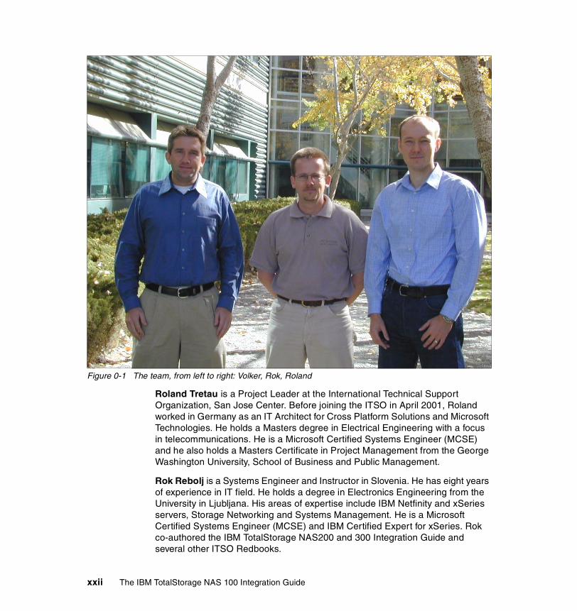
Figure 0-1 The team, from left to right: Volker, Rok, Roland
Roland Tretau is a Project Leader at the International Technical Support Organization, San Jose Center. Before joining the ITSO in April 2001, Roland worked in Germany as an IT Architect for Cross Platform Solutions and Microsoft Technologies. He holds a Masters degree in Electrical Engineering with a focus in telecommunications. He is a Microsoft Certified Systems Engineer (MCSE) and he also holds a Masters Certificate in Project Management from the George Washington University, School of Business and Public Management.
Rok Rebolj is a Systems Engineer and Instructor in Slovenia. He has eight years of experience in IT field. He holds a degree in Electronics Engineering from the University in Ljubljana. His areas of expertise include IBM Netfinity and xSeries servers, Storage Networking and Systems Management. He is a Microsoft Certified Systems Engineer (MCSE) and IBM Certified Expert for xSeries. Rok co-authored the IBM TotalStorage NAS200 and 300 Integration Guide and several other ITSO Redbooks.
xxii The IBM TotalStorage NAS 100 Integration Guide

Volker Seidel is a consultant for cross platform solutions in Germany. He has four years of experience in planning and implementing IT solutions for companies focusing on Linux/UNIX. He holds a bachelor-of-arts degree in business administration from the Hamburg Academy of Business Management. His areas of expertise include cross platform connectivity for SOLARIS, HP-UX, AIX, RedHat Linux with Windows based networks. He is also a certified HP 9000 Technical Professional.
Thanks to the following people for their contributions to this project:
Yvonne Lyon, Deanna Polm, Emma JacobsInternational Technical Support Organization, San Jose Center
Scott Hovey, Jeff Ottman, Thomas Daniels, Kevin Goldsmith, Richard Kisley, Douglas Dewey, Larry GoochIBM US
Hannes Brandt, Wolfgang Ebenhöch, Axel MüllerECS AG, Germany
Become a published authorJoin us for a two- to six-week residency program! Help write an IBM Redbook dealing with specific products or solutions, while getting hands-on experience with leading-edge technologies. You'll team with IBM technical professionals, Business Partners and/or customers.
Your efforts will help increase product acceptance and customer satisfaction. As a bonus, you'll develop a network of contacts in IBM development labs, and increase your productivity and marketability.
Find out more about the residency program, browse the residency index, and apply online at:
ibm.com/redbooks/residencies.html
Preface xxiii

Comments welcomeYour comments are important to us!
We want our Redbooks to be as helpful as possible. Send us your comments about this or other Redbooks in one of the following ways:
� Use the online Contact us review redbook form found at:
ibm.com/redbooks
� Send your comments in an Internet note to:
� Mail your comments to:
IBM Corporation, International Technical Support OrganizationDept. QXXE Building 80-E2650 Harry RoadSan Jose, California 95120-6099
xxiv The IBM TotalStorage NAS 100 Integration Guide

Chapter 1. The main concept behind Network Attached Storage
Given the expansive growth in both storage and network technology, it is not surprising that an easy-to-implement and scalable solution has been developed to meet the various storage needs.
Network Attached Storage (NAS) exploits the existing intermediate speed messaging network with a very easy-to-integrate storage solution.
In this book, we focus on NAS as a storage networking solution. Reading this book should adequately equip you to implement a NAS solution using one or more of the products we describe to meet your networked storage requirements.
This chapter includes the following sections:
� How this book is organized� Local Area Networks� Open Systems Interconnection (OSI) model� File systems and I/O� Network Attached Storage (NAS)� Industry standards
1
© Copyright IBM Corp. 2003. All rights reserved. 1

1.1 How this book is organizedBasically, here is how the material in this book is presented:
� First we provide the concepts and technical knowledge needed (Chapter 1, “The main concept behind Network Attached Storage” on page 1).
� Next we offer a brief overview of the IBM products we used (Chapter 2, “The IBM TotalStorage NAS 100 product” on page 23).
� Then we describe how to integrate the NAS 100 into your storage network (Chapter 3, “Implementing the IBM TotalStorage NAS 100” on page 35).
� After that we take a look at the advanced configuration of the NAS 100 system (Chapter 4, “Advanced NAS configuration” on page 69).
� After we have finished with the configuration part, we then show how to manage the NAS 100 system using IBM systems management tools (Chapter 5, “Systems management for the NAS 100” on page 107).
� Next we explain how to set up the NAS 100 as a cross platform storage solution (Chapter 6, “Cross platform storage” on page 171).
� Then we talk about backup, restore and troubleshooting, and we show how to integrate the Persistent Storage Manager (PSM). We show how it can be used with Tivoli Storage Manager and will give you tips for diagnostics on your NAS 100 appliance. We will also show recovery scenarios for a hard drive or partition failure (Chapter 7, “Backup, restore, troubleshooting” on page 231).
Most of this book is a hands-on guide to implementing the NAS 100 as part of a storage networking solution, but before we can leap into the how-to section, it is important that you understand a few of the basic concepts about networks and storage.
Note: If you are a seasoned storage networking professional and are already very familiar with this subject, feel free to skip ahead to Chapter 3, “Implementing the IBM TotalStorage NAS 100” on page 35. However, if you would like a quick primer, please read these first two chapters. They provide the background information you need to understand, not only how to proceed with the integration, but also what you stand to gain from doing so.
2 The IBM TotalStorage NAS 100 Integration Guide

1.2 Local Area NetworksA Local Area Network (LAN) is simply the connection of two or more computers (nodes) to facilitate data and resource sharing. They proliferated from the mid-1980s to address the problem of “islands of information” which occurred with standalone computers within departments and enterprises. LANs typically reside in a single or multiple buildings confined to a limited geographic area which is spanned by connecting two or more LANs together to form a Wide Area Network (WAN).
The design of LANs are based typically on open systems networking concepts. These concepts are described in the network model of the Open Systems Interconnection (OSI) standards of the International Standards Organization (ISO). The OSI model is described in detail in Figure 1-4, “Comparing the Internet protocol suite with the OSI reference model” on page 5.
LAN types are defined by their topology, which is simply how nodes on the network are physically connected together. A LAN may rely on a single topology throughout the entire network but typically has a combination of topologies connected using additional hardware. The primary topologies defined for Local Area Networks are:
Bus topologyIn a bus topology, all nodes are connected to a central cable, called the bus or backbone. Bus networks are relatively inexpensive and easy to install. Ethernet systems use a bus topology (Figure 1-1).
Figure 1-1 Bus topology
Ring topologyNodes in a ring topology are connected via a closed loop such that each node has two other nodes connected directly to either side of it. Ring topologies are more costly and can be difficult to install. The IBM Token Ring uses a ring topology (Figure 1-2).
Node1
Node2
Node3
Node4
Bus (Backbone)
Chapter 1. The main concept behind Network Attached Storage 3

Figure 1-2 Ring topology
Star topologyA star topology uses a centralized hub to connect the nodes in the network together. Star networks are easy to install and manage. However, bottlenecks occur since all of the network traffic travels through the hub. Ethernet systems also use a star topology (Figure 1-3).
Figure 1-3 Star topology
Node1
Node2
Node3
Node4
Ring
Node5
Node4
Node3
Node2
Star
Centralhub
Node1
4 The IBM TotalStorage NAS 100 Integration Guide

Today, Ethernet topologies are predominant. International Data Corporation (IDC) estimates more than 85% of all installed network connections worldwide are Ethernet. It is popular due to its simplicity, affordability, scalability, and manageability. Ethernet includes definitions of protocols for addressing, formatting and sequencing of data transmissions across the network and also describes the physical media (cables) used for the network.
1.3 Open Systems Interconnection (OSI) modelThe Open Systems Interconnection (OSI) model describes the layers in the network required for communication between computers. OSI is a seven layered model illustrated with the Internet protocol suite (or stack) in Figure 1-4. Each layer is responsible for a certain set of tasks associated with moving data across the network. Most Ethernet networks (including ours) communicate using the TCP/IP protocol. In this section, we discuss TCP/IP and how it relates to the OSI model since it is the default communication protocol for the NAS 100.
Figure 1-4 Comparing the Internet protocol suite with the OSI reference model
Application
TCP
IP
Device Driver and Hardware
(Subnet)
Internet protocol suite
Application
Presentation
Session
Transport
Network
Data Link
Physical
OSI model
7
6
5
4
3
2
1
Chapter 1. The main concept behind Network Attached Storage 5

1.3.1 Device driver and hardware layerAlso called the Subnet layer, the device driver and hardware layer comprises both the physical and data link layers of the OSI model. It is considered the hardware that is part of each node on the network. The hardware handles the electrical and mechanical aspects of data transfers, moving the bits across a physical link. The data link layer packages packets of data into frames, ensures that they arrive safely to the target destination, and encompasses error detection and correction.
1.3.2 Internet Protocol layerIn the OSI model, the Network layer finds the best route through the network to the target destination. It has little to do in a single discrete LAN; but in a larger network with subnets, or access to WAN’s, the Network layer works with the various routers, bridges, switches, gateways, and software, to find the best route for data packets.
The Internet Protocol (IP) layer in the Internet protocol suite performs the functions of the network layer. It is the common thread running through the Internet and most LAN technologies, including Ethernet. It is responsible for moving data from one host to another, using various “routing” algorithms. Layers above the network layer break a data stream into chunks of a predetermined size, known as packets or datagrams. The datagrams are then sequentially passed to the IP layer.
The job of the IP layer is to route these packets to the target destination. IP packets consist of an IP header, together with the higher level TCP protocol and the application datagram. IP knows nothing about the TCP and datagram contents. Prior to transmitting data, the network layer might further subdivide it into smaller packets for ease of transmission. When all the pieces finally reach the destination, they are reassembled by the network layer into the original datagram.
IP connectionless serviceThe IP is the standard that defines the manner in which the network layers of two hosts interact. These hosts may be on the same network, or reside on physically remote heterogeneous networks. IP was designed with inter-networking in mind. It provides a connectionless, best-effort packet delivery service. Its service is called connectionless because it is like the postal service rather than the telephone system. IP packets, like telegrams or mail, are treated independently. Each packet is stamped with the addresses of the receiver and the sender.
6 The IBM TotalStorage NAS 100 Integration Guide

Routing decisions are made on a packet-by-packet basis. On the other hand, connection-oriented, circuit switched telephone systems explicitly establish a connection between two users before any conversation takes place. They also maintain the connection for the entire duration of conversation.
A best-effort delivery service means that packets might be discarded during transmission, but not without a good reason. Erratic packet delivery is normally caused by the exhaustion of resources, or a failure at the data link or physical layer. In a highly reliable physical system such as an Ethernet LAN, the best-effort approach of IP is sufficient for transmission of large volumes of information. However, in geographically distributed networks, especially the Internet, IP delivery is insufficient. It needs to be augmented by the higher-level TCP protocol to provide satisfactory service.
The IP packetAll IP packets or datagrams consist of a header section and a data section (payload). The payload may be traditional computer data, or it may, commonly today, be digitized voice or video traffic. Using the postal service analogy again, the “header” of the IP packet can be compared with the envelope and the “payload” with the letter inside it. Just as the envelope holds the address and information necessary to direct the letter to the desired destination, the header helps in the routing of IP packets.
The payload has a maximum size limit of 65,536 bytes per packet. It contains error and/or control protocols, like the Internet Control Message Protocol (ICMP). To illustrate control protocols, suppose that the postal service fails to find the destination on your letter. It would be necessary to send you a message indicating that the recipient's address was incorrect. This message would reach you through the same postal system that tried to deliver your letter. ICMP works the same way: It packs control and error messages inside IP packets.
IP addressingAn IP packet contains a source and a destination address. The source address designates the originating node's interface to the network, and the destination address specifies the interface for an intended recipient or multiple recipients (for broadcasting).
Every host and router on the wider network has an address that uniquely identifies it. It also denotes the sub-network on which it resides. No two machines can have the same IP address. To avoid addressing conflicts, the network numbers are assigned by an independent body.
Chapter 1. The main concept behind Network Attached Storage 7

The network part of the address is common for all machines on a local network. It is similar to a postal code, or zip code, that is used by a post office to route letters to a general area. The rest of the address on the letter (i.e., the street and house number) are relevant only within that area. It is only used by the local post office to deliver the letter to its final destination.
The host part of the IP address performs a similar function. The host part of an IP address can further be split into a sub-network address and a host address.
Time to Live (TTL)The IP packet header also includes Time to Live (TTL) information that is used to limit the life of the packet on the network. It includes a counter that is decremented each time the packet arrives at a routing step. If the counter reaches zero, the packet is discarded.
1.3.3 TCP layerThe transport layer is responsible for ensuring delivery of the data to the target destination, in the correct format in which it was sent. In the event of problems on the network, the Transport layer finds alternative routes. It is also responsible for delivering the sequence of packets in the correct order. In the Internet protocol suite, the protocol operating in the transport layer is the Transmission Control Program (TCP).
The application data has no meaning to the Transport layer. On the source node, the transport layer receives data from the application layer and splits it into data packets or chunks. The chunks are then passed to the network layer. At the destination node, the transport layer receives these data packets and reassembles them before passing them to the appropriate process or application.
The Transport layer is the first end-to-end layer of the TCP/IP stack. This characteristic means that the transport layer of the source host can communicate directly with its peer on the destination host, without concern about 'how' data is moved between them. These matters are handled by the network layer. The layers below the transport layer understand and carry information required for moving data across links and subnetworks.
In contrast, at the transport layer or above, one node can specify details that are only relevant to its peer layer on another node. For example, it is the job of the transport layer to identify the exact application to which data is to be handed over at the remote end. This detail is irrelevant for any intermediate router. But it is essential information for the transport layers at both the ends.
8 The IBM TotalStorage NAS 100 Integration Guide

1.3.4 Application layerThe functions of the Session, Presentation, and Application layers of the OSI model are all combined in the Application layer of the Internet protocol suite. It encompasses initial logon, security, final termination of the session, interpretation services (compression, encryption, or formatting), and delivery of the network messages to the end user program.
The Application layer is the layer with which end users normally interact. It is responsible for formatting the data so that its peers can understand it. Whereas the lower three layers are usually implemented as a part of the OS, the application layer is a user process. Some application-level protocols that are included in most TCP/IP implementations, include:
� Telnet for remote login � File Transfer Protocol (FTP) for file transfer � Simple Mail Transfer Protocol (SMTP) for mail transfer
1.3.5 Protocol suitesA protocol suite (or protocol stack), as we saw in the Internet protocol suite, is organized so that the highest level of abstraction resides at the top layer. For example, the highest layer may deal with streaming audio or video frames, whereas the lowest layer deals with raw voltages or radio signals. Every layer in a suite builds upon the services provided by the layer immediately below it.
The terms protocol and service are often confused. A protocol defines the exchange that takes place between identical layers of two hosts. For example, in the IP suite, the transport layer of one host talks to the transport layer of another host using the TCP protocol. A service, on the other hand, is the set of functions that a layer delivers to the layer above it. For example, the TCP layer provides a reliable byte-stream service to the application layer above it.
Each layer adds a header containing layer-specific information to the data packet. A header for the network layer might include information such as source and destination addresses. The process of appending headers to the data is called encapsulation. Figure 1-5 shows how data is encapsulated by various
Note: You may see the different terms Internet protocol suite, TCP/IP suite, or TCP/IP stack. These are simply names for the same thing, the group of network layers to describe how two nodes on the Internet communicate.
Chapter 1. The main concept behind Network Attached Storage 9
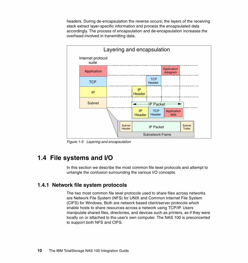
headers. During de-encapsulation the reverse occurs; the layers of the receiving stack extract layer-specific information and process the encapsulated data accordingly. The process of encapsulation and de-encapsulation increases the overhead involved in transmitting data.
Figure 1-5 Layering and encapsulation
1.4 File systems and I/OIn this section we describe the most common file level protocols and attempt to untangle the confusion surrounding the various I/O concepts.
1.4.1 Network file system protocolsThe two most common file level protocols used to share files across networks are Network File System (NFS) for UNIX and Common Internet File System (CIFS) for Windows. Both are network based client/server protocols which enable hosts to share resources across a network using TCP/IP. Users manipulate shared files, directories, and devices such as printers, as if they were locally on or attached to the user’s own computer. The NAS 100 is preconcerted to support both NFS and CIFS.
Application
TCP
IP
Subnet
Internet protocol suite
Application datagram
TCP Header
IP Header
Subnet Header
Subnet Trailer
IP Header
TCP Header
Application data
IP Packet
IP Packet
Subnetwork Frame
Layering and encapsulation
10 The IBM TotalStorage NAS 100 Integration Guide
Network File System (NFS)NFS servers make their file systems available to other systems in the network by exporting directories and files over the network. Once exported, an NFS client can then “mount” a remote file system from the exported directory location. NFS controls access by giving client-system level user authorization based on the assumption that a user who is authorized to the system must be trustworthy. Although this type of security is adequate for some environments, it is open to abuse by anyone who can access a UNIX system via the network.
For directory and file level security, NFS uses the UNIX concept of file permissions with User (the owner’s ID), Group (a set of users sharing a common ID), and Other (meaning all other user IDs). For every NFS request, the IDs are verified against the UNIX file permissions.
NFS is a stateless service. Therefore, any failure in the link will be transparent to both client and server. When the session is re-established the two can immediately continue to work together again.
NFS handles file locking by providing an advisory lock to subsequent applications to inform them that the file is in use by another application. The ensuing applications can decide if they want to abide by the lock request or not. This has the advantage of allowing any UNIX application to access any file at any time, even if it is in use. The system relies on “good neighbor” responsibility which, though often convenient, clearly is not foolproof. This is avoided by using the optional Network Lock Manager (NLM). It provides file locking support to prevent multiple instances of open files.
Common Internet File System (CIFS)Another method used to share resources across a network uses CIFS, which is a protocol based on the Microsoft Server Message Block (SMB) protocol. Using CIFS, servers create file shares which are accessible by authorized clients. Clients subsequently connect to the server’s shares to gain access to the resource.
Security is controlled at both the user and share level. Client authentication information is sent to the server before the server will grant access. CIFS uses access control lists that are associated with the shares, directories, and files, and authentication is required for access.
A session in CIFS is oriented and stateful. This means that both client and server share a history of what is happening during a session, and they are aware of the activities occurring. If there is a problem, and the session has to be re-initiated, a new authentication process must be completed.
Chapter 1. The main concept behind Network Attached Storage 11

CIFS employs opportunistic locks (oplocks) to control file access. Depending on the type of locking mechanism required by the client, CIFS offers nodes the ability to cache read or write data from the file being accessed to improve network performance. Exclusive rights to the file prevents other nodes on the network from gaining access to that file until it is closed. During a CIFS session the lock manager has historical information concerning which client has opened the file, for what purpose, and in which sequence.
1.4.2 Understanding I/OA major source of confusion regarding NAS is the concept of File I/O versus Block I/O. We try to shed a little light on this subject here. Understanding the difference between these two forms of data access is crucial to realizing the potential benefits of any SAN-based or NAS-based solution.
When a partition on a hard drive is under the control of an operating system (OS), the OS will format it. Formatting of the partition occurs when the OS lays a file system structure on the partition. This file system is what enables the OS to keep track of where it stores data. The file system is an addressing scheme the OS uses to map data on the partition. Now, when you want to get to a piece of data on that partition, you must request the data from the OS that controls it. For example, suppose that Windows 2000 formats a partition (or drive) and maps that partition to your system. Every time you request to open data on that partition, your request is processed by Windows 2000. Since there is a file system on the partition, it is accessed via File I/O. Additionally, you cannot request access to just the last 10 KB of a file. You must open the entire file, which is another reason that this method is referred to as File I/O.
Block I/O (raw disk) is handled differently: There is no OS format done to lay out a file system on the partition. The addressing scheme that keeps up with where data is stored is provided by the application using the partition. An example of this would be DB2 using its tables to keep track of where data is located rather than letting the OS do that job. That is not to say that DB2 cannot use the OS to keep track of where files are stored. It is just more efficient, for the database to bypass the cost of requesting the OS to do that work.
Using File I/O is like using an accountant. Accountants are good at keeping up with your money for you, but they charge you for that service. For your personal checkbook, you probably want to avoid that cost. On the other hand, for a corporation where many different kinds of requests are made, an accountant is a good idea. That way, checks are not written when they should not be. When sharing files across a network, something needs to control when writes can be done. The operating system fills this role. It does not allow multiple writes at the
12 The IBM TotalStorage NAS 100 Integration Guide

same time, even though many write requests are made. Databases are able to control this writing function on their own so in general they run faster by skipping the OS although this depends on the efficiency of the implementation of file system and database.
For a more in-depth study of these topics, refer to the redbook, IP Storage Networking: IBM NAS and iSCSI Solutions, SG24-6240.
1.5 Network Attached Storage (NAS)Storage devices which optimize the concept of file sharing across the network have come to be known as Network Attached Storage (NAS). NAS solutions utilize the mature Ethernet IP network technology of the LAN. Data is sent to and from NAS devices over the LAN using TCP/IP.
By making storage devices LAN addressable, the storage is freed from its direct attachment to a specific server and any-to-any connectivity is facilitated using the LAN fabric. In principle, any user running any operating system can access files on the remote storage device. This is done by means of a common network access protocol, for example, NFS for UNIX servers, and CIFS for Windows servers.
A storage device cannot just attach to a LAN. It needs intelligence to manage the transfer and the organization of data on the device. The intelligence is provided by a dedicated server to which the common storage is attached. It is important to understand this concept. NAS comprises a server, an operating system, plus storage which is shared across the network by many other servers and clients. So NAS is a device, rather than a network infrastructure, and shared storage is either internal to the NAS device or attached to it.
1.5.1 File serversEarly NAS implementations in the late 1980s used a standard UNIX or NT server with NFS or CIFS software to operate as a remote file server. In such implementations, clients and other application servers access the files stored on the remote file server, as though the files are located on their local disks. The location of the file is transparent to the user.
Chapter 1. The main concept behind Network Attached Storage 13

Several hundred users could work on information stored on the file server, each one unaware that the data is located on another system. The file server has to manage I/O requests accurately, queuing as necessary, fulfilling the request and returning the information to the correct initiator. The NAS server handles all aspects of security and lock management. If one user has the file open for updating, no-one else can update the file until it is released. The file server keeps track of connected clients by means of their network IDs, addresses, and so on.
1.5.2 Network appliancesMore recent developments use application specific, specialized, “thin server” configurations with customized operating systems, usually comprising a stripped down UNIX kernel, reduced Linux OS, or a specialized Windows 2000 kernel, as with the IBM TotalStorage NAS appliances. In these reduced operating systems, many of the server operating system functions are not supported. The objective is to improve performance and reduce costs by eliminating unnecessary functions normally found in the standard hardware and software. Some NAS implementations also employ specialized data mover engines and separate interface processors in efforts to further boost performance.
These specialized file servers with a reduced OS are typically known as appliances, describing the concept of an application specific system. The term “appliance” borrows from household electrical devices the idea of a specialized application specific tool, such as a coffee maker or a toaster. NAS appliances, like the IBM TotalStorage NAS 100, 200 and 300, typically come with pre-configured software and hardware, and with no monitor or keyboard for user access. This is commonly termed a “headless” system. A storage administrator accesses the appliance and manages the disk resources from a remote console.
One of the typical characteristics of a NAS appliance is its ability to be installed rapidly using minimal time and effort to configure the system. It is integrated seamlessly into the network as shown in Figure 1-6. This approach makes NAS appliances especially attractive when lack of time and skills are elements in the decision process.
14 The IBM TotalStorage NAS 100 Integration Guide

Figure 1-6 The role of the NAS 100 in your storage network
So, a NAS appliance is an easy to use device, which is designed for a specific function, such as serving files to be shared among multiple clients. It performs this task very well. It is important to recognize this when selecting a NAS solution. It is not a general purpose server, and should not be used (indeed, due to its reduced OS, probably cannot be used) for general purpose server tasks. However, it does provide a good solution for appropriately selected shared storage applications.
1.5.3 NAS uses File I/OOne of the key differences of a NAS disk device, compared to direct access storage (DAS) is that all I/O operations use file level I/O protocols. File I/O is a high level type of request that, in essence, specifies only the file to be accessed, but does not directly address the storage device. This is done later by other operating system functions in the remote NAS appliance.
A File I/O request specifies the file and the offset into the file. For instance, the I/O may specify “Go to byte ‘1000’ in the file (as if the file was a set of contiguous bytes), and read the next 256 bytes beginning at that position”. Unlike Block I/O, there is no awareness of a disk volume or disk sectors in a File I/O request. Inside the NAS appliance, the operating system keeps track of where files are located on disk. The OS issues a Block I/O request to the disks to fulfill the File I/O read and write requests it receives.
IPNetwork
Specialized NAS Appliance
Ethernet
Chapter 1. The main concept behind Network Attached Storage 15
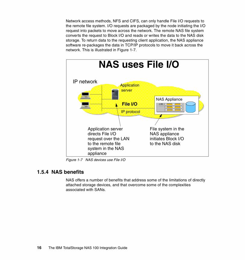
Network access methods, NFS and CIFS, can only handle File I/O requests to the remote file system. I/O requests are packaged by the node initiating the I/O request into packets to move across the network. The remote NAS file system converts the request to Block I/O and reads or writes the data to the NAS disk storage. To return data to the requesting client application, the NAS appliance software re-packages the data in TCP/IP protocols to move it back across the network. This is illustrated in Figure 1-7.
Figure 1-7 NAS devices use File I/O
1.5.4 NAS benefitsNAS offers a number of benefits that address some of the limitations of directly attached storage devices, and that overcome some of the complexities associated with SANs.
NAS uses File I/O
Application server
IP protocol
File I/O
File system in the NAS appliance initiates Block I/O to the NAS disk
Application server directs File I/O request over the LAN to the remote file system in the NAS appliance
IP network
NAS Appliance
16 The IBM TotalStorage NAS 100 Integration Guide

Resource poolingA NAS appliance enables disk storage capacity to be consolidated and pooled on a shared network resource, at great distances from the clients and servers which will share it. Thus a NAS device can be configured as one or more file systems, each residing on specified disk volumes. All users accessing the same file system are assigned space within it on demand. This contrasts with individual DAS storage, when some users may have too little storage, and others may have too much.
Consolidation of files onto a centralized NAS device can minimize the need to have multiple copies of files spread on distributed clients. Thus overall hardware costs can be reduced.
NAS pooling can reduce the need to physically reassign capacity among users. The results can be lower overall costs through better utilization of the storage, lower management costs, increased flexibility, and increased control.
Exploits existing infrastructureBecause NAS utilizes the existing LAN infrastructure, there are minimal costs of implementation. Introducing a new network infrastructure, such as a Fibre Channel SAN, can incur significant hardware costs. In addition, new skills must be acquired, and a project of any size will need careful planning and monitoring to bring it to completion.
Simple to implementBecause NAS devices attach to mature, standard LAN implementations, and have standard LAN addresses, they are typically extremely easy to install, operate, and administer. This plug-and-play operation results in lower risk, ease of use, and fewer operator errors, all of which contributes to lower costs of ownership.
Enhanced choiceThe storage decision is separated from the server decision, thus enabling the buyer to exercise more choice in selecting equipment to meet the business needs.
ConnectivityLAN implementation allows any-to-any connectivity across the network. NAS appliances may allow for concurrent attachment to multiple networks, thus supporting many users.
Chapter 1. The main concept behind Network Attached Storage 17

ScalabilityNAS appliances can scale in capacity and performance within the allowed configuration limits of the individual appliance. However, this may be restricted by considerations such as LAN bandwidth constraints, and the need to avoid restricting other LAN traffic.
Heterogeneous file sharingRemote file sharing is one of the basic functions of any NAS appliance. Multiple client systems can have access to the same file. Access control is serialized by NFS or CIFS. Heterogeneous file sharing may be enabled by the provision of translation facilities between NFS and CIFS, as with the NAS 100.
Improved manageabilityBy providing consolidated storage, which supports multiple application systems, storage management is centralized. This enables a storage administrator to manage more capacity on a NAS appliance than typically would be possible for distributed, directly attached storage.
Enhanced backupNAS appliance backup is a common feature of most popular backup software packages. For instance, the IBM TotalStorage NAS appliances all provide TSM client software support. Some NAS appliances have some integrated, automated backup facility to tape, enhanced by the availability of advanced functions such as the IBM NAS appliance facility called Persistent Storage Manager (PSM). This enables multiple point-in-time copies of files to be created on disk, which can be used to make backup copies to tape in the background. This is similar in concept to features such as IBM’s Snapshot function on the IBM RAMAC Virtual Array (RVA).
1.5.5 Other NAS considerationsOn the converse side of the storage network decision, you need to take into consideration the following factors regarding NAS solutions.
Proliferation of NAS devicesPooling of NAS resources can only occur within the capacity of the individual NAS appliance. As a result, in order to scale for capacity and performance, there is a tendency to grow the number of individual NAS appliances over time, which can increase hardware and management costs.
18 The IBM TotalStorage NAS 100 Integration Guide
Software overhead impacts performanceAs we explained earlier, TCP/IP is designed to bring data integrity to Ethernet-based networks by guaranteeing data movement from one place to another. The trade-off for reliability is a software intensive network design which requires significant processing overheads, which can consume more than 50% of available processor cycles when handling Ethernet connections. This is not normally an issue for applications such as Web-browsing, but it is a drawback for performance intensive storage applications.
Consumption of LAN bandwidthEthernet LANs are tuned to favor short burst transmissions for rapid response to messaging requests, rather than large continuous data transmissions. Significant overhead can be imposed to move large blocks of data over the LAN. The maximum packet size for Ethernet is 1518 bytes. A 10 MB file has to be segmented into more than 7000 individual packets. Each packet is sent separately to the NAS device by the Ethernet collision detect access method. As a result, network congestion may lead to reduced or variable performance.
Data integrityThe Ethernet protocols are designed for messaging applications, so data integrity is not of the highest priority. Data packets may be dropped without warning in a busy network, and have to be resent. Since it is up to the receiver to detect that a data packet has not arrived, and to request that it be resent, this can cause additional network traffic.
With NFS file sharing there are some potential risks. Security controls can fairly easily be by-passed. This may be a concern for certain applications. Also the NFS file locking mechanism is not foolproof, so that multiple concurrent updates could occur in some situations.
Impact of backup/restore applicationsOne of the potential downsides of NAS is the consumption of substantial amounts of LAN bandwidth during backup and restore operations, which may impact other user applications. NAS devices may not suit applications which require very high bandwidth. To overcome this limitation, some users implement a dedicated IP network for high data volume applications, in addition to the messaging IP network. This can add significantly to the cost of the NAS solution.
Chapter 1. The main concept behind Network Attached Storage 19

1.5.6 Total cost of ownershipBecause it makes use of both existing LAN network infrastructures and network administration skills already employed in many organizations, NAS costs may be substantially lower than for directly attached or SAN-attached storage. Specifically, NAS-based solutions offer the following cost-reducing benefits:
� They reduce administrative staff requirements.� They improve reliability and availability.� They bridge the gap between UNIX and Windows environments.
Reduced administrative staff requirementsImplementing single or clustered NAS appliances to manage your networked storage concentrates the administrative tasks and thereby reduces the number of people required to maintain the network. Since the NAS appliance is a headless system, administration is usually performed via a Web-based GUI interface accessible from anywhere on the network. In addition, more capacity can be managed per administrator, thus resulting in a lower cost of ownership.
Improved reliability and availabilityIn today’s business world, it has become the de facto standard to provide customers access to information 24 hours per day, 7 days per week, allowing very little time available for unplanned outages. Some IBM NAS appliances offer the ability to provide great availability with options for clustered models.
Bridges the gap between UNIX and Windows environmentsMost companies today contain heterogeneous operating environments. A NAS solution offers customers the ability for true cross-platform file sharing between Windows and UNIX clients by offering support for CIFS and NFS. This becomes increasingly important when application data becomes more common across platforms.
1.6 Industry standardsThere is a clear customer need for standardization within the storage networking industry to allow users to freely select equipment and solutions, knowing that they are not tying themselves to a proprietary or short term investment. To this end, there are extensive efforts among the major vendors in the storage networking industry to cooperate in the early agreement, development, and adoption of standards. A number of industry associations, standards bodies, and company groupings are involved in developing and publishing storage networking standards. The most important of these are the Storage Networking Industry Association (SNIA) and the Internet Engineering Task Force (IETF).
20 The IBM TotalStorage NAS 100 Integration Guide
In addition, IBM, IBM Business Partners, and other major vendors in the industry, have invested heavily in inter-operability laboratories. The IBM laboratories in Gaithersburg (Maryland, USA), Mainz (Germany), and Tokyo (Japan) are actively testing equipment from IBM and many other vendors, to facilitate the early confirmation of compatibility between multiple vendors servers, storage, and network hardware and software components.
1.6.1 Storage Networking Industry AssociationThe Storage Networking Industry Association (SNIA) is an international computer industry forum of developers, integrators, and IT professionals who evolve and promote storage networking technology and solutions. SNIA was formed to ensure that storage networks become efficient, complete, and trusted solutions across the IT community.
SNIA is accepted as the primary organization for the development of SAN and NAS standards, with over 150 companies and individuals as its members, including all the major server, storage, and fabric component vendors. SNIA is committed to delivering architectures, education, and services that will propel storage networking solutions into a broader market.
IBM is one of the founding members of SNIA, and has senior representatives participating on the board and in technical groups. For additional information on the various activities of SNIA, see its Web site at:
http://www.snia.org
1.6.2 Internet Engineering Task ForceThe Internet Engineering Task Force (IETF) is a large open international community of network designers, operators, vendors, and researchers concerned with the evolution of the Internet architecture and the smooth operation of the Internet. It is open to any interested individual. The actual technical work of the IETF is done in its working groups, which are organized by topic into several areas (for example, routing, transport, and security).
For more information on the IETF and its work groups, refer to:
http://www.ietf.org
Chapter 1. The main concept behind Network Attached Storage 21

22 The IBM TotalStorage NAS 100 Integration Guide

Chapter 2. The IBM TotalStorage NAS 100 product
In this chapter we provide a brief overview of the IBM TotalStorage NAS products used during the development of this IBM Redbook. NAS appliances like the IBM TotalStorage Network Attached Storage 100 are fully integrated and dedicated storage solutions that can be quickly and easily attached to an IP network. Their storage will then become immediately and transparently available as a network file-serving resource to all clients. These specialized appliances are also independent of their client platforms and operating systems. Thus, NAS appliances appear to the client application as just another server.
In the following sections, we describe the new features:
� IBM TotalStorage NAS features and benefits� IBM TotalStorage Network Attached Storage 100� NAS 100 disk organization� The IBM TotalStorage NAS Version 2.5 at a glance
However, do be aware that, due to the rapidly-changing nature of this business, there may already be another update available. Therefore, we recommend that you check the following Web link for the most current specifications on the IBM TotalStorage NAS product family:
http://www.storage.ibm.com/snetwork/index.html
2
© Copyright IBM Corp. 2003. All rights reserved. 23

2.1 IBM TotalStorage NAS features and benefitsThe NAS 100 is an appliance that is designed to work in heterogeneous environments right out of the box. Figure 2-1 visually demonstrates how the built-in features of the NAS 100 allow it to plug into almost any environment.
Figure 2-1 Visualization of interoperability features on NAS 100
2.1.1 Included softwareThe software listed in Table 2-1 is included in the NAS 100.
Table 2-1 NAS 100 software
Software IBM TotalStorage NAS 100 Model R12
Operating system Windows Powered OS
Data Protection Columbia Data Products Persistent Storage Manager enables 250 point-in-time True Image data views.
Backup/restore management Windows NT/2000 Backup
24 The IBM TotalStorage NAS 100 Integration Guide

2.1.2 Preloaded and optional softwareEach NAS 100 is preloaded at the factory with its base operating system, installation and administration software. The code is loaded to the system's hard disk with a backup operating system on the second, mirrored partition. The operating system and NAS application code have been specifically tuned to enable the NAS 100 as high performance NAS server appliances.
In addition to the operating system and application software, each unit contains tools which simplify remote configuration and administration tasks. Additionally, included network management agents provide options for managing the units.
Specifically, the units come preconfigured with the following functions:
� Windows Powered OS:
– Windows 2000 Advanced Server code optimized for the IBM TotalStorage NAS 100 Models
� Multiple file systems support:
– CIFS– NFS– Netware– Apple File Protocol
� Multiple file transfer services:
– FTP– HTTP
� Remote NAS system administration
– Administrative tasks can be performed in the Web-based GUI– IBM Advanced Appliance Configuration Utility– Alternate administrative task performed using Windows Terminal Service– Advanced management functions available via Windows Terminal Service– Simple point-and-click for restores using Windows NT Backup– NAS Backup Assistant MMC Snap-in Web page
Backup/restore management Tivoli Storage Manager Client(V4.2.1.20)
Systems management IBM Director 3.1 agent
Remote Administration Web-based GUIMicrosoft Terminal Services
Software IBM TotalStorage NAS 100 Model R12
Chapter 2. The IBM TotalStorage NAS 100 product 25
� UNIX services:
– Pre-configured NFS support– Web-based GUI for performing administrative tasks– Microsoft Services for UNIX V2.2+QFE– NFS V3.0 (IETF RFC 1830)
� Setup tutorial:
– NAS Setup Navigator will help you in the setup process.
� Automatic recovery of operating system:
– Customer scheduled backups of operating system partition.
– Original factory reload of operating system.
– The NAS Backup Assistant is a GUI front end to IBMSNAP that generates a batch file that invokes NT Backup from settings configured by the user in the GUI.
� Advanced Aggregate Management:
– IBM Director Agent V3.1
� Persistent Storage Manager (PSM) for IBM NAS
Persistent Storage Manager (PSM) creates True Images (these are multiple point-in-time persistent images of any or all system and data volumes). All persistent images survive system power loss or a planned or unplanned reboot. Each instance of PSM seamlessly handles 250 concurrent images of up to 255 independent volumes for a total of 63,750 independent data images. Any image can be easily managed through the Microsoft Web user interface, and accessed the same as any other active volume.
In case of data corruption or loss, any persistent image can be used for manual retrieval of individual files (by the administrator or end users), or more importantly, for instant restoration (by a PSM function initiated by the administrator, in the Web user interface) of the entire volume from image, which can substantially reduce the amount of system down time.
– Persistent Storage Manager creates and keeps multiple point-in-time persistent images (maximum of 250 concurrent images of up to 255 independent volumes).
– All images for a volume are mounted under a single directory (in the root directory of the volume), with each image under its own mount point.
– User-level access can be granted to one or more of the images, to allow users to restore their own files from the images (users automatically have the same access privileges to individual files and directories in the images that they would have on the actual volume).
26 The IBM TotalStorage NAS 100 Integration Guide

– Images can be read-only, or read-write (with ability to reset (undo changes to) read-write images).
– Images can be assigned retention levels (if an image needs to be automatically deleted by PSM, the highest priority images can be kept).
– Any image can be used to restore an entire volume instantly (for data volumes, typically within seconds; for system volume, system reboot is required).
– Flexible, configurable image access and administration via Web-based user interface.
– Schedule images (for each schedule entry (image group), specify interval, number to keep, image name, properties (read-only or read-write, retention level).
– Create a new image immediately (specify name and properties).
– Delete images.
– View and change properties of images (also reset read-write images).
– Restore a volume (from any image of that volume).
– Configure advanced parameters:
• Maximum number of images to keep concurrently• Name of image root directory • Quiescent period and quiescent period wait time-out• Size of the image cache file (per volume)
– Image cache file usage warning and automatic image deletion thresholds (per volume).
� IBM Director with Universal Manageability (UM) Services V3.1:
The IBM TotalStorage NAS 100 units contain a IBM Director Agent and can be managed by this powerful, highly-integrated, systems management software solution that is built upon industry standards and designed for ease-of-use. Using its intuitive Java-based GUI, an administrator can centrally manage individual or large groups of IBM and non-IBM PC-based servers. IT administrators can view the hardware configuration of remote systems in detail and monitor the usage and performance of crucial components, such as processors, disks, and memory.
The following functions for NAS have been added in V3.1. You can:
– Learn detailed inventory information about the deployed NAS, including operating system, memory, network card and hardware.
– Track all managed NAS boxes operatively with features such as power management, event log and system monitor capabilities.
Chapter 2. The IBM TotalStorage NAS 100 product 27

– Upwardly integrate with Tivoli Enterprise, Tivoli NetView, Computer Associated Unicenter, HP Openview, Microsoft SMS, and Intel LANDesk Management Suite.
IBM Director with UM Services V3.1 is the latest update to IBM world-class systems manageability solutions. V3.1 replaces all earlier versions of NF Director and UM Services.
Several solutions have been designated Proven for the IBM TotalStorage Proven Program. We recommend that you visit the following Web link to get more information about proven network solutions:
http://www.storage.ibm.com/proven/nas.htm
2.1.3 Limitations of the Windows Powered OSThere are some limitations in the Windows Powered OS running on the NAS units. The operating system is tuned for optimal performance, but the following functions cannot be used with an IBM NAS appliance:
� Windows Domain Controller� DHCP Server� DNS Server� WINS Server
2.1.4 IBM Advanced Appliance Configuration Utility ToolThe IBM Advanced Appliance Configuration Utility tool helps you set or reconfigure the network configuration for one or many appliance servers. This software consists of an agent on each appliance server and a Java application residing on a Windows-based client workstation acting as a configuration station.
You can use this configuration station to do the following:
� Discover appliance servers.
� Set up and manage server network configurations.
� Launch the comprehensive Web-based server management console in a separate browser window.
Network administrators not currently running DHCP servers will find the advanced appliance configuration utility particularly useful for automatically configuring network settings for newly added IBM TotalStorage NAS appliances. Even administrators with networks using DHCP servers can benefit from the advanced appliance configuration utility, by permanently assigning IP addresses and host names automatically and launching Web-based management.
28 The IBM TotalStorage NAS 100 Integration Guide

2.2 IBM TotalStorage Network Attached Storage 100The IBM TotalStorage NAS 100, 5190 Model R12, is the newest member of IBM's growing family of Network Attached Storage (NAS) products, joining the TotalStorage NAS 200, NAS 300, and NAS 300G as the entry-level family member. It is a low profile (1U) table top NAS solution designed for central management of your remote and branch locations' data storage needs.
As a member of the IBM NAS family of products, the NAS 100 is characterized by many of the same outstanding features and attributes as those of other NAS family members. Those features include preloaded operating systems and application code, integrated software functions that help ease configuration and use, ease of deployment in the network, as well as built-in tools to facilitate remote management and systems management. The NAS 100 supports the major industry-standard file protocols: CIFS, NFS, NetWare, Apple File Protocol, HTTP, and FTP.
The IBM TotalStorage NAS 100 is a high-performance network storage device designed for a variety of Ethernet LAN storage applications. The NAS 100 is intended primarily for mid-size and large enterprise customers with many remote branch locations or distributed offices who desire centralized management of their IT infrastructure.
The NAS 100 supports applications such as home page directories and e-mail archival. Other applications include desktop publishing, illustration, photo imaging, and archival of document images such as legal documents, job tickets, or shipping manifests.
In comparison, the NAS 200 is designed to support storage applications for departments, workgroups, general/medium sized business customers, and service providers who require the advantages that network attached storage can provide and who need the added scalability and capacity provided by the NAS 200.
The NAS 100 is also well suited for many of the same applications as the NAS 200. The main differences between the NAS 100 and the NAS 200 are in the areas of HDD type (ATA versus SCSI), memory size, scalability and maximum storage capacity, support of the Remote Supervisor Adapter (RSA) to augment the function of the IBM Director management functions, and the rack space requirement (1U versus 3U). Both use the same Microsoft operating system.
The 100 series products provide these important advantages:
� High reliability via redundant, hot swap hard disk drives so business operations can continue in the event of a sub-system failure.
Chapter 2. The IBM TotalStorage NAS 100 product 29

� 250 persistent True Image data views provide quick data protection, enable backups without slowing the system and allow files and volumes to be restored quickly and accurately.
� Low-cost entry into network attached storage for customers who are reducing their use of general purpose servers.
� Multi-protocol support for CIFS (Windows), NFS (Unix), FTP, HTTP, Apple Talk and Novell file systems enables the sharing of files between and within any of these environments, eliminating the need for separate, dedicated file servers for each protocol.
� Excellent performance to enhance productivity for users in both Windows and mixed Windows/UNIX environments.
� Fully integrated, pre-loaded software suite that minimizes setup time — a minimum amount of dedicated IT resource is required for setup due to simplified installation and integration into the IP network via an easy-to-use Web browser.
� On-board Advanced System Management processor with Light Path Diagnostics, Predictive Failure Analysis and Remote Connect capabilities to help ensure system up time.
All of the details can be found at:
http://www.storage.ibm.com/snetwork/nas/100/index.html
Figure 2-2 shows a picture of the IBM TotalStorage NAS 100 rack model.
Figure 2-2 The IBM Network Attached Storage 100 model R12
30 The IBM TotalStorage NAS 100 Integration Guide

Figure 2-3 presents an inside view of the NAS 100 system.
T
Figure 2-3 NAS 100 inside view
These are the highlights for the IBM TotalStorage NAS 100:
� The NAS 100 is a 1U-high, table top or 19-inch rack-mountable system (using the optional feature, Rack Mounting Kit) with a 1.26 GHz Pentium III processor, 512 MB ECC memory.
� The NAS 100 includes four 120 GB slim-high, 3.5-inch ATA HDDs. The rotational speed of the drives is 7200 rpm. They are all hot swappable; they can be removed or inserted with the power on. Operation of the NAS 100 is capable of continuing even with one of the drives removed.
� Two 10/100/1000 Mbps RJ-45 ports for Ethernet connections are located on the back of the NAS 100. These Ethernet connections are full-duplex and auto-sensing.
� The NAS 100 supports Software RAID 0, 1, and 5.
� The hot swap HDD support and support for RAID auto-rebuilding are not available on other solutions on the market.
Chapter 2. The IBM TotalStorage NAS 100 product 31

2.3 NAS 100 disk organizationNAS 100 Appliances disks are preconfigured. Primary and secondary OS are mirrored in RAID 1 with a total capacity of 7.81 GB. The remaining disk space is configured as RAID 5 for customer data with a total capacity of 321 GB (Figure 2-4).
Figure 2-4 NAS 100 disk organization
7.81 GB Primary OS
Disk 2
7.81 GBBackup OS
Disk 3
7.81 GBBackup OS
Disk 4
7.81 GB Primary OS
Disk 1
7.81 GB Primary OS
NAS 100 Disk Organization
RAID 1 - Mirrored (D:)
RAID 5 - Raw 416GB: Usable 311 GB (E:)
RAID 1 - Mirrored (C:)
32 The IBM TotalStorage NAS 100 Integration Guide

2.4 The IBM TotalStorage NAS Version 2.5 at a glanceTable 2-2 provides an overview of the new highlights of the IBM TotalStorage NAS 100, 200, and 300 comparisons.
Table 2-2 Comparison of features — Release 2.5 for NAS 100, 200, and 300
Enhancement NAS 100Model R12
NAS 200Model 201
NAS 300Model 226
Processor 1.26 GHz 1.33 GHz 1.33 GHz
Dual Processor Option no yes yes
Operating System Windows Powered OS
Windows Powered OS
Windows Powered OS
Memory 512 MB 512 MB to 2.5 GB 1 GB to 3 GB
Capacity 480 GB 109 GB to 1.68 TB 109 GB to 3.51 TB
Disk Technology ATA SCSI SCSI
Slots 1 PCI 5 PCI PCI
IBM Director yes yes yes
Remote Supervisor Adapter Option
no yes yes
Chapter 2. The IBM TotalStorage NAS 100 product 33

34 The IBM TotalStorage NAS 100 Integration Guide

Chapter 3. Implementing the IBM TotalStorage NAS 100
In this chapter we explain how to configure the IBM TotalStorage NAS 100 from the very beginning. We cover these topics:
� Initial configuration� Configuration and administration tools� NAS Setup Navigator overview� Using the Navigator to set up the NAS 100
3
© Copyright IBM Corp. 2003. All rights reserved. 35
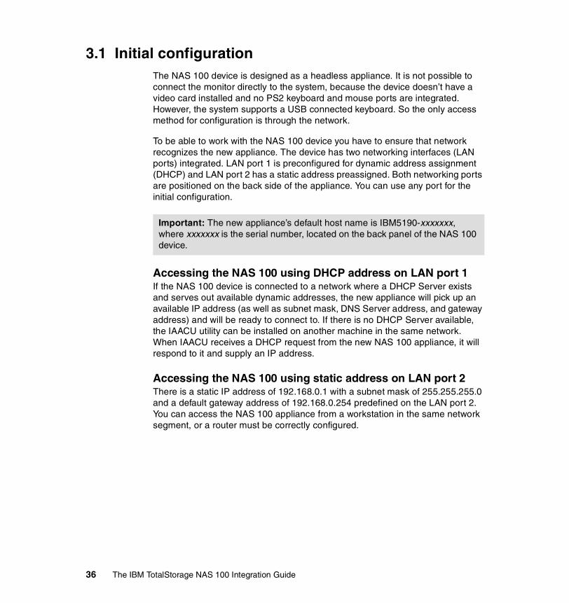
3.1 Initial configurationThe NAS 100 device is designed as a headless appliance. It is not possible to connect the monitor directly to the system, because the device doesn’t have a video card installed and no PS2 keyboard and mouse ports are integrated. However, the system supports a USB connected keyboard. So the only access method for configuration is through the network.
To be able to work with the NAS 100 device you have to ensure that network recognizes the new appliance. The device has two networking interfaces (LAN ports) integrated. LAN port 1 is preconfigured for dynamic address assignment (DHCP) and LAN port 2 has a static address preassigned. Both networking ports are positioned on the back side of the appliance. You can use any port for the initial configuration.
Accessing the NAS 100 using DHCP address on LAN port 1If the NAS 100 device is connected to a network where a DHCP Server exists and serves out available dynamic addresses, the new appliance will pick up an available IP address (as well as subnet mask, DNS Server address, and gateway address) and will be ready to connect to. If there is no DHCP Server available, the IAACU utility can be installed on another machine in the same network. When IAACU receives a DHCP request from the new NAS 100 appliance, it will respond to it and supply an IP address.
Accessing the NAS 100 using static address on LAN port 2There is a static IP address of 192.168.0.1 with a subnet mask of 255.255.255.0 and a default gateway address of 192.168.0.254 predefined on the LAN port 2. You can access the NAS 100 appliance from a workstation in the same network segment, or a router must be correctly configured.
Important: The new appliance’s default host name is IBM5190-xxxxxxx, where xxxxxxx is the serial number, located on the back panel of the NAS 100 device.
36 The IBM TotalStorage NAS 100 Integration Guide

3.1.1 Methods for setting up the NAS 100 deviceThere are two methods to configure the basic settings:
� Easy Setup using a browser: This is recommended for initial configuration.
� IBM Advanced Appliance Configuration Utility (IAACU): This is an alternative method to set up the networking parameters.
Using Easy Setup for initial configurationEasy Setup is part of a complete configuration and management tool called Windows Powered Server Appliance Tasks, which comes preloaded with the NAS 100 appliance. Easy Setup is intended to be used for setting or changing the administrator password, configuring the network settings, and defining the host name and share. To access it, use a Microsoft Internet Explorer browser.
1. Open the browser and enter the system name, then continue by clicking Next, as shown in Figure 3-1:
� For a secured port, type: https://IBM5190-xxxxxxx:8098,
where xxxxxxx is the serial number on the back of the NAS 100 appliance.
� For an unsecured port, type: http://IBM5190-xxxxxxx:8099.
Note: To be able to use different configuration and management tools to manage the NAS 100 appliance, it is recommended that you set Microsoft Internet Explorer 5.x (or later) as your default browser.
Chapter 3. Implementing the IBM TotalStorage NAS 100 37
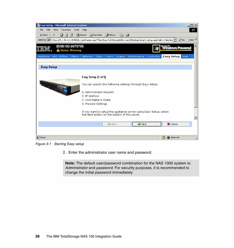
Figure 3-1 Starting Easy setup
2. Enter the administrator user name and password.
Note: The default user/password combination for the NAS 1000 system is: Administrator and password. For security purposes, it is recommended to change the initial password immediately
38 The IBM TotalStorage NAS 100 Integration Guide

3. After you change it, continue by clicking Next, as shown in Figure 3-2.
Figure 3-2 Administrator Account
4. The Easy Setup IP Address panel appears. Here you can set the configuration mode (DHCP or static) for both LAN ports and configure the IP address, subnet mask, default gateway, and the DNS server address. Notice that the Easy Setup senses whether the network cable is connected to the LAN port and displays this under the heading Status (Figure 3-3).
Note: If the IP address for a particular port is static, the DNS server address must also be specified statically.
Chapter 3. Implementing the IBM TotalStorage NAS 100 39

Figure 3-3 Setting IP addresses
5. After clicking Next, the Host Name & Share panel is presented. Here you can change the default host name. This is not recommended, though, as you will not be able to use IAACU. In the bottom part of this panel you can configure a share. Enter the Share name, path, and type, as shown in Figure 3-4. If you need to create and manage more than one share, use the Shares tab at the top of this panel. When you are done, click Next.
Note: If you select UNIX (NFS) checkbox under the Share type, you need to map the Unix user to the Windows user using Services for UNIX. If you don’t do this, your user will only have limited privileges. For more information, see Chapter , “Configuring the User Name Mapping” on page 207.
40 The IBM TotalStorage NAS 100 Integration Guide

Figure 3-4 Changing a host name and creating a Share
6. In the Summary panel you can preview the settings. The ones which were changed are shown in shaded boxes. If you are satisfied with them, you can accept them by clicking Finish, as shown in Figure 3-5.
Chapter 3. Implementing the IBM TotalStorage NAS 100 41

Figure 3-5 Preview and confirm settings
If you want to make a correction to any settings, you can always click Back to return to the appropriate panel and change the settings. After you are done making changes, you save them by clicking Finish.
Using IBM Advanced Appliance Configuration Utility (IAACU)Another useful tool for initial configuration of NAS 100 appliance is the IBM Advanced Appliance Configuration Utility. It consists of Console and Agent code. The Advanced Appliance Configuration Agent is preinstalled as a Windows Powered OS service on the NAS 100 appliance. The Console can be installed on a workstation connected to the same network segment as the NAS 100 unit. The Console code is available on the Supplementary CD 1, which is delivered together with the appliance.
You can use the IAACU to automatically discover any NAS appliances in the same network and modify their specific settings. This tool comes very handy when there is no DHCP Server available in the network and you don’t know if there was a static address configured for one of the LAN ports of the NAS 100 appliance.
You can also use the IAACU to start UM Services on the appliance, enabling you to perform several systems-management tasks.
42 The IBM TotalStorage NAS 100 Integration Guide

Assigning IP Address to the appliance with IAACUAssigning the network settings to the NAS appliance will allow you to continue configuring the NAS device with Terminal Services or a Web Browser.
IAACU enables you to group all discovered appliances into function-specific families. Appliances are added to a family based on the appliance type. Appliances that perform the same function appear in the same family. Additionally, you can divide appliances into different groups.
1. After IAACU is installed on a local workstation you can start it by clicking Start —> Programs —> IBM Advanced Appliance Configuration Utility. The IAACU main screen will open and all discovered NAS appliances will be listed under Unassigned appliances, as you can see in Figure 3-6.
Figure 3-6 IAACU main screen
2. To create a new group, click Group —> Create Group.
3. In the Group Type Setup dialog box, supply the name of the group, then the type of the appliances to be included (IBM NAS devices in our case), and for the Network Settings question, “Allow this Group to assign the network settings?”, select the Yes radio button (Figure 3-7). Click Next to continue.
Note: The IAACU console can display only one NAS 100 appliance attached to the network. Therefore, when configuring multiple NAS 100 appliances using IAACU, you need to attach and configure one appliance to the network at a time. To configure the remaining appliances, remove the appliance from the network or power off each appliance after it has been configured.
Chapter 3. Implementing the IBM TotalStorage NAS 100 43

Figure 3-7 Group Type Setup dialog box
4. Assign the TCPIP settings for the group, including the group IP address range and click Next to continue, as shown in Figure 3-8.
Figure 3-8 Setting the IP address
5. In the Host Name Assignment Type screen (Figure 3-9) you can define the policy for assigning names:
– Use Current Host name.– Use the “i” prefix and model-serial number.– Use a predefined prefix and model-serial number.
44 The IBM TotalStorage NAS 100 Integration Guide
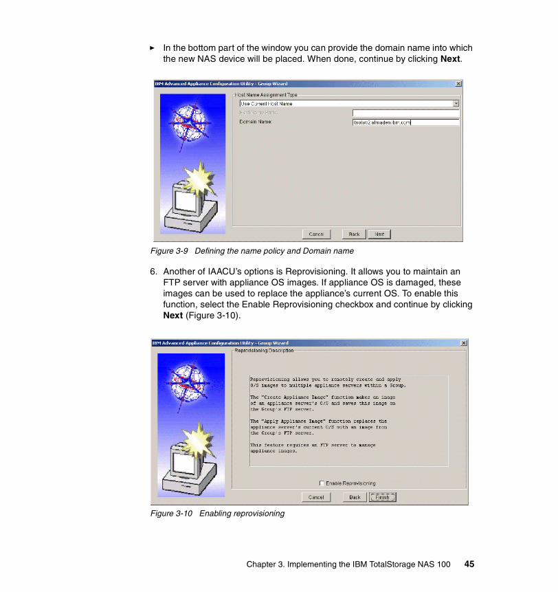
� In the bottom part of the window you can provide the domain name into which the new NAS device will be placed. When done, continue by clicking Next.
Figure 3-9 Defining the name policy and Domain name
6. Another of IAACU’s options is Reprovisioning. It allows you to maintain an FTP server with appliance OS images. If appliance OS is damaged, these images can be used to replace the appliance’s current OS. To enable this function, select the Enable Reprovisioning checkbox and continue by clicking Next (Figure 3-10).
Figure 3-10 Enabling reprovisioning
Chapter 3. Implementing the IBM TotalStorage NAS 100 45

7. Click Finish to create the group. You can see that the NAS 100 device has been moved to the New Group. The first available IP address of the specified range for this group has been assigned to it (Figure 3-11).
Figure 3-11 NAS Appliance with network seetings applied
3.2 Configuration and administration toolsAfter you set up the networking parameters either with the Easy Setup or the IAACU, you can use the following tools to manage the NAS device:
� Universal Manageability Services (via a browser using port 1411)� Terminal Service Client� Web GUI interface (Windows Powered Server Appliance Tasks)
3.2.1 Universal Manageability ServicesUniversal Manageability Services (UM Services) is a Windows application that acts as both a stand-alone management tool for the system it is installed on, and a client to IBM Director. As a Director client, it receives and sends information to the Director Server as controlled from the IBM Director console. As a stand-alone tool, it provides a Web-browser based interface and a Microsoft Management Console (MMC) interface, where you can view the system status, perform certain management tasks, and configure alerts.
46 The IBM TotalStorage NAS 100 Integration Guide

UM Services is a lightweight client that resides on each managed computer system. It comes preinstalled on all IBM NAS appliances.
You can start UM Services to manage the NAS 100 appliance either from the IAACU by clicking the Start Web Management button (Figure 3-11 on page 46), or directly by opening the browser with the appliance’s IP address and port 1411 specified.
As a prerequisite for your Web browser interface, you must use Microsoft Internet Explorer version 5.1 or higher. If it was not previously installed, you also need to install Swing/JFC and XML Java libraries on your system (Figure 3-12).
Figure 3-12 UM services Java Library installation
Note: At some points in the documentation UM Services is referred to as the IBM Director Agent. For more information, refer to see 5.1, “IBM Director description” on page 108.
Chapter 3. Implementing the IBM TotalStorage NAS 100 47
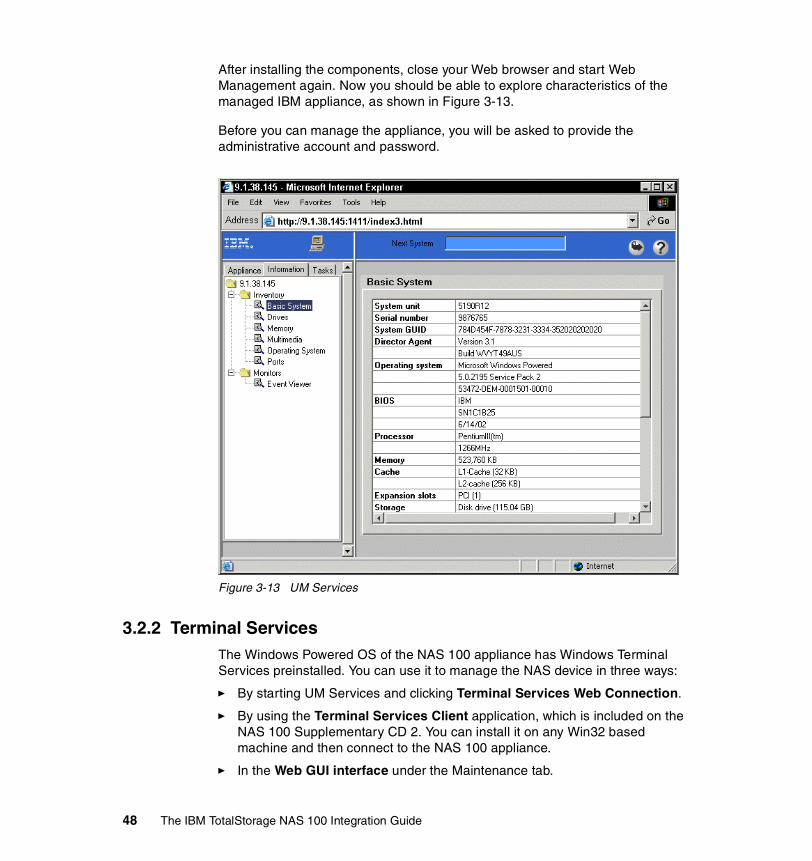
After installing the components, close your Web browser and start Web Management again. Now you should be able to explore characteristics of the managed IBM appliance, as shown in Figure 3-13.
Before you can manage the appliance, you will be asked to provide the administrative account and password.
Figure 3-13 UM Services
3.2.2 Terminal ServicesThe Windows Powered OS of the NAS 100 appliance has Windows Terminal Services preinstalled. You can use it to manage the NAS device in three ways:
� By starting UM Services and clicking Terminal Services Web Connection.
� By using the Terminal Services Client application, which is included on the NAS 100 Supplementary CD 2. You can install it on any Win32 based machine and then connect to the NAS 100 appliance.
� In the Web GUI interface under the Maintenance tab.
48 The IBM TotalStorage NAS 100 Integration Guide

Terminal Services Web Connection (through UM Services)Start your browser and enter the IP address or host name of the NAS 100 appliance, followed by port 1411:
http://YourIpAdressAppliance:1411
You will be asked to provide the administrator user name and password, as shown in Figure 3-14:
Figure 3-14 UM services Logon
Chapter 3. Implementing the IBM TotalStorage NAS 100 49

When the UM Services management interface opens, select Terminal Services on the Appliance tab in the left pane, as shown in Figure 3-15.
Figure 3-15 Using Terminal Services Web Connection
The Terminal Services Web Connection will open inside the browser window. You can now work with the NAS 100 appliance, as you will be logged on a local console. See Figure 3-16.
50 The IBM TotalStorage NAS 100 Integration Guide

Figure 3-16 Using Terminal Services Web Connection
Terminal Services ClientTerminal Services Client application is included on the NAS 100 Supplementary CD 2 (in the \Terminal Services Client\Disk 1 directory). You can install it by running the Setup.exe program on any Win32 based machine from which you want to remotely control the NAS 100 appliance.
To start it, click Start —> Programs —> Terminal Services Client and click the Terminal Services Client application. A window will open asking you to enter the Server name or IP address of the appliance you are connecting to. You will also be able to select the screen area in which the target desktop will be presented. A sample connection window is shown in Figure 3-17.
Chapter 3. Implementing the IBM TotalStorage NAS 100 51

Figure 3-17 Starting Terminal Services Client
3.2.3 Web GUI interfaceFor administrators who are not familiar with Windows operating systems, the NAS 100 provides a Web-based GUI, also referred to as Microsoft Windows Powered Server Appliance Tasks. Using a browser, you navigate through various administrative task categories. To select a particular management category, you simply click the appropriate button in the upper part of the browser window, and by clicking a link in that panel, you select a task from that category.
As we mentioned before, all administration tasks only work using Microsoft Internet Explorer 5.x or higher. In order to get access to a NAS appliance, type the following URL:
http://YourIpAddressAppliance:8099
Use an IP address that matches your NAS unit for “YourIpAddressAppliance”. The TCP/IP socket that is used for NAS is port 8099. After executing the URL, the system will prompt you for the username and password. After a successful login, you will see the Web interface shown in Figure 3-18.
52 The IBM TotalStorage NAS 100 Integration Guide

Figure 3-18 Web GUI interface
The main panels are listed below:
� Welcome panel� NAS Utilities� Status� Network� Disks� Users� Shares� Maintenance� Controller� Easy Setup� Help
Different panels and their corresponding tasks are described in detail in following chapters.
Chapter 3. Implementing the IBM TotalStorage NAS 100 53
3.3 NAS Setup Navigator overviewThe NAS Setup Navigator is an online help tool and it was created to assist you in setting up your IBM TotalStorage NAS appliance. It appears as an icon on the desktop of all the NAS appliances. The easiest way to use this tool is to follow the screens in the order presented. Should a question arise during the installation of your NAS appliance, you can refer to other sections in this chapter which describe in detail how to perform a specific task. Also, at the bottom of many of the navigator screens are links with additional information.
To use the NAS Setup Navigator, you need to connect to the NAS 100 appliance remotely by using Microsoft Terminal Services Client, or you can use the Web GUI interface and then Terminal Services.
You can use either the Easy Setup or the IAACU tool described in 3.4.1, “Basic configuration” on page 55 to supply an IP address to the NAS device for remote connectivity.
NAS Setup Navigator can assist you in accomplishing many tasks. These are the navigator screens:
� Information and Setup Options� Configuration Prerequisites� System Language� Administrator Password� Date and Time� Network Identification� Public LAN Settings� Configure Pooled Storage� Creating Partitions� Verifying Disk Health� Services for UNIX� Setting up Server for NFS� Setting up Gateway for NFS� Server for PCNFS� Configuring User Name Mapping� User and Security Management� Setting Up Windows Users and Groups� Sharing Pooled Storage� Configuring File Shares for Windows clients� Configuring File Shares for UNIX clients
As you can see, the NAS Setup Navigator can aid in the setup of your NAS appliance. In the following section we show you how to use the Navigator to configure an IBM TotalStorage NAS 100.
54 The IBM TotalStorage NAS 100 Integration Guide

3.4 Using the Navigator to set up the NAS 100In this section we demonstrate how to use the NAS Setup Navigator to set up the IBM TotalStorage NAS 100. As mentioned before, the wizard guides you through each step. Many of the NAS Setup Navigator screens have links in them that open additional configuration screens to make the process easier. To set up the NAS 100, follow these steps.
3.4.1 Basic configurationThese are the steps for basic configuration:
1. Connect to the NAS 100 appliance using any of the Terminal Services methods explained in 3.2.2, “Terminal Services” on page 48 and logon with an administrative account (default is Administrator and password).
2. Open the NAS Setup Navigator. The icon is located on the desktop of the IBM TotalStorage NAS appliance. The Getting Started screen appears first and explains the navigator. To advance, click the Forward button, which brings you to the Information and Setup Options screen, as shown in Figure 3-19.
Figure 3-19 NAS Setup Navigator — Information and Setup Options screen
Note: Checking the NFS box will result in bringing up screens later on in the wizard process for installing support for NFS.
Chapter 3. Implementing the IBM TotalStorage NAS 100 55

3. Select the Network File System box if support for NFS is required; otherwise, leave it unchecked and click Apply.
Clicking the Apply button will refresh the screen and bring you back to the top of the Information and Setup Options screen.
4. Click the Forward button. This will bring up the Configuration Prerequisites page. This is an information only screen and is here to help you gather and record information concerning the NAS appliance. When you are finished you can click the Forward button.
Figure 3-20 NAS Setup Navigator — additional screen
5. After the Configuration Prerequisites screen, the next set of NAS Setup Navigator screens will guide you through setting up some General Settings for your NAS appliance. Follow the steps and screens and configure the NAS appliance with the appropriate information for System Language, Administrator Password, and Date and Time. When you are done with each screen, click the Forward button to advance. A typical NAS Setup Navigator screen is shown in Figure 3-21.
Note: If the navigator screen has a link (which will be in a different color and underlined) and directs you to click it, a file download screen will come up as shown in Figure 3-20 and ask you to either open the file from the current location or save to disk. Always select the radio button, Open this file from its current location, and click OK. This will bring up a new Windows screen.
56 The IBM TotalStorage NAS 100 Integration Guide
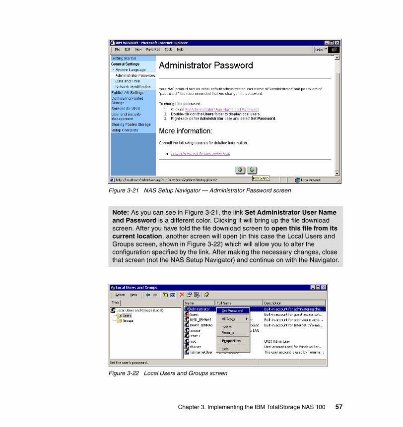
Figure 3-21 NAS Setup Navigator — Administrator Password screen
Figure 3-22 Local Users and Groups screen
Note: As you can see in Figure 3-21, the link Set Administrator User Name and Password is a different color. Clicking it will bring up the file download screen. After you have told the file download screen to open this file from its current location, another screen will open (in this case the Local Users and Groups screen, shown in Figure 3-22) which will allow you to alter the configuration specified by the link. After making the necessary changes, close that screen (not the NAS Setup Navigator) and continue on with the Navigator.
Chapter 3. Implementing the IBM TotalStorage NAS 100 57

6. Configure Network Identification on your NAS 100 by clicking the Network Identification link. This will bring up the system properties window. Click the Network Identification tab and then Properties. Now you have the option to join the NAS 100 appliance to your environment, as shown in Figure 3-23.
Figure 3-23 Network identification — Domain membership
7. If you want the NAS 100 to be a storage device for your workgroup, check Workgroup, and type in the name of your workgroup. Be aware that all security management within such a workgroup is local. This means you have to administer all user accounts on the NAS 100. Also be aware that the default behavior when sharing a network drive with Windows is to grant all users full access to the data.
8. If you want the NAS 100 to be part of a domain, then check domain and enter the name of the domain you would like to join. A popup window will ask for the username and password of a domain administrator or equivalent. Either way, when you are finished, click the OK button. A reboot is required.
9. You will now continue with the NAS Setup Navigator by configuring Public LAN settings. Configure your IBM TotalStorage NAS appliance with the appropriate information for Public LAN Settings by clicking the Network and Dial-up Connections link. This will bring up the Network and Dial-up Connections window as shown in Figure 3-24.
10.Right-click the connection you want to work with and choose Properties.
58 The IBM TotalStorage NAS 100 Integration Guide

Figure 3-24 Network configuration window
11.Highlight Internet Protocol (TCP/IP), then click Properties. Now you will see the TCP/IP protocol configuration screen (Figure 3-25).
Figure 3-25 IP Properties screen
Chapter 3. Implementing the IBM TotalStorage NAS 100 59

12.Our example shows an IP address of 9.1.38.144. Configure the IP address and settings for your network. You should get the information from your network administrator:
– IP address– Subnet Mask– Default Gateway– Preferred DNS Server– DNS Suffix
The DNS Suffix and WINS, etc., can be found under the Advanced tab. When you are finished configuring your network adapters, click the OK button and exit back to the NAS Setup Navigator. Click the Forward button to configure your drives.
3.4.2 Storage configuration and managementThe NAS 100 comes with storage space already configured. Four hard drives are connected to the on board ATA controller and the NAS 100 is using the Windows 2000 integrated software RAID function. Hard drive storage space is configured as follows:
� A mirrored volume on HDD1 and HDD2 for the System volume (drive letter will be C:)
� A mirrored volume on HDD3 and HDD4, for the Recovery system volume (driveletter will be D:)
� A RAID-level 5 volume, comprised of the remaining storage on HDD1, HDD2, HDD3, and HDD4 (drive letter will be E:)
Data volume (drive letter E:) comes preconfigured and ready to use. If, for any reason, you want to reconfigure it, you can do so by following directions in the Configure Pooled Storage screen of the NAS Setup Navigator. By clicking the Disk Management link in the Creating Partitions panel (shown in Figure 3-26), the Disk Management snap-in will start and you have the possibility to delete, create new partitions, or verify existing partitions.
Note: The NAS 100 comes preconfigured, and you may be able to skip these steps if the factory default settings meet your business needs.
Important: Although usable disk space is available on the System and Recovery volumes, it is not recommended to repartition them. NAS 100 System Recovery will not function if the System volume configuration is changed.
60 The IBM TotalStorage NAS 100 Integration Guide
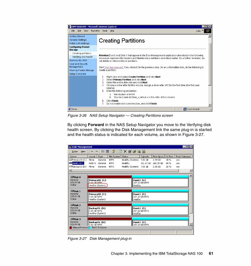
Figure 3-26 NAS Setup Navigator — Creating Partitions screen
By clicking Forward in the NAS Setup Navigator you move to the Verifying disk health screen. By clicking the Disk Management link the same plug-in is started and the health status is indicated for each volume, as shown in Figure 3-27.
Figure 3-27 Disk Management plug-in
Chapter 3. Implementing the IBM TotalStorage NAS 100 61

Disk subsystems managementUnlike the NAS 200 and NAS 300 appliances, the NAS 100 device doesn’t use a hardware based RAID controller and there are no specific management applications for the disk subsystem. NAS 100 employes industry-standard management tools included in Windows Powered for NAS operating system, meaning the Microsoft Management Console. Specifically, the Disk Management plug-in can and should be used for all disk-related management tasks.
3.4.3 Microsoft Services for UNIXAs part of the initial preload, the Microsoft Services for UNIX v2.2 provide file access to UNIX and UNIX-based clients and servers using Network File System (NFS) protocol. In this section you can:
� Set up the Server for NFS.� Set up the Gateway for NFS.� Configure the Server for PCNFS.� Configure User Name Mapping.
Each of this tasks can be started separately by choosing the corresponding link in the left pane, or they can be accomplished one after another by clicking the Forward buttons. Selecting the links in the center of this screen will open a comprehensive Microsoft Services for the UNIX online help library (Figure 3-28).
Figure 3-28 NAS Setup Navigator — Services for UNIX
62 The IBM TotalStorage NAS 100 Integration Guide

UNIX Network Information System (NIS) integrationThe UNIX Network Information System (NIS) services work like using the yellow pages. While the NAS 100’s feature set includes support for NIS, the security standard of NIS is not very high. Therefore we do not recommend the use of NIS with this product.
Within Microsoft Services for UNIX v2.2 there is a NIS migration wizard. This tool allows you to migrate a NIS. The tool takes your NIS source files and migrates them into Active Directory.
The Server for NIS feature allows a Windows Domain controller to be an NIS master server or an NIS subordinate (slave) by integrating NIS into Active Directory. When using the NIS server as a slave, the NIS master server must be a Windows 2000 Server.
For more information, you can check the following Web site:
http://www.microsoft.com/WINDOWS2000/sfu/default.asp
Password synchronizationAnother tool that is included within the Microsoft Services for UNIX 2.2 is a password synchronization tool (2-way). It allows you to synchronize password changes between Windows NT or Windows 2000 and UNIX. Pre-compiled single sign-on daemons are available for:
� IBM AIX 4.3+� Linux (Red Hat 5.2, 6.0, 7.x, 8.0)� Sun Solaris 2.6+� HP-UX 10.3+� Compaq Tru64 UNIX
For a detailed overview and functional explanation of Services for UNIX, see Chapter 6, “Cross platform storage” on page 171.
3.4.4 User and security managementThis section describes integrating the NAS 100 into a secure environment. The NAS 100 appliance is designed to plug right into your existing user and security management system.
Note: Even if your UNIX version is not on the list — it may still work. Microsoft provides the source code for the password synchronization tool.
Chapter 3. Implementing the IBM TotalStorage NAS 100 63

Active Directory, NT 4 Domains, and WorkgroupsThe NAS 100 will integrate with all of the Microsoft Operating System versions that you may have in your current network environment. It will work with any existing user and security management for those systems, including:
� Windows Workgroup Computing� Windows NT 4 Domains� Windows 2000 Active Directory (mixed and native mode)
Fully describing user and security management for Windows is beyond the scope of this book, so we will just provide you with a quick overview. A more detailed look at Active Directory is provided within Chapter 10 of the IBM Redbook, The IBM TotalStorage NAS Integration Guide, SG24-6505-01. This book can be found at:
http://publib-b.boulder.ibm.com/Redbooks.nsf/RedbookAbstracts/sg246505.html?Open
Also, you can refer to the literature regarding Microsoft Operating Systems. Some examples are listed in “Related publications” on page 319.
To manage local users on your NAS 100, from the NAS Setup Navigator left pane, select the User and Security Management section (Figure 3-29).
Figure 3-29 NAS Setup Navigator — Setting Up Windows Users and Groups
64 The IBM TotalStorage NAS 100 Integration Guide

On the screen, Setting Up Windows Users and Groups, click the link, Set Up Windows Users and Groups, and the Local Users and Groups plug-in will start in a separate window. To create a new user, click Action —> New User, and enter the User name and password for the new user (Figure 3-30).
Figure 3-30 Local Users and Groups plug-in
The same tool can be used for creating a new local group on the NAS 100 appliance.
To give users from any domain access to the storage resources on the NAS 100 appliance, you have to move the device into the domain first. This can be done as part of the Network Identification procedure. It is shown in Figure 3-23 on page 58.
When you want to join an existing Windows NT 4.0 Domain, check the Domain box and type in the name of your domain. Press OK to confirm your choice and you will soon be a happy member of an existing Windows NT 4.0 Domain.
Joining an Active Directory tree is almost identical to joining an NT 4 Domain. Check Domain and type in the name of your Active Directory tree.
Tip: When joining an existing NT 4 Domain across subnets or via routed paths, define the PDC as the primary WINS server, even if the WINS service is not running on the PDC. This way, the joining client will find the PDC easily.
Important: When joining an Active Directory, it is essential that your TCP/IP configuration and DNS name resolution be working properly. Make sure both machines can ping each other using the IP address and the fully qualified domain name before joining the domain. For example, type:
ping lochness.itsolab2.almaden.ibm.com
Chapter 3. Implementing the IBM TotalStorage NAS 100 65

3.4.5 Sharing pooled storageAs the last step of the NAS Setup Navigator we have to share the NAS 100 storage space to the users in the network. IBM TotalStorage NAS 100 appliance supports multiple network protocols used in different client operating systems, including:
� CIFS (NT LM 0.12) for Windows clients� NFS (v2.0, v3.0) for UNIX clients� FTP� HTTP (v1.1)� Apple File Protocol� Netware (Novell 4,5,6 via Windows Services for Netware V5.0)
Sharing for Windows clients using the CIFS protocolTo get information about sharing folders on the NAS 100 device, read the directions in the File Sharing for Windows clients screen of the NAS Setup Navigator. Then click the Windows Explorer link, as shown in Figure 3-31.
Figure 3-31 NAS Setup Navigator — File Sharing for Windows Clients
66 The IBM TotalStorage NAS 100 Integration Guide
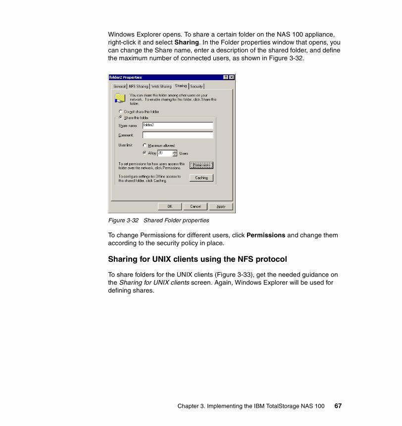
Windows Explorer opens. To share a certain folder on the NAS 100 appliance, right-click it and select Sharing. In the Folder properties window that opens, you can change the Share name, enter a description of the shared folder, and define the maximum number of connected users, as shown in Figure 3-32.
Figure 3-32 Shared Folder properties
To change Permissions for different users, click Permissions and change them according to the security policy in place.
Sharing for UNIX clients using the NFS protocol
To share folders for the UNIX clients (Figure 3-33), get the needed guidance on the Sharing for UNIX clients screen. Again, Windows Explorer will be used for defining shares.
Chapter 3. Implementing the IBM TotalStorage NAS 100 67

Figure 3-33 NAS Setup Navigator — File Sharing for UNIX clients
3.4.6 Completing setupThis concludes the setup of the NAS 100 appliance using the NAS Setup Navigator. You can return to any of the available sections at any time to view or change some of the settings mentioned (Figure 3-34).
Figure 3-34 NAS Setup Navigator — Setup Complete
68 The IBM TotalStorage NAS 100 Integration Guide

Chapter 4. Advanced NAS configuration
In this chapter we provide a detailed description of tools and procedures for advanced configuration of your IBM TotalStorage NAS 100.
We cover these topics:
� Quota management� Persistent Storage Manager (PSM)� Ethernet adapter teaming� Uninterrupted Power Supply support
4
© Copyright IBM Corp. 2003. All rights reserved. 69
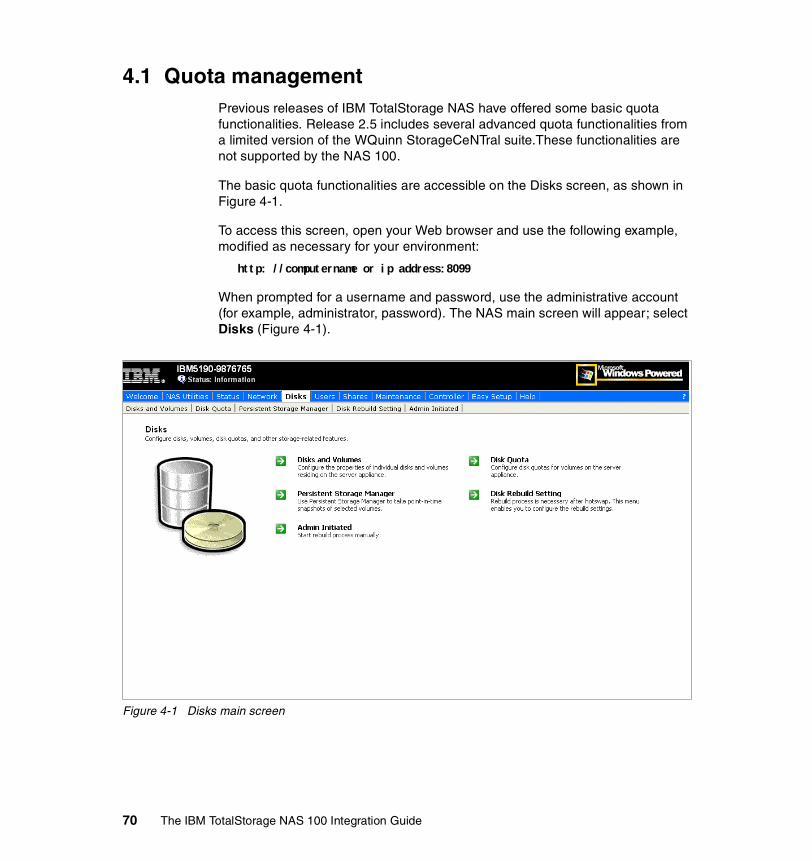
4.1 Quota managementPrevious releases of IBM TotalStorage NAS have offered some basic quota functionalities. Release 2.5 includes several advanced quota functionalities from a limited version of the WQuinn StorageCeNTral suite.These functionalities are not supported by the NAS 100.
The basic quota functionalities are accessible on the Disks screen, as shown in Figure 4-1.
To access this screen, open your Web browser and use the following example, modified as necessary for your environment:
http: //computername or ip address:8099
When prompted for a username and password, use the administrative account (for example, administrator, password). The NAS main screen will appear; select Disks (Figure 4-1).
Figure 4-1 Disks main screen
70 The IBM TotalStorage NAS 100 Integration Guide

4.1.1 Disk quotasThe following steps allow you to set up disk quotas on the NAS devices:
1. Click Disk Quota in the Disks Main screen shown in Figure 4-1.
2. You get the Disk Quota screen (Figure 4-2) where you can select a volume to define disk quotas:
– On a per-volume basis (click Quota)– On a per-user basis (click Quota Entries)
Figure 4-2 Disk Quota screen
Chapter 4. Advanced NAS configuration 71

3. Click Quota to set all quota parameters for a volume, as shown in Figure 4-3.
Figure 4-3 Disk Quota settings screen
4. When finished, click OK to get back to the Disk Quota screen.
72 The IBM TotalStorage NAS 100 Integration Guide

5. Click Quota Entries to get the Quota Entries for the selected volume screen (Figure 4-4).
Figure 4-4 Quota Entries screen
Chapter 4. Advanced NAS configuration 73

6. Click New to get the New Quota Entry screen (Figure 4-5) to create a quota for a user in the selected volume. Configure the settings and click OK.
Figure 4-5 New Quota Entry screen
74 The IBM TotalStorage NAS 100 Integration Guide

7. Now you get back to the Quota Entries screen that shows the new user quota (Figure 4-6).
Figure 4-6 Quota Entries screen
Click Back —> Back to get back to Disk Main screen (Figure 4-1 on page 70).
4.2 Persistent Storage Manager (PSM)Persistent Storage Manager (PSM) is a utility that creates point-in-time images of the file system on the NAS unit.
This is done by using a copy-on-write technique that uses, for each volume, an area of pre-allocated storage (the PSM cache file) that keeps only those data blocks which have been written since the time you made a persistent image of the volume.
Chapter 4. Advanced NAS configuration 75

This image then can be used to restore accidentally deleted files or corrupted data, or even to back up data to another location (disk or tape). Also, this image is sometimes called Persistent True Image (PTI), because it is:
� Persistent: Images survive accidental or intentional reboots, file corruption, and system crashes, and are highly resistant to virus attacks.
� True Image: Data is managed at the block level of the device, even though files and folders are presented to the users.
PSM is preloaded in the IBM TotalStorage NAS devices.
PSM’s most important function is its capability to create a True Image (other terms are point-in-time image, snapshot) of open files, thus eliminating the necessity to shut down applications. It does this using its component called Open Transaction Manager (OTM). With point-in-time images, you can run your backup while the system I/O continues.
4.2.1 How PSM worksPSM runs and operates below the file system as a storage filter class driver, intercepting all write actions to the NAS volumes.
When the command to create a True Image is executed, PSM begins monitoring the file system looking for a quiescent period. The quiescent period provides sufficient time for completion of writes and for the various software buffers to flush.
The premise is that, by the end of the quiescent period, a volume will be created which is in a “stable” state. This means that the volume is at rest, the caches has been flushed, and the data is consistent.
If the volume is captured in a “stable” state, then all its contents (files and folders) can be returned to a “usable condition” for user access. If quiescence is not achieved within the allocated period, the True Image will not be created
Following the quiescent period, PSM creates the persistent True Image, a virtual point-in-time representation of the volume. This True Image is presented in folders and files structure in exactly the same manner as they are presented on the source volume (see Figure 4-18 on page 88). Metaphorically, the True Image contains the data that was overwritten on the live volume from the time of the previous True Image creation to the creation of the current True Image.
In reality, at the time of True Image creation, PSM sets up junction points, to the Diff Data maintained in the PSM area. The actual creation of the True Image requires minimal resources and time.
76 The IBM TotalStorage NAS 100 Integration Guide

Writing to a PSM NAS volumeWhen a write I/O is sent to the production volume after a True Image has been created, PSM intercepts and pauses the request, reads the data (or the blocks) that is to be overwritten, and saves the data in a Diff directory within the PSM-specific cache file. After the original data has been copied to the cache, PSM releases the new data and it is written to the live (production) volume. This process is called “copy-on-write”. It is shown in Figure 4-7.
Figure 4-7 PMS’s copy-on-write process
Reading a True ImageTrue Images may consist of data on both the active volume and PSM cache. If this is the case, and there is a requirement to read the True Image (for backup purpose or data retrieval), PSM determines whether data has changed (data is now on the PSM cache) or is still unchanged on the active volume. Then PSM retrieves the data accordingly (whether on PSM cache or active volume) and presents it to the user. See Figure 4-8 for the process flow.
b
b
Network
PSM
DiskStorage
PSM Cache
1
2
34
1. Write request comes in from the network.2. PSM intercepts and pauses write, then copies old data from active volume.3. Old data is written to PSM cache.4. New data is written to active volume.
Chapter 4. Advanced NAS configuration 77

Figure 4-8 Process flow of reading a True Image
Processes such as backup or restore having access through a persistent image, have a lower priority than normal read and write operations. Therefore, if the NAS device is experiencing heavy client utilization, and at the same time a backup program is launched to access the True Image, the latter will have lesser priority for minimal performance impact.
While creating the PSM images happens very quickly, it may take a few minutes before that image is visible and available to the users. Generally, the very first image will take much longer to create than subsequent images.
Performance impact of PSMThe performance considerations for PSM can be subdivided into write performance and read performance.
b DiskStorage
PSM Cache
3
2
1. PTI read request comes in from the network.2. PSM determines if data is stored on active volume or PSM cache, then combines them.3. PSM presents the PTI to the user.
Network
PSM
1
2
78 The IBM TotalStorage NAS 100 Integration Guide

Write performancePSM creates minimal additional I/O overhead which is limited to writes. The copy-on-write process adds one read (the write is paused to read the old data from the live volume) and one write (old data is copied to PSM cache) to each write system request.
Read performanceReads are merely affected, since typically 90% of all I/O activities are reads directly from the live volume, which causes no interaction with PSM. However, when access to True Images is required (backup, prototypes, compatibility testing), this causes interaction with PSM for data retrieval from live volume, PSM cache, or both. This, as discussed earlier, has a lower priority.
4.2.2 Creating images with PSMTo access the PSM functions, you need to get connected to the NAS system via Web interface as seen in the next steps:
1. Open your Internet Explorer (you may also connect by using Terminal Services or locally) and use the following example, modified for your environment:
http: //computername or ip address:8099
2. When prompted for a username and password, use the administrative account (for example, administrator, password).
Note: PSM is designed for the main purpose of quick data retrieval, as well as creating readily available images for other functions (such as backup and development testing) even with open files (no need for application shutdown). Although it can be used for backup purposes, backup performance is not an issue PSM was designed to address.
Chapter 4. Advanced NAS configuration 79

3. The NAS main screen will appear, as shown in Figure 4-9.
Figure 4-9 Microsoft Windows 2000 for NAS main screen
80 The IBM TotalStorage NAS 100 Integration Guide

4. From the main screen, select Disks (Figure 4-10).
Figure 4-10 Disks screen
5. Select Persistent Storage Manager and you will see the screen shown in Figure 4-11.
Figure 4-11 PSM main screen
Now you are in the PSM main screen ready to configure PSM.
Chapter 4. Advanced NAS configuration 81

4.2.3 Configuring PSMBefore you create images, you need to configure PSM first. The following steps are intended to guide you through the PSM configuration:
1. Configure the Global settings. From the PSM main screen, click Global Settings (see Figure 4-12).
Figure 4-12 PSM Global Settings screen
This is where you can set the PSM Global Settings:
– Maximum persistent images:
This corresponds to the maximum number of active images that you can create per volume.
The default value is 250.
– Inactive period:
This is the idle time (on the volume) PSM will wait before creating a persistent image.
The default value is 5 seconds.
82 The IBM TotalStorage NAS 100 Integration Guide

– Inactive time-out:
This is the time that PSM will wait for inactivity. If the Inactive period (for example, 5 seconds) does not occur within the specified Inactive time-out (for example, 15 minutes), PSM will not create a persistent image.
The default value is 15 minutes.
– Persistent image directory name:
This is the name of the directory that will contain the image of your volume. The default here is “snapshot”, but you can change it to any name you want.
The default directory is snapshot.
When finished, click OK to get back to the PSM main screen.
2. Configuring the Volume settings. Click Volume Settings:
This is where you can configure the specific volume attributes (see Figure 4-13).
Figure 4-13 PSM Volume Settings screen
You can select a volume and configure the specific attributes by clicking Configure (see Figure 4-14).
Chapter 4. Advanced NAS configuration 83

Figure 4-14 PSM attributes of a volume
– Warning threshold:
This is the percentage of the cache size before warnings are sent. This is done to inform the NAS administrator that it is time to save the images before unwanted deletion of the first persistent images occurs. The logs for this option are saved in the Windows Event Log, so you can check for it using either Internet Explorer or a Terminal Services Client.
The default value is Cache 80% Full.
– Begin deleting images:
This is the percentage of cache size that, if reached, will begin deleting images on first in first out basis
The default value is Cache 90% Full.
– Cache size:
This is the size of the PSM cache allocated from the PSM volume location. Is expressed in a percentage of the volume size. Make sure that you have enough space in you volume to hold the cache file.
The default value is 15%.
84 The IBM TotalStorage NAS 100 Integration Guide
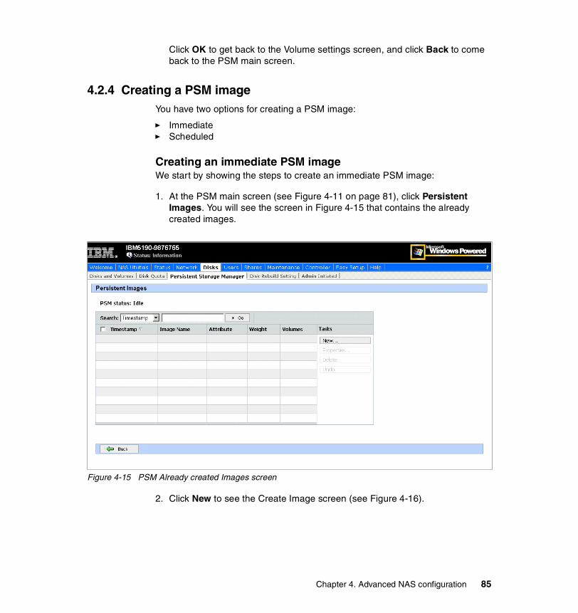
Click OK to get back to the Volume settings screen, and click Back to come back to the PSM main screen.
4.2.4 Creating a PSM imageYou have two options for creating a PSM image:
� Immediate� Scheduled
Creating an immediate PSM imageWe start by showing the steps to create an immediate PSM image:
1. At the PSM main screen (see Figure 4-11 on page 81), click Persistent Images. You will see the screen in Figure 4-15 that contains the already created images.
Figure 4-15 PSM Already created Images screen
2. Click New to see the Create Image screen (see Figure 4-16).
Chapter 4. Advanced NAS configuration 85

Figure 4-16 Create Image screen
3. In the Volumes to Include:, select the drives that you want to create an image of. For multiple volumes, press the Ctrl or Shift key while selecting the drives you want to have PSM images created of.
4. You can choose if the image has read-only attributes or if it read/write.
5. You can also give the image a relative retention weight and a name. The retention weight is important when PSM needs to delete some persistent images of a volume because the cache file for the volume has reached a certain threshold.
6. Click OK. You will be taken to the Persistent Image List window showing the volumes.
Note: After PSM images are created, you might have to wait for a few seconds or minutes in order for PSM to update its write-back queues and caches. In particular, the very first image will generally take much longer than subsequent images. Hence, if the system is heavily utilized, this update may take a while. After this, you should be able to access the images. One other thing to keep in mind is that — by design — PSM will run at a lower priority than regular I/O.
86 The IBM TotalStorage NAS 100 Integration Guide

7. After a while, click the Refresh icon on your Internet Explorer. You should now see the new images you created on the list (Figure 4-17). You can change the properties, undo changes made to the image, or delete the image using this screen.
Figure 4-17 Persistent Image List screen
8. To check if the images contain exactly the same data as the volumes you selected, logon to the NAS using Terminal Services Client from the Maintenance menu on your Web Browser (or do it locally).
9. After that, open a Windows Explorer window.
As shown in Figure 4-18, a snapshot directory has been created on each volume (E:) that was selected during the image creation. The mounted volumes in turn contain the directories (and files) that were in each volume at the time you created the images.
Chapter 4. Advanced NAS configuration 87

Figure 4-18 Screen showing the image created
Creating scheduled PSM imagesAn automated version of creating a PSM image is also available. You can schedule your job tasks so that those actions can take place during the night and after business hours. The following steps demonstrate how to create a scheduled PSM image:
1. From the PSM main screen, select Schedules (Figure 4-11 on page 81).
2. On the Persistent Image Schedules screen, click New.
88 The IBM TotalStorage NAS 100 Integration Guide

3. On the Create Persistent Image Schedules screen (Figure 4-19), select the entries for the following by clicking the pull-down arrow.
– Start at: – Repeat Every: – Begin: – Volumes to Include:– Image Attributes:– Retention Weight:– Number of images to save:– Image name:
Figure 4-19 Screen for creating a new scheduled persistent image
4. Click OK.
5. You reach the Scheduled Persistent Images window showing the volumes, time and date, and repetition you selected earlier (Figure 4-20). In this screen you can also change the properties of the scheduled Image or delete it.
Chapter 4. Advanced NAS configuration 89

Figure 4-20 Screen showing scheduled persistent images
4.2.5 Restoring a Persistent ImageIf you need to use the information stored in an image, you have two choices:
� File system access � Restore the complete image
File System AccessYou can access the files stored in the Persistent Images just as any other file in your system. See Figure 4-21.
1. Open the Windows Explorer.
2. Go to the Persistent Images directory (snapshot in our example).
3. Choose the image you want to use (snapshot.1 in our example).
4. Choose and work with the file as usual, browsing with the Windows Explorer and finding the file.
5. You can now do the following:
a. Drag-and-drop it on to the volume to replace the actual file.
b. Edit the file directly, if the image was created as read/write.
90 The IBM TotalStorage NAS 100 Integration Guide

c. Edit the file after copying it to the volume, if the image was created as read-only.
Figure 4-21 Using files in a Persistent Image
Restore the complete imageYou restore the complete volume image by clicking Restore Persistent Images in the PSM main screen.
1. In the Persistent Images to Restore Screen, you can choose the Image to be restored (see Figure 4-22):
a. Select the Image you want to restore.
b. Click Details to see more information.
c. Click Restore to restore the image.
Chapter 4. Advanced NAS configuration 91

Figure 4-22 Choose the Persistent Image to restore
2. Click OK in the confirmation screen.
Now you have successfully restored the Persistent Image.
4.2.6 Disaster Recovery with PSMIn the event that you need to recover the operating system volume from the Recovery CD all systems settings have to be recreated. PSM provides a procedure for backing up the system partition in a network share or local disk. This procedure also creates a boot diskette to boot the machine, and recovers the system partition from the image (unattended):
92 The IBM TotalStorage NAS 100 Integration Guide

1. To start the process, click Disaster Recovery in the PSM main screen. You are now in the Disaster Recovery screen (see Figure 4-23). This is an informative screen with the current status of the disaster recovery tool. You can start an immediate backup, create a boot diskette, or configure the properties.
Figure 4-23 PSM Disaster Recovery screen
Chapter 4. Advanced NAS configuration 93

2. Click Properties to configure the settings. Now you are in the PSM Disaster Recovery Properties screen, as shown in Figure 4-24.
Figure 4-24 PSM Disaster Recovery Properties screen
3. Now you provide the needed parameters, such as these:
– Location of backup (up to three sites, including network shares)
– Number of copies for each site
– Size limit for each site
– Settings for scheduling the command
– Backup name
– Username and password that attaches to the network shares during a system backup or disaster recovery
4. Now you can click OK and come back to the PSM Disaster Recovery screen.
– Click Start to start the backup.
– Click OK again in the confirmation screen.
94 The IBM TotalStorage NAS 100 Integration Guide

5. You can monitor the progress of the image creation in the PSM Disaster Recovery screen, as shown in Figure 4-25.
Figure 4-25 Backing up Disaster Recovery Image
Chapter 4. Advanced NAS configuration 95

6. When the image is copied, you can see the results in the PSM Disaster Recovery screen in Figure 4-26.
Figure 4-26 PSM Disaster Recovery Image created
7. You should now create the boot disk:
a. Insert a formatted floppy disk in a USB diskette drive connected to the NAS device. For more details you can see “Enabling USB support” on page 283 and “Boot” on page 285.
b. Click Create Disk in the PSM Disaster Recovery screen.
c. Click OK in the confirmation screen. This can take some time.
d. When finished click Back to get back to the PSM Disaster Recovery screen.
e. To make the disk bootable, run the fixboot.bat file on the floppy disk.
8. The process to recover the system volume from a disaster recovery image is straightforward. Just boot the NAS appliance with the boot diskette inserted. The recovery process starts automatically and will try the first given path that contains a valid image and load it. After that you only have to reboot the machine.
Note: A USB Floppy disk is not yet supported!
96 The IBM TotalStorage NAS 100 Integration Guide

4.3 Ethernet adapter teamingThis section describes how to enable adapter teaming on the Ethernet adapters of the NAS 100.
4.3.1 Overview of adapter teamingTeaming provides traffic load balancing and redundant adapter operation in the event that a network connection fails. NAS 100 has two Gigabit Ethernet adapters that can be grouped into teams. If traffic is not identified on any of the adapter team members’ connections due to failure of the adapter, cable, switch port, or switch (where the teamed adapters are attached to separate switches), the load distribution is reevaluated and reassigned among the remaining team members. In the event that all the primary adapters are down, the hot standby adapter becomes active. Existing sessions are maintained, causing no user impact. NAS 100 supports three schemes of load balancing:
� Smart load balancing� Link aggregation (802.3ad)� Generic link aggregation (Trunking)
Smart load balancingThe implementation of load balancing based on IP flow. This feature supports balancing IP traffic across multiple adapters (that is, team members). In this mode, all adapters in the team have separate MAC addresses. It provides automatic fault detection and dynamic failover to another team member or to a hot standby member; this is done independently of layer 3 protocol (IP, IPX, NetBEUI). It works with existing layer 2 and 3 switches.
Link aggregationThis mode supports link aggregation through static configuration and conforms to the IEEE 802.3ad specification. Configuration software allows you to statically configure which adapters you want to participate in a given team. If the link partner is not correctly configured for 802.3ad link configuration, you will receive errors. With this mode, all adapters in the team are configured to receive packets for the same MAC address.
Chapter 4. Advanced NAS configuration 97

Generic link aggregation (Trunking)This mode is very similar to 802.3ad in that all adapters in the team need to be configured to receive packets for the same MAC address. This mode supports a variety of environments where the link partners for the NICs are statically configured to support a proprietary trunking mechanism.
Basically, this mode is a light version of the 802.3ad link aggregation. This approach is much simpler because there is not a formalized link aggregation control protocol. As with the other modes, the creation of teams, and the allocation of physical adapters to various teams, is done statically with user configuration software.
Trunking supports load balancing and failover for both outbound and inbound traffic.
4.3.2 Load balancing for the configurationLoad Balance provides an easy way to configure the load balancing and redundant adapter function by grouping multiple adapters into teams.
The Load Balance panel allows you to configure advanced features. Teaming is a method of grouping multiple adapters into a virtual adapter (bundling multiple adapters to look like a single adapter). The benefit of this approach is load balancing.
To access the Ethernet Adapter Teaming tool, use the following sequence:
1. Open Control Panel via Remote Control or Terminal Services Session, Start -> Settings -> Control Panel.
2. Double-click the Broadcom NetXtreme Gigabit icon, to start the tool (Figure 4-27).
98 The IBM TotalStorage NAS 100 Integration Guide

Figure 4-27 Control Panel on NAS 100 with Broadcom NetXtreme Gigabit icon
3. The initial configuration panel will open (Figure 4-28).
Important: You must have a working DHCP Server in your network infrastructure. This is necessary because the Load Balance tool will disconnect the TCP/IP connection while configuring the new team (Figure 4-32 on page 103)! It is not possible to configure the IP-address before restarting the network! Make sure that the new ethernet team will get an IP address and is registered by the DNS server or Windows domain controller. You can connect to the NAS100 via terminal services or remote control after network has been restarted. Otherwise, you may lose connectivity to your NAS 100 system.
Chapter 4. Advanced NAS configuration 99

Figure 4-28 Initial configuration panel
100 The IBM TotalStorage NAS 100 Integration Guide
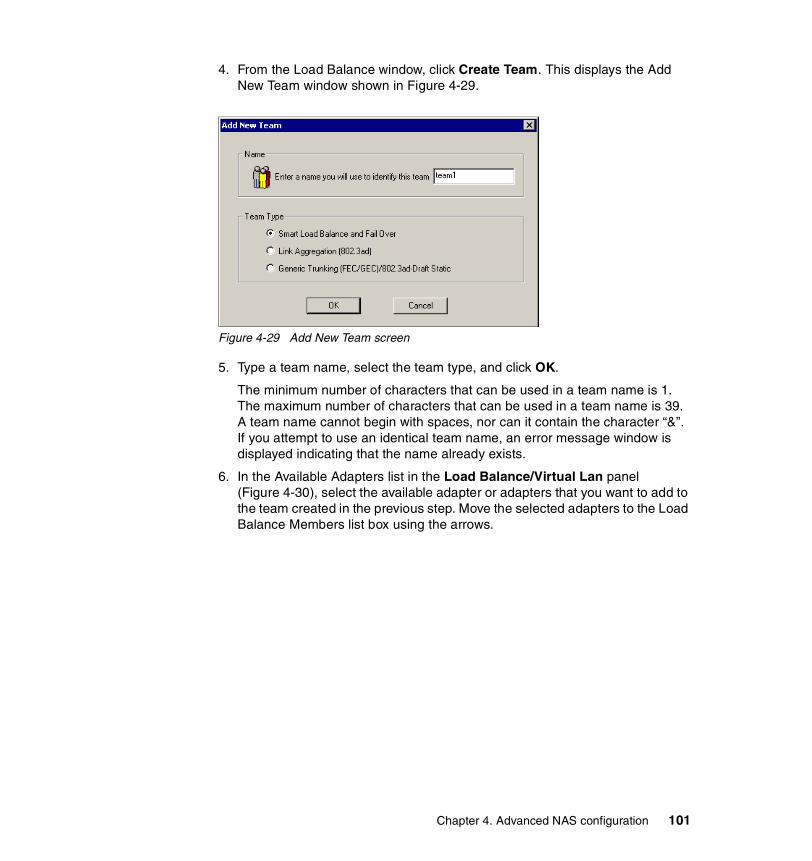
4. From the Load Balance window, click Create Team. This displays the Add New Team window shown in Figure 4-29.
Figure 4-29 Add New Team screen
5. Type a team name, select the team type, and click OK.
The minimum number of characters that can be used in a team name is 1. The maximum number of characters that can be used in a team name is 39. A team name cannot begin with spaces, nor can it contain the character “&”. If you attempt to use an identical team name, an error message window is displayed indicating that the name already exists.
6. In the Available Adapters list in the Load Balance/Virtual Lan panel (Figure 4-30), select the available adapter or adapters that you want to add to the team created in the previous step. Move the selected adapters to the Load Balance Members list box using the arrows.
Chapter 4. Advanced NAS configuration 101

Figure 4-30 Available adapters added to team
7. When you have finished configuring failover teams, click OK or Apply to accept the changes.
8. A Microsoft Digital Signature message will appear (Figure 4-31). The BASP Virtual Adapter was not yet certified with a digital signature from Microsoft. Press Yes to continue the installation process.
Note: At least one adapter must be displayed in the Load Balance list box
102 The IBM TotalStorage NAS 100 Integration Guide

Figure 4-31 Microsoft Digital Signature message
As mentioned earlier, you must have a working DHCP Server in your network infrastructure. This is necessary because the Load Balance tool will disconnect the TCP/IP connection while configuring the new team (Figure 4-32).
Figure 4-32 Network connection interruption
9. When team configuration has been correctly performed, one Virtual Team adapter driver will be created for each configured team.
When you create a generic trunking team, you cannot select a Standby Member. Standby Members work only with Smart Load Balance and Failover Teams.
10.Configure the Team IP address if necessary. If other adapters in your system use TCP/IP bindings, the TCP/IP Properties window will open.
Chapter 4. Advanced NAS configuration 103
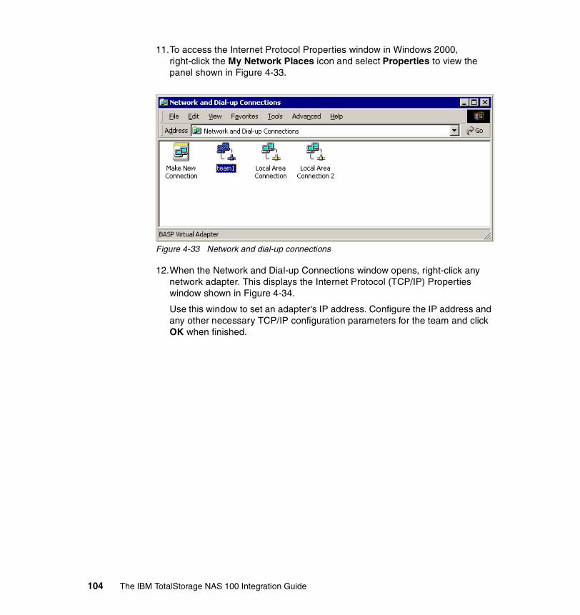
11.To access the Internet Protocol Properties window in Windows 2000, right-click the My Network Places icon and select Properties to view the panel shown in Figure 4-33.
Figure 4-33 Network and dial-up connections
12.When the Network and Dial-up Connections window opens, right-click any network adapter. This displays the Internet Protocol (TCP/IP) Properties window shown in Figure 4-34.
Use this window to set an adapter‘s IP address. Configure the IP address and any other necessary TCP/IP configuration parameters for the team and click OK when finished.
104 The IBM TotalStorage NAS 100 Integration Guide

Figure 4-34 TCP/IP configuration properties
4.4 Uninterrupted Power Supply supportIntegrated within the appliance is the support for IBM Uninterrupted Power Supplies (UPS). Uninterrupted power supply (UPS) provides emergency backup power for a specific period of time when the local power fails. This power comes from batteries housed within the UPS. High-performance surge suppression protects your server appliance from electrical noise and damaging power surges. During a power failure, the UPS instantly switches your NAS appliance to emergency battery backup power.
Once you have installed a UPS for your server appliance, you can set options for its operation using the UPS task on the Maintenance page of the NAS Admin tool. The UPS task enables you to control how the UPS service works on your NAS appliance. The available UPS settings depend on the specific UPS hardware installed on your system. See Figure 4-35.
Chapter 4. Advanced NAS configuration 105

Figure 4-35 UPS configuration screen
To ensure that the server appliance is protected from power failures, test it by simulating a power failure. Do this by disconnecting the main power supply from the UPS device. Your server appliance and peripherals connected to the UPS device should remain operational, messages should be displayed, and events should be logged. Wait until the UPS battery reaches a low level to verify that a graceful shutdown occurs. Restore the main power to the UPS device, and check the event log to verify that all actions were logged and there were no errors.
All detected power fluctuations and power failures are recorded in the event log, along with UPS service start failures and server shutdown initiations. Critical events may change the status of the server appliance.
106 The IBM TotalStorage NAS 100 Integration Guide

Chapter 5. Systems management for the NAS 100
Some of the systems management tools have already been described in this book, so in this chapter, we point out additional ones which can be used to manage the IBM TotalStorage NAS 100 appliances.
We cover these topics:
� IBM Director description� IBM Director Agent preload on NAS 100 appliance� Managing the NAS 100 appliance with IBM Director� How to install IBM NAS Extensions to IBM Director� Microsoft Multiple Device Manager (MDM)
5
© Copyright IBM Corp. 2003. All rights reserved. 107

5.1 IBM Director descriptionIn this section, we introduce IBM Director systems management solution. If you are already familiar with it you might want to skip the next pages and proceed directly to 5.3, “Managing the NAS 100 appliance with IBM Director” on page 111.
IBM Director (the current version is 3.1) is a powerful client/server workgroup manager, built on industry standards and designed for ease-of-use. It can leverage your existing enterprise or workgroup management environments to securely and efficiently access and manage physically dispersed IT assets. With IBM Director, IT administrators can view the hardware configuration of remote IBM and non-IBM systems in detail and monitor the usage and performance of critical components, such as processors, disks, memory and network subsystem. Advanced management capabilities, such as remote control, process management, event management and inventory are part of the solution.
IBM Director provides a convenient management user interface to execute tasks on specific systems or groups of systems. On the client side it uses a single, powerful agent which provides the client services to manage your systems intelligently. It supports systems management standards from legacy SNMP, to DMI and emerging CIM. A wide variety of clients running operating systems from Microsoft, Novell, IBM and the major Linux distributors, and an assortment of protocols including TCP/IP, IPX, SNA, NetBIOS, SLIP and HTTP can be used.
The three major components of IBM Director are the Director Server, Director Console, and Director Agent.
IBM Director Server is installed on a Windows NT 4.0 or Windows 2000 Server operating system in the managed environment. As the heart of IBM Director, the Director Server provides application logic and an up-to-the-minute data store of management information.
The IBM Director Server provides basic functionality through the following actions:
� Discovery of remote systems� Presence checking� Security and authentication� Management Console support� Support for each administrative task� Persistent store of inventory information, including operating system,
installed applications and hardware
108 The IBM TotalStorage NAS 100 Integration Guide

IBM Director includes Microsoft JET as its built-in SQL-compliant database, but can be installed with an existing database if needed. Microsoft SQL Server (6.5 or higher), IBM DB2 Universal Database version 5.2, and Oracle 7.5 are supported. As long as the Director Server is available, the information about the managed system will be available even if the client system in question is not responding.
IBM Director Console is a Java-based user interface from which administrative tasks are performed. The console provides comprehensive hardware management based on a single-click or drag-and-drop operation. All system specific data gathered by the Director Console is stored on the Director Server. The IBM Director Console can communicate with only one IBM Director Server at a time. Multiple Director Consoles, however, can be open at the same time, each communicating with the same or a different Director Server.
IBM Director Agent includes all of the code and interfaces needed on the managed systems. It can be used to manage the local system through a Web browser, through Microsoft Management Console or via IBM Director Console. In this case, it communicates with the Director Server, executes the queries and provides requested information. The Director Agent comes preloaded on all IBM TotalStorage NAS appliances.
Advanced systems management functionality is achieved via additional component: IBM Director Server Extensions. They work with the Advanced Systems Management Processor or other systems management functions contained in the IBM TotalStorage NAS and xSeries server hardware. They help track resource utilization and provide recommendations to improve performance; enhance reliability by helping administrators discover, set up and manage clustered servers from a single GUI; and let administrators configure, monitor and manage IBM ServeRAID adapters and arrays without taking the RAID system off-line to perform maintenance.
Here we provide a short description of each tool:
� Management Processor Assistant: Through the management processor, built into IBM xSeries servers and some IBM TotalStorage NAS appliances, you get exceptional control of remote systems even if the targeted system is not powered on. Management Processor events can be upward integrated into supported third-party workgroup/enterprise systems management applications.
Note: Only some of the IBM Director Server Extensions can be used on the NAS 100 appliance. As NAS 100 doesn’t have a Management Processor integrated, any Director Extension using it will not function on the NAS 100 device.
Chapter 5. Systems management for the NAS 100 109

� Capacity Manager: Tracks resource utilization, identifies multiple levels of existing or potential bottlenecks, and makes recommendations to improve performance. Enhancements for v3.1 include the ability to run Capacity Manager on groups of systems.
� Cluster Systems Management: Enhances reliability of Microsoft Cluster Server (MSCS) clusters by helping you control and manage clustered servers and alerting administrators to any event in the cluster.
� ServeRAID Manager: Configures, monitors, and manages the ServeRAID Controller through a graphical display. In IBM Director v3.1, this tool is enabled for CIM, allowing its management information to be included in IBM Director's upward integration into higher-level management products.
� Software Rejuvenation: Predicts pending operating system failures that could lead to costly downtime and can automatically refresh the software for optimal operation. Enhancements for IBM Director v3.1 include a “culprit list” of the applications most likely contributing to the server software degradation, and a Trend Viewer which graphically depicts the software aging over time.
� System Availability: Tracks and provides a variety of graphical views of system downtime or uptime for an individual system or group of systems. On Windows-based operating systems this tool queries information from the Event Log. Enhancements for IBM Director v3.1 include the ability to differentiate between planned and unplanned outages, and the persistent store of system availability data.
� Rack Manager: Configures and manages a rack by dragging and dropping elements on a realistic graphical depiction of the rack and provides health status information of the rack and its components. Enhancements for IBM Director v3.1 include the ability to drag-and-drop components between racks, capability to drill down for detailed system health data, and incorporation of Rack Manager data into the IBM Director hardware inventory database.
The hardware part of Systems ManagementAs IBM TotalStorage NAS 200 and 300 appliances are based on IBM xSeries hardware, they have Advanced System Management Processor integrated into the planar. The processor provides the administrator with extensive remote management capabilities — even when the system has been switched off or when it has failed.
The processor is an integrated subsystem solution independent of the hardware and operating system. It complements the server and IBM NAS hardware instrumentation by monitoring, logging events, reporting on many conditions, and providing full remote access independent of server status.
110 The IBM TotalStorage NAS 100 Integration Guide

5.2 IBM Director Agent preload on NAS 100 applianceIBM Director Agent version 3.1 is integrated within the NAS 100 appliance preload. This integration provides the NAS appliance with a client management application for networked computers, centralizing control of NAS appliance and lowering TCO.
Previous releases of the IBM NAS appliances were preloaded with IBM Director Agent version 2.2. Here are the interoperability facts:
� IBM Director Server v3.1 requires Console v3.1 and vice versa.� IBM Director Server v3.1 can manage Agents versions 2.2.1, 2.2, or 3.1.� Agents v3.1 require an IBM Director Server v3.1.� For ServeRAID, the Agent, Console, and Server must be at v3.1.
IBM Director services use some of the latest systems management standards, including Common Information Model (CIM), Web-Based Enterprise Management (WBEM) and the Extensible Markup Language (XML). Because of this, the management of NAS devices can be integrated with several enterprise management environments (Tivoli Management Framework, Tivoli Enterprise Console, Tivoli NetView, Tivoli Software Distribution, Computer Associates Unicenter, HP Openview, Microsoft SMS, Intel LANDesk Management Suite, BMC Patrol, and NetIQ AppManager).
5.3 Managing the NAS 100 appliance with IBM DirectorIn this section we describe some real-life usage of an IBM Director systems management solution on the IBM NAS 100 appliance. To be able to understand and use these, a general level of knowledge in IBM Director configuration and usage is assumed.
For extensive information about installation, configuration, and usage of IBM Director, please see the following redbook: Implementing IBM Director Management Solutions, SG24-6188-00.
5.3.1 Discovering the NAS systemsIBM TotalStorage NAS 100 appliances come preloaded with IBM Director Agent code. To be able to manage them from the IBM Director Console, they have to be discovered by the IBM Director Server first. The procedure is described here:
1. Provided that the IBM Director Server is already installed in your network, start the Console by clicking Start —> Programs —> Director —> Management Console.
Chapter 5. Systems management for the NAS 100 111

Login by providing the Director Server name (or its IP address), user ID and password, as shown in Figure 5-1. The user ID and password must be an authorized account on the IBM Director Server.
Figure 5-1 IBM Director console login
2. After a successful login, the Console window opens. It is made up of a Menu bar on the top, a Tool bar below it, Groups, Group Contents, and Tasks panes in the middle part, and a Ticker Tape and Status bar in the bottom part of the window. You can start discovering new systems by selecting Tasks —> Discover Systems —> All Systems and Devices or, alternately, by clicking Discover All Systems icon in the Console’s Toolbar, as shown in Figure 5-2.
112 The IBM TotalStorage NAS 100 Integration Guide

Figure 5-2 IBM Director console — start discovering systems
3. Newly discovered systems are represented with solid icons in the Group Contents (middle pane), as shown in Figure 5-3.
Tip: If you want to be selective, only native IBM Director systems can be discovered by choosing Tasks —> Discover Systems —> Director Systems.
Chapter 5. Systems management for the NAS 100 113
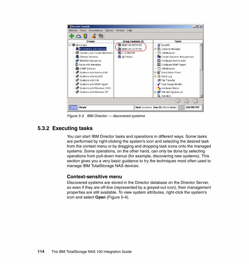
Figure 5-3 IBM Director — discovered systems
5.3.2 Executing tasksYou can start IBM Director tasks and operations in different ways. Some tasks are performed by right-clicking the system’s icon and selecting the desired task from the context menu or by dragging and dropping task icons onto the managed systems. Some operations, on the other hand, can only be done by selecting operations from pull-down menus (for example, discovering new systems). This section gives you a very basic guidance to try the techniques most often used to manage IBM TotalStorage NAS devices.
Context-sensitive menuDiscovered systems are stored in the Director database on the Director Server, so even if they are off-line (represented by a greyed-out icon), their management properties are still available. To view system attributes, right-click the system’s icon and select Open (Figure 5-4).
114 The IBM TotalStorage NAS 100 Integration Guide
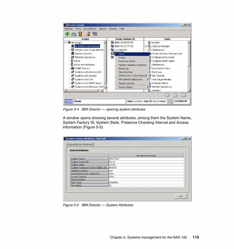
Figure 5-4 IBM Director — opening system attributes
A window opens showing several attributes, among them the System Name, System Factory ID, System State, Presence Checking Interval and Access information (Figure 5-5).
Figure 5-5 IBM Director — System Attributes
Chapter 5. Systems management for the NAS 100 115

Drag-and-drop operationsSeveral windows displayed in IBM Director consist of two or more panes. In most instances you can drag-and-drop task and target icons between these panes.
However, you cannot perform drag-and-drop operations between two separate IBM Director windows.
To execute a task on a managed system in the Console, drag the managed system icon from the Group Contents pane and drop it onto the task icon in the Tasks pane, as shown in Figure 5-6.
Figure 5-6 Dropping the system onto management task
A new window open for the started task — in this case the AssetID task (Figure 5-7). It displays Serial numbers, User, Lease, and Warranty information.
Figure 5-7 IBM Director — AssetID
Tip: You can also drag the task icon from the Tasks pane and drop it onto the desired managed system or group of systems icon in the left two panes.
116 The IBM TotalStorage NAS 100 Integration Guide

5.3.3 Grouping systemsGroups consist of logical sets of managed systems. An example of a group might be one that contains only NAS devices. When you first log on to the Console, a number of default groups are created. Included in this default list is the All Systems and Devices group, which contains all discovered devices. After the group is created and populated with desired systems, sharing same attributes, it is easier to run systems management tasks on the whole group.
5.3.4 Event and action managementEvent management in IBM Director is done using the Event Action Plan tool. It identifies and categorizes system events and initiates actions in response to those events. For example, it enables an administrator to determine when a file server’s hard disk drive is approaching its full capacity, so that he or she can provide a fix before users are affected. The administrator would use the Resource Monitor task to set a storage threshold on the file server; that configuration would generate an event when the remaining free space on the main data drive drops below, say, 500 MB. Using Event Management, the administrator can then configure an Event Action Plan that triggers a notification (console pop-up or page alert for example) when the threshold is exceeded.
Event Action Plans consist of two components:
� Event Filters: A set of specific criteria that determine if an incoming event will trigger an action
� Actions: The tasks that are executed as a result of the event
Event Action Plans can be associated with a system or a group of systems.
Using system threshold to generate an event (alert)When an IBM Director Server is installed, it already has some thresholds associated with subsystems like CPU, memory, disk, power supply. If there is a pending failure or critical usage of those resources, the administrator will receive notification about it without the need to configure it beforehand. However, in many environments, there will be a need for customized monitoring of resources, and for that reason, the administration personnel may have to modify existing or create new thresholds.
Probably the most important resource on the NAS appliance is disk space used for file storage. Here we describe the procedure to set up a disk threshold:
1. Login to Director Console and drag the Resource Monitors task from the Tasks pane (on the right) onto the selected system, as shown in Figure 5-8.
Chapter 5. Systems management for the NAS 100 117

Figure 5-8 IBM Director — starting Resource Monitor
2. The Resource Monitor window for the selected system opens. By clicking the + sign in front of Director Agent and Disk Monitors, select Drive D: Space Remaining. Right-click it and select Add to selected Resource Table (Figure 5-9).
Figure 5-9 IBM Director — add disk resource monitor
118 The IBM TotalStorage NAS 100 Integration Guide

3. The Disk Resource Monitor will be added to the Selected Resources pane and the Director will start collecting data. In a few seconds, current resource data — the remaining disk space, in our case — will be shown under the device name (Figure 5-10).
Figure 5-10 IBM Director — collecting disk data
4. Right-click the data value field and select Individual Threshold, as shown in Figure 5-11.
Figure 5-11 IBM Director — creating an individual threshold
5. In the Threshold Settings window, enter the values for the remaining disk space, which will trigger a Warning and an Error condition. Click OK to close the window (Figure 5-12).
Chapter 5. Systems management for the NAS 100 119

Figure 5-12 IBm Director — Threshold Settings
6. Now save the Resource Monitor by selecting File —> Save As, as shown in Figure 5-13.
Figure 5-13 IBM Director — Saving Resource Monitor
120 The IBM TotalStorage NAS 100 Integration Guide

7. Provide a meaningful name for the Resource Monitor you just created and click OK (Figure 5-14). Close the Resource Monitor window.
Figure 5-14 Resource Monitor Name
8. The last step needed is activating the Resource Monitor we just created. In the main Console window, drag the monitor from the Tasks pane and drop it onto the selected system (Figure 5-15).
Figure 5-15 Activating Monitor
9. The Activated Monitor will be represented with a blue check mark in the icon, as shown in Figure 5-16.
Chapter 5. Systems management for the NAS 100 121

Figure 5-16 IBM Director — Monitor Activated
Viewing the Event LogIf you want to verify the Threshold Monitor we just created, drag the Event Log from the Tasks pane onto your system (Figure 5-17).
Figure 5-17 IBM Director — starting Event Log
The Event Log window opens, as shown in Figure 5-18.
122 The IBM TotalStorage NAS 100 Integration Guide

Figure 5-18 Disk Space OK in Event Log
Now copy some files to the disk to fill it up until it reaches the predefined threshold. A Warning or Error event is shown in the Event Log now (Figure 5-19).
Figure 5-19 Disk Space Critical Error
Information: Selected entries can be deleted form the Event Log by clicking the Delete selected events icon from the Tool bar.
Chapter 5. Systems management for the NAS 100 123

Defining Event FiltersNow, as the Threshold Monitor is created and resource is being monitored, we need to define the Event Filter, which will receive all events and, based on the criteria defined, decide whether the event should trigger an action. Here is how you create a custom filter:
1. Click the Hammer icon in the Toolbar. This will open the Event Action Plan Builder window, right-click Threshold Event Filter, and select New, as shown in Figure 5-20.
Figure 5-20 Event Action Plan Builder
2. In the next window, remove the checkmark next to Any and expand the tree by clicking the + sign next to Director —> Director Agent —> Drive D: Space Remaining (Figure 5-21). Select the desired event type(s) and then save the Event Filter by clicking the diskette icon and providing a meaningful name for the Filter.
Figure 5-21 Selecting Event Type
124 The IBM TotalStorage NAS 100 Integration Guide

Defining Event ActionNow we need to define the action, which will be triggered upon reaching the preset threshold. IBM Director is offering a wide variety of action, which can be chosen depending on the situation and the severity of the alert. Some of the actions are listed here:
� Add a message to the console Ticker tape� Add to the Event Log� Log to textual Log file� Post to a news group (NNTP)� Send an alphanumeric or numeric page� Send an event message to the Console user� Send an Internet (SNMP) E-mail� Send an SNMP trap� Start a program on a system with the event or on the server� Start a task on a system with the event or on the server
With the exception of Add Event to Event Log, each type of event has to be customized by right-clicking it and selecting the Customize option.
In our example we will add the “Remaining disk space” message to the Ticker tape area of the main console. Here are the steps to achieve this:
1. In the Actions pane of the Event Action Plan Builder window, right-click Add a Message to the Console Ticker Tape and select Customize (Figure 5-22).
Figure 5-22 Customize Action
2. In the Message field enter the desired text, combined with variables for system (&SYSTEM), event text (&TEXT), time (&TIME) and date (&DATE) of the event, as shown in Figure 5-23.
Chapter 5. Systems management for the NAS 100 125

Figure 5-23 Define the Message
3. Click the Diskette icon and save the Action by entering a descriptive name and clicking OK (Figure 5-24).
Figure 5-24 Save Event Action
Creating an Event Action PlanNow that we have created the Event Filter and Event Action, we only need to combine them into an Event Action Plan. Here are the steps needed to do it:
Tip: If you want the message to be displayed on all management consoles, you can enter asterisk (*) character instead of specific usernames.
126 The IBM TotalStorage NAS 100 Integration Guide

1. Right-click the Event Action Plan icon in the “Event Action Plan Builder” window and select New, as shown in Figure 5-25.
Figure 5-25 Create Event Action Plan
2. Name the new Action Plan and confirm the save operation by clicking the OK button (Figure 5-26).
Figure 5-26 Save Event Action Plan
3. Add the customized Filter to the new Action Plan by dragging it from the middle pane to the left pane (Figure 5-27).
Figure 5-27 Add Filter to Action Plan
Chapter 5. Systems management for the NAS 100 127

4. Next, drag-and-drop the customized Action to the new Action Plan, as shown in Figure 5-28.
Figure 5-28 Add Action to Action Plan
5. The Action Plan is set up, as shown in Figure 5-29, so close the Builder window and return to the main Console window.
Figure 5-29 Event Action Plan created
128 The IBM TotalStorage NAS 100 Integration Guide

6. The last step is to activate the new Action Plan. Drag it from the Tasks pane onto the selected system in the Group Contents pane, as shown in Figure 5-30.
Figure 5-30 Activate the Event Action Plan
7. When the remaining disk space falls below the defined threshold, the event is processed and you will notice the message in the bottom part of the main Console — the Ticker Tape area, scrolling from right to left, as shown in Figure 5-31.
Tip: Even though the whole procedure might appear lengthy, the real value of Event Action Plans lies in their “reusability”. Once different Thresholds, Event Filters and Actions are created, they can be simply combined into several Action Plans and easily applied to different systems or groups of systems.
Chapter 5. Systems management for the NAS 100 129
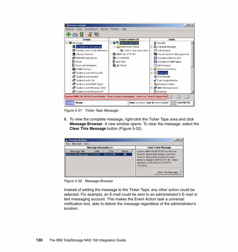
Figure 5-31 Ticker Tape Message
8. To view the complete message, right-click the Ticker Tape area and click Message Browser. A new window opens. To clear the message, select the Clear This Message button (Figure 5-32).
Figure 5-32 Message Browser
Instead of adding the message to the Ticker Tape, any other action could be selected. For example, an E-mail could be sent to an administrator’s E-mail or text messaging account. This makes the Event Action task a universal notification tool, able to deliver the message regardless of the administrator’s location.
130 The IBM TotalStorage NAS 100 Integration Guide

Importing Event Action PlansIf you have several IBM Director servers in your enterprise environment, you don’t have to create Event Action Plans on each of them separately. Instead, you create them on one of the servers and then redistribute to the rest of them. Both tasks can be accomplished by opening the Event Action Plan builder.
1. From the Menu bar, select File —> Export —> Archive, as shown in Figure 5-33.
Figure 5-33 Exporting Event Action Plan
2. Provide the filename and location for the archive and confirm the Save operation:
Figure 5-34 Saving Event Action Plan
3. To import the predefined Event Action Plan, first copy the Archive file to a local folder on your IBM Director server. In the Event Action Plan Builder, click File —> Import —> Archive, move to the folder where you copied the archive file, select the filename and confirm the operation by clicking OK (Figure 5-35).
Chapter 5. Systems management for the NAS 100 131

Figure 5-35 Importing Archive File
4. You will see the contents of the new Action Plan. Click Import to continue:
Figure 5-36 New Action Plan Contents
5. The new Action Plan is presented in the Event Action Plan Builder window, as shown in Figure 5-37.
132 The IBM TotalStorage NAS 100 Integration Guide

Figure 5-37 Imported Action Plan
6. The last step is to activate it by dragging it from the Tasks pane onto the selected system(s), as shown in Figure 5-38.
Figure 5-38 Activate the new Action Plan
5.3.5 Rack ManagerThe Rack Manager is a graphical representation of systems and devices, physically placed inside the rack. It can be used for status monitoring and management of racks and their components. See Figure 5-39.
Chapter 5. Systems management for the NAS 100 133

Figure 5-39 Rack Manager
For example, it is possible to visualize all components of a rack and then start management tasks from the same window by right-clicking the component and selecting the needed task. See Figure 5-40.
Figure 5-40 Starting Event Log from Rack Manager
134 The IBM TotalStorage NAS 100 Integration Guide

5.3.6 System AvailabilityThe System Availability tool can be used to track the availability of your IBM TotalStorage NAS appliance or a group of systems. Gathered information can be viewed as reports or graphical representations.
System Availability is able to distinguish between planned and unplanned outages. It will classify outages based on duration to help you track down reasons for system problems.
To start it, simply drag the System Availability task from the right pane onto the selected system or group of systems, as shown in Figure 5-41.
Figure 5-41 Starting System Availability tool
Note: This tool uses information from the operating system log (Event Log in Windows). If you clear the logs, all System Availability data will be lost as well.
Chapter 5. Systems management for the NAS 100 135

To select the time period, for which the availability data will be displayed, select File —> Set Time. In the window that opens, you can choose between All time, a week, a month, 3 months, a year, or a customized period. Click Update to confirm the chosen period (Figure 5-42).
Figure 5-42 Setting the time period
Different types of availability information can be chosen from the View menu. The following views are available:
� Distribution of system outages (Figure 5-43):
This displays a pie chart of how long the systems were down before being restarted, represented as a percentage.
Figure 5-43 Distribution of System Outages
136 The IBM TotalStorage NAS 100 Integration Guide

� Distribution of system uptime (Figure 5-44):
Displays a pie chart of how long the systems were up before being restarted.
Figure 5-44 Distribution of System Uptime
� System outages by day of week (Figure 5-45):
Displays the day of the week that outages occurred for the system or group as a percentage of downtime.
Tip: If you position the cursor on a particular segment of the chart, detailed statistics of that segment (duration and number of outages, uptimes, daily statistics) will be shown in a pop-up box.
Chapter 5. Systems management for the NAS 100 137

Figure 5-45 System Outages by Day of Week
� System outages by hour of day (Figure 5-46):
Displays the time of the day that outages occurred for the system or group as a percentage of downtime.
Figure 5-46 System Outages by Hour of Day
138 The IBM TotalStorage NAS 100 Integration Guide

� Report of system availability (Figure 5-47):
Displays a detailed report of the system’s availability including the list of all uptimes and downtimes. Additional statistical parameters are displayed, including total restarts, number of systems restarted (if the task was started against a group) and mean time between unplanned outages.
Figure 5-47 Report of System Availability
5.3.7 Capacity ManagerCapacity Manager is an efficient system management tool integrated into IBM Director to help you measure the potential bottlenecks of various subsystems. You can use this tool to forecast performance degradation of IBM xSeries servers and TotalStorage NAS appliances. You can plan for an appropriate action to overcome the bottleneck well in advance, so as to prevent overall performance degradation.
The key concept to understand about Capacity Manager is that the data is always being gathered. Unlike Windows 2000’s System Monitor, you do not have to start the logging of data. With Capacity Manager, you simply specify what data you want retrieved from the systems in your network and it is gathered and displayed graphically for you. Up to one month’s worth of data is automatically saved by every system.
Chapter 5. Systems management for the NAS 100 139

Collected data can also be exported into a spreadsheet for further analysis. These reports show at a glance potential bottlenecks within the selected systems. Analysis and ability to predict bottlenecks is critical when planning for future upgrades. Capacity Manager gives you the ability to plan the allocation of hardware upgrades for the systems that really need them before a capacity bottleneck occurs.
Capacity Manager is part of the IBM Director Server Extensions, so it comes preloaded on the IBM TotalStorage NAS devices.
When you start the IBM Director Console, the Capacity Manager icons will appear in the task pane of IBM Director as shown in Figure 5-48.
Figure 5-48 Capacity Manager tasks
You can perform four functions from this menu:
1. Double-click any of the four Using Capacity Manager tasks (as shown in Figure 17-2) to learn about Capacity Manager:
– New features– Overview– Report Viewer tour– Steps to create a report
If you are new to IBM Director and/or Capacity Manager, we suggest you review each of these help topics.
140 The IBM TotalStorage NAS 100 Integration Guide

2. Change what data is recorded on specific clients using Monitor Activator (see “Monitor Activator” on page 420).
3. Generate a report either directly to the viewer or to a report file using Report Generator (see “Report Generator” on page 421).
4. View a report that has already been generated using Report Viewer (see “Report Viewer” on page 432).
Monitor ActivatorThe Monitor Activator function is where you specify what data is to be gathered on specific clients or groups of clients. Simply drag the Monitor Activator icon onto a group or a single client to activate it. The screen shown in Figure 5-49 appears.
Figure 5-49 Monitor Activator window
Some of the counters (CPU Utilization, process count, Disk workload and usage, memory usage, Network Interface) are enabled (active) by default. They are represented with corresponding icons for an active monitor (see the Legend pane in Figure 5-49).
Other monitors have to be enabled by clicking the corresponding monitor in the left pane, and selecting the On button. When you are done enabling the monitors, you need to apply the changes by clicking the Apply button.
Chapter 5. Systems management for the NAS 100 141

Report GeneratorWith this task you gather data from specific systems and either display it on the screen (using the Report Viewer) or save it to a report file. Here are the predefined report definitions (as shown in Figure 5-48 on page 140):
� Daily Report (to viewer)� Hourly Bottleneck Events (to file)� Hourly Report (to viewer)� Monthly Report (to file)� Weekly Report (to file)
You can also create a new report by double-clicking New Report Definition in the IBM Director management console.
You can do the following with predefined reports:
� Execute it, just as you can with report definitions you’ve created, by dragging and dropping one onto a client or group of clients.
� Edit it by double-clicking the entry in the management console.
� Delete it by right-clicking the entry and clicking Delete.
� Changing the output definition from viewer to file or from file to viewer by right-clicking and clicking To viewer or file.
To generate a report, simply drag the report definition onto a client or a group of clients as shown in Figure 5-50.
Figure 5-50 Generating a Report
142 The IBM TotalStorage NAS 100 Integration Guide

If you choose to output the report to the Report Viewer, you will see a progress window showing the status of data being gathered from each system. The Report Viewer then loads and displays the results.
If your report definition specified to output to a file, then you will see the following dialog box asking if you want to execute it immediately or to schedule the task to be executed at a later time.
Figure 5-51 Output to file dialog box
If you select Execute Now, the progress window will show up (Figure 5-52), informing you about the status of the reporting process.
Figure 5-52 Report to file progress window
Regardless of which you pick, the report is saved to a file on the IBM Director Server (not the console). The name of the report is the name of the report definition, plus the time and date the report was created.
Report ViewerThe Report Viewer is used to examine reports you have requested to be gathered immediately or to examine reports you have saved to a file. The viewer starts automatically if the report definition you used specifies the output to go to the viewer.
Chapter 5. Systems management for the NAS 100 143

To view a report that was saved to a file, double-click the Report Viewer icon from the task panel in the management console. You will then be prompted to select a report file (.CMR or .TXT) from the IBM Director server’s C:\PROGRAM FILES\DIRECTOR\REPORTS directory.
A typical Report Viewer window is shown in Figure 5-53. As you can see, it is made up of three window panes:
Figure 5-53 Report Viewer
� The system pane is on top; it shows the systems, chosen for the report.
� The monitor pane is on the lower left-hand side, which lists the monitors you have chosen in the Report Generator. Here you can select only one monitor at a time to be displayed in the Graph pane.
� The graph pane is on the lower right-hand side, where the chosen monitor is displayed in the graphical format.
To display data on the graph, select a monitor from the Monitor pane, then one or more systems from the System pane (select more than one system with the Shift or Ctrl key). Figure 5-53 shows the CPU Utilization monitor selected for the NAS 100 system. To make the graph larger, select the edge of the pane with your mouse and drag the panel up or left.
If you want to analyze a particular part of the graph, you can zoom into it by clicking the Zoom button and then clicking into a particular part of the graph, as shown in Figure 5-54.
144 The IBM TotalStorage NAS 100 Integration Guide

Figure 5-54 Zooming into Graph pane
ForecastThe forecast function is available by clicking the Forecast button while viewing the Capacity Manager report, as shown in Figure 5-55. The function allows you to see Capacity Manager's prediction of the future performance of your selected systems. The forecast is for whatever monitor you currently have selected. To see a forecast for another monitor, click its name in the monitor box.
For the forecast to be valid, Capacity Manager needs a minimum of 21 days of previously collected data where the system monitors have been running at least 50% of the time.
The forecast line is a dashed line with an arrow at the end. The forecast interval is a multiple of your data collection period. The default prediction period is set to the same length as the data collection period. For example, if you have a month of collected data, the forecast will be for a month into the future.
The confidence interval is represented by the dotted lines above and below the forecast line. The vertical bar at the beginning of the forecast data depicts the range. The gap between the actual collected data and the beginning of the predicted data serves as a separator between these two data sets.
Chapter 5. Systems management for the NAS 100 145

Figure 5-55 Forecast Graph
Capacity Manager will display one of two warnings if your forecast is not valid. Invalid forecasts should not be used to make decisions about your systems.
� “Data collection period too short for a valid forecast.” To generate a valid forecast, you need at least 21 days of data.
� “System 'X' does not have enough data for forecasting”, or “Multiple systems do not have enough data for forecasting.”
One of these two messages will appear when you have a sufficiently long period for data collection, but one or more monitors were not on for at least 50% of the time during the data collection period.
Performance Analysis featurePerformance Analysis is a new artificial intelligence feature that probes for bottlenecks in system’s hardware performance, diagnoses the problem, and suggests ways to improve performance. The performance analysis algorithm is based on the experiences of experts. The algorithm can find many but not all system problems. A minimum of a month’s worth of data is needed to make accurate predictions.
The algorithm monitors four system functions:
� Memory� Disk subsystem� CPU� Network
Note: Performance analysis is only available on Windows NT and Windows 2000 systems.
146 The IBM TotalStorage NAS 100 Integration Guide

The report produced by the performance analysis function consists of two main sections:
� Recommendations: a summary of the actions that are recommended, is shown in the top part of the Report window.
� Details: all analysis results, are graphically represented in the bottom part of the Report window
To see the results of the performance analysis on your data, click the Performance Analysis button on the tool bar or use the ALT+N keyboard combination. A window similar to Figure 5-56 appears.
Figure 5-56 Performance Analysis Report
The report presents the bottleneck information first as a summary of the recommendations, then in a more detailed format, as shown in Figure 5-56. It also has links to the supporting graphic data. Keep in mind that bottleneck detection and analysis are complicated. If a monitor seems to be missing in one bottleneck, it may be because it is contributing to another one.
Chapter 5. Systems management for the NAS 100 147
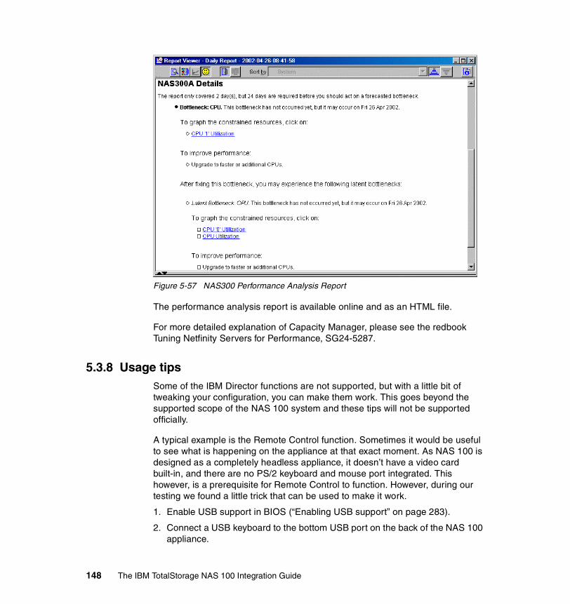
Figure 5-57 NAS300 Performance Analysis Report
The performance analysis report is available online and as an HTML file.
For more detailed explanation of Capacity Manager, please see the redbook Tuning Netfinity Servers for Performance, SG24-5287.
5.3.8 Usage tipsSome of the IBM Director functions are not supported, but with a little bit of tweaking your configuration, you can make them work. This goes beyond the supported scope of the NAS 100 system and these tips will not be supported officially.
A typical example is the Remote Control function. Sometimes it would be useful to see what is happening on the appliance at that exact moment. As NAS 100 is designed as a completely headless appliance, it doesn’t have a video card built-in, and there are no PS/2 keyboard and mouse port integrated. This however, is a prerequisite for Remote Control to function. However, during our testing we found a little trick that can be used to make it work.
1. Enable USB support in BIOS (“Enabling USB support” on page 283).
2. Connect a USB keyboard to the bottom USB port on the back of the NAS 100 appliance.
148 The IBM TotalStorage NAS 100 Integration Guide
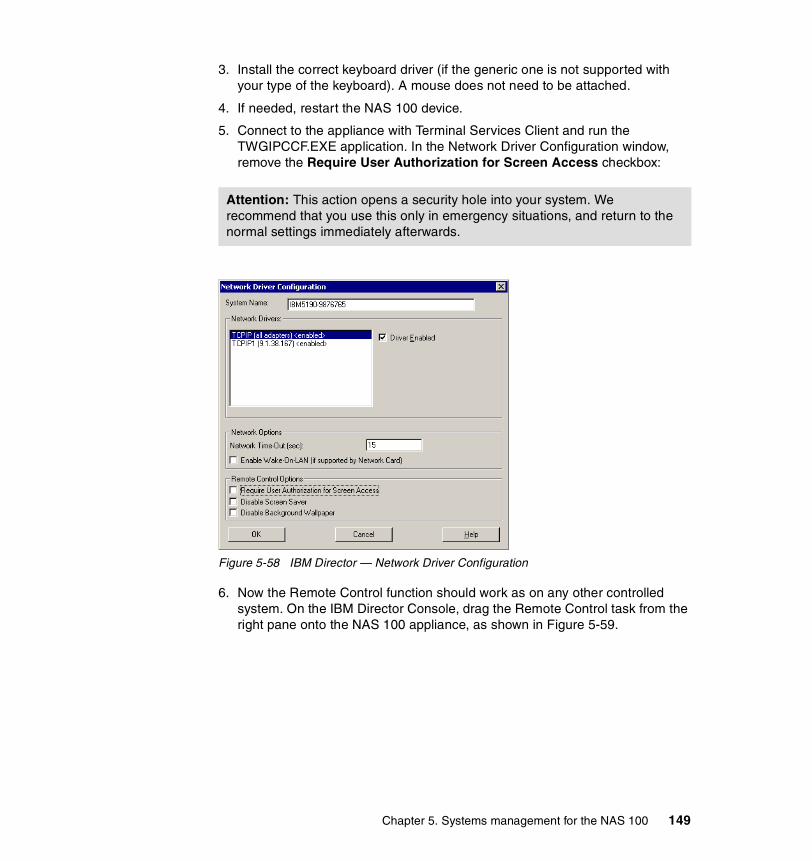
3. Install the correct keyboard driver (if the generic one is not supported with your type of the keyboard). A mouse does not need to be attached.
4. If needed, restart the NAS 100 device.
5. Connect to the appliance with Terminal Services Client and run the TWGIPCCF.EXE application. In the Network Driver Configuration window, remove the Require User Authorization for Screen Access checkbox:
Figure 5-58 IBM Director — Network Driver Configuration
6. Now the Remote Control function should work as on any other controlled system. On the IBM Director Console, drag the Remote Control task from the right pane onto the NAS 100 appliance, as shown in Figure 5-59.
Attention: This action opens a security hole into your system. We recommend that you use this only in emergency situations, and return to the normal settings immediately afterwards.
Chapter 5. Systems management for the NAS 100 149

Figure 5-59 Starting Remote Control
A new window opens with the NAS 100 desktop presented (Figure 5-60).
150 The IBM TotalStorage NAS 100 Integration Guide

Figure 5-60 Remote Control of the NAS 100 appliance
5.4 How to install IBM NAS Extensions to IBM DirectorThe IBM NAS Extensions to IBM Director provide capabilities to IBM Director that are specific to the IBM NAS Appliances. This enables detection and grouping of NAS appliances from Director.
In this section we show you how to install these extensions to IBM Director. You have to install the extensions on the machine with the management console.
The needed files are available on the Supplemental CD1 that is shipped with the NAS 100 appliance. The subdirectory name is /IBM NAS Extensions For IBMDirector.
1. Insert the CD-ROM into the machine’s CD-ROM drive. There is no need to stop the IBM Director services, because the installation program will do this by itself.
Chapter 5. Systems management for the NAS 100 151
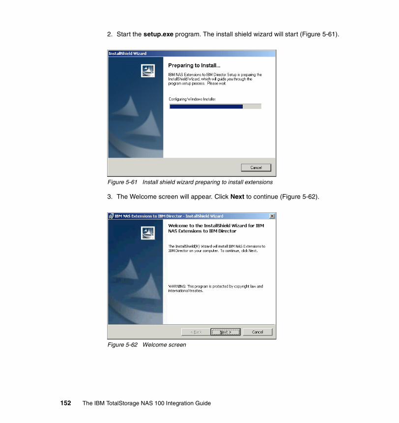
2. Start the setup.exe program. The install shield wizard will start (Figure 5-61).
Figure 5-61 Install shield wizard preparing to install extensions
3. The Welcome screen will appear. Click Next to continue (Figure 5-62).
Figure 5-62 Welcome screen
152 The IBM TotalStorage NAS 100 Integration Guide

4. Choose a destination folder or just click Next to continue (Figure 5-63).
Figure 5-63 Chose destination folder
5. The installation wizard is now ready for the installation process and asks for any changes. Click Install to start the installation (Figure 5-64).
Figure 5-64 Ready to install the extensions
Chapter 5. Systems management for the NAS 100 153

6. The installation wizard will install the extensions now. First it is generating scripts (Figure 5-65).
Figure 5-65 Generating scripts
7. A command line interface will open and the wizard starts its scripts (Figure 5-66, Figure 5-67).
Figure 5-66 Wizard is executing its scripts
Figure 5-67 Importing software dictionary entries
154 The IBM TotalStorage NAS 100 Integration Guide

8. The wizard will restart the IBMDirector services now (Figure 5-68, Figure 5-69).
Figure 5-68 Wizard is stopping the services
Figure 5-69 Wizard is starting the services
Chapter 5. Systems management for the NAS 100 155

9. Now it will remove the backup files (Figure 5-70).
Figure 5-70 Removing backup files
10.The installation is complete now (Figure 5-71).
Figure 5-71 Installation completed
156 The IBM TotalStorage NAS 100 Integration Guide

Now start the IBM Director to see the new features (Figure 5-72).You can see a new Group in the Groups window called IBM NAS Appliances. Whenever IBM Director recognizes a NAS appliance in the network, it will put it into this group.
Figure 5-72 Director console with new tasks for NAS appliances
You can see anther new feature in the Tasks window. This has been implemented to support the Web UI from the NAS appliances. Open the directory IBM NAS Appliances in the Tasks window and drag the Launch Web UI to the NAS 100 icon. The NAS Web UI will open in a new screen (Figure 5-73).
Note: This feature is not supported by the current BIOS version of the NAS appliances but will be implemented soon. The IBM Director will show the NAS appliances in the All Systems and Devices group.
Chapter 5. Systems management for the NAS 100 157
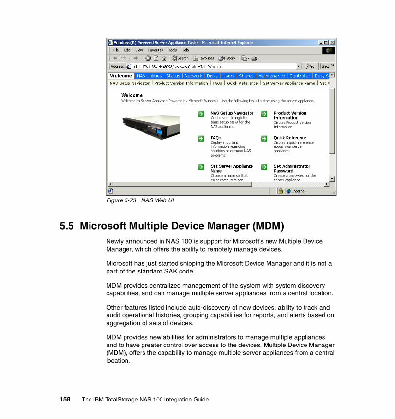
Figure 5-73 NAS Web UI
5.5 Microsoft Multiple Device Manager (MDM)Newly announced in NAS 100 is support for Microsoft’s new Multiple Device Manager, which offers the ability to remotely manage devices.
Microsoft has just started shipping the Microsoft Device Manager and it is not a part of the standard SAK code.
MDM provides centralized management of the system with system discovery capabilities, and can manage multiple server appliances from a central location.
Other features listed include auto-discovery of new devices, ability to track and audit operational histories, grouping capabilities for reports, and alerts based on aggregation of sets of devices.
MDM provides new abilities for administrators to manage multiple appliances and to have greater control over access to the devices. Multiple Device Manager (MDM), offers the capability to manage multiple server appliances from a central location.
158 The IBM TotalStorage NAS 100 Integration Guide

MDM features include:
� Auto-discovery of new devices added to the network� The ability to track and audit operational histories of the devices� Grouping capabilities for management purposes� Updated security� SAK Alert aggregation for sets of devices
5.5.1 NAS 100 and MDMThe NAS 100 is remotely managed from the Headquarters LAN by the Utility Administrator.
This customer segment often has no IT skill at all in the remote LAN locations and sometimes these locations are manless operations.
Using the 10/100/1000 Copper Gigabit Ethernet adapters, the customer can centrally manage many multiples of NAS 100s at remote locations.
Some of the tools that can be used include a Web browser, IBM Director, Microsoft Terminal Services, IBM Advanced Appliance Configuration Utility and Microsoft Multiple Device Manager. SNMP and standard MIBs are also supported.
� Software distribution (Figure 5-74)
– Use MS software install tools– Distribute upgrades simultaneously
Figure 5-74 Distribute software
Chapter 5. Systems management for the NAS 100 159
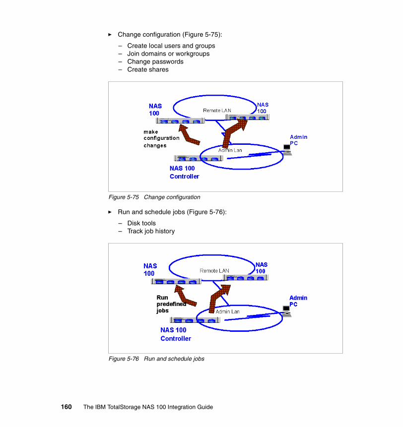
� Change configuration (Figure 5-75):
– Create local users and groups– Join domains or workgroups– Change passwords– Create shares
Figure 5-75 Change configuration
� Run and schedule jobs (Figure 5-76):
– Disk tools– Track job history
Figure 5-76 Run and schedule jobs
160 The IBM TotalStorage NAS 100 Integration Guide
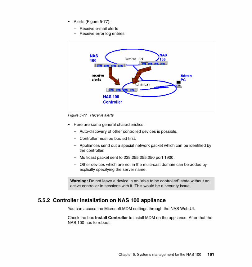
� Alerts (Figure 5-77):
– Receive e-mail alerts– Receive error log entries
Figure 5-77 Receive alerts
� Here are some general characteristics:
– Auto-discovery of other controlled devices is possible.
– Controller must be booted first.
– Appliances send out a special network packet which can be identified by the controller.
– Multicast packet sent to 239.255.255.250 port 1900.
– Other devices which are not in the multi-cast domain can be added by explicitly specifying the server name.
5.5.2 Controller installation on NAS 100 applianceYou can access the Microsoft MDM settings through the NAS Web UI.
Check the box Install Controller to install MDM on the appliance. After that the NAS 100 has to reboot.
Warning: Do not leave a device in an “able to be controlled” state without an active controller in sessions with it. This would be a security issue.
Chapter 5. Systems management for the NAS 100 161

You do also have the possibility to control NAS 100 from another appliance:
1. To give the box the ability to be managed from another box, choose Be Controlled from the Welcome screen of NAS Web UI. The Be Controlled tab will be shown on the screen (Figure 5-78).
Figure 5-78 Be controlled tab
2. Uncheck the Refuse Control option and reboot.
3. Now the appliance is able to be controlled from another NAS appliance.
5.5.3 MDM functionsThe MDM Welcome Screen gives you a survey of the MDM tools (Figure 5-79).
Figure 5-79 MDM Welcome Screen
Run JobsIn the Run Jobs tab, you can configure new jobs for remote appliances or sets (Figure 5-80).
162 The IBM TotalStorage NAS 100 Integration Guide
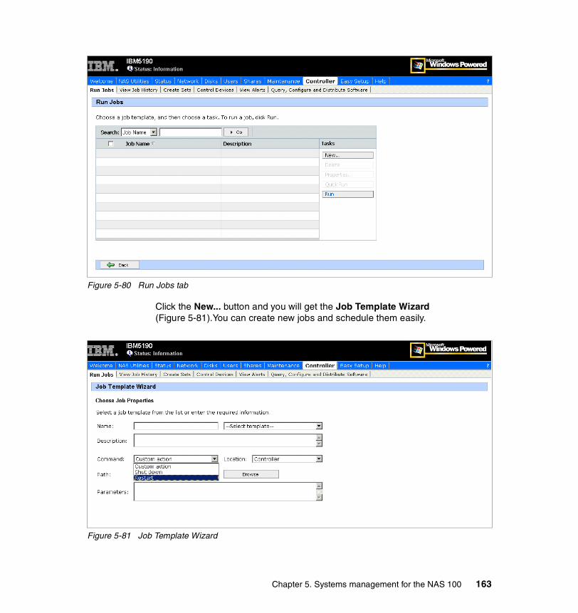
Figure 5-80 Run Jobs tab
Click the New... button and you will get the Job Template Wizard (Figure 5-81).You can create new jobs and schedule them easily.
Figure 5-81 Job Template Wizard
Chapter 5. Systems management for the NAS 100 163
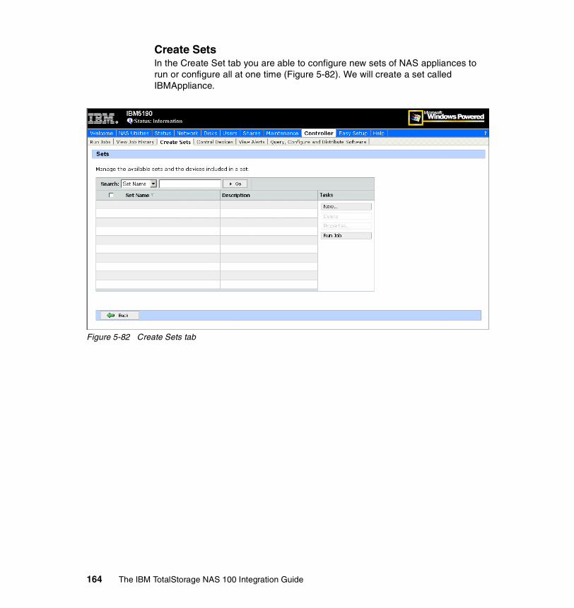
Create SetsIn the Create Set tab you are able to configure new sets of NAS appliances to run or configure all at one time (Figure 5-82). We will create a set called IBMAppliance.
Figure 5-82 Create Sets tab
164 The IBM TotalStorage NAS 100 Integration Guide

1. Click the New... button and the Create Set screen will open (Figure 5-83).
Figure 5-83 Create Set screen
Chapter 5. Systems management for the NAS 100 165

2. Insert a Name and Description for the set and add NAS appliances to your set by clicking the appliance and clicking the Add button.
3. Create the set with the OK button (Figure 5-84).
Figure 5-84 Set screen with the created IBMAppliance set
166 The IBM TotalStorage NAS 100 Integration Guide
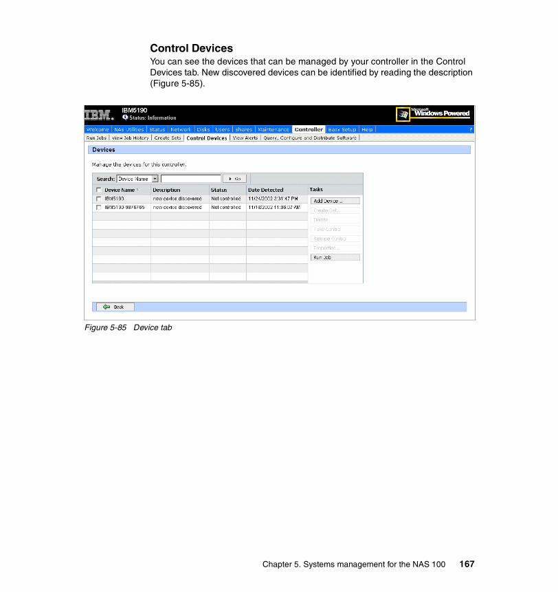
Control DevicesYou can see the devices that can be managed by your controller in the Control Devices tab. New discovered devices can be identified by reading the description (Figure 5-85).
Figure 5-85 Device tab
Chapter 5. Systems management for the NAS 100 167

Query, configure and distribute softwareYou have the possibility to query for appliances, set configuration, and distribute software on sets of devices (Figure 5-86).
Figure 5-86 Query, Configure and Distribute Software tab
168 The IBM TotalStorage NAS 100 Integration Guide
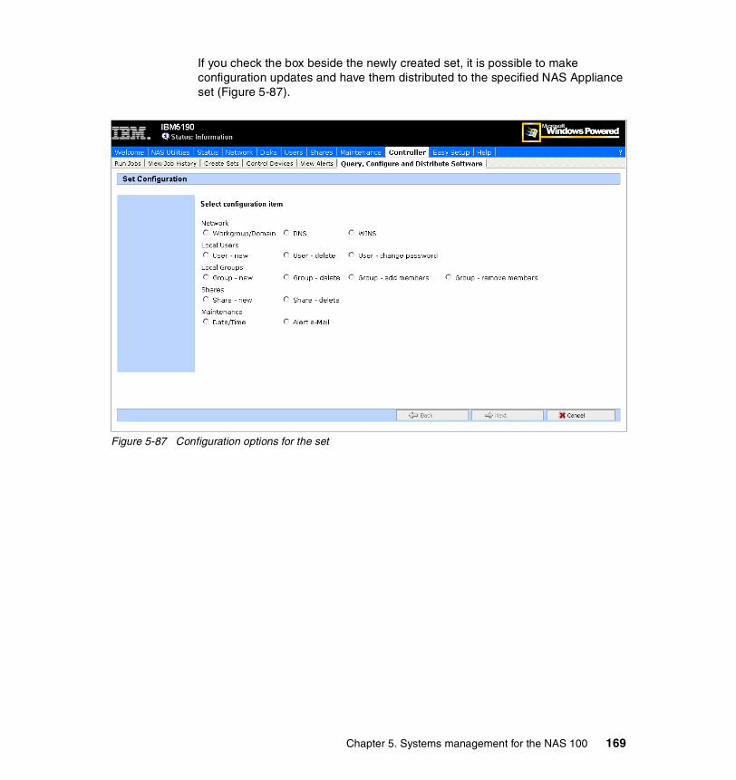
If you check the box beside the newly created set, it is possible to make configuration updates and have them distributed to the specified NAS Appliance set (Figure 5-87).
Figure 5-87 Configuration options for the set
Chapter 5. Systems management for the NAS 100 169

But if you choose Distribute Software... you can easily distribute Software without an additional tool (Figure 5-88).
Figure 5-88 Software Distribution Wizard
For more Information about the new Microsoft Multiple Device Manager (MDM), refer to:
http://www.microsoft.com/windows/Embedded/sak/evaluation/whatsnew/default.asp#mdm
170 The IBM TotalStorage NAS 100 Integration Guide

Chapter 6. Cross platform storage
We now have plenty of storage space that is owned by our NAS 100 system, and we want to give the other machines in our network access to it. In this chapter we provide all of the information necessary to use NAS appliances from Windows and UNIX clients.
Your operating environment will influence the type of file sharing that will be configured on the NAS appliance. If your network consists entirely of Windows clients, you should consult the material in 6.1, “File sharing for Windows clients” on page 172 and 6.2, “Accessing the shares from our Windows clients” on page 178.
If your operating environment consists entirely of UNIX clients, the material in 6.3, “File sharing for UNIX clients” on page 180 and 6.4, “How to configure Services For UNIX (SFU)” on page 184 will be helpful. You should also review 6.4.5, “Accessing the shares from our UNIX clients” on page 220.
If your operating environment consists of a mix of UNIX and Windows clients, in addition to 6.4, “How to configure Services For UNIX (SFU)” on page 184, you should carefully read the material in 6.4.4, “Mapping the Gateway for NFS share from a Windows client” on page 218, which describes how to access Network File System (NFS) shares from Windows clients.
Finally, in “Accessing the shares with the Samba client” on page 222, we show how to use the Samba client to connect to the NAS appliance in Linux and AIX hosts.
6
© Copyright IBM Corp. 2003. All rights reserved. 171

6.1 File sharing for Windows clientsThis section describes how to create shares for Windows clients. To ensure access for Windows users, we recommend having the NAS appliance join a Windows NT Domain or Active directory. However, if you do this, you must also create a separate account in NAS appliances.
The process of creating a share in a Windows server is a easy one. These are the steps you should follow to share a folder:
1. Login on the NAS 100 with the appropriate rights to create a share. The administrator account can always be used for doing this.
2. Create a folder that you want to share.
3. Right-click the folder and click Sharing to get the Sharing dialog box.
4. When you are creating a share for a complete disk, the Sharing dialog box shows that there is an administrative share name in place. The administrative share name ends with a dollar sign ($), as shown in Figure 6-1.
Figure 6-1 Administrative share
172 The IBM TotalStorage NAS 100 Integration Guide

5. In order to set up a share that would work well for us later on, we selected the Do not share this folder option and clicked Apply (Figure 6-2).
Figure 6-2 Getting rid of the administrative share
Important: To ensure access for Windows users other than administrators, you should always define an explicit share. Although on Windows NT and 2000 there is already a hidden administrative share present by default, you should not use it as a share for users. Instead, you need to create designated user shares.
Chapter 6. Cross platform storage 173
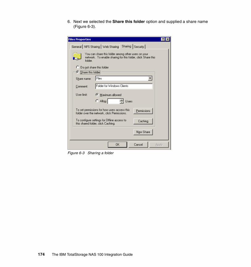
6. Next we selected the Share this folder option and supplied a share name (Figure 6-3).
Figure 6-3 Sharing a folder
174 The IBM TotalStorage NAS 100 Integration Guide

7. Before accepting this share, we clicked the Permissions button so security for the share could be adjusted to meet our needs (Figure 6-4).
Figure 6-4 Permissions for the Windows share
8. You can also modify the NTFS permissions. Click the Security tab (refer back to Figure 6-3 on page 174) and then click Add.
Important: Permissions on Windows shares are a combination from network share and local NTFS file system share permissions. Those permissions work cumulatively.
Chapter 6. Cross platform storage 175

9. Choose all users and groups that you want to grant access to this folder (Figure 6-5).
Figure 6-5 Select users
176 The IBM TotalStorage NAS 100 Integration Guide

10.Configure the correct permissions for those users and groups, and finish by clicking Apply (Figure 6-6).
Figure 6-6 Modifying permissions
Once the shares were ready, they appeared, as “handed out”, in the Windows Explorer.
To check your current Windows shares from a DOS prompt, you can use the net share command to display all your current shares.
Chapter 6. Cross platform storage 177

6.2 Accessing the shares from our Windows clientsFrom Windows, accessing the share was extremely straightforward. We just went into the Network Neighborhood (or My Network Places, as Windows 2000 prefers to call it), drilled down to the NAS 200, supplied a user name and password, right-clicked the shared directory, and chose Map Network Drive (Figure 6-7).
Figure 6-7 Map Network Drive
178 The IBM TotalStorage NAS 100 Integration Guide

We were presented with a window requesting a drive, a folder, and were asked whether or not we wanted to reconnect at login (Figure 6-8).
Figure 6-8 Windows mapping information
Once we supplied that information, we were able to see the shared disk, read from it, and write to it. You can check it using Windows explorer or executing the net use command from a DOS command prompt.
Another way of getting connected is by using the net use command. If you prefer the command line style, see Example 6-1.
Example 6-1 The net use command
C:\>net use /?The syntax of this command is:NET USE [devicename | *] [\\computername\sharename[\volume] [password | *]] [/USER:[domainname\]username] [/USER:[dotted domain name\]username] [/USER:[username@dotted domain name] [[/DELETE] | [/PERSISTENT:{YES | NO}]]NET USE {devicename | *} [password | *] /HOMENET USE [/PERSISTENT:{YES | NO}]
NET USE EXAMPLE: net use x: \\ibm5190-9876765\users password /user:administrator
Chapter 6. Cross platform storage 179

6.3 File sharing for UNIX clients
Enabling access for UNIX systems requires just one more step. From the same dialog, we click the NFS Sharing tab and set it up as well. This is shown in Figure 6-9.
There are five tabs at the top of this property folder. There are two tabs that require changes for UNIX sharing: NFS Sharing and Security.
1. Click NFS Sharing. Then click the radio button for Share this folder.
Figure 6-9 NFS sharing
Note: The Server for NFS is needed for NFS sharing and is already installed in the IBM TotalStorage NAS system.
Important: This procedure will result in a breakdown of group/user properties which are critical to system administrators in the UNIX world. You will experience some group/user ID problems while following these steps. We will show a different approach in the 6.4, “How to configure Services For UNIX (SFU)” on page 184 that maybe will better fit your needs.
180 The IBM TotalStorage NAS 100 Integration Guide

2. Once again, we assigned a name to the share. We chose to use the same name as we used for the Windows clients. This conveniently allows the shared directory to be mapped/mounted in the same way from both UNIX and Windows clients. In Services for UNIX 2.3 you have additional functions than you do in SFU 2.2. You can choose international encoding formats to get connections to nfs-clients with different character sets (Japanese, Korean, Taiwanese, etc.)(see Figure 6-10).
Figure 6-10 SFU 2.3 international character sets
Allowing anonymous access is not a security risk, so disabling it might provide a false sense of security. (The real security risk is to grant everyone access to resources that should be protected.) And disabling anonymous access has one severe consequence: It is so unexpected by NFS clients that they may not be able to connect as NFS V3 clients at all, and may instead downgrade the connection to use the NFS V2 protocol.
Figure 6-11 Anonymous access for Nfs sharing
Note on anonymous access: See Figure 6-11. It is strongly recommended that you do not disable anonymous access. If a client presents a UID that is not recognized, Server for NFS can still grant that client a very limited form of access as a special nobody user. This is known as anonymous access, and you can enable or disable it on a per-share basis. This anonymous user will have very limited access to resources on the NAS: it has only the permissions that are granted to the Everybody group in Windows, which corresponds to the other (or world) bits in a POSIX permissions mode.
Chapter 6. Cross platform storage 181
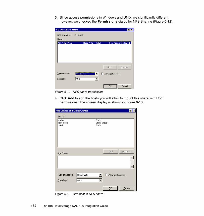
3. Since access permissions in Windows and UNIX are significantly different, however, we checked the Permissions dialog for NFS Sharing (Figure 6-12).
Figure 6-12 NFS share permission
4. Click Add to add the hosts you will allow to mount this share with Root permissions. The screen display is shown in Figure 6-13.
Figure 6-13 Add host to NFS share
182 The IBM TotalStorage NAS 100 Integration Guide

5. In this case we added one Linux host as a client running RedHat 8.0. The hostname is redhat.
6. Select that hostname and click Add. This action will display the redhat client in a smaller rectangle box below (Figure 6-14). Then click the down arrow, and select Read-Write. Check the Allow root access box to give this host root access to the share.
Most UNIX systems can mount a file system as root. The root use has the highest administrative rights on the UNIX system and is equivalent to the administrator account in Windows NT/2000 systems.
Figure 6-14 Set Root access for UNIX host
7. Then click OK, which brings you back to previous screen where you click OK again. Then, on the main NFS share window, click Apply.
Now you have completed the folder sharing configuration for UNIX.
To check your current NFS shares from a DOS prompt, you can use the nfsshare command to display all your current shares. This tool comes with Microsoft Services for UNIX.
Tip: To make your administration easier, we recommend using the same share name for Windows and UNIX shares.
Chapter 6. Cross platform storage 183

6.4 How to configure Services For UNIX (SFU)In a mixed environment, where UNIX and Windows clients will be accessing the storage of the NAS appliance, special care must be taken to ensure a consistent view of the data for all users who are granted access rights to it. If the storage is configured correctly, as described in this chapter, access to the data should be transparent to the user whether they are accessing it from a Windows or UNIX workstation.
The Network File System (NFS), described in 6.3, “File sharing for UNIX clients” on page 180, is the common file system for access in an environment where there are both UNIX and Windows clients. NFS is the “binding” agent that makes inter operability between these two, very diverse, operating systems possible. All accesses in this environment are through the “NFS Server” which is running in the NAS appliance.
Also, 6.3, “File sharing for UNIX clients” on page 180, describes the steps that are taken to export an NFS share from the NAS appliance. Then, 6.4.5, “Accessing the shares from our UNIX clients” on page 220 describes how to mount this NFS share from the UNIX client using the command line mount utility.
In this section we explain all of the steps that are required to access the NFS exported share from the Windows client. This includes, most importantly, the introduction of a new component — the Gateway for NFS share.
The NFS share is not native to the Windows operating system and, therefore, cannot be accessed directly from a Windows client on the network. Special NFS client software could be added to the Windows workstation allowing its user to access the share in much the same way as the UNIX client. However, there is a simpler way to accomplish this using another feature of the NAS appliance.
What is an NFS Gateway?An existing NFS share can be used to create a new Windows drive which can then be mapped directly from a Windows workstation on the network. This new drive, called a Gateway for NFS share, is accessible from the network like any other Windows share. The significant difference is that file access requests for this share are passed through to the Services for UNIX components, NFS Server and User Name Mapping. In this way a consistent view of the data is preserved for all users and access to the data is transparent to the user whether they are accessing it from a Windows or UNIX workstation.
184 The IBM TotalStorage NAS 100 Integration Guide

A sample access to the Gateway for NFS is shown in Figure 6-15.
Figure 6-15 Gateway for NFS access
We strongly recommend to use NAS Code Release 2.5 (SFU 2073.1) for heterogeneous file sharing.
6.4.1 Configuring a cross platform share in a Windows 2000 DomainThe purpose of this chapter is to give a brief introduction how to set up SFU “Services For UNIX” for heterogeneous file sharing between UNIX and Windows. The intention cover the basic installation in the most common customer environments with a Windows 2000 Domain.
Configuring the Windows 2000 Domain controllerBefore you can use SFU in your network environment, it is required to install the SFU “Server for NFS Authentication” on your Domain controller.
1. Insert the Supplemental CD 2/2 shipped with the NAS100 box and select the folder SFU_xxxx (Figure 6-16).
NAS master
NFS Server
Gateway for NFS
\\NAS\gway_master mount NAS:/nfs_master ..
WindowsWorkstation
UNIXWorkstation
NFS Share name: nfs_master
Gatew ay for NFS Share name: gw ay_master
Chapter 6. Cross platform storage 185

Figure 6-16 SFU 2073.1 on the Supplementary cd 2/2
2. Unzip the SFU22.exe by double (Figure 6-17).
Figure 6-17 Unzip screen for SFU22.exe
186 The IBM TotalStorage NAS 100 Integration Guide

3. Choose a different temporary location or click Extract. Confirm to create the temporary directory with Yes (Figure 6-18).
Figure 6-18 Create temporary directory
4. The program will start to inflate the zipped files (Figure 6-19).
Figure 6-19 Inflating the installation files
Chapter 6. Cross platform storage 187
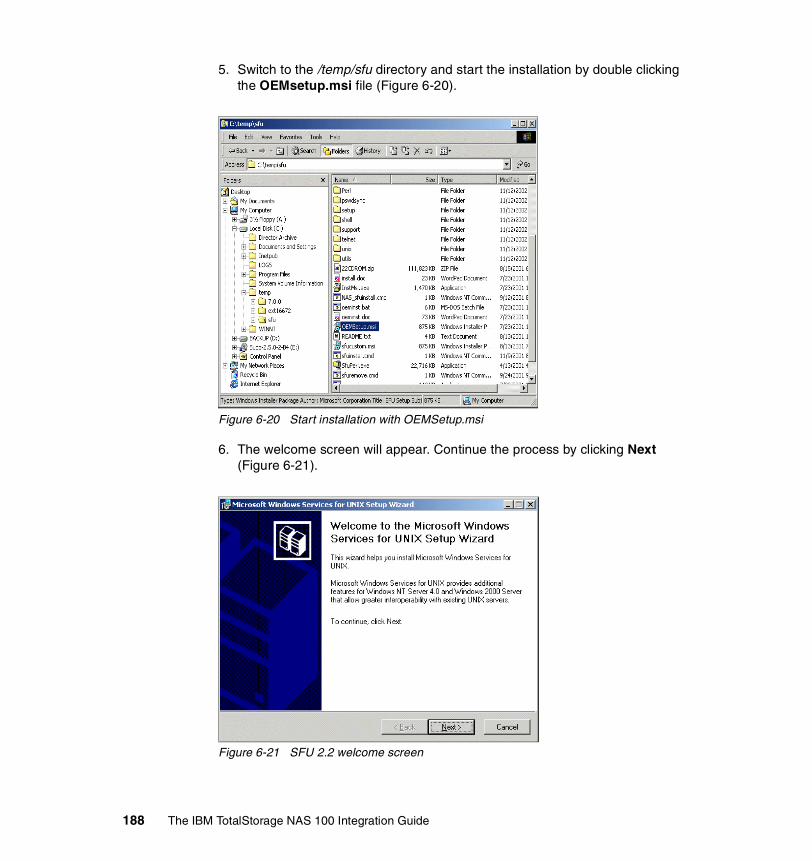
5. Switch to the /temp/sfu directory and start the installation by double clicking the OEMsetup.msi file (Figure 6-20).
Figure 6-20 Start installation with OEMSetup.msi
6. The welcome screen will appear. Continue the process by clicking Next (Figure 6-21).
Figure 6-21 SFU 2.2 welcome screen
188 The IBM TotalStorage NAS 100 Integration Guide

7. Accept End-user license agreement (Figure 6-22).
Figure 6-22 End-User license agreement
8. After inserting the customers information (name and company name) the Installation Options screen will appear (Figure 6-23). Select Customized installation and click Next.
Figure 6-23 Installation Options screen
Chapter 6. Cross platform storage 189

9. Unselect everything except “Server for NFS Authentication” (Figure 6-24).
Figure 6-24 Select “Server for NFS Authentication”
10.Choose a different location for the program files or click Next (Figure 6-25).
Figure 6-25 Location for SFU
190 The IBM TotalStorage NAS 100 Integration Guide

11.Now the installation program will install the Service on the Domain controller (Figure 6-26).
Figure 6-26 Installation of SFU
12.Click Finish after the installation process (Figure 6-27).
Figure 6-27 Completing Setup screen
13.Create additional Windows and Groups for heterogeneous file sharing in the Domain controllers Active Directory (only if needed).
Chapter 6. Cross platform storage 191

14.Execute Start->Programs->Administrative Tools->Active Director Users and Computers
15.Select the User, select the tab Member of and set the primary group to one that will be mapped in SFU (Figure 6-28).
Figure 6-28 Primary group from winuser set to wingroup for SFU
Configuring the AIX ClientWe assume your AIX Client is up and running.
Create Users and Groups for heterogeneous file sharing if needed.
Configuring the Windows ClientWe assume your Windows Client is up and running.
Connect the Windows Client to the Windows Domain Controller (logon to the Domain with a valid Domain User Account).
Note: The primary group must be set to a group that is mapped in SFU for every user that will be used for heterogeneous file sharing, otherwise “nobody” (->”ls -al” command) will be displayed.
192 The IBM TotalStorage NAS 100 Integration Guide

Configuring the NAS 100The next step is to set up Microsoft Services For UNIX (SFU) on the NAS 100. This is an additional software that runs on the Windows Powered OS on the NAS server. There are various steps of configuration that need to be done. Those steps are documented step-by-step in this section.
Before you configure the users and groups on Windows2000 server and Services for UNIX, you need to identify all users on the UNIX side which will be accessing this shared resource. The root user must be defined. So the root user can mount a shared NAS resource as a file system on UNIX server. The user and group information can be found in two systems files. They are /etc/passwd and /etc/group on most UNIX systems, unless a Network Information Services (NIS) service has been set up. We did not use a NIS setup, so we used the /etc/passwd and /etc/group files for the information.
We assume that you are an experienced Windows administrator, so we are covering the process of how to create users and groups on a Windows 2000 server. We will need this information for mapping as a part of the configuration.
Apply Fixes if neededThe NAS 100 box has SFU 2.2 installed with the HotFixes QFE 320174 and QFE 321096. Any NAS box that has installed the SFU QFE Q320175 installed may encounter a problem after 8/1/02 due to the inclusion of a beta expiration check into that QFE. This check will render the component unusable.
http://www-1.ibm.com/support/docview.wss?uid+ssg1S1001387
Get the Password and Group files from UNIXFtp /etc/passwd and /etc/group from the AIX Client to the NAS 100 (NAS 100 path: c:\winnt\system32\drivers\etc). Ftp the passwd and group files in binary mode from the AIX workstation to the NAS 100 (Figure 6-29 on page 194).
1. Open the command prompt.
2. change to the \winnt\system32\drivers\etc\ folder on your c: drive.
3. To transfer the files type ftp xxx.xxx.xxx.xxx and press Enter.
4. Login with a valid UserID and password.
5. Type bin for binary mode and press Enter.
6. Type get /etc/passwd to transfer the first file.
7. Type get /etc/group to transfer the second file.
8. Close the ftp session by entering bye and pressing Enter.
Chapter 6. Cross platform storage 193

Figure 6-29 Ftp /etc/passwd and /etc/group to the NAS 100
The /etc/group file contains information that is not needed by the PCNFS Server. The Server would not accept the group information from the file. For that reason it is important to modify the group file for further use.
9. Open the Windows Explorer and click move to the /winnt/system32/drivers/etc directory (Figure 6-30).
Figure 6-30 Directory for /etc/group and /etc/passwd
194 The IBM TotalStorage NAS 100 Integration Guide

10.Right-click the group file (Figure 6-31).
Figure 6-31 Open /group with...
11.Choose Notepad to open the file (Figure 6-32).
Figure 6-32 Choose Notepad
Chapter 6. Cross platform storage 195

12.Click the Edit tab and choose Replace... (or Ctrl-H) (Figure 6-33).
Figure 6-33 Edit Replace tab
13.Enter an exclamation Mark (!) in Find what and click the Replace All button (Figure 6-34).
Figure 6-34 Replace exclamation mark wit nothing
14.Notepad will erase all exclamation marks. Save and close the file after the procedure. The file can now be used with the PCNFS Server.
196 The IBM TotalStorage NAS 100 Integration Guide

Configuring SFU on the NAS 1001. Click the IBM NAS admin.msc icon on your desktop.
2. Then click the + next to the file system and select Services for UNIX. You will see the Services for UNIX screen, including all details and release levels. Here, we have Services for UNIX V2.2 in our environment (Figure 6-35).
Figure 6-35 Services for UNIX main screen.
3. Click Server for NFS.
4. Click User Mapping tab and you will see a display like the one in Figure 6-36.
Figure 6-36 Server for NFS user mapping
Specify the computer name of the server that is running the User Name Mapping Service. If User Name Mapping will be configured to run on this NAS appliance, specify localhost or the machine name.
Chapter 6. Cross platform storage 197

5. Select User Name Mapping from the left navigation bar (Figure 6-37).
Figure 6-37 User Name Mapping
6. Select Personal Computer Network File System (PCNFS) since we are not using a NIS Server in our environment.
7. Point the Password and Group file path to the “passwd” and “group” file ftp location on the NAS 100, as it is shown.
8. Select Maps in the right window.
Note: Make sure to apply every changes by clicking the “Apply” button in the right corner.
198 The IBM TotalStorage NAS 100 Integration Guide

9. Select Simple Maps in order to map users with the same user name in the Windows and UNIX environment. Make sure you have selected your Window Domain (Figure 6-38).
Figure 6-38 User Name Mapping / Maps
10.Click the Show User Maps tab.
11.Select the List Windows Users and List UNIX Users buttons.
12.Select the Windows user root from the Windows users list and the UNIX user root from the UNIX users list.
13.Click the Add button to add a mapping for these two users.
14.You can create mappings between other UNIX and Windows users at this time. This is shown in Figure 6-39.
Chapter 6. Cross platform storage 199

Figure 6-39 User name mapping on NAS 100
15.Click the Show Group Maps link.
16.Select the List Windows Groups and List UNIX Groups buttons.
17.Select the Windows group Domain Admins from the Windows groups list and the UNIX group system from the UNIX groups list.
18.Click the Add button to add a mapping for these two groups.
19.Map all needed groups from the Windows system to according groups from the UNIX system (Figure 6-40).
Important: Be aware of the Windows domain box, which says \\ITSOLAB2. That is where users and groups will be mapped to, and that is where authentication will be done. If you do not select the right domain there, then you will have file access problems on the UNIX client side.
200 The IBM TotalStorage NAS 100 Integration Guide

Figure 6-40 Group mapping on NAS 100
The Microsoft Services for UNIX are now configured within the Windows Domain.
Note: Make sure everything is applied before you close the SFU configuration. Step back to Configuration tab and click the Synchronize Now button to refresh user and group names.
Chapter 6. Cross platform storage 201

20.Open a DOS prompt and verify the User and Group mapping by the DOS command mapadmin list -all (Figure 6-41).
Figure 6-41 Verifying Maps by DOS command mapadmin
Congratulations! Now you have successfully completed your Services for UNIX setup. You should be able to mount shared folders into the file system to your UNIX clients.
For further steps, refer to “Configuring the shared storage” on page 211.
6.4.2 Configuring a cross platform share without a Domain ControllerLog on via Terminal Services Client or NAS 100 Web GUI interface->Maintenance->Terminal Services to a NAS 100 with administrative access. Open the IBM NAS Admin by clicking its icon on the desktop.
Creating new Windows User accounts:These are the steps for creating new Windows User accounts:
1. Click the + sign beside NAS Management.
2. Click the + sign beside Users and Groups.
3. Click the + sign beside Local Users and Groups (Local).
4. Click Users.
5. Create a new user called root.
202 The IBM TotalStorage NAS 100 Integration Guide

6. Add the new user root to the Administrators group.
7. Create a new group called support.
8. Create a new user called charlie.
9. Add the new user charlie to the support group.
Add any other new Windows users that you will want to map to corresponding UNIX users at this time.
Configuring the Services for UNIX componentsThese are the steps for configuring the Services for UNIX components:
1. Click the + sign beside NAS Management.
2. Click the + sign beside Maintenance.
3. Click Services.
Scroll down the list of services and verify that the following services are Started:
� Gateway for NFS� Server for NFS� Server for PCNFS� User Name Mapping
Configuring Server for NFSThese are the steps for configuring Server for NFS:
1. Click the + sign beside NAS Management.
2. Click the + sign beside File Systems.
3. Click the + sign beside Services for UNIX.
4. Click Server for NFS.
5. Click User Mapping tab and you will see a display like the one in Figure 6-42.
Figure 6-42 Server for NFS user mapping
Chapter 6. Cross platform storage 203

Specify the computer name of the server that is running the User Name Mapping Service. If User Name Mapping will be configured to run on this NAS appliance, specify localhost or the machine name.
6. Click the Client Groups tab (refer to Figure 6-43).
Root access to the NFS share is granted on a per-machine basis. It is very common that some machines will need root access to the NFS share. Here we will create a special client group (or netgroup) and add machine names to the group:
7. Create a client group called root_users by supplying a name in the Group name: field and selecting the New Button. The new group should appear in the Current groups list. Select the root_users group from the Current groups list and select the Advanced link.
8. Add the IP address, or hostname, and click Add Clients for each machine that you want to add to this group.
Figure 6-43 Server for NFS client groups
204 The IBM TotalStorage NAS 100 Integration Guide

9. You can create other client groups at this time if needed. This completes the configuration of Server for NFS. Click the Apply button in the upper right corner to save your changes.
Configuring the Gateway for NFSNext we describe how to configure the Gateway for NFS.
1. Click Gateway for NFS.
2. Select the Authentication tab and specify the computer name running the User Name Mapping Service. In this case we will specify the NAS appliance host name (localhost would also work here!). This is shown in Figure 6-44.
Figure 6-44 Gateway for NFS authentication
This completes the configuration of Gateway for NFS. Click the Apply button in the upper right corner to save your changes.
Configuring the Server for PCNFSNext we describe how to configure the Server for PCNFS.
3. Click Server for PCNFS, and the window shown in Figure 6-45 will appear when you click the Groups tab.
Chapter 6. Cross platform storage 205

Figure 6-45 Server for PCNFS new group
4. Create a new group called root with GID (group ID) of 0. Create another new group called support with GID of 2583. Add other UNIX groups at this time being careful to specify the GID exactly as it is specified in the /etc/group file in your UNIX clients or NIS database.
5. Create a new user root with a UID (user ID) of 0. The primary group for this new user is root. Create a new user charlie with GID of 505 and primary group support. Add other UNIX users at this time being careful to specify the UID exactly as it is specified in the /etc/passwd file in your UNIX clients or NIS database.
6. Click the Groups tab again.
206 The IBM TotalStorage NAS 100 Integration Guide

7. Add the new user root as a member of group root. Add the new user charlie as a member of group support. This is shown in Figure 6-46.
Figure 6-46 Server for PCNFS new user dialog
8. Add other UNIX users to their respective groups as is specified in the /etc/passwd file in your UNIX clients or NIS database.
This completes the configuration of Server for PCNFS. Click the Apply button in the upper right corner to save your changes.
Configuring the User Name MappingNext we describe how to configure the User Name Mapping.
1. Click User Name Mapping.
2. Select the Configuration tab.
Make sure that the Personal Computer Network Files System (PCNFS) option is selected. Verify that the group and password file paths are correct as shown in Figure 6-47.
Chapter 6. Cross platform storage 207

Figure 6-47 User Name Mapping
3. Click the Maps tab.
4. Click the Show User Maps tab.
5. Select the List Windows Users and List UNIX Users buttons.
6. Select the Windows user root from the Windows users list and the UNIX user root from the UNIX users list.
7. Click the Add button to add a mapping for these two users.
8. Repeat the process for the user charlie. You can create mappings between other UNIX and Windows users at this time. This is shown in Figure 6-48.
Important: Be aware of the Windows domain box, which says \\ibm5190-9876765. That is where users and groups will be mapped to, and that is where authentication will be done. If you do not select the right domain there, then you will have file access problems on the UNIX client side.
208 The IBM TotalStorage NAS 100 Integration Guide

Figure 6-48 User Name Mapping user configuration
9. Click the Show Group Maps link.
10.Select the List Windows Groups and List UNIX Groups buttons.
11.Select the Windows group Administrators from the Windows groups list and the UNIX group root from the UNIX groups list.
12.Click the Add button to add a mapping for these two groups.
13.Repeat the process for the group support. The result is shown in Figure 6-49.
Chapter 6. Cross platform storage 209

Figure 6-49 User Name Mapping group configuration
14.Create mappings between other UNIX and Windows groups at this time.
This completes the configuration of User Name Mapping. Click the Apply button in the upper right corner to save your changes.
Congratulations! Now you have successfully completed your Services for UNIX setup. You should be able to mount shared folders into the file system to your UNIX clients.
210 The IBM TotalStorage NAS 100 Integration Guide

6.4.3 Configuring the shared storageFrom Windows explore, create a new folder and name it interop. Right-click the folder to edit the Properties sheets.
1. Select the NFS Sharing tab.
2. Select the Share this folder radio button.
3. Name the share nfs_interop (Figure 6-50).
Figure 6-50 NFS sharing tab
4. Check the box for Allow anonymous access.
5. Click the Permissions button, and the NFS Share Permissions dialog will appear.
6. Click the Add button to give access to a new machine (Figure 6-51).
Chapter 6. Cross platform storage 211

Figure 6-51 NFS share permissions
7. Click the Add button.
8. Select the root_users client group and then click the Add button.
9. Change the Type of Access to Read-Write.
10.Check the Allow root access box and click the OK button.
11.Machines in this group will have root access to the share (Figure 6-52).
212 The IBM TotalStorage NAS 100 Integration Guide

Figure 6-52 NFS share add clients and groups
12.Add the following users/groups to the permissions list:
– Administrator user, Full Access– Administrators group, Full Access– User root, Full Access– User charlie, Read and Execute, List Folder Contents, Read
This is shown in Figure 6-53.
Chapter 6. Cross platform storage 213

Figure 6-53 Security permissions
13.Add other users and groups as appropriate at this time.
14.unselect the “Allow inheritable permission...” to set the permission for the Windows group everyone which is UNIX nobody (Figure 6-54).
Figure 6-54 Unselect “Allow inheritable permission...”
Select Copy to choose the permissions individually.
15.Click the Advanced button.
16.Check the box labelled Reset permissions on all child objects and enable propagation of inheritable permissions.
214 The IBM TotalStorage NAS 100 Integration Guide

17.Make sure the box labelled Allow inheritable permissions from parent to propagate to this object is checked (Figure 6-55).
Figure 6-55 Advanced security permissions
18.Click the Owner tab.
19.The Access Control Settings dialog will appear.
20.In the Change owner to: list, select the Administrator user.
21.Place a check mark in the box labelled replace owner on subcontainers and objects.
22.Click the Apply button, then click OK (Figure 6-56).
Note: You will have to add every group and also the users that are in the groups to reflect the access rights. Another possibility is to add groups only like you would do in Windows but then the access rights for the specific “owner” of the file will not be displayed, they are just blank. A work around is to set the registry key Mapping “Implicit Permission = 1”.
Chapter 6. Cross platform storage 215

Figure 6-56 Access control settings
23.Exit out of the properties sheet for the new folder.
At this point, the NFS share has been created and is now available for mounting by the UNIX clients. Following the example taken thus far, the mount command may look something like this:
mount ibm5190-9876765:/nfs_interop /nfs_mount,
In this command, nfs_mount is the local mount point on the UNIX client.
In the next step, we will create a Gateway for NFS share that the Windows clients can use.
Gateway for NFS configurationFrom the NAS Desktop:
1. Click the Start button.
2. Click Programs.
3. Click Windows Services for UNIX.
4. Click Gateway for NFS Configuration.
216 The IBM TotalStorage NAS 100 Integration Guide

The Gateway for NFS Configuration screen will appear (Figure 6-57).
Figure 6-57 Gateway for NFS shares
5. Click the + sign beside Default LAN.
6. Click the + sign beside the NAS Appliance (for example, IBM5190-9876765).
7. Click the nfs_interop drive. The Network Resource: field will show the NFS share that was created above.
8. Select the drive letter that you would like to assign on the NAS appliance from the Drive: list (for example, Z:) and specify the Gateway for NFS share name in the Share name: field.
9. Select Connect to create the share.
At this point, the NAS appliance has exported a new share (gw_interop) that can be mapped from any Windows client on the network. In addition, a new drive (Z:) has been created on the NAS appliance. When a mapped user (User Name Mapping) with access privileges to the share is logged on at the NAS desktop, they can add or edit files and directories from this drive.
In the next section we illustrate how to map the gateway share from a Windows client on the network.
Chapter 6. Cross platform storage 217
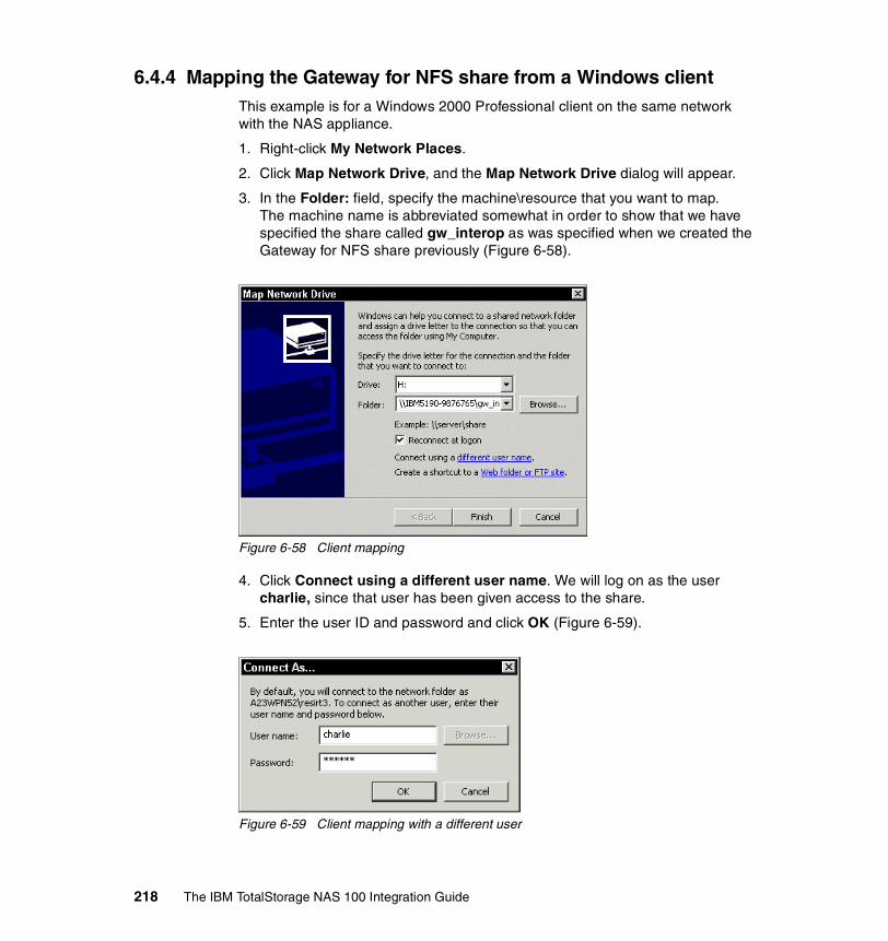
6.4.4 Mapping the Gateway for NFS share from a Windows clientThis example is for a Windows 2000 Professional client on the same network with the NAS appliance.
1. Right-click My Network Places.
2. Click Map Network Drive, and the Map Network Drive dialog will appear.
3. In the Folder: field, specify the machine\resource that you want to map. The machine name is abbreviated somewhat in order to show that we have specified the share called gw_interop as was specified when we created the Gateway for NFS share previously (Figure 6-58).
Figure 6-58 Client mapping
4. Click Connect using a different user name. We will log on as the user charlie, since that user has been given access to the share.
5. Enter the user ID and password and click OK (Figure 6-59).
Figure 6-59 Client mapping with a different user
218 The IBM TotalStorage NAS 100 Integration Guide

6. Then click Finish to create the mapped drive.
When the drive is created, you can access the drive from the Windows Explorer to create new files and folders.
Logon to your UNIX client as user charlie and mount the nfs_interop share that is exported by the NAS appliance. Verify that the files created from the Windows client (Figure 6-60) have the charlie:support ownership (Figure 6-61). Create new files from the UNIX client and verify that the files can be seen from the Windows client.
Figure 6-60 Created testfile2 from Charlie on the shared gw_interop folder
Chapter 6. Cross platform storage 219

Figure 6-61 testfile2 created from charlie:support in Windows on NFS-share
How to enable character translation (Q289627)We discuss the problems that can occur due to different character mapping on Windows and UNIX operating systems. In some cases you may encounter a problem while sharing files between both environments.
There are several restrictions used in Windows and UNIX on valid characters for naming a file. To solve any problem that can relay on an invalid use of characters and character translation, refer to the Microsoft Web site:
http://support.microsoft.com/default.aspx?scid=KB;en-us;289627&
6.4.5 Accessing the shares from our UNIX clientsWe will now explain how to get access to the shares created on the NAS system from the UNIX world.
Accessing the shares from our Linux/Solaris/HP-UX clientsConnecting to the shared disks from our RedHat Linux 8.0 client, dhcp39070, was just as easy. First, we modified the /etc/fstab file to include a listing for the shared disk.
This is shown on the last line in Figure 6-62.
Note: Under Solaris, the /etc/vfstab file is updated, rather than the /etc/fstab.
220 The IBM TotalStorage NAS 100 Integration Guide

Figure 6-62 Adding the NAS’s shared disk to the Linux fstab file
Once that was done, we created a directory named /import and mounted the shared directory /Files to it normally using the mount command, as shown in Figure 6-63. We then changed directory to /import and were immediately able to see all of the data on the shared disk.
Figure 6-63 Mounting the NAS’s shared directory from a Linux client
We opened some of the files and created new ones. This worked beautifully and we were able to see the changes from the Windows clients. As a further test, we created a text file from the Linux client, saved it, and left it open. We then tried accessing the file from one of the Windows clients. While we were able to open the file normally, we were pleased to note that Windows recognized that the file was still in use on the Linux system and did not let us overwrite it.
With a minimum of effort, we were able to use the NAS 100 to safely share storage among heterogeneous LAN/WAN clients.
Chapter 6. Cross platform storage 221

Accessing the shares from our AIX clientsNow we will show you the few commands we used to get AIX ready to use the NAS 200 and 300’s shared disks.
First we needed to update /etc/filesystems. This was accomplished by using the crfs command, as shown in Example 6-2.
Example 6-2 Using the crfs command
# crfs -v nfs -m /nas100 -n ibm5190-9876765 -d nfs_interop -A yes# cat /etc/filesystems/nas100: dev = nfs_interop vfs = nfs nodename = ibm5190-9876765 mount = true account = false
Finally, we mounted the share, as shown in Example 6-3.
Example 6-3 Mounting the share
# mount -v nfs ibm5190-9876765:nfs_interop /nas100# mount node mounted mounted over vfs date options -------- --------------- --------------- ------ ------------ --------------- /dev/hd4 / jfs Nov 11 16:50 rw,log=/dev/hd8 /dev/hd2 /usr jfs Nov 11 16:50 rw,log=/dev/hd8 /dev/hd9var /var jfs Nov 11 16:50 rw,log=/dev/hd8 /dev/hd3 /tmp jfs Nov 11 16:50 rw,log=/dev/hd8 /dev/hd1 /home jfs Nov 11 16:51 rw,log=/dev/hd8 /dev/lv00 /usr/welcome_arcade jfs Nov 11 16:51 rw,log=/dev/hd8 /dev/lv01 /usr/welcome jfs Nov11 16:51 rw,log=/dev/hd8 ibm5190-9876765 nfs_interop /nas100 nfs3 Nov 11 17:17
----------------------------------------------------------------------------------------------------------
6.5 Accessing the shares with the Samba clientSamba is an implementation of the Server Message Block (SMB) protocol, a subset of Common Internet File System (CIFS), that can be run on almost every variant of UNIX in existence. Samba is an open source project just like Linux. The entire code is written in C so it is easily ported to all flavors of UNIX.
In a Windows network, with IBM TotalStorage NAS in place, if you have a Linux host, it can connect to the IBM NAS machine without having additional protocols but CIFS in your network. This will simplify your network setup and maintenance.
222 The IBM TotalStorage NAS 100 Integration Guide
Samba has two components:
Samba server This allows UNIX systems to move into a Windows “Network Neighborhood” in the same way a Windows NT/2000 file server does. With Samba, UNIX servers are acting like any other Windows server, offering their resources to the SMB/CIFS clients.
Samba client This allows Linux or Unix hosts to access any shared directory or printer on Windows NT/2000 servers or Samba servers, by allowing these machines to access Windows files with CIFS/CIFS protocol.
6.5.1 Setting up the Samba client on a RedHat Linux 8.0The Samba client will allow you to take advantage of the Samba File System (SMBFS). With SMBFS you can mount any share from a Windows NT/2000 server or Samba server into your directory structure.
This is available on Linux only, and it gives you two choices about how to access Windows NT/2000 files:
� Mounting a NAS Share into the Linux file system� Using the smbclient program
The first step is to check if Samba is already installed in your system. To do this, query the RPM database:
rpm -q samba
This command will return either the version number of the installed package or a message indicating that the package is not installed. If Samba is not installed, mount the Red Hat 8.0 CD-ROM (Disc 2) and install the following packages:
mount /mnt/cdrom# rpm -ivh /mnt/cdrom/RedHat/RPMS/samba-common-2.2.5-10.i386.rpm# rpm -ivh /mnt/cdrom/RedHat/RPMS/samba-client-2.2.5-10.i386.rpm
6.5.2 Mounting a NAS Share into the Linux file systemWe want to have access from our RedHat 8.0 machine to a file share configured in the IBM TotalStorage NAS 100 named ibm5190-9876765. The share we want to access is named Files.
One-time mountIf we try to mount the share as a user without sufficient rights, we are allowed to do it. But, when accessing the files, permission is denied.
Chapter 6. Cross platform storage 223

#mount -t smbfs -o username=user1,password=pwd1 //ibm5190-9876765/Files /nas100#ls /nas100
We get the following message:
#ls: /nas100: Permission denied
We have to umount the share and mount it again as a user with sufficient rights
#mount -t smbfs -o username=user2,password=pwd2 //ibm5190-9876765/Files /nas100#ls /nas100 #file1 file2
Now, we are able to access and manage the files in //ibm5190-9876765/Files as they were stored in the local Linux host disk.
Permanent mountIf you don’t want to map the share every time you need it, there is a procedure to automatically map it each time the client machine boots.
We included the following line at the end of the /etc/fstab file:
//ibm5190-9876765/Files /nas100 smbfs username=user2,password=pwd2 0 2
There is a better solution if you don’t want to show your password in the /etc/fstab file. A credentials file can be created in your private home directory, so nobody (but root) can read it. Reference this file in /etc/fstab in the following way:
//ibm5190-9876765/Files /nas100 smbfs credentials=/root/credentials_file 0 2
Create a file called credentials_file in the /root directory with the following content:
username = user2password = pwd2¿ domain = XXXXXx ?
Note: The user must be a valid local account on the NAS host or a valid account in the Windows NT/2000 domain.
224 The IBM TotalStorage NAS 100 Integration Guide

6.5.3 Using the smbclient programThe smbclient is an FTP-like client to access SMB/CIFS resources on servers. This client can open a connection to an SMB/CIFS server in the same way as the FTP client does. Using this command we don’t need to mount a share, just establish a connection and talk with the NAS machine.
The command line is as follows:
smbclient {servicename} [password] [options]
All the options are listed in the man pages. The most common options are:
servicename The servicename is the name of the service you want to use on the server. Our case //nas200/fileshare.
password The password required to access the specific share.
-R <name resolve order> This option is used by the programs in the Samba suite to determine what naming services and in what order to resolve host names to IP addresses.
-N If specified, this parameter suppresses the normal password prompt from the client to the user.
-n NetBIOS name By default, the client will use the local machine's hostname (in uppercase) as its NetBIOS name. This parameter allows you to override the host name and use whatever NetBIOS name you wish.
-p port This number is the TCP port number that will be used when making connections to the server. The standard (well-known) TCP port number for an SMB/CIFS server is 139, which is the default.
-l logfilename If specified, logfilename specifies a base filename into which operational data from the running client will be logged.
-h Print the usage message for the client.
-I IP-address IP address is the address of the server to connect to.
-U username[%pass] Sets the SMB username or username and password.
-A filename This option allows you to specify a credentials file.
We can open a connection to fileshare in nas200 without parameters just by issuing the following command:
#smbclient //ibm5190-9876765/Files pwd2 -U user2
Chapter 6. Cross platform storage 225

Once the client is running, and connected you will see a prompt like this:
smb:\>
In this prompt, the backslash (“\”) shows us the current working directory and will change if the current working directory is changed. The prompt indicates that the client is ready and waiting to fulfill a user command. Commands like cd, ls, del, help, mkdir, dir... can be used. You can find a complete list of commands in the man pages of you Linux host.
Commands like get, put, mget, mput allow us to send or retrieve files in the IBM NAS TotalStorage server.
Use the exit command to close the connection.
6.5.4 Samba client configuration on AIX Sometimes, you want to access your Samba server or shares from a Windows machine using AIX. You can use the smbclient program to do this. The smbclient program is a client that can communicate with a SMB/CIFS server. If you have installed Samba using the default path, you will find it in /usr/local/samba/bin. It is a good idea to include this path in your user profile. If you want to do this, you have only to add the following line in your profile:
PATH=$PATH:/usr/local/samba/bin
This client has an interface very similar to the ftp program. You can use smbclient to get files from the server to the local machine, put files from the local machine to the server, retrieve directory information from the server, and so on.
Now that you have set up your profile, you can access your files in the Samba server. You can use some of the options in the command line shown in the screen below.
Example 6-4 Samba client command line interface
added interface ip=9.3.187.230 bcast=9.3.187.255 nmask=255.255.255.0Usage: smbclient service <password> [options]Version 2.0.6 -s smb.conf pathname to smb.conf file -O socket_options socket options to use -R name resolve order use these name resolution services only -M host send a winpopup message to the host -i scope use this NetBIOS scope -N don't ask for a password -n netbios name. Use this name as my netbios name -d debuglevel set the debuglevel -P connect to service as a printer -p port connect to the specified port -l log basename. Basename for log/debug files -h Print this help message.
226 The IBM TotalStorage NAS 100 Integration Guide

-I dest IP use this IP to connect to -E write messages to stderr instead of stdout -U username set the network username -L host get a list of shares available on a host -t terminal code terminal i/o code {sjis|euc|jis7|jis8|junet|hex} -m max protocol set the max protocol level -W workgroup set the workgroup name -T<c|x>IXFqgbNan command line tar
-D directory start from directory -c command string execute semicolon separated commands -b xmit/send buffer changes the transmit/send buffer (default: 65520
If you want to connect to the server without specifying any other parameter, you can use the following command:
smbclient //<Netbios Server Name>/<Service> -U <Username>
You can also use some options to modify the way that you are going to connect to the server. Here are some options:
-N This option is used to suppress the normal password prompt from the client to the user. This option is very useful when you want to access a server that does not require a password to be accessed.
-p This option is used to specify the TCP/IP port that you will use when making connections. The standard TCP/IP port number for a SMB/CIFS server is 139; so, if you do not use this option, your client will try to connect to the server using the 139 port.
-I This option is used to specify the IP address of the Samba server to which you are trying to connect. This is very useful if your client is having problems using the NetBIOS name resolution.
-O This option is used when you want to specify the socket option. Here is a list of the valid options:
• SO_KEEPALIVE• SO_REUSEADDR• SO_BROADCAST• TCP_NODELAY• IPTOS_LOWDELAY• IPTOS_THROUGHPUT• SO_SNDBUF• SO_SNDLOWAT• SO_RCVLOWAT
Note: You can use \\ instead of each / if you wish. You have to use two backslashes for each slash that you want to substitute. The first backslash acts as a character escape for the second one.
Chapter 6. Cross platform storage 227

The last four options take an integer argument.
If you are successful in connecting to the server, you will be prompted for a password. If you enter a valid password, you will see the smbclient prompt as shown in the following screen.
Example 6-5 Samba client connection
# smbclient //lva111a/test -U rootadded interface ip=9.3.187.230 bcast=9.3.187.255 nmask=255.255.255.0Password:Domain=[DOMAIN01] OS=[Unix] Server=[Samba 2.0.6]smb: \>
If you have problems connecting to the server, you can use the -R option before the -U option to specify which name resolution services to use when looking up the NetBIOS name. The options are:
lmhosts: This option will use the Samba lmhosts file. You can find this file in the same directory as the smb.conf file. If you have installed your Samba server using the default path, you will find this on /usr/local/samba/lib.
host: This option uses the /etc/hosts file to resolve the names. This method of name resolution depends on the operating system that you are using.
wins: Use the WINS server set up in the smb.conf file. If you do not have one specified, this method will be ignored
bcast: This option does a broadcast on the interfaces listed in the interfaces parameter in the smb.conf file. This is not a good option to choose because it depends on the target host being on a locally-connected subnet.
Now that you are accessing the Samba server, you can execute the smbclient commands. The following is a list of some smbclient commands that you can use to work with your files:
cd: Changes the current working directory to the specified directory. This operation will fail if the specified directory does not exists or if you do not have access.
dir: List the files in the current working directory. You can also use ls to list files.
mkdir: Create a new directory on the server. You can use also md.
rmdir: Remove a directory from the server. You can use also rd.
228 The IBM TotalStorage NAS 100 Integration Guide

lcd: Change the local machine directory to the one specified. If the specified directory does not exist or if you do not have access to this directory, the operation will fail.
get: Copy the specified file from the current working directory on the server to the client. You can also use the mget command to copy multiple files that match a mask that you specify.
put: Copy the specified file from the current working directory on the local machine to the remote server. You can also use the mput command to copy multiple files that match a mask that you specify.
Del.: Delete all files in the current working directory that match the mask that you specify.You can also use the rm command.
help: Display a brief description of the command, if you have specified one. If not, it will display a list of all available commands. You can use ? instead of using the help command.
lowercase: Toggle the option to get the files from the Samba server only in lowercase.
prompt: Toggle the option for filename prompts during the operation of the mget and mput commands.
recurse: Toggle the directory recursion for the mget and mput commands. When the toggle is on, this option will process all the directories in the source directory and will recourse into any that match the mask specified to the command.
setmode: This option works like the attrib command in DOS. If you want to change the permission of a certain file to read only, you can, for example, use setmode example.txt +r.
exit: This terminates the connection with the server and exits from the smbclient. You can also use quit.
6.5.5 Sources and additional informationYou can find more information on the official Samba project Web site at:
http://www.samba.org
For good how-to documents, see the Linux documentation project home page:
http://www.linuxdoc.org/
Chapter 6. Cross platform storage 229

230 The IBM TotalStorage NAS 100 Integration Guide
Chapter 7. Backup, restore, troubleshooting
In our computing world today, data is considered the most important competitive differentiating factor. Temporary inaccessibility or the complete loss of data has a huge financial impact, and can drive companies out of business. The inability to manage data can have a negative impact on a company’s profitability and limit its ability to grow. Storing, protecting, and managing data growth has become one of the major challenges of today’s businesses.
The NAS 100 units are designed to plug into your current data protection scheme — unlike many NAS appliances, they do not depend on special vendor-provided software, but work with out-of-the-box backup software. If you use Tivoli Storage Manager (TSM) as your enterprise backup solution, you will be pleased to know that the NAS 100 unit is shipped with a TSM client already installed on it.
Also, if you do not already have a data protection scheme in place, the NAS 100 comes bundled with its own complete backup solution. In this chapter we describe various configurations for backing up and restoring the NAS 100, either by using the native backup solution, or by integrating the NAS 100 into an existing TSM environment. We cover these topics:
� The NAS 100 and its native backup solution� Using PSM with backup software solutions� Troubleshooting� Accessing the BIOS� Hard drive failure and recovery scenarios
7
© Copyright IBM Corp. 2003. All rights reserved. 231

7.1 The NAS 100 and its native backup solutionThe NAS 100 units come with a rich set of utilities for data management. One of the key advantages of using the NAS 100 is the ability to capture point-in-time image copies without the need for a long downtime window by means of the Persistent Storage Manager (PSM) software. In the following sections we describe the use of the PSM, and how it can be used in conjunction with NTBackup to help increase productivity in backup and recovery of your mission critical data.
Later in this chapter, we will show how to identify problems on the NAS 100 box using the LEDs along the bottom of the bezel and give some troubleshooting tips. We will also provide information on how to access the NAS 100 BIOS and how to configure it to your needs. Finally, we have arranged some disk and partition failure scenarios to give examples of how to recover the system and your data in the case of a serious breakdown.
7.1.1 NAS 100 backupThe NAS 100 uses two types of backup: point-in-time image copies and archival backup.
Point-in-time backupPoint-in-time images provide a near-instant virtual copy of an entire storage volume. These point-in-time copies are referred to as persistent images and are managed by the Persistent Storage Manager (PSM) software. If PSM is used, 15% of available disk space on each disk partition is reserved for the cache.
Tip: For more information on backup and recovery solutions for IBM TotalStorage NAS appliances, see the IBM Redbook, IBM TotalStorage NAS Backup and Recovery Solutions, SG24-6831, which is available at:
http://www.redbooks.ibm.com/
Note: Point-in-time images are not a backup, but a method for capturing an image to make a backup from.
232 The IBM TotalStorage NAS 100 Integration Guide

These instant virtual copies have the following characteristics:
� Normal reads and writes to the disk continue as usual, as if the copy had not been made.
� Virtual copies are created very quickly and with little performance impact, as the entire volume is not truly copied at that time.
� Virtual copies appear exactly as the original volume when the virtual copy was made.
� Virtual copies typically take up only a fraction of the space of the original volume.
These virtual copies are created very quickly and are relatively small in size. As a result, functions that would otherwise have been too slow, or too costly, are now made possible. Use of these persistent images may allow individual users to restore their own files without any system administrator’s intervention. With the pre-loaded code, the NAS administrator can schedule the PSM to automatically perform an instant virtual copy at regular intervals.
The administrator can also grant end users access to their specific virtual copies. If a particular user accidentally deletes or corrupts a file, he or she can just drag-and-drop the virtual copy of that file to their storage without needing any administrator involvement. If you would like to know more about this topic, please refer to IP Storage Networking: IBM NAS and iSCSI Solutions, SG24-6240-00.
Archival backupArchival backup is used to make full, incremental, or differential backup copies, which are typically stored to tape. A common problem with these backups is that files which were open at the time the backup ran, often fail to get backed up. The NAS 100’s PSM is not hindered by open files, so it can successfully make backup copies in a 24x7 operation. Special precautions must be made to ensure data consistency when continuous write operations occur. Please see 7.2.1, “IBMSNAP utility” on page 234.
7.2 Using PSM with backup software solutionsFor systems that need to be available 24 hours and 7days a week, backup is a challenge. Traditionally, it is required to shut down the application and to close any open files before performing a backup, to ensure data integrity. However, if a significant amount of data is involved, backup may take a while, especially when the transfer is directed to tape. This amount of downtime may not be acceptable for most systems, for various reasons, such as delayed transactions or lost profit.
Chapter 7. Backup, restore, troubleshooting 233
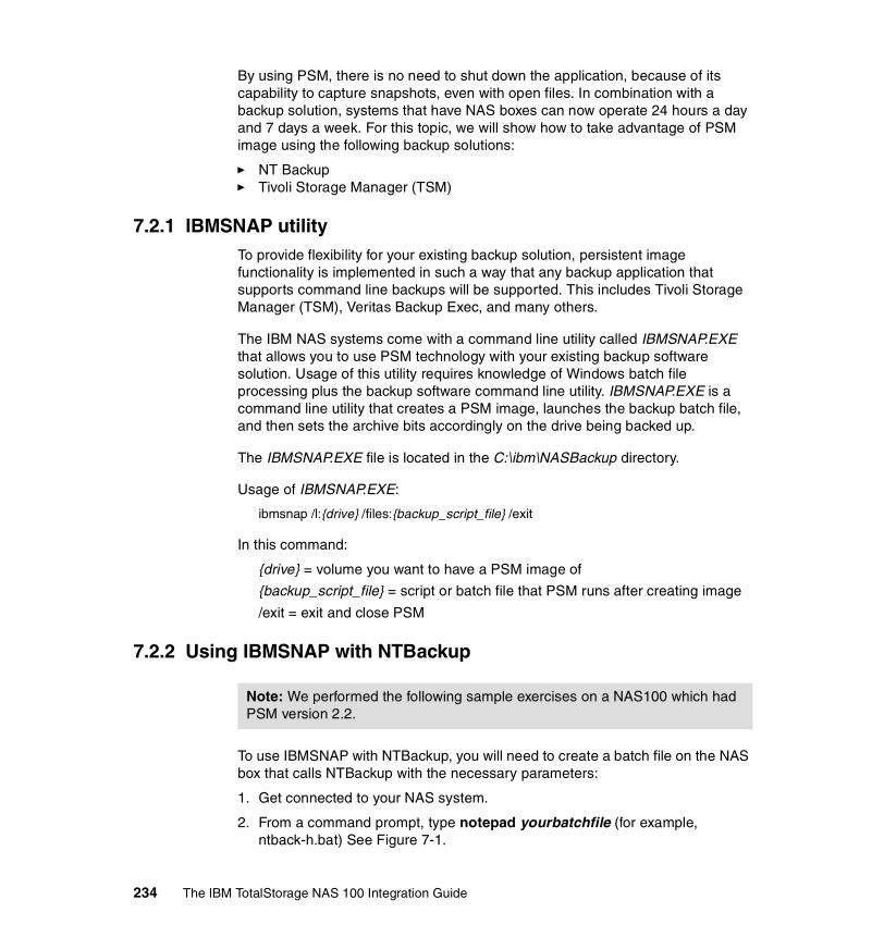
By using PSM, there is no need to shut down the application, because of its capability to capture snapshots, even with open files. In combination with a backup solution, systems that have NAS boxes can now operate 24 hours a day and 7 days a week. For this topic, we will show how to take advantage of PSM image using the following backup solutions:
� NT Backup� Tivoli Storage Manager (TSM)
7.2.1 IBMSNAP utilityTo provide flexibility for your existing backup solution, persistent image functionality is implemented in such a way that any backup application that supports command line backups will be supported. This includes Tivoli Storage Manager (TSM), Veritas Backup Exec, and many others.
The IBM NAS systems come with a command line utility called IBMSNAP.EXE that allows you to use PSM technology with your existing backup software solution. Usage of this utility requires knowledge of Windows batch file processing plus the backup software command line utility. IBMSNAP.EXE is a command line utility that creates a PSM image, launches the backup batch file, and then sets the archive bits accordingly on the drive being backed up.
The IBMSNAP.EXE file is located in the C:\ibm\NASBackup directory.
Usage of IBMSNAP.EXE:
ibmsnap /l:{drive} /files:{backup_script_file} /exit
In this command:
{drive} = volume you want to have a PSM image of
{backup_script_file} = script or batch file that PSM runs after creating image
/exit = exit and close PSM
7.2.2 Using IBMSNAP with NTBackup
To use IBMSNAP with NTBackup, you will need to create a batch file on the NAS box that calls NTBackup with the necessary parameters:
1. Get connected to your NAS system.
2. From a command prompt, type notepad yourbatchfile (for example, ntback-h.bat) See Figure 7-1.
Note: We performed the following sample exercises on a NAS100 which had PSM version 2.2.
234 The IBM TotalStorage NAS 100 Integration Guide

Figure 7-1 Sample batch file calling NTBackup
In this command:
%1 = persistent image virtual drive letter to be supplied by PSM automatically; the drive letter that will be used by PSM is the next available drive on your system
/m = mode (in the example, we selected normal)
/f = the backup file (and its location)
3. Run IBMSNAP (from C:\ibm\NASBackup directory) with the necessary parameters. For example:
ibmsnap /l:e /files:c:\winnt\system32\ntback-e.bat /exit
In this command:
e= drive to be backed up
ntback-e.bat = batch file to execute NTBackup
4. You should see a screen (on the NAS Terminal Services Client session) similar to the one shown in Figure 7-2.
Figure 7-2 Screen showing IBMSNAP running and PSM creating an image
Chapter 7. Backup, restore, troubleshooting 235

After that, NTBackup should start (Figure 7-3).
Figure 7-3 NTBackup started automatically by IBMSNAP
236 The IBM TotalStorage NAS 100 Integration Guide

5. You should next see that the backup is being done, as in Figure 7-4. This screen shows an on-going backup of removable disk F, which contains a PSM image of drive E,
Figure 7-4 On-going backup of removable disk F with PSM image of drive H
Chapter 7. Backup, restore, troubleshooting 237

6. Once the backup is completed, you will be returned to the command prompt. It should display a screen similar to the one in Figure 7-5, showing that IBMSNAP and NTBackup have completed successfully.
Figure 7-5 Successful completion of IBMSNAP and NTBackup
238 The IBM TotalStorage NAS 100 Integration Guide

7. You can check if the backup file has been created (Figure 7-6).
Figure 7-6 Screen showing the backup file created
8. Notice also that there is the Removable Disk (F:) on the NAS as shown in Figure 7-6. This is the temporary location to which the persistent image was stored by PSM for the NTBackup purpose. Drive F: was used because it is the next available drive.
While the backup takes place, you should be able to access the removable disk. But once it has completed and IBMSNAP has finished, this removable disk is no longer accessible. To release the removable disk, you should logoff and logon to your system.
Chapter 7. Backup, restore, troubleshooting 239

7.2.3 Creating a scheduled NT backup with IBMSNAPIf you want to schedule the creation of a persistent image and then back it up, you need to create two batch files, one that calls IBMSNAP at the scheduled time, and the other calls NTBackup. Then you need to use the Windows AT command to create an entry on the Task Scheduler to call the IBMSNAP batch file at your specified time.
Here is an example:
1. Create a batch file that calls IBMSNAP (Figure 7-7).
Figure 7-7 Sample batch file that calls IBMSNAP
2. Create the batch file called by IBMSNAP, which in turn calls NTBackup (Figure 7-8).
Figure 7-8 Sample batch file that calls NTBackup
3. On the NAS command prompt, type: at time “ibmsnap_batch_file”, for example:
at 11:00pm “c:\winnt\system32\backup-e.bat”
4. You should see that the job is added to Task Scheduler with a specific job ID. To confirm, at the command prompt, type at (see Figure 7-9).
240 The IBM TotalStorage NAS 100 Integration Guide
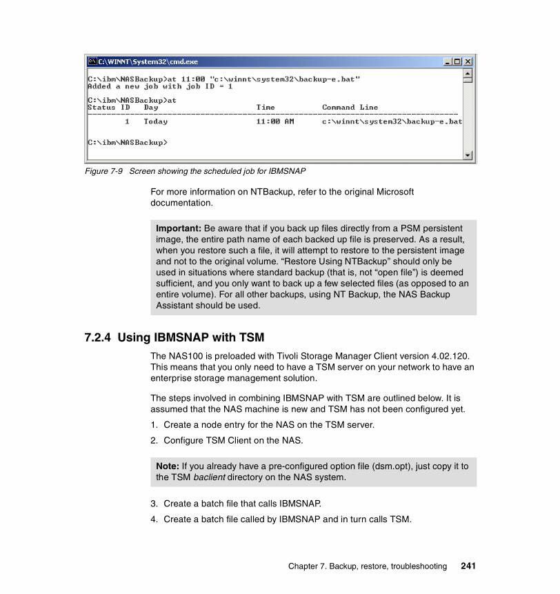
Figure 7-9 Screen showing the scheduled job for IBMSNAP
For more information on NTBackup, refer to the original Microsoft documentation.
7.2.4 Using IBMSNAP with TSMThe NAS100 is preloaded with Tivoli Storage Manager Client version 4.02.120. This means that you only need to have a TSM server on your network to have an enterprise storage management solution.
The steps involved in combining IBMSNAP with TSM are outlined below. It is assumed that the NAS machine is new and TSM has not been configured yet.
1. Create a node entry for the NAS on the TSM server.
2. Configure TSM Client on the NAS.
3. Create a batch file that calls IBMSNAP.
4. Create a batch file called by IBMSNAP and in turn calls TSM.
Important: Be aware that if you back up files directly from a PSM persistent image, the entire path name of each backed up file is preserved. As a result, when you restore such a file, it will attempt to restore to the persistent image and not to the original volume. “Restore Using NTBackup” should only be used in situations where standard backup (that is, not “open file”) is deemed sufficient, and you only want to back up a few selected files (as opposed to an entire volume). For all other backups, using NT Backup, the NAS Backup Assistant should be used.
Note: If you already have a pre-configured option file (dsm.opt), just copy it to the TSM baclient directory on the NAS system.
Chapter 7. Backup, restore, troubleshooting 241

5. Execute an automated TSM backup of the persistent image by running the batch file that calls IBMSNAP.
Creating a Node entry for the NAS on the TSM ServerThese are the steps for creating a Node entry for the NAS on the TSM Server:
1. Open the Web Admin on your TSM Server.
2. Logon using the administrative account.You will get the Welcome screen(Figure 7-10).
Figure 7-10 TSM Server Welcome screen
Important: It is important for the NAS100 that the snapshot with IBMSNAP has to be configured to be taken automatically by a certain time like it is shown in “Creating a scheduled TSM backup using IBMSNAP” on page 257. This function will not work over a terminal services session when you do the snapshot manually!
242 The IBM TotalStorage NAS 100 Integration Guide

3. On the main screen, click Operation View (Figure 7-11).
Figure 7-11 TSM Server Operation View
4. Under Operation View, select Work with client nodes (Figure 7-12).
Figure 7-12 TSM Work with client nodes window
Chapter 7. Backup, restore, troubleshooting 243

5. Register a new node.
6. Fill in the necessary information for the new node as shown in Figure 7-13, and click Finish.
Figure 7-13 TSM server administration for the new node
Note: For a detailed information on TSM and each option under the “Register a new node” window, please refer to the redbook, Getting Started with Tivoli Storage Manager: Implementation Guide, SG24-5416.
244 The IBM TotalStorage NAS 100 Integration Guide

7. You will get the operation results on the server’s GUI (Figure 7-14).
Figure 7-14 TSM operations result screen
Configuring a TSM Client on the NASThese are the steps for configuring a TSM Client on the NAS:
1. Open your TSM Backup Client GUI.
2. On the TSM Client Configuration Wizard, select the options you want to configure by checking the appropriate boxes. Then click Next (Figure 7-15).
Figure 7-15 TSM Client Configuration Wizard
Chapter 7. Backup, restore, troubleshooting 245
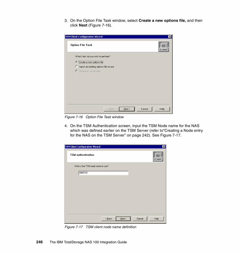
3. On the Option File Task window, select Create a new options file, and then click Next (Figure 7-16).
Figure 7-16 Option File Task window
4. On the TSM Authentication screen, input the TSM Node name for the NAS which was defined earlier on the TSM Server (refer to“Creating a Node entry for the NAS on the TSM Server” on page 242). See Figure 7-17.
Figure 7-17 TSM client node name definition
246 The IBM TotalStorage NAS 100 Integration Guide

5. On the TSM Client/Server Communications, select the appropriate protocol for your network. In this case, we select TCP/IP. Then click Next (Figure 7-18).
Figure 7-18 TSM client protocol selection
Chapter 7. Backup, restore, troubleshooting 247

6. On the TCP/IP Parameters screen, type in the IP address of your TSM server. If you have not changed the default TCP/IP port on the TSM server (which is 1500), just accept the default. Otherwise, change it to match that on the TSM server. Then click Next (Figure 7-19).
Figure 7-19 TSM client TCP/IP parameters window
7. On the Domain and include/exclude lists, click Edit to modify the default values. Otherwise, click Next (Figure 7-20).
A user can define an include-exclude list to specify which files are eligible for backup services, which files can be migrated from the client (space-managed), and how the server manages backed-up, archived, and space-managed files.
If a user does not create an include-exclude list, the following default conditions apply:
– All files belonging to the user are eligible for backup services.
– The default management class governs backup, archive, and space-management policies.
248 The IBM TotalStorage NAS 100 Integration Guide

Figure 7-20 TSM client domain include/exclude lists
8. On the last screen of the configuration wizard, click Finish (Figure 7-21).
Figure 7-21 TSM client final window
Chapter 7. Backup, restore, troubleshooting 249

9. A login screen will appear (Figure 7-22).
Figure 7-22 TSM login screen
10.Now the TSM GUI will be opened on your NAS 100 box (Figure 7-23).
Figure 7-23 TSM Client GUI
Creating the batch file that calls IBMSNAPThe procedure for running the IBMSNAP is independent of the backup solution (whether NTBackup, TSM, or any other that supports the command line utility). However, for simplification of scheduling the TSM backup of the PSM image, we will create a batch file that executes the IBMSNAP command.
250 The IBM TotalStorage NAS 100 Integration Guide

Here is the procedure:
1. On a command prompt, type Notepad batch_file”. For example:
notepad tsmbackup-i.bat
2. Enter the IBMSNAP command with appropriate parameters. Refer to 7.2.1, “IBMSNAP utility” on page 234 for the available parameters and their usage. Save and close Notepad (Figure 7-24).
Figure 7-24 Sample IBMSNAP batch file
Creating a batch file that calls TSMTSM has the “dsmc.exe” utility that enables the command line backup execution. However, to run properly, it has to be executed within the \baclient subdirectory. Therefore, the change directory entry has to be added on the batch file.
Unlike NTBackup, TSM uses volume labels to keep track of the drives on the machine. It is therefore important to have unique volume labels on the NAS. This reveals a problem, since IBMSNAP uses the volume label of the source drive for the volume label of the temporary Removable Disk that it creates. For example, suppose your NAS drives are the following:
Table 7-1 Sample NAS disk configuration
While using IBMSNAP, you create a persistent image of E: whose volume label is HAWK1, a temporary Removable Disk will be created by IBMSNAP whose drive letter will be F: (since it is the first available letter), and will assign the volume label HAWK1. So, as far as TSM is concerned, you have two volumes (drives E: and F:) with the same label. If you back up F: (which the batch files do), the process will fail. It is very important, therefore, that you rename the temporary Removable Disk before the TSM backup runs. This can be done by adding a label command on your batch file.
Drive Letter Volume Label
C: Primary OS
D: Backup OS
E: HAWK1 (Data)
Chapter 7. Backup, restore, troubleshooting 251
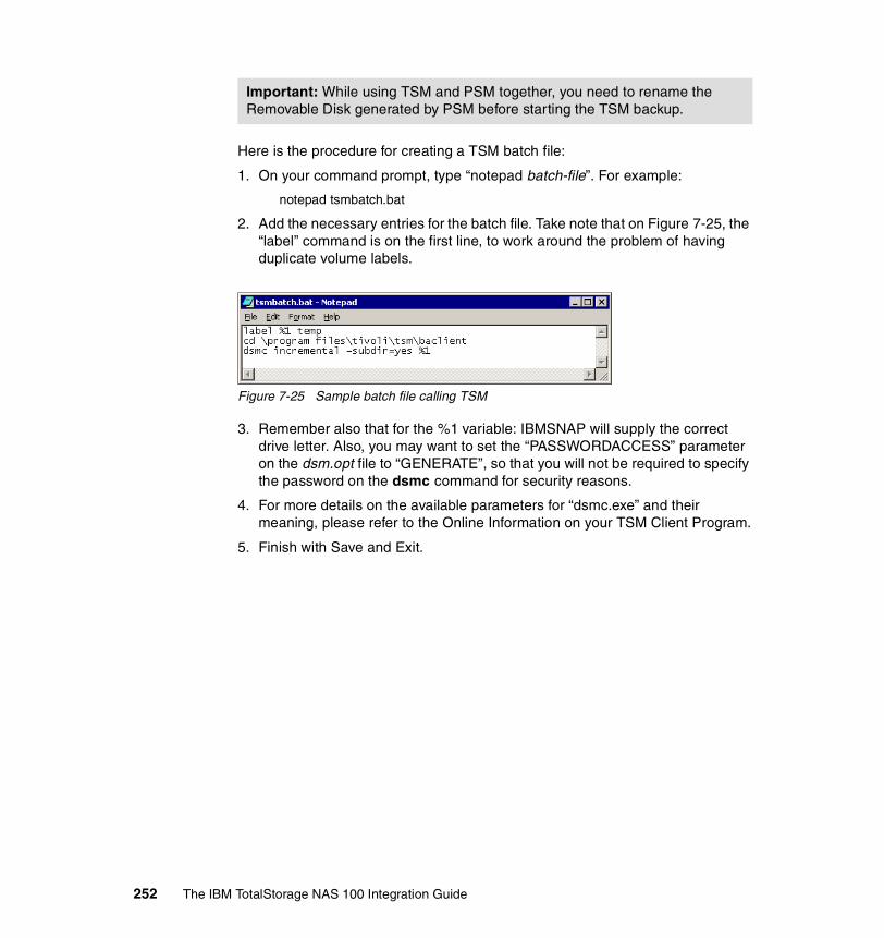
Here is the procedure for creating a TSM batch file:
1. On your command prompt, type “notepad batch-file”. For example:
notepad tsmbatch.bat
2. Add the necessary entries for the batch file. Take note that on Figure 7-25, the “label” command is on the first line, to work around the problem of having duplicate volume labels.
Figure 7-25 Sample batch file calling TSM
3. Remember also that for the %1 variable: IBMSNAP will supply the correct drive letter. Also, you may want to set the “PASSWORDACCESS” parameter on the dsm.opt file to “GENERATE”, so that you will not be required to specify the password on the dsmc command for security reasons.
4. For more details on the available parameters for “dsmc.exe” and their meaning, please refer to the Online Information on your TSM Client Program.
5. Finish with Save and Exit.
Important: While using TSM and PSM together, you need to rename the Removable Disk generated by PSM before starting the TSM backup.
252 The IBM TotalStorage NAS 100 Integration Guide

Executing automated TSM backup of persistent imageNow that everything is prepared, we can run the automated TSM backup of persistent images. Here are the steps:
1. On a command prompt, execute the batch file that calls IBMSNAP (Figure 7-26). For example:
tsmbackup-e.bat
Figure 7-26 Screen right after running IBMSNAP batch file
Chapter 7. Backup, restore, troubleshooting 253

2. PSM will then run and create a snapshot of the specified volume on the batch file. Also, the screen should show that the Removable Disk volume label has been changed to avoid duplication with the source volume (Figure 7-27).
Figure 7-27 Commands and file list of the TSM backup session
3. TSM backup will then proceed.
254 The IBM TotalStorage NAS 100 Integration Guide
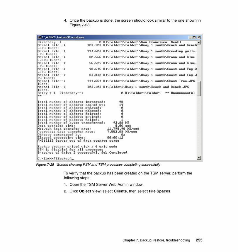
4. Once the backup is done, the screen should look similar to the one shown in Figure 7-28.
Figure 7-28 Screen showing PSM and TSM processes completing successfully
To verify that the backup has been created on the TSM server, perform the following steps:
1. Open the TSM Server Web Admin window.
2. Click Object view, select Clients, then select File Spaces.
Chapter 7. Backup, restore, troubleshooting 255

3. Our sample is shown in Figure 7-29.
Figure 7-29 TSM Web Admin screen showing the backups available
4. Click the backup you just created to display the details, as shown in Figure 7-30.
Figure 7-30 Screen showing the backup details
You now have the confirmation that the TSM backup from the NAS client was successful.
256 The IBM TotalStorage NAS 100 Integration Guide
7.2.5 Creating a scheduled TSM backup using IBMSNAPJust as when working with NTBackup, you need to use the at command utility of Windows 2000 to schedule the start of PSM and TSM. For example, you want to schedule a backup of I: drive’s persistent image at 5pm, you need to execute on a command prompt the following command:
at 5pm “c:\ibm\nasbackup\tsmbackup-e.bat”
In this command:
tsmbackup-e.bat = batch file that calls IBMSNAP
7.3 TroubleshootingThis chapter provides basic troubleshooting information to help you resolve common problems that might occur with your appliance. The following tools are available to help you identify and resolve hardware-related problems:
� Error messages: Error messages and logs indicate successful test completion or the detection of a problem. See “Error messages” on page 258 for more information.
� Temperature checkout: Cooling of the system is important for correct operation and system reliability. See “Temperature checkout” on page 258 for more information.
� LEDs: The LEDs help you identify problems with appliance components. See “Identifying problems using LEDs” on page 259 for more information.
� SCSI adapter test: This procedure tests the SCSI adapter of your appliance. See “SCSI adapter test” on page 264 for more information.
� Accessing the BIOS: Corrupted CMOS data can prevent the appliance from booting or connecting to the network. Resetting the BIOS to its default value can correct the problem. Because of the complexity and importance of the BIOS access we created a separate section for it. See 7.4, “Accessing the BIOS” on page 267.
� Maintenance tools: These commands are for maintenance purposes only. See “Maintenance tools” on page 266 for more information.
Chapter 7. Backup, restore, troubleshooting 257

7.3.1 Error messagesAll error messages and logs are recorded in the Windows event log.
Perform the following steps to access hardware errors in the Windows event log by means of Terminal Services:
1. From the Start menu in the PC task bar, click Program —> Administrator Tools —> Event Viewer.
2. From the Tree panel on the left, click Application Log.
3. Click View —> Filter.
4. Type NAS100Svc in the Event Source field and click OK. The Windows event log opens.
7.3.2 Temperature checkoutCooling of the system is important for correct operation and system reliability. Make sure that:
� Each of the drive bays has a drive installed.
� The top cover is in place during normal operation.
� There is at least 50 mm (2 in.) of ventilated space at the sides of the appliance and 100 mm (4 in.) at the back of the appliance.
� A removed hot-swap drive is replaced within 2 minutes of removal.
� The fans are operating correctly and the air flow is good.
Note: If you receive a critical-level message, you must take action. If the critical message reports a HDD failure, see “Hard disk drive LED problem determination” on page 262. For all other critical-level messages, call the IBM Support Center.
258 The IBM TotalStorage NAS 100 Integration Guide

7.3.3 Identifying problems using LEDsThe NAS 100 has three types of LEDs to help you identify problems with hardware failure and some software errors and system status. Two types of LEDs are located on the front bezel and the third type is located on the back of the chassis:
� System status LEDs are located on the operator information panel near the power button.
� Hard disk drive (HDD) status LEDs are located along the bottom of the bezel.
� Ethernet port status LEDs are located on top of the Ethernet ports (LAN 1 and LAN 2).
Table 7-2 describes the system status LEDs, Table 7-3 on page 261 describes the hard disk drive status LEDs, andTable 7-4 on page 262 describes the Ethernet port status LEDs.
Operator panel LEDsSystem status LEDs are located on the operator information panel near the power button.
Table 7-2 Operator panel LEDs
Symbol Function Color Description Action
Power Green steady AC and DC power on.
No action is necessary.
Green blinking AC Power on and DC power off.
System on standby. Push the power button to switch on the system.
No light AC power unavailable.
Connect the power cable.
Chapter 7. Backup, restore, troubleshooting 259
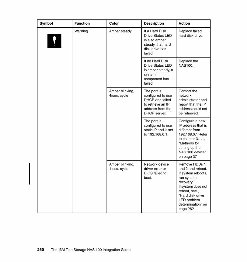
Warning Amber steady If a Hard Disk Drive Status LED is also amber steady, that hard disk drive has failed.
Replace failed hard disk drive.
If no Hard Disk Drive Status LED is amber steady, a system component has failed.
Replace the NAS100.
Amber blinking, 4/sec. cycle
The port is configured to use DHCP and failed to retrieve an IP address from the DHCP server.
Contact the network administrator and report that the IP address could not be retrieved.
The port is configured to use static IP and is set to 192,168.0.1.
Configure a new IP address that is different from 192.168.0.1 Refer to chapter 3.1.1, “Methods for setting up the NAS 100 device” on page 37
Amber blinking, 1-sec. cycle
Network device driver error or BIOS failed to boot.
Remove HDDs 1 and 2 and reboot. If system reboots, run system recovery.If system does not reboot, see , “Hard disk drive LED problem determination” on page 262
Symbol Function Color Description Action
260 The IBM TotalStorage NAS 100 Integration Guide

Hard disk drive LEDsHDD status LEDs are located on the front of the chassis, along the bottom of the
bezel.
Table 7-3 Hard disk drive LEDs
LAN 1 Green steady Link OK. No action is necessary.
LAN 2 Green steady. Link OK. No action is necessary.
Symbol Function Color Description Action
Location Function Color Description Action
Left Status Green steady OK. No action is necessary.
Green/amber blinking, 4/sec., on all drives in array
RAID rebuilding. No action is necessary.
Green/amber blinking, 1-sec. cycle
OS booting from a HDD other than HDD1.
See , “Hard disk drive LED problem determination” on page 262
Green/amber blinking, 2-sec. cycle, on the three drives that need to be rebuilt
RAID needs to be rebuilt to provide fault tolerance.
Rebuild the RAID. Refer to 2 on page 297
Amber steady Hard disk drive failure.
See , “Hard disk drive LED problem determination” on page 262
Right Access Amber steady System is accessing the HDD for data.
No action is necessary.
Chapter 7. Backup, restore, troubleshooting 261
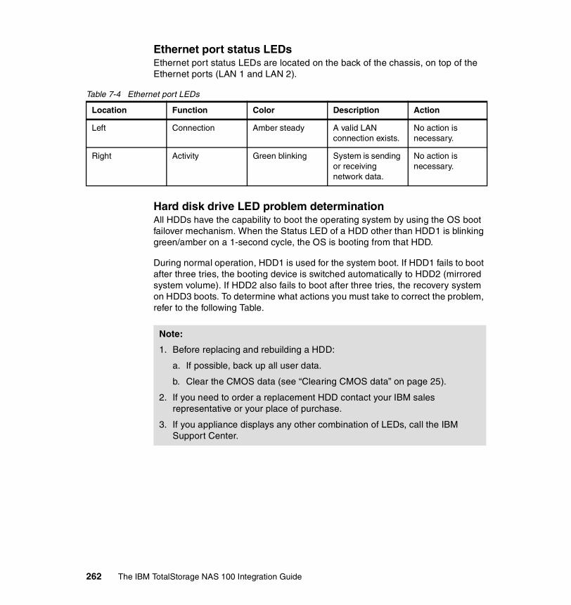
Ethernet port status LEDsEthernet port status LEDs are located on the back of the chassis, on top of the Ethernet ports (LAN 1 and LAN 2).
Table 7-4 Ethernet port LEDs
Hard disk drive LED problem determinationAll HDDs have the capability to boot the operating system by using the OS boot failover mechanism. When the Status LED of a HDD other than HDD1 is blinking green/amber on a 1-second cycle, the OS is booting from that HDD.
During normal operation, HDD1 is used for the system boot. If HDD1 fails to boot after three tries, the booting device is switched automatically to HDD2 (mirrored system volume). If HDD2 also fails to boot after three tries, the recovery system on HDD3 boots. To determine what actions you must take to correct the problem, refer to the following Table.
Location Function Color Description Action
Left Connection Amber steady A valid LAN connection exists.
No action is necessary.
Right Activity Green blinking System is sending or receiving network data.
No action is necessary.
Note:
1. Before replacing and rebuilding a HDD:
a. If possible, back up all user data.
b. Clear the CMOS data (see “Clearing CMOS data” on page 25).
2. If you need to order a replacement HDD contact your IBM sales representative or your place of purchase.
3. If you appliance displays any other combination of LEDs, call the IBM Support Center.
262 The IBM TotalStorage NAS 100 Integration Guide

Table 7-5 HDD LED problem determination
Warning LED HDD1 Status LED
HDD2 Status LED
HDD3 Status LED
HDD4 Status LED
Action
Off Green Green Green Green No action is necessary
Off Green Green Green/amber blinking, 1-sec. cycle
Green Run system recovery.
Off Green Green Green Green/amber blinking, 1-sec. cycle
Call the IBM Support Center.
Amber steady Amber Green/amber blinking, 2-sec. cycle
Green/amber blinking, 2-sec. cycle
Green/amber blinking, 2-sec. cycle
Replace HDD1.
Amber steady Green/amber blinking, 2-sec. cycle
Amber Green/amber blinking, 2-sec. cycle
Green/amber blinking, 2-sec. cycle
Replace HDD2.
Amber steady Green/amber blinking, 2-sec. cycle
Green/amber blinking, 2-sec. cycle
Amber Green/amber blinking, 2-sec. cycle
Replace HDD3.
Amber steady Green/amber blinking, 2-sec. cycle
Green/amber blinking, 2-sec. cycle
Green/amber blinking, 2-sec. cycle
Amber Replace HDD4.
Amber steady Amber Amber Green/amber blinking, 1-sec. cycle
Green/amber blinking, 2-sec. cycle
Call the IBM Support Center.
Amber steady Green/amber blinking, 2-sec. cycle
Amber Green/amber blinking, 1-sec. cycle
Green/amber blinking, 2-sec. cycle
Replace HDD2.
Amber steady Amber Green/amber blinking, 2-sec. cycle
Green/amber blinking, 1-sec. cycle
Green/amber blinking, 2-sec. cycle
Replace HDD1.
Amber steady Amber Amber Green/amber blinking, 1-sec. cycle
Amber Call the IBM Support Center. See Note.
Chapter 7. Backup, restore, troubleshooting 263

SCSI adapter testBefore starting this procedure, check the following hardware and make sure that:
� The SCSI adapter is physically installed in the PCI expansion slot.
� The SCSI cable is correctly connected between the SCSI adapter connector and the tape device.
� The tape device is powered on and no error shows on the tape device’s control panel.
Now proceed as follows:
1. Access the NAS 100 by means of Windows Terminal Services.
2. Click Start —> Settings —> Control Panel. The Control Panel window opens.
3. Double-click System. The System Properties window opens.
4. Click the Hardware tab, and then click Device Manager. The Device Manager window opens.
Amber steady Green/amber blinking, 2-sec. cycle
Amber Green/amber blinking, 1-sec. cycle
Amber Replace HDD2 and HDD4. See Note.
Amber steady Amber Green/amber blinking, 2-sec. cycle
Green/amber blinking, 1-sec. cycle
Amber Replace HDD1 and HDD4. See Note.
Amber steady Green/amber blinking, 2-sec. cycle
Green/amber blinking, 2-sec. cycle
Amber Green/amber blinking, 1-sec. cycle
Call the IBM Support Center.
Amber blinking, 1-sec. cycle
Amber Amber Amber Amber Call the IBM Support Center.
Amber blinking, 1-sec. cycle
Green Green Green Green Call the IBM Support Center.
Warning LED HDD1 Status LED
HDD2 Status LED
HDD3 Status LED
HDD4 Status LED
Action
Note: Your user data is already lost at this point.
264 The IBM TotalStorage NAS 100 Integration Guide

5. Double-click SCSI and RAID controllers.
6. If you:
– Are able to locate Symbios Ultra3 PCI Adapter; 53C1010-66 Device, continue with step 7.
– Cannot locate Symbios Ultra3 PCI Adapter; 53C1010-66 Device, go to step 10 on page 265.
7. Make sure that there is no error mark on Symbios Ultra3 PCI Adapter; 53C1010-66 Device. If there is, either the SCSI adapter or the system board is defective. Contact your IBM service representative for further action.
8. If you want more information, double-click Symbios Ultra3 PCI Adapter; 53C1010-66 Device, click the General tab, and check the message This device is working properly. in the Device Status window.
9. Go to step 12.
10.Click SCSI and RAID controllers, and then click Action —> Scan for hardware changes to install the correct device driver.
11.If the device is not working correctly, click the device and click Action —> Enable to enable the device. If the device still does not work, either the SCSI adapter or the system board is defective. Contact your IBM service representative for further action. Otherwise, continue with step 12.
12.In the Device Manager window, double-click Tape drives.
13.If you:
– Locate IBM XXXXXX-XXX SCSI Sequential Device, where XXXXXX-XXX is the name of the tape device, continue with step 14.
– Cannot locate IBM XXXXXX-XXX SCSI Sequential Device, go to step 17.
14.Make sure that there is no error mark on IBM XXXXXX-XXX SCSI Sequential Device. If there is, either the SCSI adapter, the SCSI cable, or the tape device is defective. Contact your IBM service representative for further action.
15.If you want more information, double-click IBM XXXXXX-XXX SCSI Sequential Device, click the General tab, and check the message This device is working properly. in the Device Status window.
16.Go to step 19.
17.Click SCSI and RAID controllers, and then click Action —> Scan for hardware changes to install the correct device driver.
Note: The location of this device must be PCI bus 1, device 13, and function 0
Chapter 7. Backup, restore, troubleshooting 265

18.If the device is not working correctly, click the device and click Action —> Enable to enable the device. If the device still does not work, either the SCSI adapter, the SCSI cable, or the tape device is defective. Contact your IBM service representative for further action.
19.If both devices are working correctly, the SCSI adapter is working normally. If the hardware tests complete successfully, but the problem persists during normal appliance operations, a software error might be the cause. If you suspect a software problem, refer to the IBM TotalStorage NAS 100 User’s Reference, included on the documentation CD.
Maintenance toolsUse the following commands for maintenance purposes only.
bootchg commandThis command changes the boot order of the HDDs on Windows Powered OS.
1. Access the NAS 100 by means of Windows Terminal Services.
2. Click Start —> Program —> Accessories —> Command Prompt. The Command Prompt window opens.
3. At the prompt, type cd \ibm\nas100 and press Enter.
4. Type bootchg [r] [0-3] [q], where
– r is read current boot order
– 0-3 is set boot disk (0: HDD1 - 3: HDD4)
– q is quiet mode
Now press Enter.
configCMOS commandThis command sets the PXE boot to enable or disable on Windows Powered OS.
1. Access the NAS 100 by means of Windows Terminal Services.
2. Click Start —> Program —> Accessories —> Command Prompt. The Command Prompt window opens.
3. At the prompt, type cd \ibm\nas100 and press Enter.
4. Type configCMOS pxe=[e/d/r] [q], where
– e is set PXE boot enable– d is set PXE boot disable– r is read current PXE boot setting– q is quiet mode
Now press Enter.
266 The IBM TotalStorage NAS 100 Integration Guide

7.4 Accessing the BIOSIn some cases it will be important to access the BIOS of the NAS100. Because it is a headless device the only way to access the BIOS is via RS232 (COM) and Hyperterminal. In this chapter we will give useful information how to handle the BIOS and configure it to your needs.
7.4.1 Clearing CMOS dataClearing the CMOS data resets all the system counters and so usually is not recommended. However, if the CMOS data in the NAS 100 is corrupted, the appliance might not boot up or connect to the network. In this case, resetting the CMOS data can solve the problem. You can also use this procedure to reset the supervisor password if it is lost.
The Clear CMOS button is located in a small hole to the right of the LAN 2 port on the back of the chassis. You can press it by using a pointed implement, such as a paper clip.
Figure 7-31 Clear CMOS button (1)
To reset the CMOS data:
1. If the appliance is rack-mounted:
a. If necessary, remove it from the rack and place it on a level, stable surface
c. Reconnect the appliance.
d. Power on the appliance.
2. Simultaneously press both the Power button on the front of the chassis and the Clear CMOS button on the back of the chassis for one second.
Attention: Before removing the appliance from the rack:
a. Power off the appliance
b. Disconnect the power cord and all cables from the appliance.
Chapter 7. Backup, restore, troubleshooting 267

3. Release the Power button, but keep pressing the Clear CMOS button until a beep sounds (about 10 seconds). This clears the CMOS data and reloads the BIOS to its default value.
4. After you clear the CMOS data, reset the date, time, and, if appropriate, the supervisor password in the BIOS. See “Security” on page 286.
7.4.2 Preparing to use the remote BIOS setting functionThe NAS 100 is a “headless” appliance; it does not have a keyboard, mouse, or monitor directly attached to the appliance. Therefore, to access the BIOS you must have a PC loaded with Windows 2000 and ServicePack2.
1. Power off your appliance.
2. Connect the COM port of the PC to the serial port of the appliance using a 9-pin serial cable (RS-232C female crossover cable). See Table for the signal and pin assignments
Table 7-6 RS-232C female crossover cable
Note: If you press the Power button for more than four seconds, the appliance will power off.
Note: When you clear CMOS data, the supervisor password is reset to the default of 001san (not case-sensitive).
Pin number Signal name
1 Data carrier detect
2 Receive data
3 Transmit data
4 Data terminal ready
5 Signal ground
6 Data set ready
7 Request to send
8 Clear to send
9 Ring indicator
268 The IBM TotalStorage NAS 100 Integration Guide

3. Open HyperTerminal on your PC by clicking Start —> Program —> Accessories —> Communications —> HyperTerminal. The HyperTerminal start window (Figure 7-32) will appear.
Figure 7-32 HyperTerminal start screen
4. After that the Connection Description window opens (Figure 7-33).
Figure 7-33 Connection description window
Chapter 7. Backup, restore, troubleshooting 269

5. Type a name for the connection and then click OK. The Connect To window opens (Figure 7-34).
Figure 7-34 Connect o window
6. Click the COM port that has the serial cable attached (COM1-4) in the Connect using field and click OK. The COM Properties window opens (Figure 7-34).
270 The IBM TotalStorage NAS 100 Integration Guide

Figure 7-35 COM properties window
7. Select the following values in the Properties window:
– Bits per second: 115200– Data bits: 8– Parity: None– Stop bits: 1– Flow control: Hardware
Now click OK. The HyperTerminal window opens (Figure 7-36).
Chapter 7. Backup, restore, troubleshooting 271

Figure 7-36 HyperTerminal window with pull down menu to properties
8. Click File —> Properties. The Properties window opens ().
Figure 7-37 Property window
272 The IBM TotalStorage NAS 100 Integration Guide

9. Enable the function keys of HyperTerminal by clicking the Settings tab, making sure that the radio button for the Terminal keys option is selected, and then clicking OK. The HyperTerminal window opens again.
10.Click Call —> Wait for a call (Figure 7-38).
Figure 7-38 Wait for call tab
11.If you want to:
– Upgrade the BIOS, go to step 4 on page 294.– Update the BIOS, continue with step12.
12.Power on the appliance.
Chapter 7. Backup, restore, troubleshooting 273

13.BIOS POST messages should appear on the HyperTerminal screen (Figure 7-39).
Figure 7-39 Remote BIOS flash access
274 The IBM TotalStorage NAS 100 Integration Guide

14.When the message Press F1 to enter setup opens, press F1 (Figure 7-40).
Figure 7-40 F1 to enter setup
Note: If the messages do not appear:� Check the settings and try again.� Terminate the HyperTerminal program start the procedure again.� Ensure that the serial cable meets the correct specifications.� Ensure that Windows 2000 is correctly installed.
Chapter 7. Backup, restore, troubleshooting 275

15.The appliance will detect its hard disks (Figure 7-41).
Figure 7-41 Detected disks
276 The IBM TotalStorage NAS 100 Integration Guide

16.Now the ethernet adapters are shown (Figure 7-42).
Figure 7-42 Detecting ethernet adapters
Chapter 7. Backup, restore, troubleshooting 277

17.The message Enter current password opens (Figure 7-43). Type the password and press Enter.
Figure 7-43 Entering Setup password
Note: The default password is 001san (not case-sensitive).
278 The IBM TotalStorage NAS 100 Integration Guide

18.The BIOS setup window opens (Figure 7-44).
Figure 7-44 BIOS Main screen
19.Continue with “Making changes to the BIOS”.
Note: In the BIOS setup window, the following function keys are disabled:– F7– F8– F9– F10– Page Up– Page Down
Chapter 7. Backup, restore, troubleshooting 279

7.4.3 Making changes to the BIOSUse the right and left arrow keys to move the cursor between the tabs.
1. Select one of the following tabs in the BIOS setup window.
– Main– Advanced– Chipset/Power/Boot– Boot– Security– Exit
MainThe Main window displays some system information and provides the means to set Date/Time. When you have cleared the CMOS data (see “Clearing CMOS data” on page 267), you must reset Date/Time.
Setting System Time1. Type the appropriate numbers in the Time, Minutes, and Seconds fields. You
can use the Tab key to move through the fields. You can modify the values in white.
2. Use the up and down arrow keys to move the cursor between the System Time and System Date fields.
Setting System Date1. Type the appropriate numbers in the Date (Month), Day, and Year fields. You
can use the Tab key to move through the fields. You can modify the values in white.
2. Press Enter. The day of the week field is set automatically.
Attention: Be very careful when changing BIOS settings. Incorrect settings might cause the system to malfunction. Change only the following items.
Note: Use two-digit numbers for the Date (Month), and Day fields a four-digit number for the Year field (for example, 04/12/2003).
280 The IBM TotalStorage NAS 100 Integration Guide

Advanced1. Use the arrow keys to move the cursor to VPD Data Configuration
(Figure 7-45).
Figure 7-45 BIOS advanced screen
The VPD Data Configuration window opens, displaying the following VPD data:
� BIOS build date� BIOS ID� Machine type� Model name� Machine serial number� Original machine serial number� System part number� Motherboard serial number� Universal Unique ID (UUID)
You can change the machine serial number.
Attention: Although the Advanced window displays six items that can be changed, do not select any configuration except VPD Data Configuration.
Attention: Do not change any other settings in this window.
Chapter 7. Backup, restore, troubleshooting 281
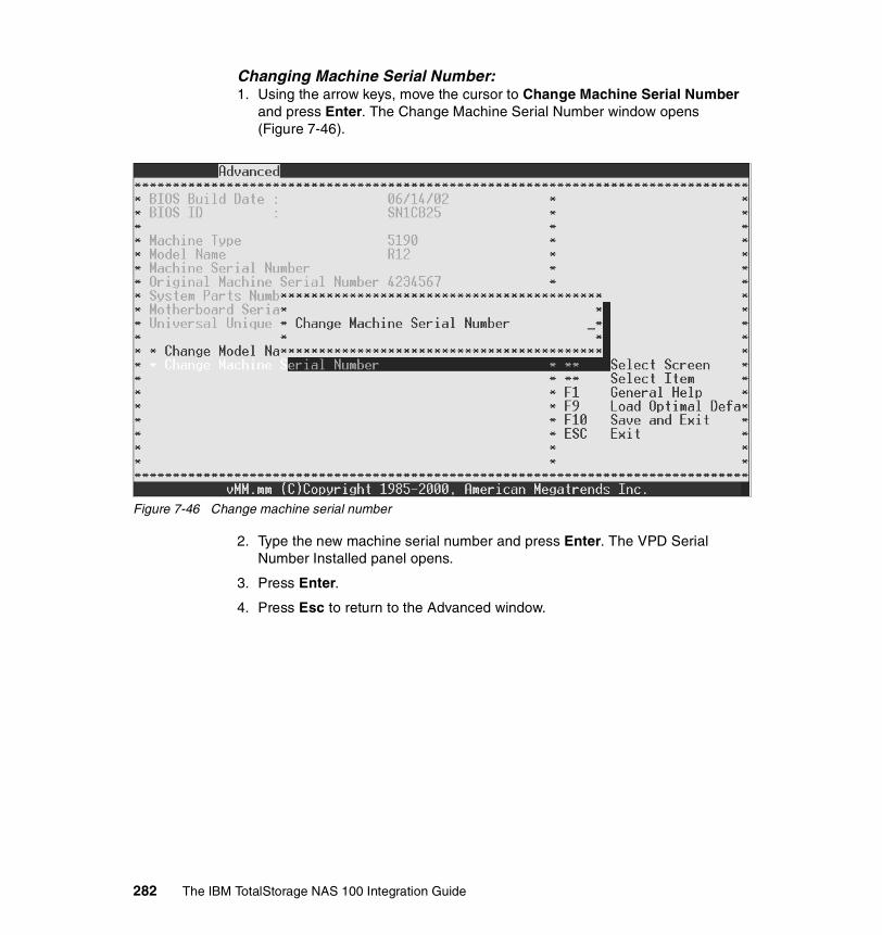
Changing Machine Serial Number:1. Using the arrow keys, move the cursor to Change Machine Serial Number
and press Enter. The Change Machine Serial Number window opens (Figure 7-46).
Figure 7-46 Change machine serial number
2. Type the new machine serial number and press Enter. The VPD Serial Number Installed panel opens.
3. Press Enter.
4. Press Esc to return to the Advanced window.
282 The IBM TotalStorage NAS 100 Integration Guide

Enabling USB supportTo get the remote control from IBM Director working on the NAS100 appliance you have to enable the USB support (Chapter 5.3.8, “Usage tips” on page 148).
1. Using the arrow keys, move the cursor to PCIPnP Configuration and press Enter. The PCIPnP Configuration window opens (Figure 7-47).
Figure 7-47 Enable USB function in PCIPnP Configuration screen
2. Move to USB Function with the arrow keys and choose Enabled.
3. Press Escape to exit the PCIPnP Configuration.
Chapter 7. Backup, restore, troubleshooting 283

ChipsetDo not change any settings in this window (Figure 7-48)!
Figure 7-48 Chipset screen
284 The IBM TotalStorage NAS 100 Integration Guide

PowerDo not change any settings in this window (Figure 7-49)!
Figure 7-49 Power screen
BootThe Boot window displays the list of bootable devices. Boot priority order is:
1. USB Floppy (if enabled)
2. USB CDROM (if enabled)
3. PXE (if enabled)
You can change the setting of the devices in this window with the following actions:
1. Using the arrow keys, move the cursor to the bootable device that you want to change and press Enter. The Options panel opens.
2. Move the cursor to either Enabled or Disabled, and press Enter.
A USB CD-ROM or floppy drive is not yet supported.
Chapter 7. Backup, restore, troubleshooting 285
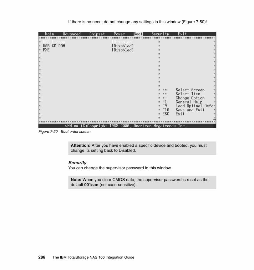
If there is no need, do not change any settings in this window (Figure 7-50)!
Figure 7-50 Boot order screen
SecurityYou can change the supervisor password in this window.
Attention: After you have enabled a specific device and booted, you must change its setting back to Disabled.
Note: When you clear CMOS data, the supervisor password is reset as the default 001san (not case-sensitive).
286 The IBM TotalStorage NAS 100 Integration Guide

1. Press Enter. The Enter New Password window opens.
2. Type the new, six-character password. The new password is displayed on the panel as ******.(Figure 7-51).
Figure 7-51 Enter new password screen
Chapter 7. Backup, restore, troubleshooting 287

3. Press Enter.
4. Retype the new password and press Enter (Figure 7-52).
Figure 7-52 Confirm password screen
288 The IBM TotalStorage NAS 100 Integration Guide

5. The Password installed panel opens (Figure 7-53).
Figure 7-53 Password installed screen
ExitThis window allows you to exit from the BIOS setup window.
Note: Although this window specifies that you press F9 and F10 for some actions, these keys are disabled. Use the arrow keys to move through each menu option.
Chapter 7. Backup, restore, troubleshooting 289

Exit Saving Changes:1. Using the arrow keys, move the cursor to Exit Saving Changes (Figure 7-54)
and press Enter. The Save configuration changes and exit now? panel opens.
Figure 7-54 Exit saving changes
2. If you want to:
– Save the changes and exit the BIOS setup, select OK and press Enter.
– Save the changes but not exit the BIOS setup, select Cancel and press Enter to return to the Exit window.
Note: When you exit the BIOS setup, the system reboots automatically.
290 The IBM TotalStorage NAS 100 Integration Guide
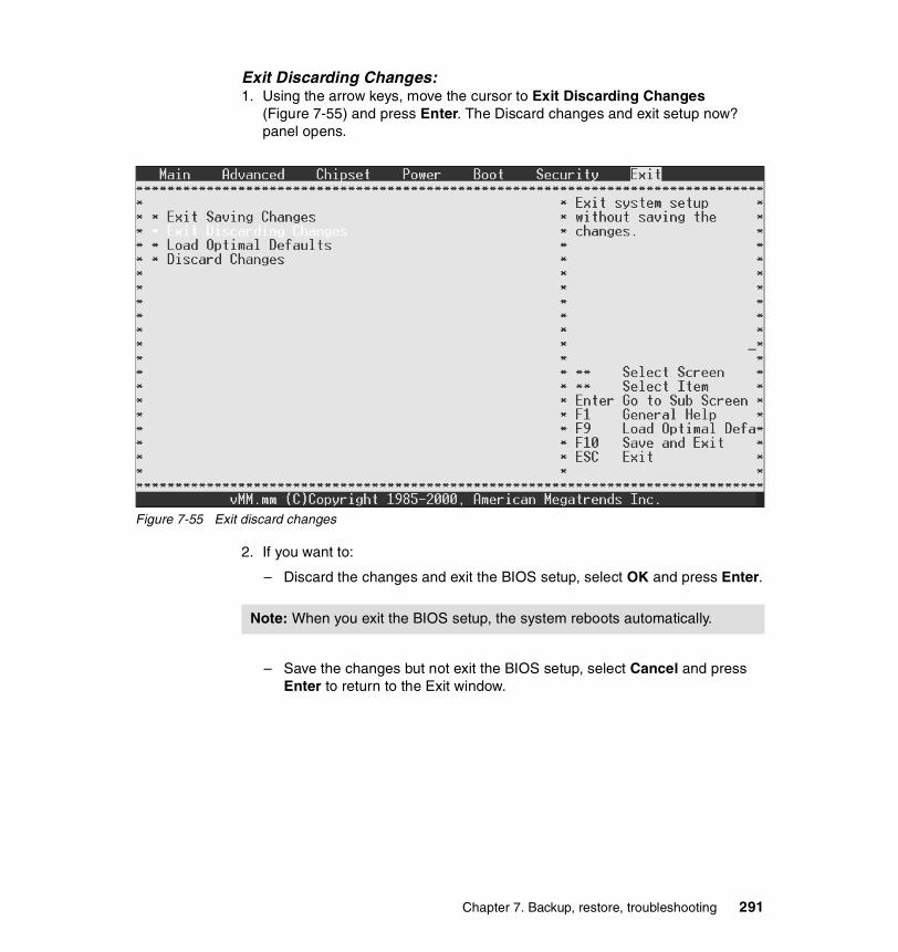
Exit Discarding Changes:1. Using the arrow keys, move the cursor to Exit Discarding Changes
(Figure 7-55) and press Enter. The Discard changes and exit setup now? panel opens.
Figure 7-55 Exit discard changes
2. If you want to:
– Discard the changes and exit the BIOS setup, select OK and press Enter.
– Save the changes but not exit the BIOS setup, select Cancel and press Enter to return to the Exit window.
Note: When you exit the BIOS setup, the system reboots automatically.
Chapter 7. Backup, restore, troubleshooting 291

Load Optimal Default:1. Using the arrow keys, move the cursor to Load Optimal Defaults
(Figure 7-56) and press Enter. The Load optimal defaults? panel opens.
Figure 7-56 Load optimal defaults
2. If you want to:
– Set all values to their defaults, select OK and press Enter to reset the values to their defaults and to return to the Exit window.
– Not set all values to their defaults, select Cancel and press Enter. The panel disappears.
292 The IBM TotalStorage NAS 100 Integration Guide

Discard Changes:1. Using the arrow keys, move the cursor to Discard Changes (Figure 7-57)
and press Enter. The Discard changes? panel opens.
Figure 7-57 Discard changes
2. If you want to:
– Discard the changes, select OK and press Enter to return to the Exit window.
– Not discard the changes, select Cancel and press Enter. The panel disappears.
7.4.4 Upgrading the BIOSYou can upgrade the BIOS by means of the serial port.
Attention: Upgrading the BIOS must be done with extreme caution. Make sure that the correct BIOS file is selected as the new BIOS when you transfer the file. If an incorrect file is loaded, you will not be able to reboot your appliance again.
Chapter 7. Backup, restore, troubleshooting 293

To upgrade the BIOS:
1. Clear the CMOS data (see “Clearing CMOS data” on page 267).
2. Connect your appliance to a PC by means of the serial port, go to:
http://www.ibm.com/storage/support
Then download a new BIOS file to the PC.
3. Follow the procedure in “Preparing to use the remote BIOS setting function” on page 268 to set up HyperTerminal.
4. Power on your appliance.
5. When the message Press <spacebar> to invoke remote BIOS flash opens, press the Spacebar.
Perform steps 5 through 8 quickly.
6. The message Begin remote BIOS flash? Y/N opens. Type Y. The message Starting remote flash opens, and then the message Update new BIOS file using Xmodem protocol.
7. When random characters appear on the screen, click Transfer from the HyperTerminal menu, and then click Send file.
8. Specify the filename field New BIOS file path in your PC, set the protocol to Xmodem, and click Send.
After you send the BIOS file, the message New BIOS received OK! Writing new BIOS to flash-Do not power DOWN or RESET! opens.
After the new BIOS is updated in the flash, the appliance beeps four times and starts rebooting automatically.
9. After the appliance has rebooted, reset the date and time. See “Making changes to the BIOS” on page 280 for the procedure.
7.5 Hard drive failure and recovery scenariosWe created four scenarios to show how to recover your system or data after a failure of a hard drive or partition. We will give instructions in detail to help you to handle such a situation.
Note: If you do not perform this step quickly enough, BIOS might proceed to the next step. If this occurs, the message Aborting remote flash opens. You will need to power off the appliance and repeat the upgrading procedure more quickly.
294 The IBM TotalStorage NAS 100 Integration Guide

7.5.1 NAS 100 boot behavior in case of a HDD failureRegarding failover of the NAS 100, If the watchdog timer is enabled (this is the default, but it can be disabled in the BIOS), and then if there is a failure of the first hard drive, the system will retry two times (total of three attempts) and if all fail, then it will try the second hard drive. A total of three attempts will be made with the second hard drive, and then the third hard drive will be used. After three more attempts, then the fourth hard drive will be used. Again, after three failures, and since there are no more hard drives to be used, it will not boot at all. Normally one of the hard drives will work.
There is a software component (a Windows service) that resets the watchdog timer. If this service does not start within five minutes of when the watchdog timer is turned on (right before entering Windows), the watchdog timer fires, the attempt is considered failed, and the system reboots and either retries with the same drive or switches to the next drive, as described above.
Please note that a hardware failure of a drive will cause it to be skipped in this process. For example, if the first two drives are removed, the NAS 100 will immediately attempt to use the third hard drive (the third and fourth hard drives contain the backup OS).
We assume that you have a backup of your system state and data for a complete recovery of the NAS 100. It will be important in some scenarios to have a backup.
7.5.2 Recovery scenariosThese are the scenarios we considered:
1. Loss of one drive (primary or backup) occurs:
– The primary and backup OS are in a RAID 1 (mirror) configuration.– The data configuration is RAID 5 (striping with parity).
2. NAS 100 does not boot from primary OS. There is a loss of primary OS (both primary drives):
– The configuration data is lost:• The configuration data must be backed up in advance.• The data (RAID 5) can be recovered.
3. Loss of both primary or both backup drives (defective) occurs:
– The configuration data and the data (RAID 5) are lost:• The configuration is maintained on the primary drives only.• The RAID 5 configuration for data now has only 2 drives.
4. No boot device is available. There is a loss of all 4 drives, primary and backup. A full system rebuild is required.
Chapter 7. Backup, restore, troubleshooting 295

Loss of one driveThe loss of a single primary OS hard drive is not disruptive and is redundant in two ways (Figure 7-58):
1. The OS is mirrored on the second drive with RAID 1 mirror.
2. The data is stored in a RAID 5 partition.
Figure 7-58 Loss of one OS hard drive
Panel lights will reflect the need to rebuild the RAID, as there is no redundancy in this state. The left light blinks green/amber 2 times a second.
1. Replace the defective drive with a new drive.
Note: The drive serial number is stored in the registry and cannot be reused in the same slot
7.81 GB Primary OS
Disk 2
7.81 GBBackup OS
Disk 3
7.81 GBBackup OS
Disk 4
7.81 GB Primary OS
Disk 1
7.81 GB Primary OS
NAS 100 Disk Organization
RAID 1 - Mirrored (D:)
RAID 5 - Raw 429GB: Usable 321 GB (E:)
RAID 1 - Mirrored (C:)
X
296 The IBM TotalStorage NAS 100 Integration Guide

2. Two options exist for rebuilding:
a. Auto rebuild:
• The drive can be inserted directly, and RAID is rebuilt.
b. Manual rebuild:
• Rebuild can be set for a certain time (for example, midnight).• The customer can initiate the rebuild process from the Web GUI by
selecting the Disks -> Admin Initiated process (Figure 7-59).
Figure 7-59 Admin initiated RAID rebuild tab
Loss of primary OS (both primary drives)Recovery scenario 2 is the loss of OS and drives 1 and 2, and prevents the NAS 100 from booting. The drives are still good and the configuration data can be preserved (Figure 7-60):
1. The OS can be recovered from the backup OS on drives 3 and 4.
2. Your data is still available in the RAID 5 partition.
3. The configuration data can be recovered if the system state data has been backed up.
Chapter 7. Backup, restore, troubleshooting 297

Figure 7-60 Loss of primary OS
The following steps have to be performed to recover your NAS 100 appliance:
1. The NAS 100 appliance will boot from the backup OS with the default DHCP/static IP address (192.168.0.1) setting.
2. Access the device by using the device name or the static IP address via terminal services session.
3. Open a DOS window and access the d:\ibm\NAS100 directory.
4. Execute the command recovery_OS.
5. The system will rebuild the OS on the first two drives and automatically reboot.
6. Login to the NAS 100 using the default static IP address (192.168.0.1).
7. Access disk management and verify the RAID is correct and other drives are valid.
8. Restore the system state data using the NT Backup Utility.
9. Verify the original users are in the configuration information.
7.81 GB Primary OS
Disk 2
7.81 GBBackup OS
Disk 3
7.81 GBBackup OS
Disk 4
7.81 GB Primary OS
Disk 1
7.81 GB Primary OS
NAS 100 Disk Organization
RAID 1 - Mirrored (D:)
RAID 5 - Raw 429GB: Usable 321 GB (E:)
RAID 1 - Mirrored (C:)X
298 The IBM TotalStorage NAS 100 Integration Guide

Loss of both primary or both backup drives (defective)This recovery scenario is similar to scenario 2, but now there are also two cylinders of the RAID 5 defective (Figure 7-61). This scenario is very unlikely, but it is covered just in case it occurs. In this case, all customer data will be lost and all configuration data will be lost.
1. The OS can be recovered from either from the primary OS or backup OS.
2. The data on the RAID 5 is lost.
Figure 7-61 Loss of both primary or both backup drives
For the system recovery, please proceed with the full system rebuild steps described next.
Full system rebuildIn the case of a complete system breakdown you have to recover the whole system. You have to follow this process in case of a failure of all four disks.
1. On both OS, inclusive, the configuration data is lost.
2. The data on the RAID 5 is lost.
7.81 GB Primary OS
Disk 2
7.81 GBBackup OS
Disk 3
7.81 GBBackup OS
Disk 4
7.81 GB Primary OS
Disk 1
7.81 GB Primary OS
NAS 100 Disk Organization
RAID 1 - Mirrored (D:)
RAID 5 - Raw 429GB: Usable 321 GB (E:)
RAID 1 - Mirrored (C:)
x x
x x
Chapter 7. Backup, restore, troubleshooting 299

To recover the whole system, the following steps must be followed precisely:
1. Copy the pre-installed BASIC system image onto a blank drive. This procedure requires a video card, display and USB keyboard.
a. Remove the cover and install the video adapter in the available PCI slot and connect the display to the adapter.
b. Connect the keyboard to the bottom USB port on the rear of the box.
c. Create a recovery hard drive (requires a Master Recovery Hard Drive).
i. Insert the Master Recovery Hard Drive in bay 1 of the NAS100 and the drive that will become the Customer’s “Recovery Hard Drive” in bay 2.
ii. Press the “Clear CMOS button (1)” on page 267 and power the box on, continuing to hold the button until a beep is heard (approximately 10 seconds).
iii. Press the F1 key to enter CMOS setup.
• Under the Advance tab, select SuperIO Configuration and disable the watchdog timer.
• Under the Advance tab, select PCIPnP Configuration and enable USB Function and Legacy USB Support.
• Save changes and exit.
d. Boot from the Master Recovery Drive.
e. Select 2. Make Another Recovery HDD Template from the menu.
f. At the Enter destination drive number[0,1,2,3] message press 1.
g. A message indicating that all data on disk will be lost and press any key to continue will appear. Press Enter.
h. At the message Are you sure you want to ZAP Fixed Disk Drive 1(Y/N)?, press Y then Enter. A message Zap of Fixed Disk Drive Complete and Press any key to continue will display. Press Enter
i. DriveImage Pro will complete the creation of the recovery hard drive.
j. The message Make another[Y,N]? will appear. Press N and the DOS prompt will appear.
k. Reboot the NAS 100 (Ctrl+Alt+Del).
l. Select 3. Copy Version Images to Another Recovery HDD (if exist) from the menu.
Note: For the full system rebuild, a Recovery Kit is required from service. This kit includes the video adapter, USB keyboard, and a Master-Master drive.
300 The IBM TotalStorage NAS 100 Integration Guide

m. When the message Enter destination drive letter[C,D,E,F]? appears, press D and the copy process will begin.
This process will take approximately 4 minutes.
n. When the message Copy to another drive[Y,N]?] is displayed, press N and you will return to the DOS prompt.
o. At the DOS prompt enter \bin\hdd0 and press <enter>.
p. Power down.
2. Create copies of the Primary and Backup OS images. This procedure requires a video card, display, and USB keyboard.
a. Replace the Master Recovery Hard Drive in bay 1 with the Customer's “Recovery Hard Drive” created in the previous step and insert the remaining 3 drives in bays 2,3,4.
b. Boot from the Recovery Hard Drive.
c. Power on the NAS 100.
d. Select 1. Start System Recovery Process from the menu and restoring of the system image will begin (approximately 12 minutes).
– Drive 1 will have the basic system image for the primary OS and drive 3 will have the basic system image for the backup OS.
e. Power down the NAS 100.
f. Remove the video adapter and keyboard.
3. Configure 4 hard drives on your NAS 100. A VGA card and keyboard are not required for this procedure. The NAS 100 will be used in headless mode (no video or keyboard).
a. Press the “Clear CMOS button (1)” on page 267 and power the box on, continuing to hold the Clear CMOS button until a beep is heard (approximately 10 seconds).
The system will boot on drive 1, the system configuration will start automatically and continue for approximately 1 hour. During this process the following will be performed:
• Intermittent drive activity LEDs will indicate build process is underway.• Setup for the OS (SID, PID, user name and company, license
agreement).• Will convert the disk from basic to dynamic.• Will create the mirrors.
b. After approximately 1 hour, watch for all LEDs on all drives to blink green/amber on a 2-second interval indicating build is complete.
Chapter 7. Backup, restore, troubleshooting 301

c. Log into the NAS 100 using either Terminal services Client or Internet Explorer Browser.
d. From a command prompt, change to “D:\IBM\NAS100” and issue the createFD command.
4. Create the RAID 5 volume and assign a drive letter and format the partition.
5. Create the RAID 5 drive and assign a drive letter and format the partition.
a. Right-click My Computer and select Manage.
b. Open the Disk Management tool
c. Right-click the Unallocated Space in Disk 0 and select Create Volume from the popup menu.
d. In the Wizard, click Next.
e. Select RAID-5 volume from the Volume Type menu and Next.
f. Select Disks 1-3 under All available dynamic disks and click Add.
g. Click Next.
h. Click Next.
i. Define a Volume label and Format type.
j. Click Next.
k. Click Finish to complete the create volume wizard.
l. The RAID 5 will begin regenerating then formatting.
m. This Process will complete in approximately 5 hours if you issue a Quick Format and 12 hours if you issue a Full Format.
n. After the regenerate/format of the RAIS 5 volume is complete, reboot the NAS 100 appliance.
6. Restore the system state data using the NT Backup Utility.
7. Verify that the original users are in the configuration information.
302 The IBM TotalStorage NAS 100 Integration Guide

Glossary
AAgent A software entity that runs on endpoints and provides management capability for other hardware or software. An example is an SNMP agent. An agent has the ability to spawn other processes.
AL See arbitrated loop.
Allocated storage The space that is allocated to volumes, but not assigned.
Allocation The entire process of obtaining a volume and unit of external storage, and setting aside space on that storage for a data set.
Arbitrated loop A Fibre Channel interconnection technology that allows up to 126 participating node ports and one participating fabric port to communicate. See also Fibre Channel Arbitrated Loop and loop topology.
Array An arrangement of related disk drive modules that have been assigned to a group.
BBandwidth A measure of the data transfer rate of a transmission channel.
Bridge Facilitates communication with LANs, SANs, and networks with dissimilar protocols.
© Copyright IBM Corp. 2003. All rights reserved.
CClient A function that requests services from a server, and makes them available to the user. A term used in an environment to identify a machine that uses the resources of the network.
Client authentication The verification of a client in secure communications where the identity of a server or browser (client) with whom you wish to communicate is discovered. A sender's authenticity is demonstrated by the digital certificate issued to the sender.
Client-server relationship Any process that provides resources to other processes on a network is a server. Any process that employs these resources is a client. A machine can run client and server processes at the same time.
Console A user interface to a server.
DDATABASE 2 (DB2) A relational database management system. DB2 Universal Database is the relational database management system that is Web-enabled with Java support.
Device driver A program that enables a computer to communicate with a specific device, for example, a disk drive.
Disk group A set of disk drives that have been configured into one or more logical unit numbers. This term is used with RAID devices.
303

EEnterprise network A geographically dispersed network under the backing of one organization.
Enterprise Storage Server Provides an intelligent disk storage subsystem for systems across the enterprise.
Event In the Tivoli environment, any significant change in the state of a system resource, network resource, or network application. An event can be generated for a problem, for the resolution of a problem, or for the successful completion of a task. Examples of events are: the normal starting and s ping of a process, the abnormal termination of a process, and the malfunctioning of a server.
FFabric The Fibre Channel employs a fabric to connect devices. A fabric can be as simple as a single cable connecting two devices. The term is often used to describe a more complex network utilizing hubs, switches, and gateways.
FC See Fibre Channel.
FCS See Fibre Channel standard.
Fiber optic The medium and the technology associated with the transmission of information along a glass or plastic wire or fiber.
Fibre Channel A technology for transmitting data between computer devices at a data rate of up to 1 Gb. It is especially suited for connecting computer servers to shared storage devices and for interconnecting storage controllers and drives.
Fibre Channel Arbitrated Loop A reference to the FC-AL standard, a shared gigabit media for up to 127 nodes, one of which can be attached to a switch fabric. See also arbitrated loop and loop topology. Refer to American National Standards Institute (ANSI) X3T11/93-275.
Fibre Channel standard An ANSI standard for a computer peripheral interface. The I/O interface defines a protocol for communication over a serial interface that configures attached units to a communication fabric. Refer to ANSI X3.230-199x.
File system An individual file system on a host. This is the smallest unit that can monitor and extend. Policy values defined at this level override those that might be defined at higher levels.
GGateway In the SAN environment, a gateway connects two or more different remote SANs with each other. A gateway can also be a server on which a gateway component runs.
HHardware zoning Hardware zoning is based on physical ports. The members of a zone are physical ports on the fabric switch. It can be implemented in the following configurations: one to one, one to many, and many to many.
HBA See host bus adapter.
304 The IBM TotalStorage NAS 100 Integration Guide

Host Any system that has at least one internet address associated with it. A host with multiple network interfaces can have multiple internet addresses associated with it. This is also referred to as a server.
Host bus adapter (HBA) A Fibre Channel HBA connection that allows a workstation to attach to the SAN network.
Hub A Fibre Channel device that connects up to 126 nodes into a logical loop. All connected nodes share the bandwidth of this one logical loop. Hubs automatically recognize an active node and insert the node into the loop. A node that fails or is powered off is automatically removed from the loop.
IP Internet protocol.
JJava A programming language that enables application developers to create object-oriented programs that are very secure, portable across different machine and operating system platforms, and dynamic enough to allow expandability.
Java runtime environment (JRE) The underlying, invisible system on your computer that runs applets the browser passes to it.
Java Virtual Machine (JVM) The execution environment within which Java programs run. The Java virtual machine is described by the Java Machine Specification which is published by Sun Microsystems. Because the Tivoli Kernel Services is based on Java, nearly all ORB and component functions execute in a Java virtual machine.
JBOD Just a Bunch Of Disks.
JRE See Java runtime environment.
JVM See Java Virtual Machine.
LLogical unit number (LUN) The LUNs are provided by the storage devices attached to the SAN. This number provides you with a volume identifier that is unique among all storage servers. The LUN is synonymous with a physical disk drive or a SCSI device. For disk subsystems such as the IBM Enterprise Storage Server, a LUN is a logical disk drive. This is a unit of storage on the SAN which is available for assignment or unassignment to a host server.
Loop topology In a loop topology, the available bandwidth is shared with all the nodes connected to the loop. If a node fails or is not powered on, the loop is out of operation. This can be corrected using a hub. A hub opens the loop when a new node is connected and closes it when a node disconnects. See also Fibre Channel Arbitrated Loop and arbitrated loop.
LUN See logical unit number.
LUN assignment criteria The combination of a set of LUN types, a minimum size, and a maximum size used for selecting a LUN for automatic assignment.
LUN masking This allows or blocks access to the storage devices on the SAN. Intelligent disk subsystems like the IBM Enterprise Storage Server provide this kind of masking.
MManaged object A managed resource.
Glossary 305

Managed resource A physical element to be managed.
Management Information Base (MIB) A logical database residing in the managed system which defines a set of MIB objects. A MIB is considered a logical database because actual data is not stored in it, but rather provides a view of the data that can be accessed on a managed system.
MIB See Management Information Base.
MIB object A MIB object is a unit of managed information that specifically describes an aspect of a system. Examples are CPU utilization, software name, hardware type, and so on. A collection of related MIB objects is defined as a MIB.
NNetwork topology A physical arrangement of nodes and interconnecting communications links in networks based on application requirements and geographical distribution of users.
N_Port node port A Fibre Channel-defined hardware entity at the end of a link which provides the mechanisms necessary to transport information units to or from another node.
NL_Port node loop port A node port that supports arbitrated loop devices.
OOpen system A system whose characteristics comply with standards made available throughout the industry, and therefore can be connected to other systems that comply with the same standards.
PPoint-to-point topology It consists of a single connection between two nodes. All the bandwidth is dedicated for these two nodes.
Port An end point for communication between applications, generally referring to a logical connection. A port provides queues for sending and receiving data. Each port has a port number for identification. When the port number is combined with an Internet address, it is called a socket address.
Port zoning In Fibre Channel environments, port zoning is the grouping together of multiple ports to form a virtual private storage network. Ports that are members of a group or zone can communicate with each other but are isolated from ports in other zones. See also LUN masking and subsystem masking.
Protocol The set of rules governing the operation of functional units of a communication system if communication is to take place. Protocols can determine low-level details of machine-to-machine interfaces, such as the order in which bits from a byte are sent. They can also determine high-level exchanges between application programs, such as file transfer.
306 The IBM TotalStorage NAS 100 Integration Guide

RRAID Redundant array of inexpensive or independent disks. A method of configuring multiple disk drives in a storage subsystem for high availability and high performance.
SSAN See storage area network.
SAN agent A software program that communicates with the manager and controls the subagents. This component is largely platform independent. See also subagent.
SCSI Small Computer System Interface. An ANSI standard for a logical interface to computer peripherals and for a computer peripheral interface. The interface utilizes a SCSI logical protocol over an I/O interface that configures attached targets and initiators in a multi-drop bus topology.
Server A program running on a mainframe, workstation, or file server that provides shared services. This is also referred to as a host.
Shared storage Storage within a storage facility that is configured such that multiple homogeneous or divergent hosts can concurrently access the storage. The storage has a uniform appearance to all hosts. The host programs that access the storage must have a common model for the information on a storage device. You need to design the programs to handle the effects of concurrent access.
Simple Network Management Protocol (SNMP) A protocol designed to give a user the capability to remotely manage a computer network by polling and setting terminal values and monitoring network events.
SNMP See Simple Network Management Protocol.
SNMP agent An implementation of a network management application which is resident on a managed system. Each node that is to be monitored or managed by an SNMP manager in a TCP/IP network, must have an SNMP agent resident. The agent receives requests to either retrieve or modify management information by referencing MIB objects. MIB objects are referenced by the agent whenever a valid request from an SNMP manager is received.
SNMP manager A managing system that executes a managing application or suite of applications. These applications depend on MIB objects for information that resides on the managed system.
SNMP trap A message that is originated by an agent application to alert a managing application of the occurrence of an event.
Software zoning Is implemented within the Simple Name Server (SNS) running inside the fabric switch. When using software zoning, the members of the zone can be defined with: node WWN, port WWN, or physical port number. Usually the zoning software also allows you to create symbolic names for the zone members and for the zones themselves.
SQL Structured Query Language.
Storage administrator A person in the data processing center who is responsible for defining, implementing, and maintaining storage management policies.
Storage area network (SAN) A managed, high-speed network that enables any-to-any interconnection of heterogeneous servers and storage systems.
Glossary 307

Subagent A software component of SAN products which provides the actual remote query and control function, such as gathering host information and communicating with other components. This component is platform dependent. See also SAN agent.
Subsystem masking The support provided by intelligent disk storage subsystems like the Enterprise Storage Server. See also LUN masking and port zoning.
Switch A component with multiple entry and exit points or ports that provide dynamic connection between any two of these points.
Switch topology A switch allows multiple concurrent connections between nodes. There can be two types of switches, circuit switches and frame switches. Circuit switches establish a dedicated connection between two nodes. Frame switches route frames between nodes and establish the connection only when needed. A switch can handle all protocols.
TTCP See Transmission Control Protocol.
TCP/IP Transmission Control Protocol/Internet Protocol.
Topology An interconnection scheme that allows multiple Fibre Channel ports to communicate. For example, point-to-point, arbitrated loop, and switched fabric are all Fibre Channel topologies.
Transmission Control Protocol (TCP) A reliable, full duplex, connection-oriented, end-to-end transport protocol running on of IP.
WWAN Wide Area Network.
ZZoning In Fibre Channel environments, zoning allows for finer segmentation of the switched fabric. Zoning can be used to instigate a barrier between different environments. Ports that are members of a zone can communicate with each other but are isolated from ports in other zones. Zoning can be implemented in two ways: hardware zoning and software zoning.
Other glossaries:
For more information on IBM terminology, see the IBM Storage Glossary of Terms at:
http://www.storage.ibm.com/glossary.htm
For more information on Tivoli terminology, see the Tivoli Glossary at:
http://www.tivoli.com/support/documents/glossary/termsm03.htm
308 The IBM TotalStorage NAS 100 Integration Guide

Glossary 309

310 The IBM TotalStorage NAS 100 Integration Guide

acronyms
ABI Application Binary Interface
ACE Access Control Entries
ACL Access Control List
AD Microsoft Active Directory
ADSM ADSTAR Distributed Storage Manager
AFS Andrew File System
AIX Advanced Interactive eXecutive
ANSI American National Standards Institute
APA All Points Addressable
API Application Programming Interface
APPC Advanced Program-to-Program Communication
APPN Advanced Peer-to-Peer Networking
ARC Advanced RISC Computer
ARPA Advanced Research Projects Agency
ASCII American National Standard Code for Information Interchange
ATE Asynchronous Terminal Emulation
ATM Asynchronous Transfer Mode
AVI Audio Video Interleaved
BDC Backup Domain Controller
Abbreviations and
© Copyright IBM Corp. 2003. All rights reserved.
BIND Berkeley Internet Name Domain
BNU Basic Network Utilities
BOS Base Operating System
BRI Basic Rate Interface
BSD Berkeley Software Distribution
BSOD Blue Screen of Death
BUMP Bring-Up Microprocessor
CA Certification Authorities
CAL Client Access License
C-SPOC Cluster single point of control
CDE Common Desktop Environment
CDMF Commercial Data Masking Facility
CDS Cell Directory Service
CERT Computer Emergency Response Team
CGI Common Gateway Interface
CHAP Challenge Handshake Authentication
CIDR Classless InterDomain Routing
CIFS Common Internet File System
CMA Concert Multi-threaded Architecture
CO Central Office
COPS Computer Oracle and Password System
311

CPI-C Common Programming Interface for Communications
CPU Central Processing Unit
CSNW Client Service for NetWare
CSR Client/server Runtime
DAC Discretionary Access Controls
DARPA Defense Advanced Research Projects Agency
DASD Direct Access Storage Device
DBM Database Management
DCE Distributed Computing Environment
DCOM Distributed Component Object Model
DDE Dynamic Data Exchange
DDNS Dynamic Domain Name System
DEN Directory Enabled Network
DES Data Encryption Standard
DFS Distributed File System
DHCP Dynamic Host Configuration Protocol
DLC Data Link Control
DLL Dynamic Load Library
DS Differentiated Service
DSA Directory Service Agent
DSE Directory Specific Entry
DNS Domain Name System
DTS Distributed Time Service
EFS Encrypting File Systems
EGID Effective Group Identifier
EISA Extended Industry Standard Architecture
EMS Event Management Services
EPROM Erasable Programmable Read-Only Memory
ERD Emergency Repair Disk
ERP Enterprise Resources Planning
ERRM Event Response Resource Manager
ESCON Enterprise System Connection
ESP Encapsulating Security Payload
ESS Enterprise Storage Server
EUID Effective User Identifier
FAT File Allocation Table
FC Fibre Channel
FDDI Fiber Distributed Data Interface
FDPR Feedback Directed Program Restructure
FEC Fast EtherChannel technology
FIFO First In/First Out
FIRST Forum of Incident Response and Security
FQDN Fully Qualified Domain Name
FSF File Storage Facility
FTP File Transfer Protocol
FtDisk Fault-Tolerant Disk
GC Global Catalog
GDA Global Directory Agent
GDI Graphical Device Interface
312 The IBM TotalStorage NAS 100 Integration Guide

GDS Global Directory Service
GID Group Identifier
GL Graphics Library
GSNW Gateway Service for NetWare
GUI Graphical User Interface
HA High Availability
HACMP High Availability Cluster Multiprocessing
HAL Hardware Abstraction Layer
HBA Host Bus Adapter
HCL Hardware Compatibility List
HSM Hierarchical Storage Management
HTTP Hypertext Transfer Protocol
IBM International Business Machines Corporation
ICCM Inter-Client Conventions Manual
IDE Integrated Drive Electronics
IDL Interface Definition Language
IDS Intelligent Disk Subsystem
IEEE Institute of Electrical and Electronic Engineers
IETF Internet Engineering Task Force
IGMP Internet Group Management Protocol
IIS Internet Information Server
IKE Internet Key Exchange
IMAP Internet Message Access Protocol
I/O Input/Output
IP Internet Protocol
IPC Interprocess Communication
IPL Initial Program Load
IPsec Internet Protocol Security
IPX Internetwork Packet eXchange
ISA Industry Standard Architecture
iSCSI SCSI over IP
ISDN Integrated Services Digital Network
ISNO Interface-specific Network Options
ISO International Standards Organization
ISS Interactive Session Support
ISV Independent Software Vendor
ITSEC Initial Technology Security Evaluation
ITSO International Technical Support Organization
ITU International Telecommunications Union
IXC Inter Exchange Carrier
JBOD Just a Bunch of Disks
JFS Journaled File System
JIT Just-In-Time
L2F Layer 2 Forwarding
L2TP Layer 2 Tunneling Protocol
LAN Local Area Network
LCN Logical Cluster Number
Abbreviations and acronyms 313

LDAP Lightweight Directory Access Protocol
LFS Log File Service (Windows NT)
LFS Logical File System (AIX)
LFT Low Function Terminal
JNDI Java Naming and Directory Interface
LOS Layered Operating System
LP Logical Partition
LPC Local Procedure Call
LPD Line Printer Daemon
LPP Licensed Program Product
LRU Least Recently Used
LSA Local Security Authority
LTG Local Transfer Group
LUID Login User Identifier
LUN Logical Unit Number
LVCB Logical Volume Control Block
LVDD Logical Volume Device Driver
LVM Logical Volume Manager
MBR Master Boot Record
MCA Micro Channel Architecture
MDC Meta Data Controller
MFT Master File Table
MIPS Million Instructions Per Second
MMC Microsoft Management Console
MOCL Managed Object Class Library
MPTN Multi-protocol Transport Network
MS-DOS Microsoft Disk Operating System
MSCS Microsoft Cluster Server
MSS Maximum Segment Size
MSS Modular Storage Server
MWC Mirror Write Consistency
NAS Network Attached Storage
NBC Network Buffer Cache
NBF NetBEUI Frame
NBPI Number of Bytes per I-node
NCP NetWare Core Protocol
NCS Network Computing System
NCSC National Computer Security Center
NDIS Network Device Interface Specification
NDMP Network Data Management Protocol
NDS NetWare Directory Service
NETID Network Identifier
NFS Network File System
NIM Network Installation Management
NIS Network Information System
NIST National Institute of Standards and Technology
NLS National Language Support
NNS Novell Network Services
314 The IBM TotalStorage NAS 100 Integration Guide

NSAPI Netscape Commerce Server's Application
NTFS NT File System
NTLDR NT Loader
NTLM NT LAN Manager
NTP Network Time Protocol
NTVDM NT Virtual DOS Machine
NVRAM Non-Volatile Random Access Memory
NetBEUI NetBIOS Extended User Interface
NetDDE Network Dynamic Data Exchange
OCS On-Chip Sequencer
ODBC Open Database Connectivity
ODM Object Data Manager
OLTP OnLine Transaction Processing
OMG Object Management Group
ONC Open Network Computing
OS Operating System
OSF Open Software Foundation
OU Organizational Unit
PAL Platform Abstract Layer
PAM Pluggable Authentication Module
PAP Password Authentication Protocol
PBX Private Branch Exchange
PCI Peripheral Component Interconnect
PCMCIA Personal Computer Memory Card International Association
PDC Primary Domain Controller
PDF Portable Document Format
PDT Performance Diagnostic Tool
PEX PHIGS Extension to X
PFS Physical File System
PHB Per Hop Behavior
PHIGS Programmer's Hierarchical Interactive Graphics System
PID Process Identification Number
PIN Personal Identification Number
PMTU Path Maximum Transfer Unit
POP Post Office Protocol
POSIX Portable Operating System Interface for Computer Environment
POST Power-On Self Test
PP Physical Partition
PPP Point-to-Point Protocol
PPTP Point-to-Point Tunneling Protocol
PReP PowerPC Reference Platform
PSM Persistent Storage Manager
PSN Program Sector Number
PSSP Parallel System Support Program
PV Physical Volume
Abbreviations and acronyms 315

PVID Physical Volume Identifier
QoS Quality of Service
RACF Resource Access Control Facility
RAID Redundant Array of Independent Disks
RAS Remote Access Service
RDBMS Relational Database Management System
RFC Request for Comments
RGID Real Group Identifier
RISC Reduced Instruction Set Computer
RMC Resource Monitoring and Control
RMSS Reduced-Memory System Simulator
ROLTP Relative OnLine Transaction Processing
ROS Read-Only Storage
RPC Remote Procedure Call
RRIP Rock Ridge Internet Protocol
RSCT Reliable Scalable Cluster Technology
RSM Removable Storage Management
RSVP Resource Reservation Protocol
SACK Selective Acknowledgments
SAK Secure Attention Key
SAM Security Account Manager
SAN Storage Area Network
SASL Simple Authentication and Security Layer
SCSI Small Computer System Interface
SDK Software Developer's Kit
SFG Shared Folders Gateway
SFU Services for UNIX
SID Security Identifier
SLIP Serial Line Internet Protocol
SMB Server Message Block
SMIT System Management Interface Tool
SMP Symmetric Multiprocessor
SMS Systems Management Server
SNA Systems Network Architecture
SNAPI SNA Interactive Transaction Program
SNMP Simple Network Management Protocol
SP System Parallel
SPX Sequenced Packet eXchange
SQL Structured Query Language
SRM Security Reference Monitor
SSA Serial Storage Architecture
SSL Secure Sockets Layer
SUSP System Use Sharing Protocol
SVC Serviceability
TAPI Telephone Application Program Interface
TCB Trusted Computing Base
316 The IBM TotalStorage NAS 100 Integration Guide
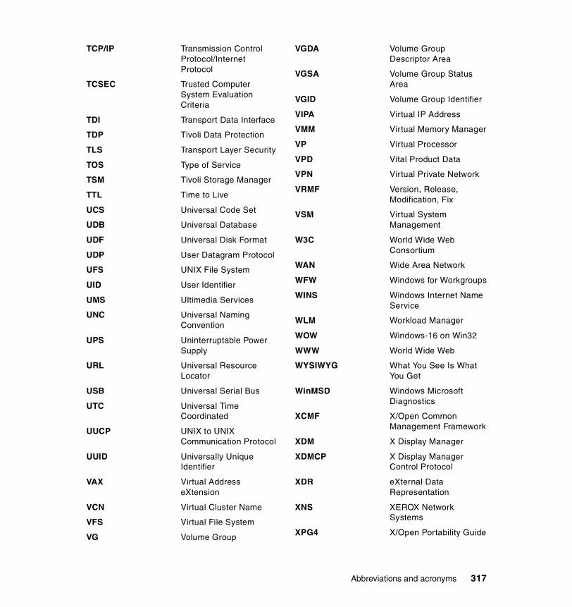
TCP/IP Transmission Control Protocol/Internet Protocol
TCSEC Trusted Computer System Evaluation Criteria
TDI Transport Data Interface
TDP Tivoli Data Protection
TLS Transport Layer Security
TOS Type of Service
TSM Tivoli Storage Manager
TTL Time to Live
UCS Universal Code Set
UDB Universal Database
UDF Universal Disk Format
UDP User Datagram Protocol
UFS UNIX File System
UID User Identifier
UMS Ultimedia Services
UNC Universal Naming Convention
UPS Uninterruptable Power Supply
URL Universal Resource Locator
USB Universal Serial Bus
UTC Universal Time Coordinated
UUCP UNIX to UNIX Communication Protocol
UUID Universally Unique Identifier
VAX Virtual Address eXtension
VCN Virtual Cluster Name
VFS Virtual File System
VG Volume Group
VGDA Volume Group Descriptor Area
VGSA Volume Group Status Area
VGID Volume Group Identifier
VIPA Virtual IP Address
VMM Virtual Memory Manager
VP Virtual Processor
VPD Vital Product Data
VPN Virtual Private Network
VRMF Version, Release, Modification, Fix
VSM Virtual System Management
W3C World Wide Web Consortium
WAN Wide Area Network
WFW Windows for Workgroups
WINS Windows Internet Name Service
WLM Workload Manager
WOW Windows-16 on Win32
WWW World Wide Web
WYSIWYG What You See Is What You Get
WinMSD Windows Microsoft Diagnostics
XCMF X/Open Common Management Framework
XDM X Display Manager
XDMCP X Display Manager Control Protocol
XDR eXternal Data Representation
XNS XEROX Network Systems
XPG4 X/Open Portability Guide
Abbreviations and acronyms 317

318 The IBM TotalStorage NAS 100 Integration Guide

Related publications
The publications listed in this section are considered particularly suitable for a more detailed discussion of the topics covered in this redbook.
IBM RedbooksFor information on ordering these publications, see “How to get IBM Redbooks” on page 322.
� IBM TotalStorage NAS Integration Guide, SG24-6505
� Implementing the IBM TotalStorage NAS 300G, High Speed Cross Platform Storage and Tivoli SANergy!, SG24-6278
� IBM TotalStorage NAS Backup and Recovery Solutions, SG24-6831-00
� Managing IBM TotalStorage NAS with IBM Director, SG24-6830-00
� IP Storage Networking: NAS and iSCSI Solutions, SG24-6240
� Implementing IBM Director Management Solutions, SG24-6188.
� A Practical Guide to Tivoli SANergy, SG24-6146
� Tivoli SANergy Administrator’s Guide, GC26-7389
� Tivoli Storage Management Concepts, SG24-4877
� Getting Started with Tivoli Storage Manager: Implementation Guide, SG24-5416
� Using Tivoli Storage Manager in a SAN Environment, SG24-6132
� Tivoli Storage Manager Version 4.2: Technical Guide, SG24-6277
� Red Hat Linux Integration Guide for IBM eServer xSeries and Netfinity, SG24-5853
� AIX 5L and Windows 2000: Side by Side, SG24-4784
� Migrating IBM Netfinity Servers to Microsoft Windows 2000, SG24-5854
� Using TSM in a Clustered NT Environment, SG24-5742
� ESS Solutions for Open Systems Storage: Compaq Alpha Server, HP and SUN, SG24-6119
� Backing Up DB2 Using Tivoli Storage Manager, SG24-6247-00
© Copyright IBM Corp. 2003. All rights reserved. 319

Other resourcesThese publications are also relevant as further information sources:
� Larry Peterson and Bruce Davie, Computer Networks - A Systems Approach, Morgan Kaufmann Publishers, 1996, ISBN 1558603689
� A. S. Tanenbaum, Computer Networks, Prentice Hall, 1996, ISBN 0133499456
� M. Schwartz, Telecommunication Networks: Protocols, Modeling and Analysis, Addison-Wesley, 1986, ISBN 020116423X
� Matt Welsh, Mathias Kalle Dalheimer, and Lar Kaufman, Running Linux (3rd Edition), O’Reilly, 1999, ISBN 156592469X
� Scott M. Ballew, Managing IP Networks with CISCO Routers, O’Reilly, 1997, ISBN 1565923200
� Ellen Siever, et al., Linux in a Nutshell (3rd Edition), O’Reilly, 2000, ISBN 0596000251
� Andreas Siegert, The AIX Survival Guide, Addison-Wesley, 1996, ISBN 0201593882
� William Boswell, Inside Windows 2000 Server, New Riders, 1999, ISBN 1562059297
� Paul Albitz and Cricket Liu, DNS and BIND (4th Edition), O’Reilly, 2001, ISBN 0596001584
� Gary L. Olsen and Ty Loren Carlson, Windows 2000 Active Directory Design and Deployment, New Riders, 2000, ISBN1578702429
� Microsoft Windows 2000 Professional Resource Kit, Microsoft Press, 2000, ISBN 1572318082
� D. Libertone, Windows 2000 Cluster Server Guidebook, Prentice Hall, 2000, ISBN 0130284696
� Microsoft Services for UNIX version 2 white paper, found at:
http://www.microsoft.com/WINDOWS2000/sfu/sfu2wp.asp
� C. J. Date, An Introduction to Database Systems (7th Edition), Addison-Wesley, 1999, ISBN 0201385902
� George Baklarz and Bill Wong, DB2 Universal Database V7.1, Prentice Hall, 2001, ISBN 0130913669
320 The IBM TotalStorage NAS 100 Integration Guide320 The IBM TotalStorage NAS 100 Integration Guide

Referenced Web sitesThese Web sites are also relevant as further information sources:
� IBM Storagehttp://www.storage.ibm.com/
� IBM TotalStoragehttp://www.storage.ibm.com/ssg
� IBM NAShttp://www.storage.ibm.com/snetwork/nas/index.html
� IBM NAS reference informationhttp://www.storage.ibm.com/snetwork/nas/library.html
� IBM TotalStorage NAS 100http://www.storage.ibm.com/snetwork/nas/100/index.html
� IBM TotalStorage NAS 200http://www.storage.ibm.com/snetwork/nas/200/index.html
� IBM TotalStorage NAS 300http://www.storage.ibm.com/snetwork/nas/300/index.html
� IBM TotalStorage NAS 300Ghttp://www.storage.ibm.com/snetwork/nas/300g_product_page.htm
� Microsoft Technical Libraryhttp://www.microsoft.com/windows2000/techinfo/default.asp
� Microsoft Services for UNIXhttp://www.microsoft.com/WINDOWS2000/sfu/default.asp
� Tivolihttp://www.tivoli.com/
� Tivoli Sanergy Supporthttp://www.tivoli.com/support/sanergy
� Storage Networking Industry Association http://www.snia.org/
� Sysinternals Microsoft Toolshttp://www.sysinternals.com/
� Linux Documentationhttp://www.linuxdoc.org/
� Linux Kernel Resourcehttp://www.kernel.org/
� Red Hat Linuxhttp://www.redhat.com/
Related publications 321

� SUSE Linuxhttp://www.suse.com/index_us.html
How to get IBM RedbooksSearch for additional IBM Redbooks or Redpieces, view, download, or order hardcopy from the Redbooks Web site:
ibm.com/redbooks
Also download additional materials (code samples or diskette/CD-ROM images) from this IBM Redbooks site.
Redpieces are IBM Redbooks in progress; not all Redpieces become IBM Redbooks, and sometimes just a few chapters will be published this way. The intent is to get the information out more quickly than the formal publishing process allows.
IBM Redbooks collectionsIBM Redbooks are also available on CD-ROMs. Click the CD-ROMs button on the IBM Redbooks Web site for information about all the CD-ROMs offered, as well as updates and formats.
322 The IBM TotalStorage NAS 100 Integration Guide322 The IBM TotalStorage NAS 100 Integration Guide

Index
Numerics802.3ad 97
AActive Directory 64
joining 65Advanced Appliance Configuration Utility 28advanced configuration 69AIX clients 222alert on LAN 28Apple File Protocol 25, 66Application layer 9ATA 31ATA controller 60
Bbackup 231
archival 233native 232point-in-time 232
BIOS 267change 280
Block I/O 12, 15book structure 2boot behavior 295bootchg command 266Broadcom NetXtreme 99bus topology 3
CCapacity Manager 110, 139centralized management 158character sets 181character translation 220CIFS 10–11, 18, 25, 66, 222Clear CMOS button 267CMOS 267Common Internet File System 10–11concept
main 1configCMOS command 266Configuration 46
© Copyright IBM Corp. 2003. All rights reserved.
connectionless service 6connectivity 17credentials_file 224crfs command 222cross platform share 202
without a Domain Controller 202Cross Platform Storage 171cross platform storage 171
Ddata integrity 19datagram 7DHCP Server 28, 36, 42, 99Diagnostics 30Disaster Recovery 92Discovering NAS systems 111disk quota 71Disk subsystems management 62DNS Server 28dsm.opt 241
EError messages 258Ethernet adapter Teaming
Trunking 97Ethernet adapter teaming 97
97802.3ad 97Create Team 101Generic link aggregation 98link aggregation 97Load Balance/Virtual Lan 101load balancing 97Load Balancing configuration 98Overview 97Trunking 98
Ethernet port status LEDs 262
FFailure Analysis 30file access 178File I/O 12, 15
323

file servers 13File sharing
permissions 175file sharing 18filesystem
Apple File Protocol 25, 66CIFS 25, 66Netware 25, 66NFS 25, 56, 66
filesystems 10Fixes 193fstab 220–221, 224FTP 25, 66Full system rebuild 299
GGateway for NFS 184, 205
authentication 205configuration 216mapping from Windows clients 218
Generic link aggregation 98Gigabit 97group file 193
HHard disk drive LEDs 261Hard drive failure 294headless appliance 36host 228HP-UX clients 220HTTP 25, 66
II/O 10IAACU 37, 40, 42–43
Assigning IP Address 43create group 43group type 44main screen 43name policy 45Reprovisioning 45
IBM Advanced Appliance Configuration Utility 28, 37, 42IBM Director 27, 108
action management 117Actions 117analyze graph 144
Capacity Manager 110, 139Cluster Systems Management 110console 112description 108detailed report 139discover systems 113Discovering NAS systems 111Event action 125Event action plan 126Event Filters 117Event filters 124Event Log 122event management 117execute tasks 114Extensions to IBM Director 151Forecast 145Generating a Report 142grouping systems 117IBM NAS Appliances 157Importing Event Action Plans 131interoperability facts 111Management Processor Assistant 109management standards 111Monitor Activator 141Performance Analysis 146Performance Analysis report 147preload 111Rack Manager 110, 133Report Generator 142Report Viewer 143Resource Monitor 120resource monitor 118selective disvovering 113Software Rejuvenation 110statistics view 136system attributes 115System Availability 110, 135Threshold Settings 120threshold settings 119use 111using system threshold 117
IBM Director Agent 26–27, 109IBM Director Console 109IBM Director Server 108IBM Director Server Extensions 109IBM NAS ADMIN.MSC 197IBM NAS Extensions to IBM Director 151IBM TotalStorage NAS
access with Internet Explorer 52
324 The IBM TotalStorage NAS 100 Integration Guide

management 109Terminal Services 48
IBM TotalStorage NAS 100 29advanced configuration 69advantages 29Basic configuration 55highlights 31implementation 35Java Swing 47storage configuration 60XML support 47
IBM TotalStorage Release 2.5at a glance 33
IBMSNAP 26, 234and PSM creating an image 235batch file 250Removable Disk 239Scheduled NT Backup 240Scheduled TSM Backup 257with NTBackup 234with TSM 241
IETF 20–21include-exclude list 248interface 46Internet Engineering Task Force 20–21Internet Explorer 52Internet Protocol 6IP 6IP address 7, 36, 39, 46–47IP network 23IP packet 7
LLAN 3LAN bandwidth 19LEDs 259Light Path Diagnostics 30Link aggregation 97link aggregation 97Linux 222Linux clients 220lmhosts 228load balancing 97Local Area Networks 3Loss of primary OS 297
MMaintanance Tools 266
management 158Management Console 46Management Processor Assistant 109Map Network Drive 178MDM 158
and NAS 100 159centralized management 158Control Devices 167Controller installation 161Create Sets 164functions 162Query, configure and distribute software 168Run Jobs 162
MicrosoftInternet Explorer 52
Microsoft JET 109Microsoft Management Console 46Microsoft Multiple Device Manager. see MDMMicrosoft Services for UNIX 26, 40, 62–63, 183, 203
additional functions SFU 2.3 181anonymous access 181character sets 181character translation 220configuration 193Configuring 197Fixes 193Gateway for NFS 184, 205, 216Get the Password and Group files 193HotFixes 193NFS client groups 204NFS user mapping 197, 203primary group 192Server for NFS 203Server for PCNFS 205shared storage 211User Name Mapping 207users and groups 193
MMC 46mount 223MSCS
Cluster Systems Management 110
NNAS 13, 23
advanced configuration 69appliances 14benefits 16, 24
Index 325

enhanced backup 18features 24File I/O 15included software 24interoperability features 24manageability 18Network Attached Storage 13optional software 25preloaded software 25Remote administration 25Setup Navigator 54software configuration 25systems management 107TCP/IP ports 46Using a keyboard, mouse, and monitor 36web manager 47Windows Powered OS 25
NAS Backup Assistant 26, 241NAS Setup Navigator 54
configure NAS appliance 56NFS 55using for NAS 100 setup 55
net share command 177net use command 179Netware 25, 66network appliances 14Network Attached Storage 1, 13, 23network file system protocols 10Network layer 6NFS 10–11, 18, 25, 40, 56, 66–67, 180, 184
client 180client groups 204clients 213Gateway 184groups 213share permissions 182, 211sharing 211user mapping 197, 203
NFS file sharinghost definition 182sharing 180
NFS Gateway 184, 205NFS Server 184, 203NFS share
access control settings 216add clients and groups 213Implicit Permission 215permissions 212
nfsshare command 183
NISIntegration 63master 63slave 63
NTBackup 234
OOpen Systems Interconnection 5Operator panel LEDs 259oplocks 12OSI 5
compared to TCP/IP 5model 5
Ppacket 7passwd file 193password
NAS 100 default password 38payload 7PCNFS 205, 207
user name mapping 207PCNFS Server 205performance 19Performance Analysis 146Persistent Storage Manager see PSMPersistent Storage Manager. see PSMPersistent True Image 76Predictive Failure Analysis 30Presentation layer 9protocol stack 9protocol suite 9Protocols 10protocols 10PSM 26, 233
and IBMSNAP creating an image 235automated TSM backup 253backup software solutions 233batch file 250Cache full warning threshold 84Cache size 84Configuring 82copy-on-write 77create boot disk 96Creating a Scheduled Image 88Creating an image 85Creating an Immediate image 85Creating images 79
326 The IBM TotalStorage NAS 100 Integration Guide

definition 75disaster recovery 92disaster recovery properties 94File Systems Access 90first image 78fixboot.bat 96how it works 76IBMSNAP 234image directory 83main screen 81Maximum images 82NAS Volume 77Performance impact 78Persistent True Image 76process priority 78Quiescent period 82Quiescent time-out 83Read Performance 79Reading True Image 77Removable Disk 239, 252restore the complete image 91True Image 76with TSM 241Write performance 79
QQuad 10/100 Megabit Ethernet Adapter 31Quota
entries 73parameters 72per-user 71per-volume 71setup 71
Quota management 70
RRack Manager 133RAID 31–32Redbooks Web site 322
Contact us xxivRedHat 220RedHat Linux 223Remote Connect 30Reovery Kit 300repartition 60report generating 142Report Viewer 143Reprovisioning 45
resource pooling 17restore 231root 183RPM 223
SSAK 158Samba 222
access 223AIX client connection 228client configuration on AIX 226client setup 223credentials_file 224one time mount 223permanent mount 224Samba File System 223
Samba client 223Samba server 223scalability 18scheduled 257SCO UnixWare 27security management 63Server for PCNFS 205
new group 206new user 207
Server Message Block 222ServeRAID adapters 109ServeRAID Manager 110Session 9SFU see Microsoft Services for UNIXshared storage 211SMB 222smbclient
commands 228options 225subcommands 228use 225
smbclient program 226SMBFS 223SNIA 20–21Software fixes 193Software Rejuvenation 110Solaris clients 220star topology 4statistics view 136Storage Networking Industry Association 20–21StorageCeNTral 70Subnet layer 6
Index 327

Supplementary CD 48, 51System Availability 135systems management 107
hardware 110software 111
TTCP 8TCP/IP
addressing 7application layer 9device driver and hardware layer 6Internet Protocol layer 6IP addressing 7IP connectionless service 6packet 7protocol suites 9Subnet layer 6TCP layer 8time to live 8
Terminal Service Client 46Terminal Services 48
Client 48, 51Web Connection 48–49
thin server 14Time to Live 8Tivoli Storage Manager. see TSMtools
for configuration and administration 46topology
bus 3ring 3star 4
total cost of ownership 20Transmission Control Program 8Troubleshooting 231, 257
BIOS 267CMOS 267Hard drive failure 294HDD failure 258Loss of primary OS 297Maintanance Tools 266Operator panel LEDs 259
TroublshootingError messages 258
True Image 76True Image see PSMTrunking 97–98
TSM 231authentication 246automated backup of persistent image 253available backups 256backup details 254, 256batch file 251client configuration 245client nodes 243client protocol selection 247Client/Server Communications 247default TCP/IP port 248Node entry 242Server Operation View 243TCP/IP parameters 248
TTL 8
UUM Services 27, 46–47Universal Manageability Services 46UNIX
authentication 200, 208client share access 220file access 200, 208file sharing 180password synchronization 63root 183
UNIX clientsfile sharing 67
UPSsupport 105
USB 36user management 63User Name Mapping 207
Vvfstab 220virtual copy 233VPD Data Configuration 281
WWeb GUI interface 46, 48, 157Web Manager 47
pre-requisite 47Windows
Active Directory 64file sharing 172NT 4 Domain 64
328 The IBM TotalStorage NAS 100 Integration Guide

permissions 175share access 178users and group permissions 177Workgroups 64
Windows clientsfile sharing 66
Windows Domain Controller 28Windows Powered OS 25
Limitations 28WINS 228WINS Server 28WQuinn
features 70
XXML Support 47
Index 329

330 The IBM TotalStorage NAS 100 Integration Guide

(0.5” spine)0.475”<
->0.875”250 <
-> 459 pages
The IBM TotalStorage NAS 100 Integration Guide


®
SG24-6913-00 ISBN 0738429392
INTERNATIONAL TECHNICALSUPPORTORGANIZATION
BUILDING TECHNICALINFORMATION BASED ONPRACTICAL EXPERIENCE
IBM Redbooks are developed by the IBM International Technical Support Organization. Experts from IBM, Customers and Partners from around the world create timely technical information based on realistic scenarios. Specific recommendations are provided to help you implement IT solutions more effectively in your environment.
For more information:ibm.com/redbooks
The IBM TotalStorage NAS 100 Integration GuideShare data seamlessly between UNIX and Windows environments
Configure and manage NAS using this hands-on guide
Learn all about the IBM TotalStorage NAS 100
This IBM Redbook describes how to integrate, install, and configure the very latest IBM TotalStorage Network Attached Storage 100 in heterogeneous environments.
The NAS 100 units are innovative Network Attached Storage (NAS) appliances that connect clients and servers on an IP network to storage. Their value is enhanced by their support of multiple protocols, allowing seamless file sharing across dissimilar platforms. They provide excellent Microsoft Windows performance that enhances client productivity while simultaneously protecting a customer's data and business continuity. This book shows how to integrate and manage the units and explains how a company may benefit by utilizing these innovative solutions.
This easy-to-follow guide describes the market segments that may benefit from the NAS 100, and explains NAS installation, ease-of-use, remote management, expansion capabilities, Microsoft Active Directory integration, and backup and recovery techniques. Other concepts, such as cross platform storage and methodologies for common data sharing for Linux/UNIX and Windows NT/2000 environments, are also covered.
Back cover