the hypster hyperchaos generator
TRANSCRIPT

The HYPSTER Hyperchaos Generator
Ian Fritz, Jan 2018
The Hypster is an electronic fourth-order hyperchaos generator for use in modular electronic music systems.Hyperchaos is chaos on steroids, with the mathematical divergences being generated in more that the usual singledimension. The module is a unique, original design featuring voltage control of the main system parameters.
In synthesizer applications this module can produce signal waveforms varying from simply periodic to complicatedmultiperiodic to extremely dense and complex, both in the low frequency control range as well as up into audiofrequencies. With an eight-signal output it can simultaneously control a large number of synthesizer parameters orgenerate multiple audio waveforms for individual processing.
The circuit is built around four voltage-controlled integrators connected in a ring, similar to the configuration of anoscillating ladder filter. But that is where the similarity ends. Each integrator includes damping, making the systemmore like the 6/8 phase oscillator described on my website. Most importantly, special circuit elements between thefour integrators provide the nonlinearities required to produce chaotic oscillations. The gain and resonance of one ofthe stages may be varied. Varying these parameters produces a wide range of periodic and chaotic signals. Theseparameters, along with the overall oscillation rate are under voltage control.
In addition, some special internal feedback paths allows the shape of the system's voltage orbits to be varied over awider range.
Below please see diagrams of the unit and X-Y oscilloscope photos of some of the signals produced.
Schematics:
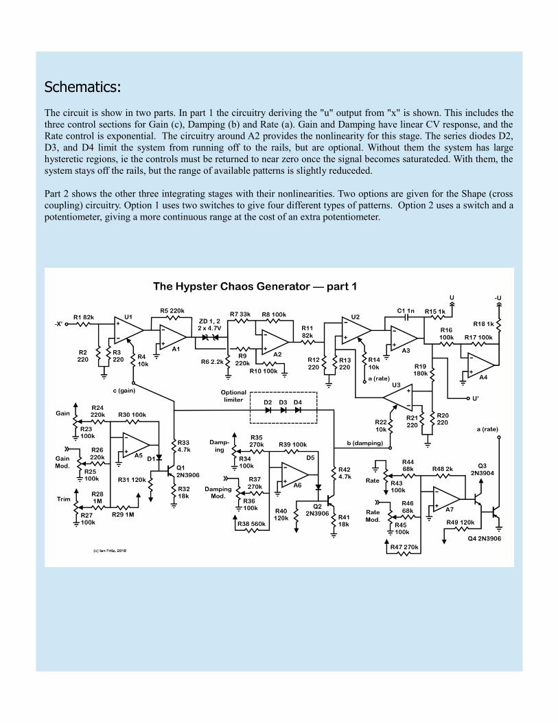
The circuit is show in two parts. In part 1 the circuitry deriving the "u" output from "x" is shown. This includes thethree control sections for Gain (c), Damping (b) and Rate (a). Gain and Damping have linear CV response, and theRate control is exponential. The circuitry around A2 provides the nonlinearity for this stage. The series diodes D2,D3, and D4 limit the system from running off to the rails, but are optional. Without them the system has largehysteretic regions, ie the controls must be returned to near zero once the signal becomes saturateded. With them, thesystem stays off the rails, but the range of available patterns is slightly reduceded.
Part 2 shows the other three integrating stages with their nonlinearities. Two options are given for the Shape (crosscoupling) circuitry. Option 1 uses two switches to give four different types of patterns. Option 2 uses a switch and apotentiometer, giving a more continuous range at the cost of an extra potentiometer.


Typical patterns:
Captured with no limiter diodes and with Shape Option 2.
Symmetric mode: xy, yz, zu
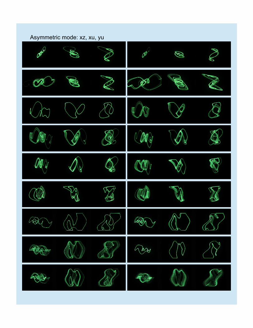
Asymmetric mode: xz, xu, yu


Notes:
The Hypster is a distant cousin to the cyclic chaos system developed several years ago and discussed on my website.The cyclic system is a wonderful chaos generator, but proper operation requires careful and tedious trimmingadjustments to make all stages behave exactly the same. In addition, the system easily diverges (runs off to therails) and requires extra active circuitry to to detect large excursions and reset the system when they occur.
The Hypster also consists of integrator stages (four) connected in a ring. However three of the integrators have fixeddamping, as opposed to the per-stage voltage-controlled damping of the cyclic system, greatly simplifying thedesign and operation. No special trimming adjustments are necessary. The issue of system divergences is solvedwith a simple passive diode switching arrangement. Just one of the four stages has voltage-controlled gain anddamping (U1 and U3 on the schematic).
The chaotic character of the system is defined by the four nonlinear (NL) circuits. These are relatively simplecircuits based on diode and zener-diode switching characteristics. Two of the nonlinearities produce functionsapproximating an x-x^3 behavior, as used in the cyclic system and my other chaos generators. The two othernonlinearities use (offset) breakpoint singularities.
Simulations run on a spreadsheet program were used to determine the parameters of the NL elements, as thereappears to be no previous studies of this system. Parameters were varied in the simulations until a useful range ofsignals was determined, and the circuit elements were then chosen correspondingly.
Finally, the cross-coupling arrangements for the two Shape options were determined empirically; basically a circuit-bending operation. Option 2 was used in obtaining the Lissajous patterns shown above. (The limiting diodes werealso disconnected.) The distinction between the "fat" and "slim" patterns is easily seen. The "symmetric" patternscan be seen to have (nearly) 180 degree rotational symmetry. The others are more lopsided.