the hive mind at uc davis
TRANSCRIPT

Below C Level: An Introduction to Computer Systems
Norm MatloffUniversity of California, Davis
This work is licensed under a Creative Commons Attribution-No Derivative Works 3.0 United States Li-cense. Copyright is retained by N. Matloff in all non-U.S. jurisdictions, but permission to use these materialsin teaching is still granted, provided the authorship and licensing information here is displayed.
Tux portion of above image drawn by [email protected] using The GIMP.

2
Author’s Biographical Sketch
Dr. Norm Matloff is a professor of computer science at the University of California at Davis, and wasformerly a professor of mathematics and statistics at that university. He is a former database softwaredeveloper in Silicon Valley, and has been a statistical consultant for firms such as the Kaiser PermanenteHealth Plan.
Dr. Matloff was born in Los Angeles, and grew up in East Los Angeles and the San Gabriel Valley. He has aPhD in pure mathematics from UCLA, specializing in probability theory and statistics. His current researchinterests are parallel processing, analysis of social networks, and regression methodology.
Prof. Matloff is a former appointed member of IFIP Working Group 11.3, an international committeeconcerned with database software security, established under UNESCO. He was a founding member ofthe UC Davis Department of Statistics, and participated in the formation of the UCD Computer ScienceDepartment as well. He is a recipient of the campuswide Distinguished Teaching Award and DistinguishedPublic Service Award at UC Davis.
Dr. Matloff is the author of two published textbooks, and of a number of widely-used Web tutorials on com-puter topics, such as the Linux operating system and the Python programming language. He and Dr. PeterSalzman are authors of The Art of Debugging with GDB, DDD, and Eclipse. Prof. Matloff’s book on the Rprogramming language, The Art of R Programming, is due to be published in 2010. He is also the author ofseveral open-source textbooks, including From Algorithms to Z-Scores: Probabilistic and Statistical Mod-eling in Computer Science (http://heather.cs.ucdavis.edu/probstatbook), and Program-ming on Parallel Machines (http://heather.cs.ucdavis.edu/˜matloff/ParProcBook.pdf).

Contents
1 Information Representation and Storage 1
1.1 Introduction . . . . . . . . . . . . . . . . . . . . . . . . . . . . . . . . . . . . . . . . . . . 1
1.2 Bits and Bytes . . . . . . . . . . . . . . . . . . . . . . . . . . . . . . . . . . . . . . . . . . 1
1.2.1 “Binary Digits” . . . . . . . . . . . . . . . . . . . . . . . . . . . . . . . . . . . . . 1
1.2.2 Hex Notation . . . . . . . . . . . . . . . . . . . . . . . . . . . . . . . . . . . . . . 2
1.2.3 There Is No Such Thing As “Hex” Storage at the Machine Level! . . . . . . . . . . 4
1.3 Main Memory Organization . . . . . . . . . . . . . . . . . . . . . . . . . . . . . . . . . . 4
1.3.1 Bytes, Words and Addresses . . . . . . . . . . . . . . . . . . . . . . . . . . . . . . 4
1.3.1.1 The Basics . . . . . . . . . . . . . . . . . . . . . . . . . . . . . . . . . . 4
1.3.1.2 Word Addresses . . . . . . . . . . . . . . . . . . . . . . . . . . . . . . . 5
1.3.1.3 “Endian-ness” . . . . . . . . . . . . . . . . . . . . . . . . . . . . . . . . 5
1.3.1.4 Other Issues . . . . . . . . . . . . . . . . . . . . . . . . . . . . . . . . . 7
1.4 Representing Information as Bit Strings . . . . . . . . . . . . . . . . . . . . . . . . . . . . 9
1.4.1 Representing Integer Data . . . . . . . . . . . . . . . . . . . . . . . . . . . . . . . 9
1.4.2 Representing Real Number Data . . . . . . . . . . . . . . . . . . . . . . . . . . . . 12
1.4.2.1 “Toy” Example . . . . . . . . . . . . . . . . . . . . . . . . . . . . . . . 13
1.4.2.2 IEEE Standard . . . . . . . . . . . . . . . . . . . . . . . . . . . . . . . . 13
1.4.3 Representing Character Data . . . . . . . . . . . . . . . . . . . . . . . . . . . . . . 15
1.4.4 Representing Machine Instructions . . . . . . . . . . . . . . . . . . . . . . . . . . . 16
i

ii CONTENTS
1.4.5 What Type of Information is Stored Here? . . . . . . . . . . . . . . . . . . . . . . . 17
1.5 Examples of the Theme, “There Are No Types at the Hardware Level” . . . . . . . . . . . . 18
1.5.1 Example . . . . . . . . . . . . . . . . . . . . . . . . . . . . . . . . . . . . . . . . 18
1.5.2 Example . . . . . . . . . . . . . . . . . . . . . . . . . . . . . . . . . . . . . . . . 19
1.5.3 Example . . . . . . . . . . . . . . . . . . . . . . . . . . . . . . . . . . . . . . . . 19
1.5.4 Example . . . . . . . . . . . . . . . . . . . . . . . . . . . . . . . . . . . . . . . . 20
1.5.5 Example . . . . . . . . . . . . . . . . . . . . . . . . . . . . . . . . . . . . . . . . 21
1.5.6 Example . . . . . . . . . . . . . . . . . . . . . . . . . . . . . . . . . . . . . . . . 22
1.6 Visual Display . . . . . . . . . . . . . . . . . . . . . . . . . . . . . . . . . . . . . . . . . . 22
1.6.1 The Basics . . . . . . . . . . . . . . . . . . . . . . . . . . . . . . . . . . . . . . . 22
1.6.2 Non-English Text . . . . . . . . . . . . . . . . . . . . . . . . . . . . . . . . . . . . 23
1.6.3 It’s the Software, Not the Hardware . . . . . . . . . . . . . . . . . . . . . . . . . . 23
1.6.4 Text Cursor Movement . . . . . . . . . . . . . . . . . . . . . . . . . . . . . . . . . 24
1.6.5 Mouse Actions . . . . . . . . . . . . . . . . . . . . . . . . . . . . . . . . . . . . . 25
1.6.6 Display of Images . . . . . . . . . . . . . . . . . . . . . . . . . . . . . . . . . . . 25
1.7 There’s Really No Such Thing As “Type” for Disk Files Either . . . . . . . . . . . . . . . . 25
1.7.1 Disk Geometry . . . . . . . . . . . . . . . . . . . . . . . . . . . . . . . . . . . . . 25
1.7.2 Definitions of “Text File” and “Binary File” . . . . . . . . . . . . . . . . . . . . . . 26
1.7.3 Programs That Access of Text Files . . . . . . . . . . . . . . . . . . . . . . . . . . 27
1.7.4 Programs That Access “Binary” Files . . . . . . . . . . . . . . . . . . . . . . . . . 28
1.8 Storage of Variables in HLL Programs . . . . . . . . . . . . . . . . . . . . . . . . . . . . . 28
1.8.1 What Are HLL Variables, Anyway? . . . . . . . . . . . . . . . . . . . . . . . . . . 28
1.8.2 Order of Storage . . . . . . . . . . . . . . . . . . . . . . . . . . . . . . . . . . . . 29
1.8.2.1 Scalar Types . . . . . . . . . . . . . . . . . . . . . . . . . . . . . . . . . 29
1.8.2.2 Complex Data Structures . . . . . . . . . . . . . . . . . . . . . . . . . . 30
1.8.2.3 Pointer Variables . . . . . . . . . . . . . . . . . . . . . . . . . . . . . . . 31
1.8.3 Local Variables . . . . . . . . . . . . . . . . . . . . . . . . . . . . . . . . . . . . . 33

CONTENTS iii
1.8.4 Variable Names and Types Are Imaginary . . . . . . . . . . . . . . . . . . . . . . . 33
1.8.5 Segmentation Faults and Bus Errors . . . . . . . . . . . . . . . . . . . . . . . . . . 35
1.9 ASCII Table . . . . . . . . . . . . . . . . . . . . . . . . . . . . . . . . . . . . . . . . . . . 37
1.10 An Example of How One Can Exploit Big-Endian Machines for Fast Character String Sorting 38
1.11 How to Inspect the Bits of a Floating-Point Variable . . . . . . . . . . . . . . . . . . . . . . 39
2 Major Components of Computer “Engines” 41
2.1 Introduction . . . . . . . . . . . . . . . . . . . . . . . . . . . . . . . . . . . . . . . . . . . 41
2.2 Major Hardware Components of the Engine . . . . . . . . . . . . . . . . . . . . . . . . . . 42
2.2.1 System Components . . . . . . . . . . . . . . . . . . . . . . . . . . . . . . . . . . 42
2.2.2 CPU Components . . . . . . . . . . . . . . . . . . . . . . . . . . . . . . . . . . . 45
2.2.2.1 Intel/Generic Components . . . . . . . . . . . . . . . . . . . . . . . . . . 45
2.2.2.2 History of Intel CPU Structure . . . . . . . . . . . . . . . . . . . . . . . 48
2.2.3 The CPU Fetch/Execute Cycle . . . . . . . . . . . . . . . . . . . . . . . . . . . . . 49
2.3 Software Components of the Computer “Engine” . . . . . . . . . . . . . . . . . . . . . . . 50
2.4 Speed of a Computer “Engine” . . . . . . . . . . . . . . . . . . . . . . . . . . . . . . . . . 51
2.4.1 CPU Architecture . . . . . . . . . . . . . . . . . . . . . . . . . . . . . . . . . . . . 51
2.4.2 Parallel Operations . . . . . . . . . . . . . . . . . . . . . . . . . . . . . . . . . . . 52
2.4.3 Clock Rate . . . . . . . . . . . . . . . . . . . . . . . . . . . . . . . . . . . . . . . 53
2.4.4 Memory Caches . . . . . . . . . . . . . . . . . . . . . . . . . . . . . . . . . . . . 54
2.4.4.1 Need for Caching . . . . . . . . . . . . . . . . . . . . . . . . . . . . . . 54
2.4.4.2 Basic Idea of a Cache . . . . . . . . . . . . . . . . . . . . . . . . . . . . 54
2.4.4.3 Blocks and Lines . . . . . . . . . . . . . . . . . . . . . . . . . . . . . . 55
2.4.4.4 Direct-Mapped Policy . . . . . . . . . . . . . . . . . . . . . . . . . . . . 56
2.4.4.5 What About Writes? . . . . . . . . . . . . . . . . . . . . . . . . . . . . . 56
2.4.4.6 Programmability . . . . . . . . . . . . . . . . . . . . . . . . . . . . . . . 57
2.4.4.7 Details on the Tag and Misc. Line Information . . . . . . . . . . . . . . . 57

iv CONTENTS
2.4.4.8 Why Caches Usually Work So Well . . . . . . . . . . . . . . . . . . . . . 58
2.4.5 Disk Caches . . . . . . . . . . . . . . . . . . . . . . . . . . . . . . . . . . . . . . 58
2.4.6 Web Caches . . . . . . . . . . . . . . . . . . . . . . . . . . . . . . . . . . . . . . . 58
3 Introduction to Linux Intel Assembly Language 61
3.1 Overview of Intel CPUs . . . . . . . . . . . . . . . . . . . . . . . . . . . . . . . . . . . . . 61
3.1.1 Computer Organization . . . . . . . . . . . . . . . . . . . . . . . . . . . . . . . . . 61
3.1.2 CPU Architecture . . . . . . . . . . . . . . . . . . . . . . . . . . . . . . . . . . . . 62
3.1.3 The Intel Architecture . . . . . . . . . . . . . . . . . . . . . . . . . . . . . . . . . 62
3.2 What Is Assembly Language? . . . . . . . . . . . . . . . . . . . . . . . . . . . . . . . . . 63
3.3 Different Assemblers . . . . . . . . . . . . . . . . . . . . . . . . . . . . . . . . . . . . . . 64
3.4 Sample Program . . . . . . . . . . . . . . . . . . . . . . . . . . . . . . . . . . . . . . . . . 64
3.4.1 Analysis . . . . . . . . . . . . . . . . . . . . . . . . . . . . . . . . . . . . . . . . 65
3.4.2 Source and Destination Operands . . . . . . . . . . . . . . . . . . . . . . . . . . . 70
3.4.3 Remember: No Names, No Types at the Machine Level . . . . . . . . . . . . . . . . 70
3.4.4 Dynamic Memory Is Just an Illusion . . . . . . . . . . . . . . . . . . . . . . . . . . 71
3.5 Use of Registers Versus Memory . . . . . . . . . . . . . . . . . . . . . . . . . . . . . . . . 72
3.6 Another Example . . . . . . . . . . . . . . . . . . . . . . . . . . . . . . . . . . . . . . . . 72
3.7 Addressing Modes . . . . . . . . . . . . . . . . . . . . . . . . . . . . . . . . . . . . . . . 76
3.8 Assembling and Linking into an Executable File . . . . . . . . . . . . . . . . . . . . . . . . 77
3.8.1 Assembler Command-Line Syntax . . . . . . . . . . . . . . . . . . . . . . . . . . . 77
3.8.2 Linking . . . . . . . . . . . . . . . . . . . . . . . . . . . . . . . . . . . . . . . . . 78
3.8.3 Makefiles . . . . . . . . . . . . . . . . . . . . . . . . . . . . . . . . . . . . . . . . 78
3.9 How to Execute Those Sample Programs . . . . . . . . . . . . . . . . . . . . . . . . . . . . 79
3.9.1 “Normal” Execution Won’t Work . . . . . . . . . . . . . . . . . . . . . . . . . . . 79
3.9.2 Running Our Assembly Programs Using GDB/DDD . . . . . . . . . . . . . . . . . 80
3.9.2.1 Using DDD for Executing Our Assembly Programs . . . . . . . . . . . . 80

CONTENTS v
3.9.2.2 Using GDB for Executing Our Assembly Programs . . . . . . . . . . . . 81
3.10 How to Debug Assembly Language Programs . . . . . . . . . . . . . . . . . . . . . . . . . 82
3.10.1 Use a Debugging Tool for ALL of Your Programming, in EVERY Class . . . . . . . 82
3.10.2 General Principles . . . . . . . . . . . . . . . . . . . . . . . . . . . . . . . . . . . 83
3.10.2.1 The Principle of Confirmation . . . . . . . . . . . . . . . . . . . . . . . . 83
3.10.2.2 Don’t Just WriteTop-Down, But DebugThat Way Too . . . . . . . . . . . 83
3.10.3 Assembly Language-Specific Tips . . . . . . . . . . . . . . . . . . . . . . . . . . . 83
3.10.3.1 Know Where Your Data Is . . . . . . . . . . . . . . . . . . . . . . . . . . 83
3.10.3.2 Seg Faults . . . . . . . . . . . . . . . . . . . . . . . . . . . . . . . . . . 84
3.10.4 Use of DDD for Debugging Assembly Programs . . . . . . . . . . . . . . . . . . . 85
3.10.5 Use of GDB for Debugging Assembly Programs . . . . . . . . . . . . . . . . . . . 85
3.10.5.1 Assembly-Language Commands . . . . . . . . . . . . . . . . . . . . . . 85
3.10.5.2 TUI Mode . . . . . . . . . . . . . . . . . . . . . . . . . . . . . . . . . . 87
3.10.5.3 CGDB . . . . . . . . . . . . . . . . . . . . . . . . . . . . . . . . . . . . 87
3.11 Some More Operand Sizes . . . . . . . . . . . . . . . . . . . . . . . . . . . . . . . . . . . 88
3.12 Some More Addressing Modes . . . . . . . . . . . . . . . . . . . . . . . . . . . . . . . . . 89
3.13 Inline Assembly Code for C++ . . . . . . . . . . . . . . . . . . . . . . . . . . . . . . . . . 92
3.14 Example: Counting Lower-Case letters . . . . . . . . . . . . . . . . . . . . . . . . . . . . . 93
3.15 “Linux Intel Assembly Language”: Why “Intel”? Why “Linux”? . . . . . . . . . . . . . . . 94
3.16 Viewing the Assembly Language Version of the Compiled Code . . . . . . . . . . . . . . . 94
3.17 String Operations . . . . . . . . . . . . . . . . . . . . . . . . . . . . . . . . . . . . . . . . 95
3.18 Useful Web Links . . . . . . . . . . . . . . . . . . . . . . . . . . . . . . . . . . . . . . . . 97
3.19 Top-Down Programming . . . . . . . . . . . . . . . . . . . . . . . . . . . . . . . . . . . . 97
4 More on Intel Arithmetic and Logic Operations 99
4.1 Instructions for Multiplication and Division . . . . . . . . . . . . . . . . . . . . . . . . . . 99
4.1.1 Multiplication . . . . . . . . . . . . . . . . . . . . . . . . . . . . . . . . . . . . . . 99

vi CONTENTS
4.1.1.1 The IMUL Instruction . . . . . . . . . . . . . . . . . . . . . . . . . . . . 99
4.1.1.2 Issues of Sign . . . . . . . . . . . . . . . . . . . . . . . . . . . . . . . . 100
4.1.2 Division . . . . . . . . . . . . . . . . . . . . . . . . . . . . . . . . . . . . . . . . . 100
4.1.2.1 The IDIV Instruction . . . . . . . . . . . . . . . . . . . . . . . . . . . . 100
4.1.2.2 Issues of Sign . . . . . . . . . . . . . . . . . . . . . . . . . . . . . . . . 100
4.1.3 Example . . . . . . . . . . . . . . . . . . . . . . . . . . . . . . . . . . . . . . . . 101
4.2 More on Carry and Overflow, and More Jump Instructions . . . . . . . . . . . . . . . . . . 102
4.3 Logical Instructions . . . . . . . . . . . . . . . . . . . . . . . . . . . . . . . . . . . . . . . 104
4.4 Floating-Point . . . . . . . . . . . . . . . . . . . . . . . . . . . . . . . . . . . . . . . . . . 108
5 Introduction to Intel Machine Language 111
5.1 Overview . . . . . . . . . . . . . . . . . . . . . . . . . . . . . . . . . . . . . . . . . . . . 111
5.2 Relation of Assembly Language to Machine Language . . . . . . . . . . . . . . . . . . . . 111
5.3 Example Program . . . . . . . . . . . . . . . . . . . . . . . . . . . . . . . . . . . . . . . . 112
5.3.1 The Code . . . . . . . . . . . . . . . . . . . . . . . . . . . . . . . . . . . . . . . . 112
5.3.2 Feedback from the Assembler . . . . . . . . . . . . . . . . . . . . . . . . . . . . . 114
5.3.3 A Few Instruction Formats . . . . . . . . . . . . . . . . . . . . . . . . . . . . . . . 114
5.3.4 Format and Operation of Jump Instructions . . . . . . . . . . . . . . . . . . . . . . 115
5.3.5 Other Issues . . . . . . . . . . . . . . . . . . . . . . . . . . . . . . . . . . . . . . . 116
5.4 It Really Is Just a Mechanical Process . . . . . . . . . . . . . . . . . . . . . . . . . . . . . 117
5.5 You Could Write an Assembler! . . . . . . . . . . . . . . . . . . . . . . . . . . . . . . . . 118
6 Compilation and Linking Process 119
6.1 GCC Operations . . . . . . . . . . . . . . . . . . . . . . . . . . . . . . . . . . . . . . . . . 119
6.1.1 The C Preprocessor . . . . . . . . . . . . . . . . . . . . . . . . . . . . . . . . . . . 119
6.1.2 The Actual Compiler, CC1, and the Assembler, AS . . . . . . . . . . . . . . . . . . 120
6.2 The Linker: What Is Linked? . . . . . . . . . . . . . . . . . . . . . . . . . . . . . . . . . . 121

CONTENTS vii
6.3 Headers in Executable Files . . . . . . . . . . . . . . . . . . . . . . . . . . . . . . . . . . . 121
6.4 Libraries . . . . . . . . . . . . . . . . . . . . . . . . . . . . . . . . . . . . . . . . . . . . . 122
6.5 A Look at the Final Product . . . . . . . . . . . . . . . . . . . . . . . . . . . . . . . . . . . 124
7 Subroutines on Intel CPUs 127
7.1 Overview . . . . . . . . . . . . . . . . . . . . . . . . . . . . . . . . . . . . . . . . . . . . 127
7.2 Stacks . . . . . . . . . . . . . . . . . . . . . . . . . . . . . . . . . . . . . . . . . . . . . . 127
7.3 CALL, RET Instructions . . . . . . . . . . . . . . . . . . . . . . . . . . . . . . . . . . . . 129
7.4 Arguments . . . . . . . . . . . . . . . . . . . . . . . . . . . . . . . . . . . . . . . . . . . . 129
7.5 Ensuring Correct Access to the Stack . . . . . . . . . . . . . . . . . . . . . . . . . . . . . . 130
7.6 Cleaning Up the Stack . . . . . . . . . . . . . . . . . . . . . . . . . . . . . . . . . . . . . 131
7.7 Full Examples . . . . . . . . . . . . . . . . . . . . . . . . . . . . . . . . . . . . . . . . . . 131
7.7.1 First Example . . . . . . . . . . . . . . . . . . . . . . . . . . . . . . . . . . . . . . 131
7.7.2 If the PC Points to Garbage, the Machine Will Happily “Execute” the Garbage . . . 134
7.7.3 Second Example . . . . . . . . . . . . . . . . . . . . . . . . . . . . . . . . . . . . 135
7.8 Interfacing C/C++ to Assembly Language . . . . . . . . . . . . . . . . . . . . . . . . . . . 136
7.8.1 Example . . . . . . . . . . . . . . . . . . . . . . . . . . . . . . . . . . . . . . . . 137
7.8.2 Cleaning Up the Stack? . . . . . . . . . . . . . . . . . . . . . . . . . . . . . . . . . 140
7.8.3 More Sections . . . . . . . . . . . . . . . . . . . . . . . . . . . . . . . . . . . . . 140
7.8.4 Multiple Arguments . . . . . . . . . . . . . . . . . . . . . . . . . . . . . . . . . . 141
7.8.5 Nonvoid Return Values . . . . . . . . . . . . . . . . . . . . . . . . . . . . . . . . . 141
7.8.6 Calling C and the C Library from Assembly Language . . . . . . . . . . . . . . . . 142
7.8.7 Local Variables . . . . . . . . . . . . . . . . . . . . . . . . . . . . . . . . . . . . . 143
7.8.8 Use of EBP . . . . . . . . . . . . . . . . . . . . . . . . . . . . . . . . . . . . . . . 144
7.8.8.1 GCC Calling Convention . . . . . . . . . . . . . . . . . . . . . . . . . . 144
7.8.8.2 The Stack Frame for a Given Call . . . . . . . . . . . . . . . . . . . . . . 144
7.8.8.3 The Stack Frames Are Chained . . . . . . . . . . . . . . . . . . . . . . . 145

viii CONTENTS
7.8.8.4 ENTER and LEAVE Instructions . . . . . . . . . . . . . . . . . . . . . . 147
7.8.8.5 Application of Stack Frame Structure . . . . . . . . . . . . . . . . . . . . 147
7.8.9 The LEA Instruction Family . . . . . . . . . . . . . . . . . . . . . . . . . . . . . . 149
7.8.10 The Function main() IS a Function, So It Too Has a Stack Frame . . . . . . . . . . . 150
7.8.11 Once Again, There Are No Types at the Hardware Level! . . . . . . . . . . . . . . . 152
7.8.12 What About C++? . . . . . . . . . . . . . . . . . . . . . . . . . . . . . . . . . . . 153
7.8.13 Putting It All Together . . . . . . . . . . . . . . . . . . . . . . . . . . . . . . . . . 154
7.9 Subroutine Calls/Returns Are “Expensive” . . . . . . . . . . . . . . . . . . . . . . . . . . . 157
7.10 Debugging Assembly Language Subroutines . . . . . . . . . . . . . . . . . . . . . . . . . . 158
7.10.1 Focus on the Stack . . . . . . . . . . . . . . . . . . . . . . . . . . . . . . . . . . . 158
7.10.2 A Special Consideration When Interfacing C/C++ with Assembly Language . . . . 158
7.11 Macros . . . . . . . . . . . . . . . . . . . . . . . . . . . . . . . . . . . . . . . . . . . . . 159
7.12 Inline Assembly Code for C++ . . . . . . . . . . . . . . . . . . . . . . . . . . . . . . . . . 163
8 Overview of Input/Output Mechanisms 165
8.1 Introduction . . . . . . . . . . . . . . . . . . . . . . . . . . . . . . . . . . . . . . . . . . . 165
8.2 I/O Ports and Device Structure . . . . . . . . . . . . . . . . . . . . . . . . . . . . . . . . . 166
8.3 Program Access to I/O Ports . . . . . . . . . . . . . . . . . . . . . . . . . . . . . . . . . . 166
8.3.1 I/O Address Space Approach . . . . . . . . . . . . . . . . . . . . . . . . . . . . . . 166
8.3.2 Memory-Mapped I/O Approach . . . . . . . . . . . . . . . . . . . . . . . . . . . . 167
8.4 Wait-Loop I/O . . . . . . . . . . . . . . . . . . . . . . . . . . . . . . . . . . . . . . . . . . 168
8.5 PC Keyboards . . . . . . . . . . . . . . . . . . . . . . . . . . . . . . . . . . . . . . . . . . 169
8.6 Interrupt-Driven I/O . . . . . . . . . . . . . . . . . . . . . . . . . . . . . . . . . . . . . . . 169
8.6.1 Telephone Analogy . . . . . . . . . . . . . . . . . . . . . . . . . . . . . . . . . . . 169
8.6.2 What Happens When an Interrupt Occurs? . . . . . . . . . . . . . . . . . . . . . . 170
8.6.3 Alternative Designs . . . . . . . . . . . . . . . . . . . . . . . . . . . . . . . . . . . 171
8.6.4 Glimpse of an ISR . . . . . . . . . . . . . . . . . . . . . . . . . . . . . . . . . . . 172
CONTENTS ix
8.6.5 I/O Protection . . . . . . . . . . . . . . . . . . . . . . . . . . . . . . . . . . . . . . 172
8.6.6 Distinguishing Among Devices . . . . . . . . . . . . . . . . . . . . . . . . . . . . 173
8.6.6.1 How Does the CPU Know Which I/O Device Requested the Interrupt? . . 173
8.6.6.2 How Does the CPU Know Where the ISR Is? . . . . . . . . . . . . . . . 173
8.6.6.3 Revised Interrupt Sequence . . . . . . . . . . . . . . . . . . . . . . . . . 173
8.6.7 How Do PCs Prioritize Interrupts from Different Devices? . . . . . . . . . . . . . . 174
8.7 Direct Memory Access (DMA) . . . . . . . . . . . . . . . . . . . . . . . . . . . . . . . . . 175
8.8 Disk Structure . . . . . . . . . . . . . . . . . . . . . . . . . . . . . . . . . . . . . . . . . . 175
8.9 USB Devices . . . . . . . . . . . . . . . . . . . . . . . . . . . . . . . . . . . . . . . . . . 176
9 Overview of Functions of an Operating System 177
9.1 Introduction . . . . . . . . . . . . . . . . . . . . . . . . . . . . . . . . . . . . . . . . . . . 177
9.1.1 It’s Just a Program! . . . . . . . . . . . . . . . . . . . . . . . . . . . . . . . . . . . 177
9.1.2 What Is an OS for, Anyway? . . . . . . . . . . . . . . . . . . . . . . . . . . . . . . 178
9.2 Application Program Loading . . . . . . . . . . . . . . . . . . . . . . . . . . . . . . . . . 180
9.2.1 Basic Operations . . . . . . . . . . . . . . . . . . . . . . . . . . . . . . . . . . . . 180
9.2.2 Chains of Programs Calling Programs . . . . . . . . . . . . . . . . . . . . . . . . . 181
9.2.3 Static Versus Dynaming Linking . . . . . . . . . . . . . . . . . . . . . . . . . . . . 181
9.2.4 Making These Concepts Concrete: Commands You Can Try Yourself . . . . . . . . 182
9.2.4.1 Mini-Example . . . . . . . . . . . . . . . . . . . . . . . . . . . . . . . . 182
9.2.4.2 The strace Command . . . . . . . . . . . . . . . . . . . . . . . . . . . . 182
9.3 OS Bootup . . . . . . . . . . . . . . . . . . . . . . . . . . . . . . . . . . . . . . . . . . . 183
9.4 Timesharing . . . . . . . . . . . . . . . . . . . . . . . . . . . . . . . . . . . . . . . . . . . 184
9.4.1 Many Processes, Taking Turns . . . . . . . . . . . . . . . . . . . . . . . . . . . . . 184
9.4.2 Example of OS Code: Linux for Intel CPUs . . . . . . . . . . . . . . . . . . . . . . 185
9.4.3 Process States . . . . . . . . . . . . . . . . . . . . . . . . . . . . . . . . . . . . . . 187
9.4.4 What About Background Jobs? . . . . . . . . . . . . . . . . . . . . . . . . . . . . 188

x CONTENTS
9.4.5 Threads: “Lightweight Processes” . . . . . . . . . . . . . . . . . . . . . . . . . . . 189
9.4.5.1 The Mechanics . . . . . . . . . . . . . . . . . . . . . . . . . . . . . . . . 189
9.4.5.2 Threads Example . . . . . . . . . . . . . . . . . . . . . . . . . . . . . . 190
9.4.6 Making These Concepts Concrete: Commands You Can Try Yourself . . . . . . . . 192
9.5 Virtual Memory . . . . . . . . . . . . . . . . . . . . . . . . . . . . . . . . . . . . . . . . . 194
9.5.1 Make Sure You Understand the Goals . . . . . . . . . . . . . . . . . . . . . . . . . 194
9.5.1.1 Overcome Limitations on Memory Size . . . . . . . . . . . . . . . . . . 194
9.5.1.2 Relieve the Compiler and Linker of Having to Deal with Real Addresses . 194
9.5.1.3 Enable Security . . . . . . . . . . . . . . . . . . . . . . . . . . . . . . . 195
9.5.2 The Virtual Nature of Addresses . . . . . . . . . . . . . . . . . . . . . . . . . . . . 195
9.5.3 Overview of How the Goals Are Achieved . . . . . . . . . . . . . . . . . . . . . . 196
9.5.3.1 Overcoming Limitations on Memory Size . . . . . . . . . . . . . . . . . 196
9.5.3.2 Relieving the Compiler and Linker of Having to Deal with Real Addresses 197
9.5.3.3 Enabling Security . . . . . . . . . . . . . . . . . . . . . . . . . . . . . . 197
9.5.4 Who Does What When? . . . . . . . . . . . . . . . . . . . . . . . . . . . . . . . . 198
9.5.5 Details on Usage of the Page Table . . . . . . . . . . . . . . . . . . . . . . . . . . 199
9.5.5.1 Virtual-to-Physical Address Translation, Page Table Lookup . . . . . . . . 199
9.5.5.2 Layout of the Page Table . . . . . . . . . . . . . . . . . . . . . . . . . . 200
9.5.5.3 Page Faults . . . . . . . . . . . . . . . . . . . . . . . . . . . . . . . . . . 202
9.5.5.4 Access Violations . . . . . . . . . . . . . . . . . . . . . . . . . . . . . . 202
9.5.6 VM and Context Switches . . . . . . . . . . . . . . . . . . . . . . . . . . . . . . . 204
9.5.7 Improving Performance—TLBs . . . . . . . . . . . . . . . . . . . . . . . . . . . . 204
9.5.8 The Role of Caches in VM Systems . . . . . . . . . . . . . . . . . . . . . . . . . . 205
9.5.8.1 Addressing . . . . . . . . . . . . . . . . . . . . . . . . . . . . . . . . . . 205
9.5.8.2 Hardware Vs. Software . . . . . . . . . . . . . . . . . . . . . . . . . . . 206
9.5.9 Making These Concepts Concrete: Commands You Can Try Yourself . . . . . . . . 206
9.6 A Bit More on System Calls . . . . . . . . . . . . . . . . . . . . . . . . . . . . . . . . . . 207

CONTENTS xi
9.7 OS File Management . . . . . . . . . . . . . . . . . . . . . . . . . . . . . . . . . . . . . . 209
9.8 To Learn More . . . . . . . . . . . . . . . . . . . . . . . . . . . . . . . . . . . . . . . . . 209
9.9 Intel Pentium Architecture . . . . . . . . . . . . . . . . . . . . . . . . . . . . . . . . . . . 210
10 Example of RISC Architecture: MIPS 211
10.1 Introduction . . . . . . . . . . . . . . . . . . . . . . . . . . . . . . . . . . . . . . . . . . . 211
10.2 A Definition of RISC . . . . . . . . . . . . . . . . . . . . . . . . . . . . . . . . . . . . . . 213
10.3 Beneficial Effects for Compiler Writers . . . . . . . . . . . . . . . . . . . . . . . . . . . . 214
10.4 Introduction to the MIPS Architecture . . . . . . . . . . . . . . . . . . . . . . . . . . . . . 214
10.4.1 Register Set . . . . . . . . . . . . . . . . . . . . . . . . . . . . . . . . . . . . . . . 215
10.4.2 Example Code . . . . . . . . . . . . . . . . . . . . . . . . . . . . . . . . . . . . . 215
10.4.3 MIPS Assembler Pseudoinstructions . . . . . . . . . . . . . . . . . . . . . . . . . . 217
10.4.4 Programs Tend to Be Longer on RISC Machines . . . . . . . . . . . . . . . . . . . 219
10.4.5 Instruction Formats . . . . . . . . . . . . . . . . . . . . . . . . . . . . . . . . . . . 219
10.4.6 Arithmetic and Logic Instruction Set . . . . . . . . . . . . . . . . . . . . . . . . . . 221
10.4.7 Conditional Branches in MIPS . . . . . . . . . . . . . . . . . . . . . . . . . . . . . 221
10.5 Some MIPS Op Codes . . . . . . . . . . . . . . . . . . . . . . . . . . . . . . . . . . . . . 222
10.6 Dealing with Branch Delays . . . . . . . . . . . . . . . . . . . . . . . . . . . . . . . . . . 222
10.6.1 Branch Prediction . . . . . . . . . . . . . . . . . . . . . . . . . . . . . . . . . . . . 222
10.6.2 Delayed Branch . . . . . . . . . . . . . . . . . . . . . . . . . . . . . . . . . . . . . 223
11 The Java Virtual Machine 225
11.1 Background Needed . . . . . . . . . . . . . . . . . . . . . . . . . . . . . . . . . . . . . . . 225
11.2 Goal . . . . . . . . . . . . . . . . . . . . . . . . . . . . . . . . . . . . . . . . . . . . . . . 225
11.3 Why Is It a “Virtual” Machine? . . . . . . . . . . . . . . . . . . . . . . . . . . . . . . . . . 225
11.4 The JVM Architecture . . . . . . . . . . . . . . . . . . . . . . . . . . . . . . . . . . . . . 226
11.4.1 Registers . . . . . . . . . . . . . . . . . . . . . . . . . . . . . . . . . . . . . . . . 227

xii CONTENTS
11.4.2 Memory Areas . . . . . . . . . . . . . . . . . . . . . . . . . . . . . . . . . . . . . 228
11.5 First Example . . . . . . . . . . . . . . . . . . . . . . . . . . . . . . . . . . . . . . . . . . 229
11.5.1 Java Considerations . . . . . . . . . . . . . . . . . . . . . . . . . . . . . . . . . . . 229
11.5.2 How to Inspect the JVM Code . . . . . . . . . . . . . . . . . . . . . . . . . . . . . 230
11.5.3 The Local Variables Section of main() . . . . . . . . . . . . . . . . . . . . . . . . . 231
11.5.4 The Call of Min() from main() . . . . . . . . . . . . . . . . . . . . . . . . . . . . . 231
11.5.5 Accessing Arguments from within Min() . . . . . . . . . . . . . . . . . . . . . . . 232
11.5.6 Details on the Action of Jumps . . . . . . . . . . . . . . . . . . . . . . . . . . . . . 233
11.5.7 Multibyte Numbers Embedded in Instructions . . . . . . . . . . . . . . . . . . . . . 233
11.5.8 Calling Instance Methods . . . . . . . . . . . . . . . . . . . . . . . . . . . . . . . 233
11.5.9 Creating and Accessing Arrays . . . . . . . . . . . . . . . . . . . . . . . . . . . . . 235
11.5.10 Constructors . . . . . . . . . . . . . . . . . . . . . . . . . . . . . . . . . . . . . . 236
11.5.11 Philosophy Behind the Design of the JVM . . . . . . . . . . . . . . . . . . . . . . . 236
11.5.11.1 Instruction Structure . . . . . . . . . . . . . . . . . . . . . . . . . . . . . 236
11.5.11.2 Stack Architecture . . . . . . . . . . . . . . . . . . . . . . . . . . . . . . 236
11.5.11.3 Safety . . . . . . . . . . . . . . . . . . . . . . . . . . . . . . . . . . . . 237
11.6 Another Example . . . . . . . . . . . . . . . . . . . . . . . . . . . . . . . . . . . . . . . . 237
11.7 Yet Another Example . . . . . . . . . . . . . . . . . . . . . . . . . . . . . . . . . . . . . . 240
11.8 Overview of JVM Instructions . . . . . . . . . . . . . . . . . . . . . . . . . . . . . . . . . 247
11.9 References . . . . . . . . . . . . . . . . . . . . . . . . . . . . . . . . . . . . . . . . . . . . 252

Chapter 1
Information Representation and Storage
1.1 Introduction
A computer can store many types of information. A high-level language (HLL) will typically have severaldata types, such as the C/C++ language’s int, float, and char. Yet a computer can not directly store anyof these data types. Instead, a computer only stores 0s and 1s. Thus the question arises as to how one canrepresent the abstract data types of C/C++ or other HLLs in terms of 0s and 1s. What, for example, does achar variable look like when viewed from “under the hood”?
A related question is how we can use 0s and 1s to represent our program itself, meaning the machinelanguage instructions that are generated when our C/C++ or other HLL program is compiled. In this chapter,we will discuss how to represent various types of information in terms of 0s and 1s. And, in addition to thisquestion of how items are stored, we will also begin to address the question of where they are stored, i.e.where they are placed within the structure of a computer’s main memory.
1.2 Bits and Bytes
1.2.1 “Binary Digits”
The 0s and 1s used to store information in a computer are called bits. The term comes from binary digit,i.e. a digit in the base-2 form of a number (though once again, keep in mind that not all kinds of items thata computer stores are numeric). The physical nature of bit storage, such as using a high voltage to representa 1 and a low voltage to represent a 0, is beyond the scope of this book, but the point is that every piece ofinformation must be expressed as a string of bits.
1

2 CHAPTER 1. INFORMATION REPRESENTATION AND STORAGE
For most computers, it is customary to label individual bits within a bit string from right to left, starting with0. For example, in the bit string 1101, we say Bit 0 = 1, Bit 1 = 0, Bit 2 = 1 and Bit 3 = 1.
If we happen to be using an n-bit string to represent a nonnegative integer, we say that Bit n-1, i.e. theleftmost bit, is the most significant bit (MSB). To see why this terminology makes sense, think of the base-10 case. Suppose the price of an item is $237. A mistake by a sales clerk in the digit 2 would be muchmore serious than a mistake in the digit 7, i.e. the 2 is the most significant of the three digits in this price.Similarly, in an n-bit string, Bit 0, the rightmost bit, is called the least significant bit (LSB).
A bit is said to be set if it is 1, and cleared if it is 0.
A string of eight bits is usually called a byte. Bit strings of eight bits are important for two reasons. First,in storing characters, we typically store each character as an 8-bit string. Second, computer storage cells aretypically composed of an integral number of bytes, i.e. an even multiple of eight bits, with 16 bits and 32bits being the most commonly encountered cell sizes.
The whimsical pioneers of the computer world extended the pun, “byte” to the term nibble, meaning a 4-bitstring. So, each hex digit (see below) is called a nibble.
1.2.2 Hex Notation
We will need to define a “shorthand” notation to use for writing long bit strings. For example, imagine howcumbersome it would be for us humans to keep reading and writing a string such as 1001110010101110.So, let us agree to use hexadecimal notation, which consists of grouping a bit string into 4-bit substrings,and then giving a single-character name to each substring.
For example, for the string 1001110010101110, the grouping would be
1001 1100 1010 1110
Next, we give a name to each 4-bit substring. To do this, we treat each 4-bit substring as if it were a base-2number. For example, the leftmost substring above, 1001, is the base-2 representation for the number 9,since
1 · (23) + 0 · (22) + 0 · (21) + 1 · (20) = 9,
so, for convenience we will call that substring “9.” The second substring, 1100, is the base-2 form for thenumber 12, so we will call it “12.” However, we want to use a single-character name, so we will call it “c,”because we will call 10 “a,” 11 “b,” 12 “c,” and so on, until 15, which we will call “f.”
In other words, we will refer to the string 1001110010101110 as 0x9cae. This is certainly much moreconvenient, since it involves writing only 4 characters, instead of 16 0s and 1s. However, keep in mind thatwe are doing this only as a quick shorthand form, for use by us humans. The computer is storing the string

1.2. BITS AND BYTES 3
in its original form, 1001110010101110, not as 0x9cae.
We say 0x9cae is the hexadecimal, or “hex,” form of the the bit string 1001110010101110. Often we willuse the C-language notation, prepending “0x” to signify hex, in this case 0x9cae.
Recall that we use bit strings to represent many different types of information, with some types beingnumeric and others being nonnumeric. If we happen to be using a bit string as a nonnegative number, thenthe hex form of that bit string has an additional meaning, namely the base-16 representation of that number.
For example, the above string 1001110010101110, if representing a nonnegative base-2 number, is equal to
1(215) + 0(214) + 0(213) + 1(212) + 1(211) + 1(210) + 0(29) + 0(28)+ 1(27) + 0(26) + 1(25) + 0(24) + 1(23) + 1(22) + 1(21) + 0(20) = 40, 110.
If the hex form of this bit string, 0x9cae, is treated as a base-16 number, its value is
9(163) + 12(162) + 10(161) + 14(160) = 40, 110,
verifying that indeed the hex form is the base-16 version of the number. That is in fact the origin of the term“hexadecimal,” which means “pertaining to 16.” [But there is no relation of this name to the fact that in thisparticular example our bit string is 16 bits long; we will use hexadecimal notation for strings of any length.]
The fact that the hex version of a number is also the base-16 representation of that number comes in handyin converting a binary number to its base-10 form. We could do such conversion by expanding the powersof 2 as above, but it is much faster to group the binary form into hex, and then expand the powers of 16, aswe did in the second equation.
The opposite conversion—from base-10 to binary—can be expedited in the same way, by first convertingfrom base-10 to base-16, and then degrouping the hex into binary form. The conversion of decimal to base-16 is done by repeatedly dividing by 16 until we get a quotient less than 16; the hex digits then are obtainedas the remainders and the very last quotient. To make this concrete, let’s convert the decimal number 21602to binary:
Divide 21602 by 16, yielding 1350, remainder 2.Divide 1350 by 16, yielding 84, remainder 6.Divide 84 by 16, yielding 5, remainder 4.The hex form of 21602 is thus 5462.The binary form is thus 0101 0100 0110 0010, i.e. 0101010001100010.
The main ingredient here is the repeated division by 16. By dividing by 16 again and again, we are buildingup powers of 16. For example, in the line

4 CHAPTER 1. INFORMATION REPRESENTATION AND STORAGE
Divide 1350 by 16, yielding 84, remainder 6.
above, that is our second division by 16, so it is a cumulative division by 162. [Note that this is why we aredividing by 16, not because the number has 16 bits.]
1.2.3 There Is No Such Thing As “Hex” Storage at the Machine Level!
Remember, hex is merely a convenient notation for us humans. It is wrong to say something like “Themachine stores the number in hex,” “The compiler converts the number to hex,” and so on. It is crucial thatyou avoid this kind of thinking, as it will lead to major misunderstandings later on.
1.3 Main Memory Organization
During the time a program is executing, both the program’s data and the program itself, i.e. the machineinstructions, are stored in main memory. In this section, we will introduce main memory structure. (We willusually refer to main memory as simply “memory.”)
1.3.1 Bytes, Words and Addresses
640 K ought to be enough for anybody—Bill Gates, 1981
1.3.1.1 The Basics
Memory (this means RAM/ROM) can be viewed as a long string of consecutive bytes. Each byte has anidentification number, called an address. Again, an address is just an “i.d. number,” like a Social SecurityNumber identifies a person, a license number identifies a car, and an account number identifies a bankaccount. Byte addresses are consecutive integers, so that the memory consists of Byte 0, Byte 1, Byte 2, andso on.
On each machine, a certain number of consecutive bytes is called a word. The number of bytes or bits(there are eight times as many bits as bytes, since a byte consists of eight bits) in a word in a given machineis called the machine’s word size. This is usually defined in terms of the size of number which the CPUaddition circuitry can handle, which in recent years has typically been 32 bits. In other words, the CPU’sadder inputs two 32-bit numbers, and outputs a 32-bit sum, so we say the word size is 32 bits.
Most CPUs popular today have 32-bit or 64-bit words. As of December 2006, the trend is definitely towardthe latter, with many desktop PCs having 64-bit words.

1.3. MAIN MEMORY ORGANIZATION 5
Early members of the Intel CPU family had 16-bit words, while the later ones were extended to 32-bit andthen 64-bi size. In order to ensure that programs written for the early chips would run on the later ones, Inteldesigned the later CPUs to be capable of running in several modes, one for each bit size.
Note carefully that most machines do not allow overlapping words. That means, for example, that on a32-bit machine, Bytes 0-3 will form a word and Bytes 4-7 will form a word, but Bytes 1-4 do NOT form aword. If your program tries to access the “word” consisting of Bytes 1-4, it may cause an execution error.On UNIX systems, for instance, you may get the error message “bus error.”
However, an exception to this is Intel chips, which do not require alignment on word boundaries like this.However, note that if your program uses unaligned words, each time you access such a word, the CPU mustget two words from memory, slowing things down.
Just as a bit string has its most significant and least significant bits, a word will have its most significant andleast significant bytes. To illustrate this, suppose word size is 32 bits and consider storage of the integer 25,which is
00000000000000000000000000011001
in bit form and 0x00000019 as hex. Three bytes will each contain 0x00 and the fourth 0x19, with the 0x19byte being the least significant and the first 0x00 byte being most significant.
Not only does each byte have an address, but also each word has one too. The address of a word will be theaddress of its lowest-address byte. So for instance Bytes 4-7 comprise Word 4.
1.3.1.2 Word Addresses
1.3.1.3 “Endian-ness”
Recall that the word size of a machine is the size of the largest string on which the hardware is capable ofperforming addition. A question arises as to whether the lowest-address byte in a word is treated by thehardware as the most or least significant byte.
The Intel family handles this in a little-endian manner, meaning that the least significant byte within a wordhas the lowest address. For instance, consider the above example of the integer 25. Suppose it is storedin Word 204, which on any 32-bit machine will consist of Bytes 204, 205, 206 and 207. On a 32-bit Intelmachine (or any other 32-bit little-endian machine), Byte 204 will be the least significant byte, and thus inthis example will contain 0x19.
Note carefully that when we say that Byte 204 contains the least significant byte, what this really means isthat the arithmetic hardware in our machine will treat it as such. If for example we tell the hardware to addthe contents of Word 204 and the contents of Word 520, the hardware will start at Bytes 204 and 520, not

6 CHAPTER 1. INFORMATION REPRESENTATION AND STORAGE
at Bytes 207 and 523. First Byte 204 will be added to Byte 520, recording the carry, if any. Then Byte 205will be added to Byte 521, plus the carry if any from the preceding byte addition, and so on, through Bytes207 and 523.
SPARC chips, on the other hand, assign the least significant byte to the highest address, a big-endianscheme. This is the case for IBM mainframes too, as well as for the Java Virtual Machine.
Some chips, such as MIPS and PowerPC, even give the operating system a choice as to which rules the CPUwill follow; when the OS is booted, it establishes which “endian-ness” will be used.
The endian-ness problem also arises on the Internet. If someone is running a Web browser on a little-endianmachine but the Web site’s server is big-endian, they won’t be able to communicate. Thus as a standard, theInternet uses big-endian order. There is a UNIX system call, htons(), which takes a byte string and does theconversion, if necessary.
Here is a function that can be used to test the endian-ness of the machine on which it is run:
1 int Endian() // returns 1 if the machine is little-endian, else 02
3 { int X;4 char *PC;5
6 X = 1;7 PC = (char *) &X;8 return *PC;9 }
As we will discuss in detail later, compilers usually choose to store int variables one per word, and charvariables one per byte. So, in this little program, X will occupy four bytes on a 32-bit machine, which weassume here; PC will be used to point to one of those bytes.
Suppose for example that X is in memory word 4000, so &X is 4000. Then PC will be 4000 too. Word4000 consists of bytes 4000, 4001, 4002 and 4003. Since X is 1, i.e. 000...00︸ ︷︷ ︸
31 0s
1, one of those four bytes will
contain 00000001, i.e. the value 1 and the others will contain 0. The 1 will be in byte 4000 if and only themachine is little-endian. In the return line, PC is pointing to byte 4000, so the return value will be either1 or 0, depending on whether the machine is little- or big-endian, just what we wanted.
Note that within a byte there is no endian-ness issue. Remember, the endian-ness issue is defined at theword level, in terms of addresses of bytes within words; the question at hand is, “Which byte within a wordis treated as most significant—the lowest-numbered-address byte, or the highest one?” This is because thereis no addressing of bits within a byte, thus no such issue at the byte level.
Note that a C compiler treats hex as base-16, and thus the endian-ness of the machine will be an issue. Forexample, suppose we have the code
int Z = 0x12345678;

1.3. MAIN MEMORY ORGANIZATION 7
and &Z is 240.
As we will see later, compilers usually store an int variable in one word. So, Z will occupy Bytes 240, 241,242 and 243. So far, all of this holds independent of whether the machine is big- or little-endian. But theendian-ness will affect which bytes of Z are stored in those four addresses.
On a little-endian machine, the byte 0x78, for instance, will be stored in location 240, while on a big-endianmachine it would be in location 243.
Similarly, a call to printf() with %x format will report the highest-address byte first on a little-endianmachine, but on a big-endian machine the call would report the lowest-address byte first. The reason forthis is that the C standard was written with the assumption that one would want to use % format only insituations in which the programmer intends the quantity to be an integer. Thus the endian-ness will be afactor. This is a very important point to remember if you are using a call to printf() with %x format todetermine the actual bit contents of a word which might not be intended as an integer.
There are some situations in which one can exploit the endian-ness of a machine. An example is given inSection 1.10.
1.3.1.4 Other Issues
As we saw above, the address of a word is defined to be the address of its lowest-numbered byte. Thispresents a problem: How can we specify that we want to access, say, Byte 52 instead of Word 52? Theanswer is that for machine instruction types which allow both byte and word access (some instructions do,others do not), the instruction itself will indicate whether we want to access Byte x or Word x.
For example, we mentioned earlier that the Intel instruction 0xc7070100 in 16-bit mode puts the value 1into a certain “cell” of memory. Since we now have the terms word and byte to work with, we can be morespecific than simply using the word cell: The instruction 0xc7070100 puts the value 1 into a certain wordof memory; by contrast, the instruction 0xc60701 puts the value 1 into a certain byte of memory. You willsee the details in later chapters, but for now you can see that differentiating between byte access and wordaccess is possible, and is indicated in the bit pattern of the instruction itself.
Note that the word size determines capacity, depending on what type of information we wish to store. Forexample:
(a) Suppose we are using an n-bit word to store a nonnegative integer. Then the range of numbers thatwe can store will be 0 to 2n − 1, which for n = 16 will be 0 to 65,535, and for n = 32 will be 0 to4,294,967,295.
(b) If we are storing a signed integer in an n-bit word, then the information presented in Section 1.4.1 willshow that the range will be −2n−1 to 2n−1 − 1, which will be -32,768 to +32,767 for 16-bit words,and -2,147,483,648 to +2,147,483,647 for 32-bit words.

8 CHAPTER 1. INFORMATION REPRESENTATION AND STORAGE
(c) Suppose we wish to store characters. Recall that an ASCII character will take up seven bits, not eight.But it is typical that the seven is “rounded off” to eight, with 1 bit being left unused (or used for someother purpose, such as a technique called parity, which is used to help detect errors). In that case,machines with 16-bit words can store two characters per word, while 32-bit machines can store fourcharacters per word.
(d) Suppose we are storing machine instructions. Some machines use a fixed instruction length, equal tothe word size. These are the so-called RISC machines, to be discussed in Chapter 10. On the otherhand, most older machines have instructions are of variable lengths.
On earlier Intel machines, for instance, instructions were of lengths one to six bytes (and the range hasgrown much further since then). Since the word size on those machines was 16 bits, i.e. two bytes, wesee that a memory word might contain two instructions in some cases, while in some other cases aninstruction would be spread out over several words. The instruction 0xc7070100 mentioned earlier,for example, takes up four bytes (count them!), thus two words of memory.1
It is helpful to make an analogy of memory cells (bytes or words) to bank accounts, as mentioned above.Each individual bank account has an account number and a balance. Similarly, each memory has its addressand its contents.
As with anything else in a computer, an address is given in terms of 0s and 1s, i.e. as a base-2 representationof an unsigned integer. The number of bits in an address is called the address size. Among earlier Intelmachines, the address size grew from 20 bits on the models based on the 8086 CPU, to 24 bits on the 80286model, and then to 32 bits for the 80386, 80486 and Pentium. The current trend is to 64 bits.
The address size is crucial, since it puts an upper bound on how many memory bytes our system can have. Ifthe address size is n, then addresses will range from 0 to 2n−1, so we can have at most 2n bytes of memoryin our system. It is similar to the case of automobile license plates. If for example, license plates in a certainstate consist of three letters and three digits, then there will be only 263103 = 17, 560, 000 possible plates.That would mean we could have only 17,560,000 cars and trucks in the state.
Keep in mind that an address is considered as unsigned integer. For example, suppose our address size is, tokeep the example simple, four bits. Then the address 1111 is considered to be +15, not -1.
IMPORTANT NOTATION:
We will use the notation c( ) to mean “contents of,” e.g. c(0x2b410) means the contents of memoryword 0x2b410. Keep this in mind, as we will use it throughout the course
Today it is customary to design machines with address size equal to word size. To see why this makes sense,consider this code:
int X,*P;
1Intel machinese today are still of the CISC type.

1.4. REPRESENTING INFORMATION AS BIT STRINGS 9
...P = &X;
The variable P is a pointer and thus contains an address. But P is a variable in its own right, and thus willbe stored in some word. For example, we may have &X and P equal to 200 and 344, respectively. Then wewill have c(344) = 200, i.e. an address will be stored in a word. So it makes sense to have address size equalto word size.
1.4 Representing Information as Bit Strings
We may now address the questions raised at the beginning of the chapter. How can the various abstract datatypes used in HLLs, and also the computer’s machine instructions, be represented using strings of 0s and1s?2
1.4.1 Representing Integer Data
Representing nonnegative integer values is straightforward: We just use the base-2 representation, suchas 010 for the number +2. For example, the C/C++ language data type unsigned int (also called simplyunsigned) interprets bit strings using this representation.
But what about integers which can be either positive or negative, i.e. which are signed? For example, whatabout the data type int in C?
Suppose for simplicity that we will be using 3-bit strings to store integer variables. [Note: We will assumethis size for bit strings in the next few paragraphs.] Since each bit can take on either of two values, 0 or 1,there are 23 = 8 possible 3-bit strings. So, we can represent eight different integer values. In other words,we could, for example, represent any integer from -4 to +3, or -2 to +5, or whatever. Most systems opt fora range in which about half the representable numbers are positive and about half are negative. The range-2 to +5, for example, has many more representable positive numbers than negative numbers. This might beuseful in some applications, but since most computers are designed as general-purpose machines, they useinteger representation schemes which are as symmetric around 0 as possible. The two major systems belowuse ranges of -3 to +3 and -4 to +3.
But this still leaves open the question as to which bit strings represent which numbers. The two majorsystems, signed-magnitude and 2s complement, answer this question in different ways. Both systemsstore the nonnegative numbers in the same way, by storing the base-2 form of the number: 000 represents0, 001 represents +1, 010 represents +2, and 011 represents +3. However, the two systems differ in the waythey store the negative numbers, in the following way.
2The word string here does not refer to a character string. It simply means a group of bits.

10 CHAPTER 1. INFORMATION REPRESENTATION AND STORAGE
The signed-magnitude system stores a 3-bit negative number first as a 1 bit, followed by the base-2 rep-resentation of the magnitude, i.e. absolute value, of that number. For example, consider how the number-3 would be stored. The magnitude of this number is 3, whose base-2 representation is 11. So, the 3-bit,signed-magnitude representation of -3 is 1 followed by 11, i.e. 111. The number -2 would be stored as 1followed by 10, i.e. 110, and so on. The reader should verify that the resulting range of numbers repre-sentable in three bits under this system would then be -3 to +3. The reader should also note that the number0 actually has two representations, 000 and 100. The latter could be considered “-0,” which of course hasno meaning, and 000 and 100 should be considered to be identical. Note too that we see that 100, which inan unsigned system would represent +4, does not do so here; indeed, +4 is not representable at all, since ourrange is -3 to +3.
The 2s complement system handles the negative numbers differently. To explain how, first think of stringsof three decimal digits, instead of three bits. For concreteness, think of a 3-digit odometer or trip meter inan automobile. Think about how we could store positive and negative numbers on this trip meter, if we hadthe desire to do so. Since there are 10 choices for each digit (0,1,...,9), and there are three digits, there are103 = 1000 possible patterns. So, we would be able to store numbers which are approximately in the range-500 to +500.
Suppose we can wind the odometer forward or backward with some manual control. Let us initially set theodometer to 000, i.e. set all three digits to 0. If we were to wind forward from 000 once, we would get 001;if we were to wind forward from 000 twice, we would get 002; and so on. So we would use the odometerpattern 000 to represent 0, 001 to represent +1, 002 to represent +2, ..., and 499 to represent +499. If wewere to wind backward from 000 once, we would get 999; if we were to wind backward twice, we wouldget 998; and so on. So we would use the odometer pattern 999 to represent -1, use 998 to represent -2, ...,and use 500 to represent -500 (since the odometer would read 500 if we were to wind backward 500 times).This would give us a range -500 to +499 of representable numbers.
Getting back to strings of three binary digits instead of three decimal digits, we apply the same principle. Ifwe wind backward once from 000, we get 111, so we use 111 to represent -1. If we wind backward twicefrom 000, we get 110, so 110 will be used to represent -2. Similarly, 101 will mean -3, and 100 will mean-4. If we wind backward one more time, we get 011, which we already reserved to represent +3, so -4 willbe our most negative representable number. So, under the 2s complement system, 3-bit strings can representany integer in the range -4 to +3.
This may at first seem to the reader like a strange system, but it has a very powerful advantage: We cando addition of two numbers without worrying about their signs; whether the two addends are both positive,both negative or of mixed signs, we will do addition in the same manner. For example, look at the base-10case above, and suppose we wish to add +23 and -6. These have the “trip meter” representations 023 and994. Adding 023 and 994 yields 1017, but since we are working with 3-digit quantities, the leading 1 in1017 is lost, and we get 017. 017 is the “trip meter” representation of +17, so our answer is +17—exactly asit should be, since we wanted to add +23 and -6. The reason this works is that we have first wound forward23 times (to 023) but then wound backward 6 times (the 994), for a net winding forward 17 times.

1.4. REPRESENTING INFORMATION AS BIT STRINGS 11
The importance of this is that in building a computer, the hardware to do addition is greatly simplified. Thesame hardware will work for all cases of signs of addends. For this reason, most modern computers aredesigned to use the 2s-complement system.
For instance, consider the example above, in which we want to find the representation of -29 in an 8-bitstring. We first find the representation of +29, which is 00011101 [note that we remembered to include thethree leading 0s, as specified in (a) above]. Applying Step (b) to this, we get 11100010. Adding 1, we get11100011. So, the 8-bit 2s complement representation of -29 is 11100011. We would get this same string ifwe wound back from 000000 29 times, but the method here is much quicker.
This transformation is idempotent, meaning that it is its own inverse: If you take the 2s complement rep-resentation of a negative number -x and apply Steps (b) and (c) above, you will get +x. The reader shouldverify this in the example in the last paragraph: Apply Steps (b) and (c) to the bit string 11100011 repre-senting -29, and verify that the resulting bit string does represent +29. In this way, one can find the base-10representation of a negative number for which you have the 2s complement form.
By the way, the n-bit representation of a negative integer -x is equal to the base-2 representation of 2n − x.You can see this by noting first that the base-2 representation of 2n is 1 000...00︸ ︷︷ ︸
n 0s
. That means that the n-bit
2s complement “representation” of 2n—it is out of range for n bits, but we can talk about its truncation to nbits—is 000...00︸ ︷︷ ︸
n 0s
. Since the 2s complement representation of -x is the result of winding backwards x times
from 000...00︸ ︷︷ ︸n 0s
, that is the result of winding backwards x times from 2n, which is 2n − x.
For example, consider 4-bit 2s complement storage. Winding backward 3 times from 0000, we get 1101 forthe representation of -3. But taken as an unsigned number, 1101 is 13, which sure enough is 24 − 3.
Although we have used the “winding backward” concept as our informal definition of 2s complement repre-sentation of negative integers, it should be noted that in actual computation—both by us humans and by thehardware—it is inconvenient to find representations this way. For example, suppose we are working with8-bit strings, which allow numbers in the range -128 to +127. Suppose we wish to find the representation of-29. We could wind backward from 00000000 29 times, but this would be very tedious.
Fortunately, a “shortcut” method exists: To find the n-bit 2s complement representation of a negative number-x, do the following.
(a) Find the n-bit base-2 representation of +x, making sure to include any leading 0s.
(b) In the result of (a), replace 0s by 1s and 1s by 0s. (This is called the 1s complement of x.)
(c) Add 1 to the result of (b), ignoring any carry coming out of the Most Significant Bit.
Here’s why the shortcut works: Say we have a number x whose 2s complement form we know, and we wantto find the 2s complement form for -x. Let x’ be the 1s complement of x, i.e. the result of interchanging 1s

12 CHAPTER 1. INFORMATION REPRESENTATION AND STORAGE
and 0s in x. Then x+x’ is equal to 111...11︸ ︷︷ ︸n 1s
, so x+x’ = -1. That means that -x = x’+1, which is exactly the
shortcut above.
Here very important properties of 2s-complement storage:
(i) The range of integers which is supported by the n-bit, 2s complement representation is −2n−1 to2n−1 − 1.
(ii) The values −2n−1 and 2n−1 − 1 are represented by 10000...000 and 01111...111, respectively.
(iii) All nonnegative numbers have a 0 in Bit n-1, and all negative numbers have a 1 in that bit position.
The reader should verify these properties with a couple of example in the case of 4-bit strings.
By the way, due to the slight asymmetry in the range in (i) above, you can see that we can not use the“shortcut” method if we need to find the 2s complement representation of the number −2n − 1; Step (a) ofthat method would be impossible, since the number 2n − 1 is not representable. Instead, we just use (ii).
Now consider the C/C++ statement
Sum = X + Y;
The value of Sum might become negative, even if both the values X and Y are positive. Here is why, sayfor 16-bit word size: With X = 28,502 and Y = 12,344, the resulting value of Sum will be -24,690. Mostmachines have special bits which can be used to detect such situations, so that we do not use misleadinginformation.
Again, most modern machines use the 2s complement system for storing signed integers. We will assumethis system from this point on, except where stated otherwise.
1.4.2 Representing Real Number Data
The main idea here is to use scientific notation, familiar from physics or chemistry, say 3.2× 10⁻⁴ for thenumber 0.00032. In this example, 3.2 is called the mantissa and -4 is called the exponent.
The same idea is used to store real numbers, i.e. numbers which are not necessarily integers (also calledfloating-point numbers), in a computer. The representation is essentially of the form
m× 2n (1.1)
with m and n being stored as individual bit strings.

1.4. REPRESENTING INFORMATION AS BIT STRINGS 13
1.4.2.1 “Toy” Example
Say for example we were to store real numbers as 16-bit strings, we might devote 10 bits, say Bits 15-6, tothe mantissa m, and 6 bits, say Bits 5-0, to the exponent n. Then the number 1.25 might be represented as
5× 2−2 (1.2)
that is, with m = 5 and n = -2. As a 10-bit 2s complement number, 5 is represented by the bit string0000000101, while as a 6-bit 2s complement number, -2 is represented by 111110. Thus we would store thenumber 1.25 as the 16-bit string 0000000101 111110 i.e.
0000000101111110 = 0x017e
Note the design tradeoff here: The more bits I devote to the exponent, the wider the range of numbers I canstore. But the more bits I devote to the mantissa, the less roundoff error I will have during computations.Once I have decided on the string size for my machine, in this example 16 bits, the question of partitioningthese bits into mantissa and exponent sections then becomes one of balancing accuracy and range.
1.4.2.2 IEEE Standard
The floating-point representation commonly used on today’s machines is a standard of the Institute of Elec-trical and Electronic Engineers (IEEE). The 32-bit case, which we will study here, follows the same ba-sic principles as with our simple example above, but it has a couple of refinements to the simplest man-tissa/exponent format. It consists of a Sign Bit, an 8-bit Exponent Field, and 23-bit Mantissa Field. Thesefields will now be explained. Keep in mind that there will be a distinction made between the terms mantissaand Mantissa Field, and between exponent and Exponent Field.
Recall that in base-10, digits to the right of the decimal point are associated with negative powers of 10. Forexample, 4.38 means
4(100) + 3(10−1) + 8(10−2) (1.3)
It is the same principle in base-2, of course, with the base-2 number 1.101 meaning
1(20) + 1(2−1) + 0(2−2) + 1(2−3) (1.4)
that is, 1.625 in base-10.

14 CHAPTER 1. INFORMATION REPRESENTATION AND STORAGE
Under the IEEE format, the mantissa must be in the form±1.x, where ‘x’ is some bit string. In other words,the absolute value of the mantissa must be a number between 1 and 2. The number 1.625 is 1.101 in base-2,as seen above, so it already has this form. Thus we would take the exponent to be 0, that is, we wouldrepresent 1.625 as
1.101× 20 (1.5)
What about the number 0.375? In base-2 this number is 0.011, so we could write 0.375 as
0.011× 20 (1.6)
but again, the IEEE format insists on a mantissa of the form ±1.x So, we would write 0.375 instead as
1.1× 2−2 (1.7)
which of course is equivalent, but the point is that it fits IEEE’s convention.
Now since that convention requires that the leading bit of the mantissa be 1, there is no point in storing it!Thus the Mantissa Field only contains the bits to the right of that leading 1, so that the mantissa consists of±1.x, where ‘x’ means the bits stored in the Mantissa field. The sign of the mantissa is given by the SignBit, 0 for positive, 1 for negative.3 The circuitry in the machine will be set up so that it restores the leading“1.” at the time a computation is done, but meanwhile we save one bit per float.4
Note that the Mantissa Field, being 23 bits long, represents the fractional portion of the number to 23“decimal places,” i.e. 23 binary digits. So for our example of 1.625, which is 1.101 base 2, we have to write1.101 as 1.10100000000000000000000.5 So the Mantissa Field here would be 10100000000000000000000.
The Exponent Field actually does not directly contain the exponent; instead, it stores the exponent plusa bias of 127. The Exponent Field itself is considered as an 8-bit unsigned number, and thus has valuesranging from 0 to 255. However, the values 0 and 255 are reserved for “special” quantities: 0 meansthat the floating-point number is 0, and 255 means that it is in a sense “infinity,” the result of dividing by0, for example. Thus the Exponent Field has a range of 1 to 254, which after accounting for the bias termmentioned above means that the exponent is a number in the range -126 to +127 (1-127) = -126 and 254-127= +127).
3Again, keep in mind the distinction between the mantissa and the Mantissa field. Here the mantissa is±1.x while the Mantissafield is just x.
4This doesn’t actually make storage shorter; it simply gives us an extra bit position to use otherwise, thus increasing accuracy.5Note that trailing 0s do not change things in the fractional part of a number. In base 10, for instance, the number 1.570000 is
the same as the number 1.57.

1.4. REPRESENTING INFORMATION AS BIT STRINGS 15
Note that the floating-point number is being stored is (except for the sign) equal to
(1 + M/223)× 2(E−127) (1.8)
where M is the Mantissa and E is the Exponent. Make sure you agree with this.
With all this in mind, let us find the representation for the example number 1.625 mentioned above. We foundthat the mantissa is 1.101 and the exponent is 0, and as noted earlier, the Mantissa Field is 10100000000000000000000.The Exponent Field is 0 + 127 = 127, or in bit form, 01111111.
The Sign Bit is 0, since 1.625 is a positive number.
So, how are the three fields then stored altogether in one 32-bit string? Well, 32 bits fill four bytes, say ataddresses n, n+1, n+2 and n+3. The format for storing the three fields is then as follows:
• Byte n: least significant eight bits of the Mantissa Field
• Byte n+1: middle eight bits of the Mantissa Field
• Byte n+2: least significant bit of the Exponent Field, and most significant seven bits of the MantissaField
• Byte n+3: Sign Bit, and most significant seven bits of the Exponent Field
Suppose for example, we have a variable, say T, of type float in C, which the compiler has decided to storebeginning at Byte 0x304a0. If the current value of T is 1.625, the bit pattern will be
Byte 0x304a0: 0x00; Byte 0x304a1: 0x00; Byte 0x304a2: 0xd0; Byte0x304a3: 0x3f
The reader should also verify that if the four bytes’ contents are 0xe1 0x7a 0x60 0x42, then the numberbeing represented is 56.12.
Note carefully: The storage we’ve been discussing here is NOT base-10. It’s not even base-2, though certaincomponents within the format are base-2. It’s a different kind of representation, not “base-based.”
1.4.3 Representing Character Data
This is merely a matter of choosing which bit patterns will represent which characters. The two mostfamous systems are the American Standard Code for Information Interchange (ASCII) and the ExtendedBinary Coded Decimal Information Code (EBCDIC). ASCII stores each character as the base-2 form of a

16 CHAPTER 1. INFORMATION REPRESENTATION AND STORAGE
number between 0 and 127. For example, ‘A’ is stored as 6510 (01000001 = 0x41), ‘%’ as 3710 (00100101= 0x25), and so on.
A complete list of standard ASCII codes may be obtained by typing
man ascii
on most UNIX systems. Note that even keys such as Carriage Return, Line Feed, and so on, are consideredcharacters, and have ASCII codes.
Since ASCII codes are taken from numbers in the range 0 to 27 − 1 = 127, each code consists of sevenbits. The EBCDIC system consists of eight bits, and thus can code 256 different characters, as opposed toASCII’s 128. In either system, a character can be stored in one byte. The vast majority of machines todayuse the ASCII system.
What about characters in languages other than English? Codings exist for them too. Consider for exampleChinese. Given that there are tens of thousands of characters, far more than 256, two bytes are used foreach Chinese character. Since documents will often contain both Chinese and English text, there needs tobe a way to distinguish the two. Big5 and Guobiao, two of the most widely-used coding systems used forChinese, work as follows. The first of the two bytes in a Chinese character will have its most significantbit set to 1. This distinguishes it from ASCII (English) characters, whose most significant bits are 0s. Thesoftware which is being used to read (or write) the document, such as cemacs, a Chinese version of thefamous emacs text editor, will inspect the high bit of a byte in the file. If that bit is 0, then the byte will beinterpreted as an ASCII character; if it is 1, then that byte and the one following it will be interpreted as aChinese character.6
1.4.4 Representing Machine Instructions
Each computer type has a set of binary codes used to specify various operations done by the computer’sCentral Processing Unit (CPU). For example, in the Intel CPU chip family, the code 0xc7070100, i.e.
11000111000001110000000100000000,
means to put the value 1 into a certain cell of the computer’s memory. The circuitry in the computer isdesigned to recognize such patterns and act accordingly. You will learn how to generate these patterns inlater chapters, but for now, the thing to keep in mind is that a computer’s machine instructions consist ofpatterns of 0s and 1s.
Note that an instruction can get into the computer in one of two ways:6Though in the Chinese case the character will consist of two bytes whether we use the Big5 or Guobiao systems, with the first
bit being 1 in either cased, the remaining 15 bits will be the different under the Guobiao encoding than under the Big5 one.

1.4. REPRESENTING INFORMATION AS BIT STRINGS 17
(a) We write a program in machine language (or assembly language, which we will see is essentially thesame), directly producing instructions such as the one above.
(b) We write a program in a high-level language (HLL) such as C, and the compiler translates that programinto instructions like the one above.
[By the way, the reader should keep in mind that the compilers themselves are programs. Thus they consistof machine language instructions, though of course these instructions might have themselves been generatedfrom an HLL source too.]
1.4.5 What Type of Information is Stored Here?
A natural question to ask at this point would be how the computer “knows” what kind of information isbeing stored in a given bit string. For example, suppose we have the 16-bit string 0111010000101011, i.e.in hex form 0x742b, on a machine using an Intel CPU chip in 16-bit mode. Then
(a) if this string is being used by the programmer to store a signed integer, then its value will be 29,739;
(b) if this string is being by the programmer used to store characters, then its contents will be the charac-ters ‘t’ and ‘+’;
(c) if this string is being used by the programmer to store a machine instruction, then the instruction saysto “jump” (like a goto in C) forward 43 bytes.
So, in this context the question raised above is,
How does the computer “know” which of the above three kinds (or other kinds) of informationis being stored in the bit string 0x742b? Is it 29,739? Is it ‘t’ and ‘+’? Or is it a jump-ahead-43-bytes machine instruction?
The answer is, “The computer does not know!” As far as the computer is concerned, this is just a string of 160s and 1s, with no special meaning. So, the responsibility rests with the person who writes the program—heor she must remember what kind of information he or she stored in that bit string. If the programmer makesa mistake, the computer will not notice, and will carry out the programmer’s instruction, no matter howridiculous it is. For example, suppose the programmer had stored characters in each of two bit strings, butforgets this and mistakenly thinks that he/she had stored integers in those strings. If the programmer tellsthe computer to multiply those two “numbers,” the computer will dutifully obey!
The discussion in the last paragraph refers to the case in which we program in machine language directly.What about the case in which we program in an HLL, say C, in which the compiler is producing this machine

18 CHAPTER 1. INFORMATION REPRESENTATION AND STORAGE
language from our HLL source? In this case, during the time the compiler is translating the HLL source tomachine language, the compiler must “remember” the type of each variable, and react accordingly. In otherwords, the responsibility for handling various data types properly is now in the hands of the compiler, ratherthan directly in the hands of the programmer—but still not in the hands of the hardware, which as indicatedabove, remains ignorant of type.
1.5 Examples of the Theme, “There Are No Types at the Hardware Level”
In the previous sections we mentioned several times that the hardware is ignorant of data type. We foundthat it is the software which enforces data types (or not), rather than the hardware. This is such an importantpoint that in this section we present a number of examples with this theme. Another theme will be the issueof the roles of hardware and software, and in the latter case, the roles of your own software versus the OSand compiler.
1.5.1 Example
As an example, suppose in a C program X and Y are both declared of type char, and the program includesthe statement
X += Y;
Of course, that statement is nonnsense. But the hardware knows nothing about type, so the hardwarewouldn’t care if the compiler were to generate an add machine instruction from this statement. Thus theonly gatekeeper, if any, would be the compiler. The compiler could either (a) just ignore the oddity, andgenerate the add instruction, or (b) refuse to generate the instruction, and issue an error message. In fact thecompiler will do (a), but the main point here is that the compiler is the only possible gatekeeper here; thehardware doesn’t care.
So, the compiler won’t prevent us from doing the above statement, and will produce machine code from it.However, the compiler will produce different machine code depending on whether the variables are of typeint or char. On an Intel-based machine, for example, there are two7 forms of the addition instruction, onenamed addl which operates on 32-bit quantities and another named addb which works on 8-bit quantities.The compiler will store int variables in 32-bit cells but will store char variables in 8-bit cells.8 So, thecompiler will react to the C code
X += Y;
7More than two, actually.8Details below.

1.5. EXAMPLES OF THE THEME, “THERE ARE NO TYPES AT THE HARDWARE LEVEL” 19
by generating an addl instruction if X and Y are both of type int or generating an addb instruction, if theyare of type char.
The point here, again, is that it is the software which is controlling this, not the hardware. The hardwarewill obey whichever machine instructions you give it, even if they are nonsense.
1.5.2 Example
So, the machine doesn’t know whether we humans intend the bit string we have stored in a 4-byte memorycell to be interpreted as an integer or as a 4-element character string or whatever. To the machine, it is just abit string, 32 bits long.
The place the notion of types arises is at the compiler/language level, not the machine level. The C/C++language has its notion of types, e.g. int and char, and the compiler produces machine code accordingly.9
But that machine code itself does not recognize type. Again, the machine cannot tell whether the contentsof a given word are being thought of by the programmer as an integer or as a 4-character string or whateverelse.
For example, consider this code:
...int Y; // local variable...strncpy(&Y,"abcd",4);...
At first, you may believe that this code would not even compile successfully, let alone run correctly. Afterall, the first argument to strncpy() is supposed to be of type char *, yet we have the argument as type int*. But the C compiler, say GCC, will indeed compile this code without error,10 and the machine code willindeed run correctly, placing “abcd” into Y. The machine won’t know about our argument type mismatch.
If we run the same code through a C++ compiler, say g++, then the compiler will give us an error message,since C++ is strongly typed. We will then be forced to use a cast:
strncpy((char *) &Y,"abcd",4);
1.5.3 Example
When we say that the hardware doesn’t know types, that includes array types. Consider the followingprogram:
9For example, as we saw above, the compiler will generate word-accessing machine instructions for ints and byte-accessingmachine instructions for chars.
10It may give a warning message, though.

20 CHAPTER 1. INFORMATION REPRESENTATION AND STORAGE
1 main()2
3 { int X[5],Y[20],I;4
5 X[0] = 12;6 scanf("%d",&I); // read in I = 207 Y[I] = 15;8 printf("X[0] = %d\n",X[0]); // prints out 15!9 }
There appears to be a glaring problem with Y here. We assign 15 to Y[20], even though to us humans thereis no such thing as Y[20]; the last element of Y is Y[19]. Yet the program will indeed run without any errormessage, and 15 will be printed out.
To understand why, keep in mind that at the machine level there is really no such thing as an array. Y is justa name for the first word of the 20 words we humans think of as comprising one package here. When wewrite the C/C++ expression Y[I], the compiler merely translates that to machine code which accesses “thelocation I ints after Y.”
This should make sense to you since another way to write Y[I] is Y+I. So, there is nothing syntacticallywrong with the expression Y[20]. Now, where is “Y[20]”? C/C++ rules require that local variables be storedin reverse order,11 i.e. Y first and then X. So, X[0] will follow immediately after Y[19]. Thus “Y[20]” isreally X[0], and thus X[0] will become equal to 15!
Note that the compiler could be designed to generate machine code which checks for the condition Y > 19.But the official C/C++ standards do not require this, and it is not usually done. In any case, the point is againthat it is the software which might do this, not the hardware. Indeed, the hardware doesn’t even know thatwe have variables X and Y, that Y is an array, etc.
1.5.4 Example
As another example, consider the C/C++ library function printf(), which is used to write the values ofprogram variables to the screen. Consider the C code
1 int W;2 ...3 W = -32697;4 printf("%d %u %c\n",W,W,W);
again on a machine using an Intel CPU chip in 16-bit mode. We are printing the bit string in W to the screenthree times, but are telling printf(), “We want this bit string to first be interpreted as a decimal signed integer(%d); then as a decimal unsigned integer (%u); then as an ASCII character (%c). Here is the output thatwould appear on the screen:
11Details below.

1.5. EXAMPLES OF THE THEME, “THERE ARE NO TYPES AT THE HARDWARE LEVEL” 21
-32697 32839 G
The bit string in W is 0x8047. Interpreted as a 16-bit 2s complement number, this string represents thenumber -32,697. Interpreted as an unsigned number, this string represents 32,839. If the least significant 8bits of this string are interpreted as an ASCII character (which is the convention for %c), they represent thecharacter ‘G’.
But remember, the key point is that the hardware is ignorant; it has no idea as to what type of data weintended to be stored in W’s memory location. The interpretation of data types was solely in the software.As far as the hardware is concerned, the contents of a memory location is just a bit string, nothing more.
1.5.5 Example
In fact, we can view that bit string without interpretation as some data type, by using the %x format in thecall to printf(). This will result in the bit string itself being printed out (in hex notation). In other words, weare telling printf(), “Just tell me what bits are in this string; don’t do any interpretation.” Remember, hexnotation is just that—notation, a shorthand system to make things easier on us humans, saving us the miseryof writing out lengthy bit strings in longhand. So here we are just asking printf() to tells us what bits are inthe variable being queried.12
A similar situation occurs with input. Say on a machine with 32-bit memory cells we have the statement
scanf("%x",&X);
and we input bbc0a168.13 Then we are saying, “Put 0xb, i.e. 1011, in the first 4 bits of X (i.e. the most-significant 4 bits of X), then put 1011 in the next 4 bits, then put 1100 in the next 4 bits, etc. Don’t doany interpretation of the meaning of the string; just copy these bits to the memory cell named X.” So, thememory cell X will consist of the bits 10111011110000001010000101101000.
By contrast, if we have the statement
scanf("%d",&X);
and we input, say, 168, then we are saying, “Interpret the characters typed at the keyboard as describing thebase-10 representation of an integer, then calculate that number (do 1×100+6×10+8), and store that num-ber in base-2 form in X.” So, the memory cell X will consist of the bits 00000000000000000000000010101000.
So, in summary, in the first of the two scanf() calls above we are simply giving the machine specific bits tostore in X, while in the second one we are asking the machine to convert what we input into some bit stringand place that in X.
12But the endian-ness of the machine will play a role, as explained earlier.13Note that we do not type “0x”.

22 CHAPTER 1. INFORMATION REPRESENTATION AND STORAGE
1.5.6 Example
By the way, printf() is only a function within the C/C++ library, and thus does not itself directly do I/O.Instead, printf() calls another function, write(), which is in the operating system (and thus the call is referredto as a system call).14 All printf() does is convert what we want to write to the proper sequence of bytes,and then write() does the actually writing to the screen.
So,
int W = 25;...printf("%d",W);
.......
.
..
..
............
Then printf() will take the memory cell W, which will contain 00000000000000000000000000011001,determine that we want the characters ‘2’ and ‘5’ to be sent to the screen, and then call write() with theASCII codes for those two characters (0110010 and 0110101, respectively). Then write() will actually send0110010 and 0110101 to the screen.
Similarly, when we call scanf(), it in turn calls the system function read(), which does the actual readingfrom the keyboard.
1.6 Visual Display
1.6.1 The Basics
Let us continue the 16-bit example above, in which “-32697” is printed, in order to learn more about howcomputer monitors work.
The machine instructions in write() print out the character string “-32697” to the screen. In other words,those instructions will first send 0x2d, the ASCII code for the character ‘-’, to the screen, 0x33 for ‘3’, 0x32for ‘2’, and so on. It is easy to take this for granted, but there is quite a bit involved here.
14The name of the function is write() on UNIX; the name is different in other OSs.

1.6. VISUAL DISPLAY 23
First of all, keep in mind the vast difference between the number -32697 and the character string “-32697”.In our context, it is the former which is stored in W, as 0x8047, i.e.
1000000001000111
(Verify this!) We must convert the part after the negative sign, i.e. convert 32,697, to the characters ‘3’, ‘2’,‘6’, ‘9’ and ‘7’. How is this done?
The answer is that the code in printf() must do repeated division: It first divides by 10,000, yielding 3 witha remainder of 2,697. The 3, i.e. 11, is changed to ‘3’, i.e. the ASCII 00110011. The 2,697 is then dividedby 1,000, yielding 2 with a remainder of 697. The 2 is converted to ‘2’, i.e. 00110010, and so on. (We willthen divide by 100 and 10.)
The second question is, how will these characters then be displayed on the screen?
You may already know that a computer monitor consists of many dots called pixels. There may be, forinstance, 1028 rows of 768 pixels per row. Any image, including characters, are formed from these pixels.
On the old nongraphics screens (often called a plain—or “dumb”—ASCII terminals), the hardware di-rectly formed the dots for whichever ASCII characters it received from the computer. Software had nocontrol over individual pixels; it only controlled which ASCII character was printed. In our example above,for instance, the software would send 0x33 along the cable from the computer to the screen, and the screenthen wolud form the proper dots to draw the character ‘3’, called the font for ‘3’. The screen was capableonly of drawing ASCII characters, no pictures etc.
By contrast, on modern graphics screens, software has control over individual pixels. For concreteness,consider an xterm window on UNIX systems. (You need not have used xterm to follow this discussion. Ifyou have used Microsoft Windows, you can relate the discussion to that context if you wish.) The write()call we saw above will send the value 0x33 not directly to the screen, but rather to the xterm program. Thelatter will look up the font for ‘3’ and then send it to the screen, and the screen hardware then displays it.
1.6.2 Non-English Text
A Chinese version of xterm, named cxterm, will do the same, except it will first sense whether the characteris ASCII or Chinese, and send the appropriate font to the screen.
1.6.3 It’s the Software, Not the Hardware
Once again, almost all of this process is controlled by software. For instance, in our example above in whichwe were storing the integer 32,697 and wished to print it to the screen, it was the software—printf() and the

24 CHAPTER 1. INFORMATION REPRESENTATION AND STORAGE
OS—which did almost all the work. The only thing the hardware did was print to the correct pixels after theOS sent it the various fonts (which are pixel patterns).
As another example, what do we mean when we say that “A PC uses the ASCII system” ? We do not meanthat, for example, the CPU is designed for ASCII; it isn’t. We do mean that the C compiler on a PC will useASCII for char variables, that the windowing software, say xterm will use ASCII for specifying fonts, etc.
1.6.4 Text Cursor Movement
A related question is, how does cursor movement work? For example, when you are using the vi text editor,you can hit the k key (or the up-arrow key) to make the cursor go up one line. How does this work?
Historically, a problem with all this was that different terminals had different ways in which to specify agiven type of cursor motion. For example, if a program needed to make the cursor move up one line on aVT100 terminal, the program would need to send the characters Escape, [, and A:
printf("%c%c%c",27,’[’,’A’);
(the character code for the Escape key is 27). But for a Televideo 920C terminal, the program would haveto send the ctrl-K character, which has code 11:
printf("%c",11);
Clearly, the authors of programs like vi would go crazy trying to write different versions for every terminal,and worse yet, anyone else writing a program which needed cursor movement would have to “re-inventthe wheel,” i.e. do the same work that the That is why the Curses library was developed. The goal wasto alleviate authors of cursor-oriented programs like vi of the need to write different code for differentterminals. The programs would make calls to the API library, and the library would sort out what to dofor the given terminal type. One would simply do an #include of the Curses header file and link in theCurses library (-lcurses), and then have one’s program make the API calls. (To learn more about curses, seemy tutorial on it, at http://heather.cs.ucdavis.edu/˜matloff/UnixAndC/CLanguage/Curses.pdf.)
The library would know which type of terminal you were using, via the environment variable TERM. Thelibrary would look up your terminal type in its terminal database (the file /etc/termcap). When you, theprogrammer, would call the Curses API to, say, move the cursor up one line, the API would determinewhich character sequence was needed to make this happen.
For example, if your program wanted to clear the screen, it would not directly use any character sequenceslike those above. Instead, it would simply make the call

1.7. THERE’S REALLY NO SUCH THING AS “TYPE” FOR DISK FILES EITHER 25
clear();
and Curses would do the work on the program’s behalf.
Many dazzling GUI programs are popular today. But although the GUI programs may provide more “eyecandy,” they can take a long time to load into memory, and they occupy large amounts of territory on yourscreen. So, Curses programs such as vi and emacs are still in wide usage.15
For information on Curses programming, see http://heather.cs.ucdavis.edu/˜matloff/UnixAndC/CLanguage/Curses.pdf.
1.6.5 Mouse Actions
Each time you move the mouse, or click it, the mouse hardware sends a pulse of current to the CPU, calledan interrupt. This causes the OS to run, and it then sends a signal to whatever application program wasassociated with the mouse action. That program would then act accordingly. And in the case of a mousemovement, the OS would update the position of the mouse pointer on the screen.
1.6.6 Display of Images
Programs which display images work on individual pixels at an even finer level than the fonts used for text,but the principles are the same.
1.7 There’s Really No Such Thing As “Type” for Disk Files Either
You will encounter the terms text file and binary file quite often in the computer world, so it is importantto understand them well—especially they are rather misleading.
1.7.1 Disk Geometry
Files are stored on disks. A disk is a rotating round platter with magnetized spots on its surface.16 Eachmagnetized spot records one bit of the file.
15Interestingly, even some of those classical Curses programs have also become somewhat GUI-ish. For instance vim, the mostpopular version of vi (it’s the version which comes with most Linux distributions, for example), can be run in gvim mode. There,in addition to having the standard keyboard-based operations, one can also use the mouse. One can move the cursor to anotherlocation by clicking the mouse at that point; one can use the mouse to select blocks of text for deletion or movement; etc. There areicons at the top of the editing window, for operations like Find, Make, etc.
16Colloquially people refer to the disk as a disk drive. However, that term should refer only to the motor which turns the disk.

26 CHAPTER 1. INFORMATION REPRESENTATION AND STORAGE
The magnetized spots are located on concentric rings called tracks. Each track is further divided in sectors,consisting of, say 512 bytes (4096 bits) each.
When one needs to access part of the disk, the read/write head must first be moved from its current trackto the track of interest; this movement is called a seek. Then the head must wait until the sector of interestrotates around to the head, so that the read or write of the sector can be performed.
When a file is created, the operating system finds unused sectors on the disk in which to place the bytes ofthe file. The OS then records the locations (track number, sector number within track) of the sectors of thefile, so that the file can be accessed by users later on. Each time a user wants to access the file, the OS willlook in its records to determine where the file is on disk.
Again, the basic issue will be that the hardware does not know data types. The bits in a file are just that,bits, and the hardware doesn’t know if the creator of the file intended those bits to represent numbers orcharacters or machine instructions or whatever.
1.7.2 Definitions of “Text File” and “Binary File”
Keep in mind that the term binary file is a misnomer. After all, ANY file is “binary,” whether it consists of“text” or not, in the sense that it consists of bits no matter what. So what do people mean when they refer toa “binary” file?
First, let’s define the term text file to mean a file satisifying all of the following conditions:
(a) Each byte in the file is in the ASCII range 00000000-01111111, i.e. 0-127.
(b) Each byte in the file is intended to be thought of as an ASCII character.
(c) The file is intended to be broken into what we think of (and typically display) as lines. Here the termline is defined technically in terms of end-of-line (EOL) markers.
In UNIX, the EOL is a single byte, 0xa, while for Windows it is a pair of bytes, 0xd and 0xa. If you writethe character ’\n’ in a C program, it will write the EOL, whichever it is for that OS.
Any file which does not satisfy these conditions has traditionally been termed a binary file.17
Say for example I use a text editor, say the vim extension of vi, to create a file named FoxStory, whosecontents are
The quick brown foxjumped over the fence.
17Even this definition is arguably too restrictive. If we produce a non-English file which we intend as “text,” it will have somenon-ASCII bytes.

1.7. THERE’S REALLY NO SUCH THING AS “TYPE” FOR DISK FILES EITHER 27
Then vim will write the ASCII codes for the characters ‘T’, ‘h’, ‘e’ and so on (including the ASCII code fornewline in the OS we are using) onto the disk. This is a text file. The first byte of the file, for instance, willbe 01010100, the ASCII code for ‘T’, and we do intend that that 01010100 be thought of as ‘T’ by humans.
On the other hand, consider a JPEG image file, FoxJumpedFence.jpg, showing the fox jumping over thefence. The bytes in this file will represent pixels in the image, under the special format used by JPEG. It’shighly likely that some of those bytes will also be 01010100, just by accident; they are certainly not intendedas the letter ‘T’. And lots of bytes will be in the range 10000000-11111111, i.e. 128-255, outside the ASCIIrange. So, this is a binary file.
Other examples of (so-called) binary files:
• audio files
• machine language files
• compressed files
1.7.3 Programs That Access of Text Files
Suppose we display the file FoxStory on our screen by typing18
cat FoxStory
Your screen will then indeed show the following:
The quick brown foxjumped over the fence.
The reason this occurred is that the cat program did interpret the contents of the file FoxStory to be ASCIIcodes. What “interpret” means here is the following:
Consider what happens when cat reads the first byte of the file, ‘T’. The ASCII code for ‘T’ is 0x54 =01010100. The program cat contains printf() calls which use the %c format. This format sends the byte, inthis case to the screen.19 The latter looks up the font corresponding to the number 0x54, which is the fontfor ‘T’, and that is why you see the ‘T’ on the screen.
18The cat command is UNIX, but the same would be true, for instance, if we typed type FoxStory into a command windowon a Windows machine.
19As noted earlier, in modern computer systems the byte is not directly sent to the screen, but rather to the windowing software,which looks up the font and then sends the font to the screen.

28 CHAPTER 1. INFORMATION REPRESENTATION AND STORAGE
Note also that in the example above, cat printed out a new line when it encountered the newline character,ASCII 12, 00001100. Again, cat was written to do that, but keep in mind that otherwise 00001100 is justanother bit pattern, nothing special.
By contrast, consider what would happen if you were to type
cat FoxJumpedFence.jpg
The cat program will NOT know that FoxJumpedFence.jpg is not a text file; on the contrary, cat assumesthat any file given to it will be a text file. Thus cat will use %c format and the screen hardware will look upand display fonts, etc., even though it is all meaningless garbage.
1.7.4 Programs That Access “Binary” Files
These programs are quite different for each application, of course, since the interpretation of the bit patternswill be different, for instance, for an image file than for a machine language file.
One point, though, is that when you deal with such files in, say, C/C++, you may need to warn the systemthat you will be accessing binary files. In the C library function fopen(), for example, to read a binaryfile you may need to specify “rb” mode. In the C++ class ifstream you may need to specify the modeios:binary.
The main reason for this is apparently due to the Windows situation. Windows text files use ctrl-z as anend-of-file marker. (UNIX has no end-of-file marker at all, and it simply relies on its knowledge of thelength of the file to determine whether a given byte is the last one or not.) Apparently if the programmerdid not warn the system that a non-text file is being read, the system may interpret a coincidental ASCII 26(ctrl-z) in the file as being the end of the file.20
1.8 Storage of Variables in HLL Programs
1.8.1 What Are HLL Variables, Anyway?
When you execute a program, both its instructions and its data are stored in memory. Keep in mind, the wordinstructions here means machine language instructions. Again, these machine language instructions wereeither written by the programmer directly, or they were produced by a compiler from a source file writtenby the programmer in C/C++ or some other HLL. Let us now look at the storage of the data in the C case.21
20I say “apparently,” because after much searching I have not been able to confirm this.21The C language became popular in the early 1980s. It was invented by the ATT&T engineers who developed UNIX. The
ensuing popularity of UNIX then led to popularity of C, even for non-UNIX users. Later it was extended to C++, by adding class

1.8. STORAGE OF VARIABLES IN HLL PROGRAMS 29
In an HLL program, we specify our data via names. The compiler will assign each variable a location inmemory. Generally (but not always, depending on the compiler), these locations will be consecutive.
1.8.2 Order of Storage
C compilers tend to store local variables in the reverse of the order in which they are declared. For example,consider the following program:
1 PrintAddr(char *VarName,int Addr)2
3 { printf("the address of %s is %x\n",VarName,Addr); }4
5 main()6
7 { int X,Y,W[4];8 char U,V;9
10 PrintAddr("X",&X);11 PrintAddr("Y",&Y);12 PrintAddr("W[3]",&W[3]);13 PrintAddr("W[0]",&W[0]);14 PrintAddr("U",&U);15 PrintAddr("V",&V);16 }
I ran this on a 32-bit Pentium machine running the Linux operating system. The output of the program was
the address of X is bffffb84the address of Y is bffffb80the address of W[3] is bffffb7cthe address of W[0] is bffffb70the address of U is bffffb6fthe address of V is bffffb6e
Note that the ints are 4 bytes apart while the chars are 1 byte apart, reflecting the sizes of these types. Moreon this below.
On the other hand, there is wide variation among C compilers as to how they store global variables.
1.8.2.1 Scalar Types
Virtually all C compilers store variables of type int in one word. This is natural, as the word size is the sizeof integer operands that the hardware works on.
structures (it was originally called “C with classes”). If you are wondering whether a certain C++ construct is also part of C, theanswer is basically that if it is not something involving classes (or the new operator), it is C.

30 CHAPTER 1. INFORMATION REPRESENTATION AND STORAGE
Variables of type float are usually stored in 32-bit units, since that is the size of the IEEE floating-pointstandard. So, in modern 32-bit machines, a float is stored in one word. For 16-bit machines, this means thatfloat variables must be stored in a pair of words.
Typically char variables are stored as one byte each, since they are 7 or 8 bits long and thus fit in one byte.
By the way, C/C++ treats char as an integer type, storing a 1-byte signed integer, as opposed to the typically4-byte int. This can save a lot of space in memory if one knows that 8 bits is enough for each of the integerswe will store. Thus in C and even C++, the code
char G;...if (G < 0) ...
is legal and usable in the integer sense.
What about int variants such as short and long? Well, first one must note that a compiler need not treatthem any differently from ints. GCC on Intel machines, for instance, stores a long in 4 bytes, just like anint. On the other hand, it stores a short in 2 bytes. It does offer a type long long, which it stores in 8 bytes,i.e. as a 64-bit quantity.
In the C language, the sizeof operator tells us how many bytes of storage the compiler will allocate for anyvariable type.
1.8.2.2 Complex Data Structures
As seen in an example above, array variables are generally implemented by compilers as contiguous blocksof memory. For example, the array declared as
int X[100];
would be allocated to some set of 100 consecutive words in memory.
What about two-dimensional arrays? For example, consider the four-row, six-column array
int G[4][6];
Again, this array will be implemented in a block of consecutive words of memory, more specifically 24consecutive words, since these arrays here consist of 4× 6 = 24 elements. But in what order will those 24elements be arranged? Most compilers use either row-major or column-major ordering. To illustrate this,let us assume for the moment that this is a global array and that the compiler stores in non-reverse order, i.e.G[0][0] first and G[3][5] last.

1.8. STORAGE OF VARIABLES IN HLL PROGRAMS 31
In row-major order, all elements of the first row are stored at the beginning of the block, then all the elementsof the second row are stored, then the third row, and so on. In column-major order, it is just the opposite:All of the first column is stored first, then all of the second column, and so on.
In the example above, consider G[1][4]. With row-major order, this element would be stored as the 11thword in the block of words allocated to G. If column-major order were used, the it would be stored in the18th word. (The reader should verify both of these statements, to make sure to understand the concept.)C/C++ compilers use the row-major system.
Advanced data types are handled similarly, again in contiguous memory locations. For instance, considerthe struct type in C, say
struct S {int X;char A,B;
};
would on a 16-bit machine be stored in four consecutive bytes, first two for X and then one each for A andB. On a 32-bit machine, it would be stored in six consecutive bytes, since X would take up a word and thusfour bytes instead of two.
Note, though, that for reasons given in Section 1.3.1.1, most compilers will store complex objects like thisto be aligned on word boundaries. Consider the above struct S on a 32-bit machine, and suppose we havethe local declaration
struct S A,B;
A and B collectively occupy 12 bytes, thus seemingly three words. But most compilers will now start aninstance of S in the middle of a word. Thus although A and B will be stored contiguously in the sense thatno other variables will be stored between them, they will be stored in four consecutive words, not three, withtheir addresses differing by 8, not 6. There will be two bytes of unused space between them.
In C++, an object of a class is stored in a manner similar to that of a struct.
1.8.2.3 Pointer Variables
We have not yet discussed how pointer variables are stored. A pointer is an address. In C, for example,suppose we have the declaration
int *P,X;

32 CHAPTER 1. INFORMATION REPRESENTATION AND STORAGE
We are telling the compiler to allocate memory for two variables, one named P and the other named X. Weare also telling the compiler what types these variables will have: X will be of integer type, while the ‘’ saysthat P will be of pointer-to-integer type—meaning that P will store the address of some integer. For instance,in our program, we might have the statement
P = &X;
which would place the address of X in P. (More precisely, we should define this as the lowest-address byteof X.) If one then executed the statement
printf("%x\n",P);
the address of X would be printed.
As mentioned earlier, most machines today have equal word and address sizes. So, not only will the variableX here be stored in one word, but also the variable P would occupy a word too.
Note carefully that this would be true no matter what type P were to point to. For instance, consider thestruct S we had above. The code
struct S *Q;
would also result in Q being stored in one word. An address is an address, no matter what kind of data itemis stored beginning at that address..
Another aspect of C/C++ pointers which explicitly exposes the nature of storage of program objects inmemory is pointer arithmetic. For example, suppose P is of pointer type. Then P+1, for example, pointsto the next consecutive object of the type to which P points.
The following example will bring together a number of different concepts we’ve looked at in the last fewpages (be SURE to followup if you don’t understand this well):
Consider the code
1 main()2
3 { float A,B,C,*Q;4
5 Q = &B;6 Q = Q-2;
Suppose Q is the memory location, say, 0x278. Then C will be the next word after Q, i.e. word 0x27c, thenB will be word 0x280 and A will be word 0x284.
After the first statement,

1.8. STORAGE OF VARIABLES IN HLL PROGRAMS 33
Q = &B;
is executed, we will have c(0x278) = 0x280.
Now, what happens when the second statement,
Q = Q-2;
is executed? The expression Q-2 means “2 objects before Q in memory,” where the word object means thetype of variable pointed to by Q. So, Q-2 is the place 2 floats before where Q is pointing in memory. FromSection 1.8.2.1 we know that this then means 2 words before where Q is pointing in memory. In other words,Q-2 is pointing to Q itself!
Keep in mind that in C/C++, arrays are equivalent to pointer references. For example, Y[200] means thesame thing as Y+200.
1.8.3 Local Variables
Compilers assign global variables to fixed locations determined at compile-time.
On the other hand, variables which are local to a given function storage on the stack, which is a section ofmemory. Thus local variables are in memory too, just like globals. However, a variable’s position on thestack won’t be known until run-time. The compiler will merely specify the location of a variable relative tothe top of the stack.
This is hard to understand given the background you have so far. You will understand it much better whenwe cover Chapter 7, but to give you a brief idea now, think of a recursive function f() which has a localvariable X. As the function is called recursively multiple times, the stack will expand more and more, andthere will be a separate space for X in each call. Thes multiple versions of X will occupy multiple memorylocations, so you can see that &X cannot be predicted at compile-time.
1.8.4 Variable Names and Types Are Imaginary
When you compile a program from an HLL source file, the compiler first assigns memory locations for eachdeclared variable.22 For its own reference purposes, the compiler will set up a symbol table which showswhich addresses the variables are assigned to. However, it is very important to note is that the variablenames in a C/C++ or other HLL program are just for the convenience of us humans. In the machinelanguage program produced from our HLL file by the compiler, all references to the variables are throughtheir addresses in memory, with no references whatsoever to the original variables names.
22These locations will not actually be used at that time. They will only be used later, when the program is actually run.
34 CHAPTER 1. INFORMATION REPRESENTATION AND STORAGE
For example, suppose we have the statement
X = Y + 4;
When the compiler produces some machine-language instructions to implement this action, the key point isthat these instructions will not refer to X and Y. Say X and Y are stored in Words 504 and 1712, respectively.Then the machine instructions the compiler generates from the above statement will only refer to Words 504and 1712, the locations which the compiler chose for the C/C++ variables X and Y.
For instance, the compiler might produce the following sequence of three machine language instructions:
copy Word 1712 to a cell in the CPUadd 4 to the contents of that cellcopy that cell to Word 504
There is no mention of X and Y at all! The names X and Y were just temporary entities, for communicationbetween you and the compiler. The compiler chose locations for each variable, and then translated all ofyour C/C++ references to those variables to references to those memory locations, as you see here.
Again, when the compiler is done compiling your program, it will simply discard the symbol table.23 If sayon a UNIX system you type
gcc x.c
which creates the executable file a.out, that file will not contain the symbol table.
There is one exception to this, though, which occurs when you are debugging a program, using a debuggingtool such as GDB.24 Within the debugging tool you will want to be able to refer to variables by name, ratherthan by memory location, so in this case you do need to tell the compiler to retain the symbol table ina.out.25 You do so with the -g option, i.e.
gcc -g x.c
23It may retain a list of function names and names of global variables. For simplicity, though, we’ll simply say that the entiretable is discarded.
24You should always use a debugging tool when you are debugging a program. Don’t debug by just inserting a lot of printf()calls! Use of a debugging tool will save you large amounts of time and effort. Professional software engineers use debuggingtools as a matter of course. There is a lot of information on debugging, and debugging tools, on my debug Web page, at http://heather.cs.ucdavis.edu/˜matloff/debug.html
25In fact, you’ll need more than the symbol table. You certainly want the debugger to tell you what line of source code you arecurrently on, so we need to save the memory locations of machine code produced by each line of source code.

1.8. STORAGE OF VARIABLES IN HLL PROGRAMS 35
But even in this case, the actually machine-language portion (as opposed to the add-on section containingthe symbol table) of the executable file a.out will not make any references to variable names.
The same comments apply to function names; they’re gone too once we create a.out. Similarly, there is nosuch thing as a type of a variable at the machine level, as earlier.
1.8.5 Segmentation Faults and Bus Errors
Most machines today which are at the desktop/laptop level or higher (i.e. excluding handheld PDAs, chipsinside cars and other machines, etc.) have virtual memory (VM) hardware. We will discuss this in Chapter9 in detail, but the relevance here is that it can be used to detect situations in which a program tries to accessa section of memory which was not allocated to it.
In a VM system, memory is (conceptually) broken into chunks called pages. When the operating systemloads a program, say a.out, into memory, the OS also sets up a page table, which shows exactly whichparts of memory the program is allowed to access. Then when the program is actually run, the hardwaremonitors each memory access, checking the page table. If the program accesses a part of memory whichwas not allocated to it, the hardware notices this, and switches control to the OS, which announces an errorand kills in the program. This is called a segmentation fault in UNIX and a general protection error inVM Windows systems.
For example, consider the following program, which we saw in Section 1.4.5:
1 main()2
3 { int X[5],Y[20];4
5 X[0] = 12;6 Y[20] = 15;7 printf("X[0] = %d\n",X[0]); // prints out 15!8 }
Say we compile this, say to a.out, and run it. What will happen?
As noted earlier, Y[20] is a perfectly legal expression here, which will turn out to be identical to X[0]. That’show X[0] becomes equal to 15.26
Even though that is clearly not what the programmer intended, the VM hardware will not detect this problem,and the program will execute without any announcement of error. The reason is that the program does notaccess memory that is not allocated to it.
On the other hand, if Y[20] above were Y[20000], then the location of “Y[20000]” would be far outside the26C and C++ do not implement array bounds checking, i.e. the compiler will not produce code to check for this, which would
slow down execution speed.

36 CHAPTER 1. INFORMATION REPRESENTATION AND STORAGE
memory needed by the program, and thus definitely outside the memory allocated to the program.27 Thehardware would detect this, then jump to the OS, which would (in UNIX) shout out to us, “Segmentationfault.”
So, remember:A “seg fault” error message means that your program has tried to access a portion of memory whichis outside the memory allocated to it. This is due to a buggy array index or pointer variable.
Note that the case of bad pointer variables includes problems like the one in the classical error made bybeginning C programmers:
1 scanf("\%d",X);
where X is, say, of type int; the programmer here has forgotten the ampersand.
The first thing you should do when a seg fault occurs is to find out where in the program it occurred. Use adebugging tool, say DDD or GDB, to do this!
Note again that seg faults require that our machine have VM hardware, and that the OS is set up to make useof that hardware. Without both of these, an error like “Y[20000]” will NOT be detected.
Many CPU types require that word accesses be aligned. Intel allows unaligned words (at a performancepenalty, as discussed in Section 1.3.1.1, but suppose your CPU is not Intel or a clone.
Suppose your program has code like
1 int X,*P;2 ...3 P = (int *) 201;4 X = *P;
The compiler will translate the line
X = *P;
into some word-accessing machine instruction. When that instruction is executed, the CPU hardware willsee that P’s value is not a multiple of 4.28 The CPU will then cause a jump to the operating system, whichwill (for example in UNIX) announce “Bus error.”
As is the case with seg faults, you should use a debugging tool to determine where a bus error has occurred.
27Since the memory is allocated in units of pages, the actual amount of memory allocated will be somewhat larger than theprogram needs; we cannot allocate only a partial page.
28Note that this does not require VM capability.

1.9. ASCII TABLE 37
1.9 ASCII Table
This is the output of typing
% man ascii
on a UNIX machine.
Oct Dec Hex Char Oct Dec Hex Char------------------------------------------------------------000 0 00 NUL ’\0’ 100 64 40 @001 1 01 SOH 101 65 41 A002 2 02 STX 102 66 42 B003 3 03 ETX 103 67 43 C004 4 04 EOT 104 68 44 D005 5 05 ENQ 105 69 45 E006 6 06 ACK 106 70 46 F007 7 07 BEL ’\a’ 107 71 47 G010 8 08 BS ’\b’ 110 72 48 H011 9 09 HT ’\t’ 111 73 49 I012 10 0A LF ’\n’ 112 74 4A J013 11 0B VT ’\v’ 113 75 4B K014 12 0C FF ’\f’ 114 76 4C L015 13 0D CR ’\r’ 115 77 4D M016 14 0E SO 116 78 4E N017 15 0F SI 117 79 4F O020 16 10 DLE 120 80 50 P021 17 11 DC1 121 81 51 Q022 18 12 DC2 122 82 52 R023 19 13 DC3 123 83 53 S024 20 14 DC4 124 84 54 T025 21 15 NAK 125 85 55 U026 22 16 SYN 126 86 56 V027 23 17 ETB 127 87 57 W030 24 18 CAN 130 88 58 X031 25 19 EM 131 89 59 Y032 26 1A SUB 132 90 5A Z033 27 1B ESC 133 91 5B [034 28 1C FS 134 92 5C \ ’\\’035 29 1D GS 135 93 5D ]036 30 1E RS 136 94 5E ˆ037 31 1F US 137 95 5F040 32 20 SPACE 140 96 60 ‘041 33 21 ! 141 97 61 a042 34 22 " 142 98 62 b043 35 23 # 143 99 63 c044 36 24 $ 144 100 64 d045 37 25 % 145 101 65 e046 38 26 & 146 102 66 f047 39 27 ’ 147 103 67 g050 40 28 ( 150 104 68 h051 41 29 ) 151 105 69 i052 42 2A * 152 106 6A j

38 CHAPTER 1. INFORMATION REPRESENTATION AND STORAGE
053 43 2B + 153 107 6B k054 44 2C , 154 108 6C l055 45 2D - 155 109 6D m056 46 2E . 156 110 6E n057 47 2F / 157 111 6F o060 48 30 0 160 112 70 p061 49 31 1 161 113 71 q062 50 32 2 162 114 72 r063 51 33 3 163 115 73 s064 52 34 4 164 116 74 t065 53 35 5 165 117 75 u066 54 36 6 166 118 76 v067 55 37 7 167 119 77 w070 56 38 8 170 120 78 x071 57 39 9 171 121 79 y072 58 3A : 172 122 7A z073 59 3B ; 173 123 7B {074 60 3C < 174 124 7C |075 61 3D = 175 125 7D }076 62 3E > 176 126 7E ˜077 63 3F ? 177 127 7F DEL
1.10 An Example of How One Can Exploit Big-Endian Machines for FastCharacter String Sorting
The endian-ness of a machine can certainly make a difference. As an example, suppose we are writing aprogram to sort character strings in alphabetical order. The word “card” should come after “car” but before“den”, for instance. Suppose our machine has 32-bit word size, variables X and Y are of type int, and wehave the code
strncat(&X,"card",4);strncat(&Y,"den ",4);
Say X and Y are in Words 240 and 804, respectively. This means that Byte 240 contains 0x63, the ASCIIcode for ‘c’, Byte 241 contains 0x61, the code for ‘a’, byte 242 contains 0x72, the code for ‘r’ and byte 243contains 0x64. Similarly, bytes 804-807 will contain 0x64, 0x65, 0x6e and 0x20. All of this will be trueregardless of whether the machine is big- or little-endian.
But on a big-endian machine, Byte 240 will be the most significant within Word 240, while byte 243 willbe the least significant. Then numerically the two words will be 0x63617264 (1667330660 decimal) and0x64656e20 (1684368928 decimal).
Thus on a big-endian machine, we can actually use word subtraction to determine which of the strings“card” and “den” should precede the other alphabetically, by performing the subtraction X-Y. The result ofthe subtraction will be negative, and thus we will decide that “card” is less than (i.e. alphabetically precedes)“den”—exactly what we want to happen.
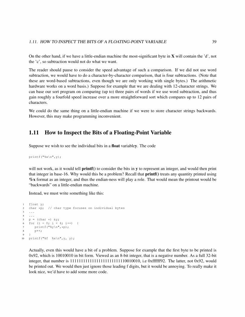
1.11. HOW TO INSPECT THE BITS OF A FLOATING-POINT VARIABLE 39
On the other hand, if we have a little-endian machine the most-significant byte in X will contain the ’d’, notthe ’c’, so subtraction would not do what we want.
The reader should pause to consider the speed advantage of such a comparison. If we did not use wordsubtraction, we would have to do a character-by-character comparison, that is four subtractions. (Note thatthese are word-based subtractions, even though we are only working with single bytes.) The arithmetichardware works on a word basis.) Suppose for example that we are dealing with 12-character strings. Wecan base our sort program on comparing (up to) three pairs of words if we use word subtraction, and thusgain roughly a fourfold speed increase over a more straightforward sort which compares up to 12 pairs ofcharacters.
We could do the same thing on a little-endian machine if we were to store character strings backwards.However, this may make programming inconvenient.
1.11 How to Inspect the Bits of a Floating-Point Variable
Suppose we wish to see the individual bits in a float variabley. The code
printf("%x\n",y);
will not work, as it would tell printf() to consider the bits in y to represent an integer, and would then printthat integer in base-16. Why would this be a problem? Recall that printf() treats any quantity printed using%x format as an integer, and thus the endian-ness will play a role. That would mean the printout would be“backwards” on a little-endian machine.
Instead, we must write something like this:
1 float y;2 char *p; // char type focuses on individual bytes3 ...4 ...5 p = (char *) &y;6 for (i = 0; i < 4; i++) {7 printf("%y\n",*p);8 p++;9 }
10 printf("%f %x\n",y, y);
Actually, even this would have a bit of a problem. Suppose for example that the first byte to be printed is0x92, which is 10010010 in bit form. Viewed as an 8-bit integer, that is a negative number. As a full 32-bitinteger, that number is 11111111111111111111111110010010, i.e 0xffffff92. The latter, not 0x92, wouldbe printed out. We would then just ignore those leading f digits, but it would be annoying. To really make itlook nice, we’d have to add some more code.

40 CHAPTER 1. INFORMATION REPRESENTATION AND STORAGE

Chapter 2
Major Components of Computer “Engines”
2.1 Introduction
Recall from Chapter 0 that we discussed the metaphor of the “engine” of a computer. This engine has twomain components:
• the hardware, including the central processing unit (CPU) which executes the computer’s machinelanguage, and
• the low-level software, consisting of various services that the operating system makes available toprograms.
This chapter will present a broad overview of both components of this engine. The details will then unfoldin the succeeding chapters.
One of the major goals of this chapter, and a frequent theme in the following chapters, is to develop anunderstanding of the functions of these two components. In particular, questions which will be addressedboth in this chapter and in the chapters which follow concern the various functions of computer systems:
• What functions are typically implemented in hardware?
• What functions are typically implemented in software?
• For which functions are both hardware and software implementations common? Why is hardwareimplementation generally faster, but software implementation more flexible?
41

42 CHAPTER 2. MAJOR COMPONENTS OF COMPUTER “ENGINES”
Figure 2.1: system structure
Related to these questions are the following points, concerning the portability of a program, i.e. the abilityto move a program developed under one computing environment to another. What dependencies, if any,does the program have to that original environment? Potential dependencies are:
• Hardware dependencies:
A program written in machine language for an older PC’s Intel 80386 CPU1 certainly won’t run onMotorola’s PowerPC CPU.2 But that same program will run on PC using the Intel Pentium, since theIntel family is designed to be upward compatible, meaning that programs written for earlier membersof the Intel CPU family are guaranteed to run on later members of the family (though not vice versa).
• Operating system (OS) dependencies:
A program written to work on a PC under the Windows OS will probably not run on the same machineunder the Linux OS (and vice versa), since the program will probably call OS functions.
And finally, we will discuss one of the most important questions of all: What aspects of the hardwareand software components of the engine determine the overall speed at which the system will run a givenprogram?
2.2 Major Hardware Components of the Engine
2.2.1 System Components
A block diagram of the basic setup of a typical computer system appears in Figure 2.1.
The major components are as follows:
CPU1Or clones of Intel chips, such as those by AMD. Throughout this section, our term Intel will include the clones.2This is what the Apple Macintosh used until 2005.

2.2. MAJOR HARDWARE COMPONENTS OF THE ENGINE 43
As mentioned earlier, this is the central processing unit, often called simply the processor, where the actualexecution of a program takes place. (Since only machine language programs can execute on a computer, theword program will usually mean a machine language program. Recall that we might write such a programdirectly, or it might be produced indirectly, as the result of compiling a source program written in a high-levellanguage (HLL) such as C.)
Memory
A program’s data and machine instructions are stored here during the time the program is executing. Mem-ory consists of cells called words, each of which is identifiable by its address.
If the CPU fetches the contents of some word of memory, we say that the CPU reads that word. On theother hand, if the CPU stores a value into some word of memory, we say that it writes to that word. Readingis analogous to watching a video cassette tape, while writing is analogous to recording onto the tape.
Ordinary memory is called RAM, for Random Access Memory, a term which means that the access timeis the same for each word.3 There is also ROM (Read-Only Memory), which as its name implies, can beread but not written. ROM is used for programs which need to be stored permanently in main memory,staying there even after the power is turned off. For example, an autofocus camera typically has a com-puter in it, which runs only one program, a program to control the operation of the camera. Think of howinconvenient—to say the least—it would be if this program had to be loaded from a disk drive everytimeyou took a picture! It is much better to keep the program in ROM.4
I/O Devices
A typical computer system will have several input/output devices, possibly even hundreds of them (Figure2.1 shows two of them). Typical examples are keyboards/monitor screens, floppy and fixed disks, CD-ROMs, modems, printers, mice and so on.
Specialized applications may have their own special I/O devices. For example, consider a vending machine,say for tickets for a regional railway system such as the San Franciso Bay Area’s BART, which is capable ofaccepting dollar bills. The machine is likely to be controlled by a small computer. One of its input devicesmight be an optical sensor which senses the presence of a bill, and collects data which will be used to analyzewhether the bill is genuine. One of the system’s output devices will control a motor which is used to pull inthe bill; a similar device will control a motor to dispense the railway ticket. Yet another output device willbe a screen to give messages to the person buying the ticket, such as “please deposit 25 cents more.”
The common feature of all of these examples is that they serve as interfaces between the computer andthe “outside world.” Note that in all cases, they are communicating with a program which is running on
3 In the market for personal computers, somehow the word “memory” has evolved to mean disk space, quite different from theusage here. In that realm, what we refer to here as “memory” is called “RAM.” The terms used in this book are the original ones,and are standard in the computer industry, for instance among programmers and computer hardware designers. However, the readershould keep in mind that the terms are used differently in some other contexts.
4Do not confuse ROM with CD-ROMs, in spite of the similar names. A ROM is a series of words with addresses within thecomputer’s memory space, just like RAM, whereas a CD-ROM is an input/output device, like a keyboard or disk.

44 CHAPTER 2. MAJOR COMPONENTS OF COMPUTER “ENGINES”
the computer. Just as you have in the past written programs which input from a keyboard and output to amonitor screen, programs also need to be written in specialized applications to do input/output from specialI/O devices, such as the railway ticket machine application above. For example, the optical sensor wouldcollect data about the bill, which would be input by the program. The program would then analyze this datato verify that the bill is genuine.
Note carefully the difference between memory and disk.5 Memory is purely electronic, while disk is elec-tromechanical, the latter referring to the fact that a disk is a rotating platter. Both memory and disk storebits, but because of the mechanical nature of disk, it is very much slower than memory—memory access ismeasured in nanoseconds (billionths of seconds) while disk access is measured in milliseconds (thousandthsof seconds). The good thing about disk is that it is nonvolatile, so we can store files permanently.6 Also,disk storage is a lot cheaper, per bit stored, than memory.
System Bus
A bus is a set of parallel wires (usually referred to as “lines”), used as communication between components.Our system bus plays this role in Figure 2.1— he CPU communicates with memory and I/O devices viathe bus. It is also possible for I/O devices to communicate directly with memory, an action which is calleddirect memory access (DMA), and again this is done through the bus.7
The bus is broken down into three sub-buses:
• Data Bus:
As its name implies, this is used for sending data. When the CPU reads a memory word, the memorysends the contents of that word along the data bus to the CPU; when the CPU writes a value to amemory word, the value flows along the data bus in the opposite direction.
Since the word is the basic unit of memory, a data bus usually has as many lines as there are bits in amemory word. For instance, a machine with 32-bit word size would have a data bus consisting of 32lines.
• Address Bus:
When the CPU wants to read or write a certain word of memory, it needs to have some mechanismwith which to tell memory which word it wants to read or write. This is the role of the address bus.For example, if the CPU wants to read Word 504 of memory, it will put the value 504 on the addressbus, along which it will flow to the memory, thus informing memory that Word 504 is the word theCPU wants.
5Often confused by the fact that salespeople at computer stores erroneously call disk “memory.”6We couldn’t do that with ROM, since we want to be able to modify the files.7This is the basic view, but technically it applies more to older or smaller computers. In a PC, for instance, there will be extra
chips which serve as “agents” for the CPU’s requests to memory. For a description of how some common chips like this work, andtheir implications for software execution speed, see Chapter 5 of Code Optimization: Effective Memory Usage, by Kris Kaspersky,A-LIST, 2003.

2.2. MAJOR HARDWARE COMPONENTS OF THE ENGINE 45
The address bus usually has the same number of lines as there are bits in the computer’s addresses.
• Control Bus:
How will the memory know whether the CPU wants to read or write? This is one of the functionsof the control bus. For example, the control bus in typical PCs includes lines named MEMR andMEMW, for “memory read” and “memory write.” If the CPU wants to read memory, it will assertthe MEMR line, by putting a low voltage on it, while for a write, it will assert MEMW. Again, thissignal will be noticed by the memory, since it too is connected to the control bus, and so it can actaccordingly.
As an example, consider a machine with both address and word size equal to 32 bits. Let us denote the32 lines in the address bus as A31 through A0, corresponding to Bits 31 through 0 of the 32-bit address,and denote the 32 lines in the data bus by D31 through D0, corresponding to Bits 31 through 0 of the wordbeing accessed. Suppose the CPU executes an instruction to fetch the contents of Word 0x000d0126 ofmemory. This will involve the CPU putting the value 0x000d0126 onto the address bus. Remember, this ishex notation, which is just a shorthand abbreviation for the actual value,
000000000000000011010000000100100110
So, the CPU will put 0s on lines A31 through A20, a 1 on Line A19, a 1 on Line A18, a 0 on Line A17, andso on. At the same time, it will assert the MEMR line in the control bus. The memory, which is attachedto these bus lines, will sense these values, and “understand” that we wish to read Word 0x000d0126. Thusthe memory will send back the contents of that word on the data bus. If for instance c(0x000d0126) = 0003,then the memory will put 0s on Lines D31 through D2, and 1s on Lines D1 and D0, all of which will besensed by the CPU.
Some computers have several buses, thus enabling more than one bus transaction at a time, improvingperformance.
2.2.2 CPU Components
2.2.2.1 Intel/Generic Components
We will now look in more detail at the components in a CPU. Figure 2.2 shows the components that makeup a typical CPU. Included are an arithmetic and logic unit (ALU), and various registers.
The ALU, as its name implies, does arithmetic operations, such as addition, subtraction, multiplication anddivision, and also several logical operations. The latter category of operations are similar to the &&, || and! operators in the C language) used in logical expressions such as

46 CHAPTER 2. MAJOR COMPONENTS OF COMPUTER “ENGINES”
Figure 2.2: CPU internals
if (a < b && c == 3) x = y;
The ALU does not store anything. Values are input to the ALU, and results are then output from it, but itdoes not store anything, in contrast to memory words, which do store values. An analogy might be madeto telephone equipment. A telephone inputs sound, in the form of mechanical vibrations in the air, andconverts the sounds to electrical pulses to be sent to the listener’s phone, but it does not store these sounds.A telephone tape-recording answering machine, on the other hand, does store the sounds which are input toit.
Registers are storage cells similar in function to memory words. The number of bits in a register is typicallythe same as that for memory words. We will even use the same c( ) notation for the contents of a register aswe have used for the contents of a memory word. For example, c(PC) will denote the contents of the registerPC described below, just as, for instance, c(0x22c4) means the contents of memory word 0x22c4. Keep inmind, though, that registers are not in memory; they are inside the CPU. Here are some details concerningthe registers shown in Figure 2.2.
• PC: This is the program counter. Recall that a program’s machine instructions must be stored inmemory while the program is executing. The PC contains the address of the currently executinginstruction. The term PC is a generic term; on Intel, the register is called EIP (Extended InstructionPointer).

2.2. MAJOR HARDWARE COMPONENTS OF THE ENGINE 47
• ESP: The stack pointer contains the address of the “top” of a certain memory region which is calledthe stack. A stack is a type of data structure which the machine uses to keep track of function callsand other information, as we will see in Chapter 5.
• EAX, EBX, etc.: These are data registers, used for temporary storage of data.
• EFLAGS: The processor status register (PS), called EFLAGS on Intel machines, contains miscel-laneous pieces of information, including the condition codes. The latter are indicators of informationsuch as whether the most recent computation produced a negative, positive or zero result. Note thatthere are wires leading out of the ALU to the EFLAGS (shown as just one line in Figure 2.2). Theselines keep the condition codes up to date. Each time the ALU is used, the condition codes are imme-diately updated according to the results of the ALU operation.
Generally the PS will contain other information in addition to condition codes. For example, it wasmentioned in MIPS and PowerPC processors give the operating system a choice as to whether themachine will run in big-endian or little-endian mode. A bit in the PS will record which mode is used.
• MAR: The memory address register is used as the CPU’s connection to the address bus. For exam-ple, if the currently executing instruction needs to read Word 0x0054 from memory, the CPU will put0x0054 into MAR, from which it will flow onto the address bus.
• MDR: The memory data register is used as the CPU’s connection to the data bus. For example, ifthe currently executing instruction needs to read Word 0x0054 from memory, the memory will putc(0x0054) onto the data bus, from which it will flow into the MDR in the CPU. On the other hand, ifwe are writing to Word 0x0054, say writing the value 0x0019, the CPU will put 0x0019 in the MDR,from which it will flow out onto the data bus and then to memory. At the same time, we will put0x0054 into the MAR, so that the memory will know to which word the 0x0019 is to be written.
• IR: This is the instruction register. When the CPU is ready to start execution of a new instruction,it fetches the instruction from memory. The instruction is returned along the data bus, and thus isdeposited in the MDR. The CPU needs to use the MDR for further accesses to memory, so it enablesthis by copying the fetched instruction into the IR, so that the original copy in the MDR may beoverwritten.
A note on the sizes of the various registers: The PC, ESP, and MAR all contain addresses, and thus typicallyhave sizes equal to the address size of the machine. Similarly, the MDR typically has sizes equal to the wordsize of the machine. The PS stores miscellaneous information, and thus its size has no particular relation tothe machine’s address or word size. The IR must be large enough to store the longest possible instructionfor that machine.
A CPU also has internal buses, similar in function to the system bus, which serve as pathways with whichtransfers of data from one register to another can be made. Figure 2.2 shows a CPU having only one suchbus, but some CPUs have two or more. Internal buses are beyond the scope of this book, and thus anyreference to a “bus” from this point onward will mean the system bus.

48 CHAPTER 2. MAJOR COMPONENTS OF COMPUTER “ENGINES”
The reader should pay particular attention to the MAR and MDR. They will be referred to at a number ofpoints in the following chapters, both in text and in the exercises—not because they are so vital in their ownright, but rather because they serve as excellent vehicles for clarifying various concepts that we will coverin this book. In particular, phrasing some discussions in terms of the MAR and MDR will clarify the factthat some CPU instructions access memory while others do not.
Again, the CPU structure shown above should only be considered “typical,” and there are many variations.RISC CPUs, not surprisingly, tend to be somewhat simpler than the above model, though still similar.
2.2.2.2 History of Intel CPU Structure
The earliest widely-used Intel processor chip was the 8080. Its word size was 8 bits, and it included registersnamed A, B, C and D (and a couple of others). Address size was 16 bits.
The next series of Intel chips, the 8086/8088,8 and then the 80286, featured 16-bit words and 20-bit ad-dresses. The A, B, C and D registers were accordingly extended to 16-bit size and renamed AX, BX, CXand DX (‘X’ stood for “extended”). Other miscellaneous registers were added. The lower byte of AX wascalled AL, the higher byte AH, and similarly for BL, BH, etc.
Beginning with the 80386 and extending to the Pentium series, both word and address size were 32 bits. Theregisters were again extended in size, to 32 bits, and renamed EAX, EBX and so on (‘E’ for “extended”).The 64-bit generation is now commonplace.
The pre-32-bit Intel CPUs, starting with 8086/8088, replaced the single register PC with a pair of registers,CS (for code segment) and IP (for instruction pointer). A rough description is that the CS register pointed tothe code segment, which is the place in memory where the program’s instructions start, and the IP registerthen specified the distance in bytes from that starting point to the current instruction. Thus by combiningthe information given in c(CS) and c(IP), we obtained the absolute address of the current instruction.
This is still true today when an Intel CPU runs in 16-bit mode, in which case it generates 20-bit addresses.The CS register is only 16 bits, but it represents a 20-bit address whose least significant four bits are implic-itly 0s. (This implies that code segments are allowed to begin only at addresses which are multiples of 16.)The CPU generates the address of the current instruction by concatenating c(CS) with four 0 bits9 and thenadding the result to c(IP).
Suppose for example the current instruction is located at 0x21082, and the code segment begins at 0x21040.Then c(CS) and c(IP) will be 0x2104 and 0x0042, respectively, and when the instruction is to be executed,its address will be generated by combining these two values as shown above.
The situation is similar for stacks and data. For example, instead of having a single SP register as in ourmodel of a typical CPU above, the earlier Intel CPUs (and current CPUs when they are running in 16-bit
8The first IBM PC used the 8088.9This is one 0 hex digit. Note too that this concatenation is equivalent to multiplying by 16.

2.2. MAJOR HARDWARE COMPONENTS OF THE ENGINE 49
mode) use a pair of registers, SS and SP. SS specifies the start of the stack segment, and SP contains thedistance from there to the current top-of-stack. For data, the DS register points to the start of the datasegment, and a 16-bit value contained in the instruction specifies the distance from there to the desired dataitem.
Since IP, SP and the data-item distance specified within an instruction are all 16-bit quantities, it followsthat the code, stack and data segments are limited to 216 = 65, 536 bytes in size. This can make things quiteinconvenient for the programmer. If, for instance, we have an array of length, say, 100,000 bytes, we couldnot fit the array into one data segment. We would need two such segments, and the programmer would haveto include in the program lines of code which change the value of c(DS) whenever it needs to access a partof the array in the other data segment.
These problems are avoided by the newer operating systems which run on Intel machines today, such asWindows and Linux, since they run in 32-bit mode. Addresses are also of size 32 bits in that mode, and IP,SP and data-item distance are 32 bits as well. Thus a code segment, for instance, can fill all of memory, andsegment switching as illustrated above is unnecessary.
This continues to be the case for 64-bit machines, e.g. with 64-bit addresses.
2.2.3 The CPU Fetch/Execute Cycle
After its power is turned on, the typical CPU pictured in Figure 2.2 will enter its fetch/execute cycle,repeatedly cycling through these three steps, i.e. Step A, Step B, Step C, Step A, Step B, and so on:
• Step A: The CPU will perform a memory read operation, to fetch the current instruction. This involvescopying the contents of the PC to the MAR, asserting a memory-read line in the control bus, and thenwaiting for the memory to send back the requested instruction along the data bus to the MDR. Whilewaiting, the CPU will update the PC, to point to the following instruction in memory, in preparationfor Step A in the next cycle.
• Step B: The CPU will copy the contents of MDR to IR, so as to free the MDR for further memoryaccesses. The CPU will inspect the instruction in the IR, and decode it, i.e. decide what kind ofoperation this instruction performs—addition, subtraction, jump, and so on.
• Step C: Here the actual execution of the operation specified by the instruction will be carried out.If any of the operands required by the instruction are in memory, they will be fetched at this time,by putting their addresses into MAR and waiting for them to arrive at MDR. Also, if this instructionstores its result back to memory, this will be accomplished by putting the result in MDR, and puttinginto MAR the memory address of the word we wish to write to.
After Step C is done, the next cycle is started, i.e. another Step A, then another Step B, and so on. Again,keep in mind that the CPU will continually cycle through these three steps as long as the power remains

50 CHAPTER 2. MAJOR COMPONENTS OF COMPUTER “ENGINES”
on. Note that all of the actions in these steps are functions of the hardware; the circuitry is designed totake these actions, while the programmer merely takes advantage of that circuitry, by choosing the propermachine instructions for his/her program.
A more detailed description of CPU operations would involve specifying its microsteps. These are beyondthe scope of this book, and the three-step cycle described above will give sufficient detail for our purposes,though we will use them later to illustrate the term clock speed.
2.3 Software Components of the Computer “Engine”
There are many aspects of a computer system which people who are at the learning stage typically take forgranted as being controlled by hardware, but which are actually controlled by software. An example of thisis the backspace action when you type the backspace key on the keyboard. You are accustomed to seeingthe last character you typed now disapppear from the screen, and the cursor moving one position to the left.You might have had the impression that this is an inherent property of the keyboard and the screen, i.e. thattheir circuitry was designed to do this. However, for most computer systems today this is not the case. Thebare hardware will not take any special action when you hit the backspace key. Instead, the special action istaken by whichever operating system (OS) is being used on the computer.
The OS is software—a program, which a person or group of people wrote to provide various services to userprograms. One of those services is to monitor keystrokes for the backspace key, and to take special actions(move the cursor leftward one position, and put a blank where it used to be) when encountering that key.When you write a program, say in C, you do not have to do this monitoring yourself, which is a tremendousconvenience. Imagine what a nuisance it would be if you were forced to handle the backspace key yourself:You would have to include some statements in each program you write to check for the backspace key, andto update the screen if this character is encountered. The OS relieves you of this burden.
But if you want this “burden”—say you are writing a game or a text editor and need to have characters readas they are typed, instead of waiting for the user to hit the Enter key—then the OS also will turn off thebackspace, echo etc. if you request it. In UNIX, this is done via the ioctl() system call.
This backspace-processing is an example of one of the many services that an OS provides. Another exampleis maintenance of a file system. Again the theme is convenience. When you create a file, you do not haveto burden yourself with knowing the physical location of your file on the disk. You merely give the file aname. The OS finds unused space on the disk to store your file, and enters the name and physical location ina table that the OS maintains. Subsequently, you may access the file merely by specifying the name, and theOS service will translate that into the physical location and access the file on your behalf. In fact, a typicalOS will offer a large variety of services for accessing files.
So, a user program will make use of many OS services, usually by calling them as functions. For example,consider the C-language function scanf(). Though of course you did not write this function yourself, some-

2.4. SPEED OF A COMPUTER “ENGINE” 51
one did, and and in doing so that person (or group of people) relied heavily on calls to an OS subroutine,read(). In terms of our “look under the hood” theme, we might phrase this by saying that a look under thehood of the C scanf() source code would reveal system calls to the OS function read(). For this reason, theOS is often referred to as “low-level” software. Also, this reliance of user programs on OS services showswhy the OS is included in our “computer engine” metaphor—the OS is indeed one of the sources of “power”for user programs, just as the hardware is the other source of power.
To underscore that the OS services do form a vital part of the computer’s “engine,” consider the followingexample. Suppose we have a machine-language program—which we either wrote ourselves or produced bycompiling from C—for a DEC computer with a MIPS CPU. Could that program be run without modificationon a Silicon Graphics machine, which also uses the MIPS chip? The answer is no. Even though bothmachines do run a Unix OS, there are many different “flavors” of Unix. The DEC version of Unix, calledUltrix, differs somewhat from the SGI version, called IRIX. The program in question would probably includea number of calls to OS services—recall from above that even reads from the keyboard and writes to thescreen are implemented as OS services—and those services would be different under the two OSs.
Thus even though individual instructions of the program written for the DEC would make sense on the SGImachine, since both machines would use the same type of CPU, some of those instructions would be devotedto OS calls, which would differ.
Since an OS consists of a program, written to provide a group of services, it follows that several differentOSs—i.e. several different programs which offer different groups of services—could be run on the samehardware. For instance, this is the case for PCs. The most widely used OS for these CPUs is MicrosoftWindows, but there are also several versions of Unix for PCs, notably the free, public-domain Linux and thecommercial SCO.
2.4 Speed of a Computer “Engine”
What factors determine the speed capability of a computer engine? This is an extremely complex questionwhich is still a subject of hot debate in both academia and the computer industry. However, a number offactors are clear, and will be introduced here. The presentation below will just consist of overviews, and theinterested reader should pursue further details in books on computer architecture and design. However, it isimportant that the reader get some understanding of the main issues now; at the very least enough to be ableto understand newspaper PC ads! The discussion below is aimed at that goal.
2.4.1 CPU Architecture
Different CPU types have different instruction and register sets. The Intel family, for example, has a verynice set of character-string manipulation instructions, so it does such operations especially quickly. This iscounterbalanced somewhat by the fact that CPUs in this family have fewer registers than do CPUs in some

52 CHAPTER 2. MAJOR COMPONENTS OF COMPUTER “ENGINES”
other families, such as those in most of the newer machines.10 Since registers serve as local—and thusfast—memory, the more of them we have, the better, and thus the Intel family might be at a disadvantage inthis respect.
2.4.2 Parallel Operations
One way to get more computing done per unit time is do several things at one time, i.e. in parallel. Mostmodern machines, even inexpensive ones such as personal computers, include some forms of parallelism.
For example, most CPUs perform instruction prefetch: During execution of the current instruction, theCPU will attempt to fetch one or more of the instructions which follow it sequentially—i.e. at increasingaddresses—in memory.11 For example, consider an Intel chip running in 16-bit mode. In this mode thechip has 20-bit addresses. Consider a two-byte instruction at location 0x21082. During the time we areexecuting that instruction the CPU might attempt to start fetching the next instruction, at 0x21084. Thesuccess or failure of this attempt will depend on the duration of the instruction at 0x21082. If this attemptis successful, then Step A can be skipped in the next cycle, i.e. the instruction at 0x21084 can be executedearlier.
Of course, the last statement holds only if we actually do end up executing the instruction at 0x21084. If theinstruction at 0x21082 turns out to be a jump instruction, which moves us to some other place in memory, wewill not execute the instruction at 0x21084 at all. In this case, the prefetching of this instruction during theexecution of the one at 0x21082 would turn out to be wasted. Modern CPUs have elaborate jump-predictionmechanisms to try to deal with this problem.
Intel CPUs will often fetch several downstream instructions, while for RISC CPUs we might be able to fetchonly one. The reason for this is that RISC instructions, being so simple, have such short duration that therejust is not enough time to fetch more than one instruction.
Instruction prefetching is a special case of a more general form of parallelism, called pipelining. Thisconcept treats the actions of an instruction as being like those of an assembly line in a factory. Consider anautomobile factory, for instance. Its operation is highly parallel, which the construction of many cars beingdone simultaneously. At any given time, one car, at any early stage in the assembly line, might be having itsengine installed, while another car, at a later stage in the line, is having its transmission installed. PipelinedCPUs (which includes virtually every modern CPU) break instruction execution down into several stages,and have several instructions executing at the same time, in different stages. In the simple case of instructionprefetch, there would be only two stages, one for the fetch (Step A) and the other for execution (Steps B andC).
Most recently-designed CPUs are superscalar, meaning that a CPU will have several ALUs. This is another
10 This does not include the newer Intel chips, such as the Pentium, because these chips had to be designed for compatibility withthe older ones.
11 The prefetch may insted be from the cache, which we will discuss later.

2.4. SPEED OF A COMPUTER “ENGINE” 53
way in which we can get more than one instruction executing at a time.
Yet another way to do this is to have multiple CPUs! In multiprocessor systems with n CPUs, we canexecute n instructions at once, instead of one, thus potentially improving system speed by a factor of n.Typical speedup factors in real applications are usually much less than n, due to such overhead as the needfor the several CPUs to coordinate actions with each other, and not get in each other’s way as they accessmemory.
The classical way of constructing multiprocessor systems was to connect several CPUs to the system bus.However, as of 2006, it is common for even many low-end CPU chips to be dual core, meaning that thechip actually contains two CPUs. This has brought multiprocessor computing into the home.
It used to be very expensive to own a multiprocessor machine. The CPUs would all be connected to thebus, which increases manufacturing costs, etc. But by having more than once CPU on a chip, the expense issmall.
Note that chip manufacturers have found that it makes better economic sense now for them to use chip spacefor extra processors, rather than continuing to increase processor speed.
2.4.3 Clock Rate
Recall that each machine instruction is implemented as a series of microsteps. Each microstep has the sameduration, namely one clock cycle, which is typically set as the time needed to transfer a value from one CPUregister to another. The CPU is paced by a CPU clock, a crystal oscillator; each pulse of the clock triggersone microstep.
In 2002, clock rates of over 1 gigahertz, i.e. 1 billion cycles per second, became common in PCs. This isquite a contrast to the 4.77 megahertz clock speed of the first IBM PC, introduced in 1981.
Each instruction takes a certain number of clock cycles. For example, an addition instruction with bothoperands in CPU registers might take 2 clock cycles on a given CISC CPU, while a multiply instructionwith these operands takes 21 clock cyles on the same CPU. If one of the operands is in memory, the timeneeded will increase beyond these values.
RISC machines, due to the fact that they perform only simple operations (and usually involving only regis-ters), tend to have instructions which operate in a single clock cylce.
The time to execute a given instruction will be highly affected by clock rate, even among CPUs of the sametype. For example, as mentioned above, a register-to-register addition instruction might typically take 2microsteps on a CISC CPU. Suppose the clock rate is 1 gigahertz, so that a clock cycle takes 10−9 seconds,i.e. 1 nanosecond.12 Then the instruction would take 2 nanoseconds to execute.
12A nanosecond is a billionth of a second.

54 CHAPTER 2. MAJOR COMPONENTS OF COMPUTER “ENGINES”
Within a CPU family, say the Intel family, the later members of the family typically run a given programmuch faster than the earlier members, for two reasons related to clock cycles:
• Due to advances in fabrication of electronic circuitry, later members of a CPU family tend to havemuch faster clock rates than do the earlier ones.
• Due to more clever algorithms, pipelining, and so on, the later members of the family often canaccomplish the same operation in fewer microsteps than can the earlier ones.
2.4.4 Memory Caches
2.4.4.1 Need for Caching
In recent years CPU speeds have been increasing at very impressive rates, but memory access speeds havenot kept pace with these increases. Remember, memory is outside the CPU, not in it. This causes slowaccess, for various reasons.
• The physical distance from the CPU is on the order of inches, whereas it is typically less than an inchwithin the CPU. Even though signals travel at roughly 2/3 the speed of light, there are so many signalssent per second that even this distance is a factor causing slowdown.
• An electrical signal propagates more slowly when it leaves a CPU chip and goes onto the bus towardmemory. This is due to the bus wires being far thicker than the very fine wires within the CPU.
• Control buses typically must include handshaking lines, in which the various components attachedto the bus assert to coordinate their actions. One component says to the other, “Are you ready,” andthat component cannot proceed until it gets a response from the other. This causes delay.
2.4.4.2 Basic Idea of a Cache
To solve these problems, a storage area, either within the CPU or near it or both, is designed to act asa memory cache. The cache functions as a temporary storage area for a copy of some small subset ofmemory, which can be accessed locally, thus avoiding a long trip to memory for the desired byte or word.13
Say for example the program currently running on the CPU had in its source file the line
char x;
13Modern computers typically have two caches, an L1 cache inside the CPU, and an L2 cache just outside it. When the CPUwants to access a byte or word, it looks in L1 first; if that fails, it looks in L2; and if that fails, it goes to memory. Here, though, wewill assume only an L1 cache.

2.4. SPEED OF A COMPUTER “ENGINE” 55
and suppose that x is stored in byte 1205 of memory, i.e. &x is 1205. Consider what occurs in eachinstruction in the program that reads x. Without a cache, the CPU would put 1205 on the address bus, andassert the MEMR line in the control bus. The memory would see these things on the bus, and copy whateveris in location 1205 to the data bus, from which the CPU would receive it.
If we did have a cache, the CPU would look first to see if the cache contains a copy of location 1205. If so,the CPU does not have to access memory, a huge time savings. This is called a cache hit. If the CPU doesnot find that the cache contains a copy of location 1205—a cache miss—then the CPU must go to memoryin the normal manner.
2.4.4.3 Blocks and Lines
Memory is partitioned into blocks, of fixed size. For concreteness, we will assume here that the blocksize is 512 bytes. Then Bytes 00000-000511 form Block 0, Bytes 00512-001023 form Block 1, and soon. A memory byte’s block number is therefore its address divided by the block size. Equivalently, sincelog2512 = 9, if our address size is 32 bits, then the location’s block number is given in the most-significant23 bits of the address, i.e. all the bits of the address except for the lower 9. The lower 9 bits then givelocation of the byte within the block.14 Note that the partitioning is just conceptual; there is no “fence” orany other physical boundary separating one block from another.
This organization by blocks comes into play in the following manner. Consider our example above in whichthe CPU wanted to read location 1205. The block number is b1205/512c = 2. The CPU would not reallysearch the cache for a copy of byte 1205 or even word 1205. Instead, the CPU would search for a copy ofthe entire block containing location 1205, i.e. a copy of block 2.
The cache is partitioned into a fixed number of slots, called lines. Each slot has room for a copy of oneblock of memory, plus an extra word in which additional information is stored. This information includes atag, which states which block has a copy in memory right now. This is vital, of course, as otherwise whenthe CPU looked in the cache, it wouldn’t know whether this line contains a copy of the desired block, asopposed to a copy of some other block.
At any given time, the cache contains copies of some blocks from memory, with different blocks beinginvolved at different times. For example, suppose again the CPU needs to read location 1205. It thensearches the cache for a copy of block 2. In each line in which it searches, the CPU would check the tagfor that line. If the tag says “This line contains a copy of block 2,” then the CPU would see that this is ahit. The CPU would then get byte 1205 from this line as follows. As we saw above, byte 1205 is in blockb1205/512c = 2, and using the same reasoning,15 within that block, this byte is byte number 1205 mod 512
14 Suppose we have 10 classrooms, each with 10 kids, sitting in 10 numbered seats, according to the kids’ ID numbers. Kids 0-9are in classroom 0, 10-19 are in classroom 1, and so on. So for instance kid number 28 will be in classroom 2, sitting in seat 8 ofthat room. Note how the 2 comes from the upper 1 digit of the ID number, and the 8 comes from the lower 1 digit—just like theblock number of a byte is given by the upper 23 bits in the address, while the byte number within block is given by the lower 9 bits.
15Recall note 14. Make SURE you understand this point.

56 CHAPTER 2. MAJOR COMPONENTS OF COMPUTER “ENGINES”
= 181. So, the CPU would simply look at the 181st byte in this line.16
If on the other hand, the CPU finds that block 2 does not have a copy in the cache, the CPU will read theentire block 2 from memory, and put it into some cache line. It may have to remove a copy of some otherblock in doing so; the term used for this is that that latter block copy is evicted.
The total number of lines varies with the computer; the number could be as large as the thousands, or on theother extreme less than ten. The larger the cache, the higher the hit rate. On the other hand, bigger cachesare slower, take up too much space on a CPU chip in the case of on-chip caches, and are more expensive inthe case of off-chip caches.
2.4.4.4 Direct-Mapped Policy
One question is which lines the CPU should search in checking whether the desired block has a copy in thecache. In a fully-associative cache, the CPU must inspect all lines. This gives maximum flexibility, but ifit is large then it is expensive to implement and the search action is slower, due to the overhead of complexcircuitry.
The other extreme is called direct-mapped.17 Here the CPU needs to look in only one cache line. Bydesign, the desired block copy will either be in that particular line or not in any line at all. The number of theparticular line to be checked is the block number mod the number of lines. Let us suppose for illustrationthat there are 32 lines in the cache. In our example above, byte 1205 was in block 2, and since 2 mod 32 =2, then to check whether block 2 has a copy in the cache, the CPU needs to look only at line 2. If the tag inline 2 says “This is a copy of block 2,” then the CPU sees we have a hit. If not, the CPU knows it is a miss.The basic design of this direct-mapped cache is that a copy of block 2 will either be in the cache at line 2 orelse the block will not have a copy in the cache at all.
Now suppose after successfully reading byte 1205, at some time later in the execution of this program weneed to read byte 17589. This is block b17589/512c = 34. Since 34 mod 32 = 2, the CPU will again look atline 2 in the cache. But the tag there will say that this line currently contains a copy of block 2. Thus therewill be a miss. The CPU will bring in a copy of block 34, which will replace the copy of block 2, and thetag will be updated accordingly.
2.4.4.5 What About Writes?
One issue to be resolved is what to do when we have a cache hit which is a write. The issue is that now thecopy of the block in the cache will be different from the “real” block in memory. Eventually the two mustbe made consistent, but when? There are two main types of policies:
16This means the block begins with its “0th” byte.17A compromise scheme, called set-associative, is very common.

2.4. SPEED OF A COMPUTER “ENGINE” 57
• Under a write-through policy, any write to the cache would also be accompanied by an immediatecorresponding write to memory.
• Under a write-back policy, we do not make the memory block consistent with its cache copy untilthe latter is evicted. At that time, the entire block is written to memory.
Which policy is better will depend on the program being run. Suppose for example we only write to a cacheline once before it is evicted. Then write-back would be rather disastrous, since the entire block would bewritten to memory even though the inconsistency consists of only one byte or word. On the other hand, incode such as
for (i = 0; i < 10000; i++)sum += x[i];
if sum is the only part of its cache line being used, we only care about the final value of sum, so updating itto memory 10,000 times under a write-through policy would be highly inefficient.
2.4.4.6 Programmability
As noted in Section 2.4.4.5, the behavior of a particular write policy depends on which program is beingrun. For this reason, many CPUs, e.g. the Pentium, give the programmer the ability to have some blockssubject to a write-through policy and others subject to write-back.
Similarly, the programmer may declare certain blocks not cacheable at all. The programmer may do this, forexample, if the programmer can see that this block would have very poor cache behavior. Another reasonfor designating a block as noncacheable is if the block is also being accessed by a DMA device.
2.4.4.7 Details on the Tag and Misc. Line Information
Consider line 2 in the cache. We will search that line if the number of the block we want is equal to 2, mod32. That means that the tag, which states the number of the block copy stored in this line, must have 00010as its last 5 bits. In view of that, it would be wasteful to store those bits. So, we design the tag to consistonly of the remainder of the block number, i.e. the upper 18 bits of the block number.
Let’s look at our example 17589 above again. Recall that this is in block 34 = 00000000000000000100010.Since the last 5 bits are 00010, the CPU will examine the tag in cache line 2. The CPU will then see whetherthe tag is equal to 000000000000000001, the upper 18 bits of 34. If so, it is a hit.
At the beginning, a line might not contain any valid data at all. Thus we need another bit in the line, calledthe Valid Bit, which tells us whether there is valid data in that line (1 means valid).

58 CHAPTER 2. MAJOR COMPONENTS OF COMPUTER “ENGINES”
If a write-back policy is used, we need to know whether a given cache line has been written to. If it has, thenthe line must be copied back to memory when it is evicted, but if not, we would want to skip that step. Forthis purpose, in addition to the tag, the line maintains a Dirty Bit, “dirty” meaning “has been written to.”
Since we saved some bits in the storage of the tag, we use that space for the Valid and Dirty Bits.
2.4.4.8 Why Caches Usually Work So Well
Experience shows that most programs tend to reuse memory items repeatedly within short periods of time;for example, instructions within a program loop will be accessed repeatedly. Similarly, they tend to useitems which neighbor each other (as is true for the data accesses in Version I above), and thus they stay inthe same block for some time. This is called the principle of locality of reference, with the word “locality”meaning “nearness”—nearness in time or in space.
For these reasons, it turns out that cache misses tend to be rare. A typical hit rate is in the high 90s, say97%. This is truly remarkable in light of the fact that the size of the cache is tiny compared to the size ofmemory. Again, keep in mind that this high hit rate is due to the locality, i.e. the fact that programs tend toNOT access memory at randomly-dispersed locations.
2.4.5 Disk Caches
We note also that one of the services an OS might provide is that of a disk cache, which is a software analogof the memory caches mentioned earlier. A disk is divided into sectors, which on PCs are 512 bytes eachin size. The disk cache keeps copies of some sectors in main memory. If the program requests access to acertain disk sector, the disk cache is checked first. If that particular sector is currently present in the cache,then a time-consuming trip to the disk, which is much slower than accessing main memory, can be avoided.18
Again this is transparent to the programmer. The program makes its request to the disk-access service ofthe OS, and the OS checks the cache and if necessary performs an actual disk access. (Note therefore thatthe disk cache is implemented in software, as opposed to the memory cache, which is hardware, thoughhardware disk caches exist too.)
2.4.6 Web Caches
The same principle is used in the software for Web servers. In order to reduce network traffic, an ISP mightcache some of the more popular Web pages. Then when a request for a given page reaches the ISP, instead
18Note, though, that the access to the cache will still be somewhat slower than the access to a register. Here is why:Suppose we have 16 registers. Then the register number would be expressed as a 4-bit string, since 16 = 24. By contrast, say our
cache contains 1024 lines, which would mean that we need 10 bits to specify the line number. Digital circuity to decode a 10-bitID is slower than that for a 4-bit ID. Moreover, there would be considerable internal circuitry delays within the cache itself.

2.4. SPEED OF A COMPUTER “ENGINE” 59
of relaying it to the real server for that Web page, the ISP merely sends the user a copy. Of course, that againgives rise to an update problem; the ISP must have some way of knowing when the real Web page has beenchanged.

60 CHAPTER 2. MAJOR COMPONENTS OF COMPUTER “ENGINES”

Chapter 3
Introduction to Linux Intel AssemblyLanguage
3.1 Overview of Intel CPUs
3.1.1 Computer Organization
Computer programs execute in the computer’s central processing unit (CPU). Examples of CPUs are thePentiums in PCs and the PowerPCs in Macs.1 The program itself, consisting of both instructions and data arestored in memory (RAM) during execution. If you created the program by compiling a C/C++ source file(as opposed to writing in assembly language directly), the instructions are the machine language operations(add, subtract, copy, etc.) generated from your C/C++ code, while the data are your C/C++ variables. TheCPU must fetch instructions and data from memory (as well as store data to memory) when needed; this isdone via a bus, a set of parallel wires connecting the CPU to memory.
The components within the CPU include registers. A register consists of bits, with as many bits as the wordsize of the machine. Thus a register is similar to one word of memory, but with the key difference that aregister is inside the CPU, making it much faster to access than memory. Accordingly, when programmingin assembly language, we try to store as many of our variables as possible in registers instead of in memory.Similarly, if one invokes a compiler with an “optimize” command, the compiler will also attempt to storevariables in registers instead of in memory (and will try other speedup tricks as well).
1Slated to be replaced by Intel chips.
61

62 CHAPTER 3. INTRODUCTION TO LINUX INTEL ASSEMBLY LANGUAGE
3.1.2 CPU Architecture
There are many different different types of CPU chips. The most commonly-known to the public is the IntelPentium, but other very common ones are the PowerPC chip used in Macintosh computers and IBM UNIXworkstations, the MIPS chip used in SGI workstations and so on.
We speak of the architecture of a CPU. This means its instruction set and registers, the latter being units ofbit storage similar memory words but inside the CPU.
It is highly important that you keep at the forefront of your mind that the term machine language doesnot connote “yet another programming language” like C or C++; instead, it refers to code consisting ofinstructions for a specific CPU type. A program in Intel machine language will be rejected as nonsense ifone attempts to run it on, say, a MIPS machine. For instance, on Intel machines, 0111010111111000 meansto jump back 8 bytes, while on MIPS it would either mean something completely different or would meannothing at all.
3.1.3 The Intel Architecture
Intel CPUs can run in several different modes. On Linux the CPU runs in protected, flat 32-bit mode, orthe same for 64 bits on machines with such CPUs. For our purposes here, we will not need to define theterms protected and flat, but do keep in mind that in this mode word size is 32 bits.
For convenience, we will assume from this point onward that we are discussing 32-bit CPUs.
Intel instructions are of variable length. Some are only one byte long, some two bytes and so on.
The main registers of interest to us here are named EAX, EBX, ECX, EDX, ESI, EDI, EBP and ESP.2
These are all 32-bit registers, but the registers EAX through EDX are also accessible in smaller portions.The less-significant 16 bit portion of EAX is called AX, and the high and low 8 bits of AX are called AHand AL, respectively. Similar statements hold for EBX, ECX and EDX.
Note that EBP and ESP may not be appropriate for general use in a given program. In particular, we shouldavoid use of ESP in programs with subroutines, for reasons to be explained in Chapter 7. If we are writingsome assembly language which is to be combined with some C/C++ code, we won’t be able to use EBPeither.
Also, there is another register, the PC, which for Intel is named EIP (Extended Instruction Pointer). We cannever use it to store data, since it is used to specify which instruction is currently executing. Similarly, the
2We will use the all-caps notation, EAX, EBX, etc. to discuss registers in the text, but in program code write them as %eax,%ebx, ...
Similarly, we will use all-caps notation when referring to instruction families, such as the MOV family, even though in programcode they appear as %movl, %movb, etc.

3.2. WHAT IS ASSEMBLY LANGUAGE? 63
flags register EFLAGS, to be discussed below, is reserved as well.
3.2 What Is Assembly Language?
Machine-language is consists of long strings of 0s and 1s. Programming at that level would be extremelytedious, so the idea of assembly language was invented. Just as hex notation is a set of abbreviations forvarious bit strings in general, assembly language is another set of abbreviations for various bit strings whichshow up in machine language.
For example, in Intel machine language, the bit string 01100110100111000011 codes the operation in whichthe contents of the AX register are copied to the BX register. Assembly language notation is much clearer:
mov %ax, %bx
The abbreviation “mov” stands for “move,” which actually means “copy.”
An assembler is a program which translates assembly language to machine language. Unix custom is thatassembly-language file names end with a .s suffix. So, the assembler will input a file, say x.s, written bythe programmer, and produce from it an object file named x.o. The latter consists of the compiled machinelanguage, e.g. the bit string 0111010111111000 we mentioned earlier for a jump-back-8-bytes instruction.In the Windows world, assembly language soruce code file names end with .asm, from which the assemblerproduces machine code files with names ending with .obj.
You probably noticed that an assembler is similar to a compiler. This is true in some respects, but somewhatmisleading. If we program in assembly language, we are specifying exactly what machine-language instruc-tions we want, whereas if we program in, say, C/C++, we let the compiler choose what machine-languageinstructions to produce.
For instance, in the case of the assembly-language line above, we know for sure which machine instructionwill be generated by the assembler—we know it will be a 16-bit MOV instruction, that the registers AX andBX will be used, etc. And we know a single machine instruction will be produced. By contrast, with the Cstatement
z = x + y;
we don’t know which—or even how many—machine instructions will be generated by the compiler. In fact,different compilers might generate different sets of instructions.

64 CHAPTER 3. INTRODUCTION TO LINUX INTEL ASSEMBLY LANGUAGE
3.3 Different Assemblers
Our emphasis will be on the GNU assembler AS, whose executable file is named as. This is part of the GCCpackage. Its syntax is commonly referred to as the “AT&T syntax,” alluding to Unix’s AT&T Bell Labsorigins.
However, we will also be occasionally referring to another commonly-used assembler, NASM. It uses Intel’ssyntax, which is similar to that of as but does differ in some ways. For example, for two-operand instructions,as and NASM have us specify the operands in orders which are the reverse of each other, as you will seebelow.
It is very important to note, though, that the two assemblers will produce the same machine code. Unlikea compiler, whose output is unpredictable, we know ahead of time what machine code an assembler willproduce, because the assembly-language mnemonics are merely handy abbreviations for specific machine-language bit fields.
Suppose for instance we wish to copy the contents of the AX register to the BX register. In as we wouldwrite
mov %ax,%bx
while in NASM it would be
mov bx,ax
but the same machine-language will be produced in both cases, 01100110100111000011, as mentionedearlier.
3.4 Sample Program
In this very simple example, we find the sum of the elements in a 4-word array, x.
1 # introductory example; finds the sum of the elements of an array2
3 .data # start of data section4
5 x:6 .long 17 .long 58 .long 29 .long 18
10

3.4. SAMPLE PROGRAM 65
11 sum:12 .long 013
14 .text # start of code section15
16 .globl _start17 _start:18 movl $4, %eax # EAX will serve as a counter for19 # the number of words left to be summed20 movl $0, %ebx # EBX will store the sum21 movl $x, %ecx # ECX will point to the current22 # element to be summed23 top: addl (%ecx), %ebx24 addl $4, %ecx # move pointer to next element25 decl %eax # decrement counter26 jnz top # if counter not 0, then loop again27 done: movl %ebx, sum # done, store result in "sum"
3.4.1 Analysis
A source file is divided into data and text sections, which contain data and machine instructions, respec-tively. Data consists of variables, as you are accustomed to using in C/C++.
First, we have the line
.data # start of data section
The fact that this begins with ‘.’ signals the assembler that this will be a directive (also known as a pseu-doinstruction), meaning a command to the assembler rather than something the assembler will translateinto a machine instruction. It is rather analogous to a note one might put in the margin, say “Please double-space here,” of a handwritten draft to be given to a secretary for typing; one does NOT want the secretary totype “Please double-space here,” but one does want the secretary to take some action there.
This directive here is indicating that what follows will be data rather than code.
The # character means that it and the remainder of the line are to be treated as a comment.
Next,
x:
.long 1
.long 5
.long 2
.long 18
tells the assembler to make a note in x.o saying that later, when the operating system (OS) loads this programinto memory for execution, the OS should set up four consecutive“long” areas in memory, set with initial

66 CHAPTER 3. INTRODUCTION TO LINUX INTEL ASSEMBLY LANGUAGE
contents 1, 5, 2 and 18 (decimal). “Long” means 32-bit size, so we are asking the assembler to arrange forfour words to be set up in memory, with contents 1, 5, 2 and 18.3 Moreover, we are telling the assemblerthat in our assembly code below, the first of these four long words will be referred to as x. We say that xis a label for this word.4 Similarly, immediately following those four long words in memory will be a longword which we will refer to in our assembly code below as sum.
By the way, what if x had been an array of 1,000 long words instead of four, with all words to be initializedto, say, 8? Would we need 1,000 lines? No, we could do it this way:
x:.rept 1000.long 8.endr
The .rept directive tells the assembler to act as if the lines following .rept, up to the one just before .endr,are repeated the specified number of times.
What about an array of characters? We can ask the assembler to leave space for this using the .spacedirective, e.g. for a 6-character array:
y: .space 6 # reserve 6 bytes of space
Or if we wish to have that space initialized to some string:
y: .string "hello"
This will take up six bytes, including a null byte at the end; the developers of the .string directive decidedon such a policy in order to be consistent with C. Note carefully, though, that they did NOT have to do this;there is nothing sacrosanct about having null bytes at the ends of character strings.
Getting back to our example here, we next have a directive signalling the start of the text section, meaningactual program code. Look at the first two lines:
_start:movl $4, %eax
3The term long here is a historical vestige from the old days of 16-bit Intel CPUs. A 32-bit word size, for instance, is “long” incomparison to the old 16-bit size. Note that in the Intel syntax the corresponding term is double.
4Note that x is simply a name for the first word in the array, not the set of 4 words. Knowing this, you should now have someinsight into why in C or C++, an array name is synonymous with a pointer to the first element of the array.
Keep in mind that whenever we are referring to x, both here in the program and also when we run the program via a debugger (seebelow), x will never refer to the entire array; it simply is a name for that first word in the array. Remember, we are working at themachine level, and there is no such thing as a data type here, thus no such thing as an array! Arrays exist only in our imaginations.

3.4. SAMPLE PROGRAM 67
Here start is another label, in this case for the location in memory at which execution of the program is tobegin, called the entry point, in this case that movl instruction. We did not choose the name for this labelarbitrarily, in contrast to all the others; the Unix linker takes this as the default.5
The movl instruction copies the constant 4 to the EAX register.6 You can infer from this example that ASdenotes constants by dollar signs.
The ‘l’ in “movl” means “long.” The corresponding Intel syntax,
mov eax,4
has no such distinction, relying on the fact that EAX is a 32-bit register to implicitly give the same messageto the assembler, i.e. to tell the assembler that we mean a 32-bit 4, not say, a 16-bit 4.
Keep in mind that movl is just one member of the move family of instructions. Later, for example, you willsee another member of that family, movb, which does the same thing except that it copies a byte instead ofa word.
As noted earlier, we will generally use all-caps notation to refer to instruction families, for example referringto MOV to any of the instructions movl, movb, etc.
By the way, integer constants are taken to be base-10 by default. If you wish to state a constant in hexinstead, use the C “0x” notation.7
The second instruction is similar, but there is something noteworthy in the third:
movl $x, %ecx
In the token $4 in the first instruction, the dollar sign meant a constant, and the same is true for $x. Theconstant here is the address of x. Thus the instruction places the address of x in the ECX register, so thatEAX serves as a pointer. A later instruction,
addl $4, %ecx
increments that pointer by 4 bytes, i.e. 1 word, each time we go around the loop, so that we eventually havethe sum of all the words.
Note that $x has a completely different meaning that x by itself. The instruction5The previous directive, .globl, was needed for the linker too. More on this in Chapter 7.6We will usually use the present tense in remarks like this, but it should be kept in mind that the action will not actually occur
until the program is executed. So, a more precise though rather unwieldy phrasing would be, “When it is later executed, the movlinstruction will copy...”
7Note, though, that the same issues of endian-ness will apply in using the assembler as those related to the C compiler.

68 CHAPTER 3. INTRODUCTION TO LINUX INTEL ASSEMBLY LANGUAGE
movl x, %ecx
would copy the contents of the memory location x, rather than its address, to ECX.8
The next line begins the loop:
top: addl (%ecx), %ebx
Here we have another label, top, a name which we’ve chosen to remind us that this is the top of the loop.This instruction takes the word pointed to by ECX and adds it to EBX. The latter is where I am keeping thetotal.
Recall that eventually we will copy the final sum to the memory location labeled sum. We don’t want todo so within the loop, though, because memory access is much slower than register access (since wemust leave the CPU to go to memory), and we thus want to avoid it. So, we keep our sum in a register,and copy to memory only when we are done.9
If we were not worried about memory access speed, we might store directly to the variable sum, as follows:
movl $sum,%edx # use %edx as a pointer to "sum"movl $0,%ebx
top: addl (%ecx), %ebx # old sum is still in %ebxmovl %ebx,(%edx)
Note carefully that we could NOT write
movl $sum,%edx # use %edx as a pointer to "sum"top: addl (%ecx),(%edx)
because there is no such instruction in the Intel architecture. Intel chips (like most CPUs) do not allow aninstruction to have both its operands in memory.10 Note that this is a constraint placed on us by thehardware, not by the assembler.
The bottom part of the loop is:
decl %eaxjnz top
8The Intel syntax is quite different. Under that syntax, x would mean the address of x, and the contents of the word x would bedenoted as [x].
9This presumes that we need it in memory for some other reason. If not, we would not do so.10There are actually a couple of exceptions to this on Intel chips, as will be seen in Section 3.17.

3.4. SAMPLE PROGRAM 69
The DEC instruction, decl (“decrement long”), in AT&T syntax, subtracts 1 from EAX. This instruction,together with the JNZ following it, provides our first illustration of the operation of the EFLAGS register inthe CPU:
When the hardware does almost any arithmetic operation, it also records whether the result of this instructionis 0: It sets Zero flag, ZF, in the EFLAGS register to 1 if the result of the operation was 0, and sets that flagto 0 if not.11 Similarly, the hardware sets the Sign flag to 1 or 0, according to whether the result of thesubtraction was negative or not.
Most arithmetic operations do affect the flags, but for instance MOV does not. For a given instruction, youcan check by writing a short test program, or look it up in the official Intel CPU manual.12
Now, here is how we make use of the Zero flag. The JNZ (“jump if not zero”) instruction says, “If the resultof the last arithmetic operation was not 0, then jump to the instruction labeled top.” The circuitry for JNZimplements this by jumping if the Zero flag is 0. (The complementary instruction, JZ, jumps if the Zero flagis 1, i.e. if the result of the last instruction was zero.)
So, the net effect is that we will go around the loop four times, until EAX reaches 0, then exit the loop(where “exiting” the loop merely means going to the next instruction, rather than jumping to the line labeledtop).
Even though our example jump here is backwards—i.e. to a lower-addressed memory location—forwardjumps are just as common. The reader should think about why forward jumps occur often in “if-then-else”situations, for example.
By the way, in computer architecture terminology, the word “branch” is a synonym for “jump.” In manyarchitectures, the names of the jump instructions begin with ‘B’ for this reason.
The EFLAGS register is 32 bits wide (numbered 31, the most significant, to 0, the least significant), like theother registers. Here are some of the flag and enable bits it includes:13
Data PositionOverflow Flag Bit 11
Interrupt Enable Bit 9Sign Flag Bit 7Zero Flag Bit 6Carry Flag Bit 0
So, for example there are instructions like JC (“jump if carry”), JNC and so on which jump if the Carry Flag
11The reason why the hardware designers chose 1 and 0 as codes this way is that they want us to think of 1 as meaning yes and0 as meaning no. So, if the Zero flag is 1, the interpretation is “Yes, the result was zero.
12This is on the Intel Web site, but also available on our class Web page at http://heather.cs.ucdavis.edu/˜matloff/50/IntelManual.PDF. Go to Index, then look up the page number for your instruction. Once you reach theinstruction, look under the subheading Flags Affected.
13The meanings of these should be intuitive, except for the Interrupt Enable bit, which will be described in Chapter 8.

70 CHAPTER 3. INTRODUCTION TO LINUX INTEL ASSEMBLY LANGUAGE
is set.
Note that the label done was my choice, not a requirement of as, and I didn’t need a label for that line at all,since it is not referenced elsewhere in the program. I included it only for the purpose of debugging, as seenlater.
Just as there is a DEC instruction for decrementing, there is INC for incrementing.
3.4.2 Source and Destination Operands
In a two-operand instruction, the operand which changes is called the destination operand, and the other iscalled the source operand. For example, in the instruction
movl %eax, %ebx
EAX is the source and EBX is the destination.
3.4.3 Remember: No Names, No Types at the Machine Level
Keep in mind that, just as our variable names in a C/C++ source file do not appear in the compiled machinelanguage, in an assembly language source file labels—in this case, x, sum, start, top and done—are justtemporary conveniences for us humans. We use them only in order to conveniently refer AS to certainlocations in memory, in both the .data and .text sections. These labels do NOT appear in the machinelanguage produced by AS; only numeric memory addresses will appear there.
For instance, the instruction
jnz top
mentions the label top here in assembly language, but the actual machine language which comes from thisis 0111010111111000. You will find in Chapter 5 that the first 8 bits, 01110101, code a jump-if-not-zerooperation, and the second 8 bits, 11111000, code that the jump target is 8 bytes backward. Don’t worryabout those codes for now, but the point at hand now is that neither of those bit strings makes any mentionof top.
Again, there are no types at the machine level. So for example there would be no difference between writing
z:.long 0
w:.byte 0

3.4. SAMPLE PROGRAM 71
and
z:.rept 5.byte 0.endr
Both of these would simply tell AS to arrange for 5 bytes of (zeroed-out) space at that point in the datasection. Make sure to avoid the temptation of viewing the first version as “declaring” an integer variable zand a character variable w. True, the programmer may be interpreting things that way, but the two versionswould produce exactly the same .o file.
3.4.4 Dynamic Memory Is Just an Illusion
One thing to note about our sample program above is that all memory was allocated statically, i.e. atassembly time.14 So, we have statically allocated five words in the .data section, and a certain number ofbytes in the .text section (the number of which you’ll see in Chapter 5 language).
Since C/C++ programs are compiled into machine language, and since assembly language is really justmachine language, you might wonder how it can be that memory can be dynamically allocated in C/C++yet not in assembly language. The answer to this question is that one cannot truly do dynamic allocation inC/C++ either. Here is what occurs:
Suppose you call malloc() in C or invoke new in C++. The latter, at least for G++, in turn calls malloc(), solet’s focus on that function. When you run a program whose source code is in C/C++, some memory is setup called the heap. Any call to malloc() returns a pointer to some memory in the heap; malloc()’s internaldata structures then record that that portion of memory is in use. Later, if the program calls free(), thosedata structures now mark the area as available for use.
In other words, the heap memory itself was in fact allocated when the program was loaded, i.e. statically.However, malloc() and its sister functions such as free() manage that memory, recording what is availablefor use now and what isn’t. So the notion of dynamic memory allocation is actually an illusion. (You can,however run the Linux commands limit (C shell) and ulimit (Bash shell) to change the initial amount ofheap space.)
An assembly language programmer could link the C library into his/her program, and thus be able to callmalloc() if that were useful. But again, it would not actually be dynamic allocation, just like it is not in theC/C++ case.
14Again, be careful here. The memory is not actually assigned to the program until the program is actually run. Our wordallocated here refers to the fact that the asssembler had already planned the memory usage.

72 CHAPTER 3. INTRODUCTION TO LINUX INTEL ASSEMBLY LANGUAGE
3.5 Use of Registers Versus Memory
Recall that registers are located inside the CPU, whereas memory is outside it. Thus, register access is muchfaster than memory access.
Accordingly, when you do assembly language programming, you should try to minimize your usage ofmemory, i.e. of items in the .data section (and later, of items on the stack), especially if your goal isprogram speed, which is a common reason for resorting to assembly language.
However, most CPU architectures have only a few registers. Thus in some cases you may run out of registers,and need to store at least some items in memory.15
3.6 Another Example
The following example does a type of sort. See the comments for an outline of the algorithm. (This programis merely intended as an example for learning assembly language, not for algorithmic efficiency.)
One of the main new ideas here is that of a subroutine, which is similar to the concept of a function inC/C++.16 In this program, we have subroutines init(), findmin() and swap().
1 # sample program; does a (not very efficient) sort of the array x, using2 # the algorithm (expressed in pseudo-C code notation):3
4 # for each element x[i]5 # find the smallest element x[j] among x[i+1], x[i+2], ...6 # if new min found, swap x[i] and x[j]7
8 .equ xlength, 7 # number of elements to be sorted9
10 .data11 x:12 .long 113 .long 514 .long 215 .long 1816 .long 2517 .long 2218 .long 419
20 .text21 # register usage in "main()":22 # EAX points to next place in sorted array to be determined,23 # i.e. "x[i]"24 # ECX is "x[i]"25 # EBX is our loop counter (number of remaining iterations)
15Recall that a list of usable registers for Intel was given in Section 3.1.3.16In fact, the compiler translates C/C++ functions to subroutine at the machine-language level.

3.6. ANOTHER EXAMPLE 73
26 # ESI points to the smallest element found via findmin27 # EDI contains the value of that element28 .globl _start29 _start:30 call init # initialize needed registers31 top:32 movl (%eax), %ecx33 call findmin34 # need to swap?35 cmpl %ecx, %edi36 jge nexti37 call swap38 nexti:39 decl %ebx40 jz done41 addl $4, %eax42 jmp top43
44 done: movl %eax, %eax # dummy, just for running in debugger45
46 init:47 # initialize EAX to point to "x[0]"48 movl $x, %eax49 # we will have xlength-1 iterations50 movl $xlength, %ebx51 decl %ebx52 ret53
54 findmin:55 # does the operation described in our pseudocode above:56 # find the smallest element x[j], j = i+1, i+2, ...57 # register usage:58 # EDX points to the current element to be compared, i.e. "x[j]"59 # EBP serves as our loop counter (number of remaining iterations)60 # EDI contains the smallest value found so far61 # ESI contains the address of the smallest value found so far62 # haven’t started yet, so set min found so far to "infinity" (taken63 # here to be 999999; for simplicity, assume all elements will be64 # <= 999999)65 movl $999999, %edi66 # start EDX at "x[i+1]"67 movl %eax, %edx68 addl $4, %edx69 # initialize our loop counter (nice coincidence: number of70 # iterations here = number of iterations remaining in "main()")71 movl %ebx, %ebp72 # start of loop73 findminloop:74 # is this "x[j]" smaller than the smallest we’ve seen so far?75 cmpl (%edx), %edi # compute destination - source, set EFLAGS76 js nextj77 # we’ve found a new minimum, so update EDI and ESI78 movl (%edx), %edi79 movl %edx, %esi80 nextj: # do next value of "j" in the loop in the pseudocode81 # if done with loop, leave it82 decl %ebp83 jz donefindmin

74 CHAPTER 3. INTRODUCTION TO LINUX INTEL ASSEMBLY LANGUAGE
84 # point EDX to the new "x[j]"85 addl $4, %edx86 jmp findminloop87 donefindmin:88 ret89
90 swap:91 # copy "x[j]" to "x[i]"92 movl %edi, (%eax)93 # copy "x[i]" to "x[j]"94 movl %ecx, (%esi)95 ret
Note that there are several new instructions used here, as well as a new pseudoinstruction, .equ.
Let’s deal with the latter first:
.equ xlength, 7
This tells the assembler that, in every line in which it sees xlength, the assembler should assemble that lineas if we had typed 7 there instead of xlength. In other words .equ works like #define in C/C++. Notecarefully that xlength is definitely not the same as a label in the .data section, which is the name we’vegiven to some memory location; in other words, xlength is not the name of a memory location.
At the beginning of the .text section, we see the instruction
call init
The CALL instruction is a type of jump, with the extra feature that it records the place the jump was madefrom. That record is made on the stack, which we will discuss in detail in Chapter 7. Here we will jump tothe instruction labeled init further down in the source file:
init:movl $x, %eaxmovl $xlength, %ebxdecl %ebxret
After the CALL instruction brings us to init, the instructions there, i.e.
movl $x, %eax...
will be executed, just as we’ve seen before. But the RET (“return”) instruction ret is another kind of jump;it jumps back to the instruction immediately following the place at which the call to init was made. Recall

3.6. ANOTHER EXAMPLE 75
that that place had been recorded at the time of the call, so the machine does know it, by looking at the stack.Keep in mind that execution of a RET will result in a return to the instruction following the CALL. Thatinstruction is the one labeled top:
top:mov (%eax), %ecx
Again, you will find out how all this works later, in Chapter 7. But it is being introduced here, to encourageyou to start using subroutines from the beginning of your learning of assembly language programming. Itfacilitates a top-down approach. (See Section 3.19.)
As always, remember that the CPU is just a “dumb machine.” Suppose for example that we accidentallyput a RET instruction somewhere in our code where we don’t intend to have one. If execution reaches thatline, the RET will indeed be executed, no questions asked. The CPU has no way of knowing that the RETshouldn’t be there. It does not know that we are actually not in the midst of a subroutine.
Also, though you might think that the CPU will balk when it tries to execute the RET but finds no recordof call location on the stack, the fact is that there is always something on the stack even if it is garbage. So,the CPU will return to a garbage point. This is likely to cause various problems, for instance possibly a segfault, but the point is that the CPU will definitely not say, “Whoa, I refuse to do this RET.”
For that matter, even the assembler would not balk at our accidentally putting a RET instruction at somerandom place in our code. Remember, the assembler is just a clerk, so for example it does not care that thatRET was not paired with a CALL instruction.
Note by the way that the code beginning at start is analogous to main() in C/C++, and the comments inthe code use this metaphor.
The init() subroutine does what it says, i.e. initialize the various registers to the desired values.
The next instruction is another subroutine call, to findmin(). As described in the pseudocode, it finds thesmallest element in the remaining portion of the array. Let’s not go into the details of how it does this yet—not only should one write code in a top-down manner, but one should also read code that way. We thencheck to see whether a swap should be done, and if so, we do it.
Another new instruction is CMP (“compare”), cmpl, which is used within findmin(). As noted in thecomment in the code, this instruction subtracts the source from the destination; the result, i.e. the difference,is not stored anywhere, but the key point is that the EFLAGS register is affected.
Since there is an instruction for addition, it shouldn’t be a surprise to know there is one for subtraction too.For example,
subl %ebx, %eax
subtracts c(EBX) from c(EAX), and places the difference back into EAX. This instruction does the same

76 CHAPTER 3. INTRODUCTION TO LINUX INTEL ASSEMBLY LANGUAGE
thing as CMP, except that the latter does not store the difference back anyway; the computation for the cmplis done only for the purpose of setting the flags.
Following the CMP instruction is JS (“jump if the Sign flag is 1), meaning that we jump if the result of thelast arithmetic computation was “signed,” i.e. negative. (The complementary instruction, JNS, jumps if theresult of the last computation was not negative.)
In other words, the combined effect of the CMP and JS instructions here is that we jump to nextj if thecontents of EDI is less than that of the memory word pointed to by EDX. In this case, we have not found anew minimum, so we just go to the next iteration of the loop.
The instruction
jmp top
is conceptually new. All the jump instructions we’ve seen so far have been conditional, i.e. the jump ismade only if a certain condition holds. But JMP means to jump unconditionally.
Note my comments on the usage I intend for the various registers, e.g. in “main()”:
# register usage in "main()":# EAX points to next place in sorted array to be determined,# i.e. "x[i]"# ECX is "x[i]"# EBX is our loop counter (number of remaining iterations)# ESI points to the smallest element found via findmin# EDI contains the value of that element
I put these in BEFORE I started writing the program, to help keep myself organized, and I found myselfrepeatedly referring to them during the writing process. YOU SHOULD DO THE SAME.
Also note again that we absolutely needed to avoid using ESP as storage here, due to the fact that we areusing call and ret. The reason for this will be explained in Chapter 7.
3.7 Addressing Modes
Consider the examples
movl $9, %ebxmovl $9, (%ebx)movl $9, x
As you can see, the circuitry which implements movl allows for several different versions of the instruction.In the first example above, we copy 9 to a register. In the second and third examples, we copy to places in

3.8. ASSEMBLING AND LINKING INTO AN EXECUTABLE FILE 77
memory, but even then, we do it via different ways of specificying the memory location—using a register asa pointer to memory in the second example, versus directly stating the given memory location in the thirdexample.
The manner in which an instruction specifies an operand is called the addressing mode for that operand.So, above we see three distinct addressing modes for the second operand of the instruction.
For example, let’s look at the instruction
movl $9, %ebx
Let’s look at the destination operand first. Since the operand is in a register, we say that this operand isexpressed in register mode. We say that the source operand is accessed in immediate mode, which meansthat the operand, in this case the number 9, is right there (i.e. “immediately within”) in the instructionitself.17
Now consider the instruction
movl $9, (%ebx)
Here the destination operand is the memory word pointed to by EBX. This is called indirect mode; we“indirectly” state the location, by saying, “It’s whatever EBX points to.”
By contrast, the destination operand in
movl $9, x
is accessed in direct mode; we have directly stated where in memory the operand is.
Other addressing modes will be discussed in Section 3.12.
3.8 Assembling and Linking into an Executable File
3.8.1 Assembler Command-Line Syntax
To assemble an AT&T-syntax source file, say x.s, we will type
as -a --gstabs -o x.o x.s
17You’ll see this more explicitly when we discuss machine language.

78 CHAPTER 3. INTRODUCTION TO LINUX INTEL ASSEMBLY LANGUAGE
The -o option specifies what to call the object file, the machine-language file produced by the assembler.Here we are telling the assembler, “Please call our object file x.o.”18
The -a option tells the assembler to display to the screen the source (i.e. assembly) code, machine code andsection offsets19 side-by-side, for easier viewing by us humans.
The –gstabs option (note that there are two hyphens, not one) tells the assembler to retain in x.o the symboltable, a list of the locations of whatever labels are in x.s, in a form usable by symbolic debuggers, in ourcase GDB or DDD.20
Things are similar under other operating systems. The Microsoft assembler, MASM, has similar command-line options, though of course with different names and some difference in functionality. 21
3.8.2 Linking
Say we have an assembly language source file x.s, and then assemble it to produce an object file x.o. Wewould then type, say,
ld -o x x.o
Here ld is the linker, LD, which would take our object file x.o and produce an executable file x.
We will discuss more on linking in Section 6.2.
3.8.3 Makefiles
By the way, you can automate the assembly and linkage process using Makefiles, just as you would forC/C++. Keep in mind that makefiles have nothing to do with C or C++. They simply state which filesdepend on which other files, and how to generate the former files from the latter files.
So for example the form
x: y<TAB> z
18Important note on disaster avoidance: Suppose we are assembling more than one file, sayas -a –gstabs -o z.o x.s y.sSuppose we inadvertently forgot to include the z.o on the command line here. Then we would be telling the assembler, “Please
call our object file x.s.” This would result in the assembler overwriting x.s with the object file, trashing x.s! Be careful to avoid this.19These are essentially addresses, as will be explained later.20The –gstabs option is similar to -g when running GCC.21By the way, NASM is available for both Unix and MS Windows. For that matter, even AS can be used under Windows, since
it is part of the GCC package that is available for Windows under the name Cygwin.

3.9. HOW TO EXECUTE THOSE SAMPLE PROGRAMS 79
simply says, “The file x depends on y. If we need to make x (or re-make it if we have changed y), then wedo z.”
So, for our source file x.s above, our Makefile might look like this:
x: x.o<TAB> ld -o x x.o
x.o: x.s<TAB> as --gstabs -o x.o x.s
3.9 How to Execute Those Sample Programs
3.9.1 “Normal” Execution Won’t Work
Suppose in our sum-up-4-words example above we name the source file Total.s, and then assemble and linkit, with the final executable file named, say, tot. We could not simply type
% tot
at the Unix command line. The program would crash with a segmentation fault. Why is this?
The basic problem is that after the last instruction of the program is executed, the processor will attempt toexecute the “instruction” at the next location of memory. There is no such instruction, but the CPU won’tknow that. All the CPU knows is to keep executing instructions, one after the other. So, when your programmarches right past its last real instruction, the CPU will try to execute the garbage there. I call this “goingoff the end of the earth.”
Actually, in Linux the linker will arrange for our .data section to follow our .text section in memory, almostimmediately after the end of the latter. It’s “almost” because we would like the .data section to begin on aword boundary, i.e. at an address which is a multiple of 4. The area in between is padding, consisting of 0s,in this case three bytes of 0s.22 Thus the “garbage” which we execute when we “go off the end of the earth”is our own data!23
This doesn’t happen with your compiled C/C++ program, because the compiler inserts a system call, i.e. acall to a function in the operating system, which in this case is the exit() call. (Actually, good programmingpractice would be to insert this call in your C/C++ programs yourself.) This results in a graceful transitionfrom your program to the OS, after which the OS prints out your familiar command-line prompt.
We could have inserted system calls in our sample assembly language programs above too, but did notdone so because that is a topic to be covered later in the course. Note that that also means we cannot do
22This can be determined using information presented in Chapter 5.23Possibly preceded by 1-3 0 bytes.

80 CHAPTER 3. INTRODUCTION TO LINUX INTEL ASSEMBLY LANGUAGE
input and output, which is done via system calls too—so, not only does our program crash if we run it in thestraightforward manner above, but also we have no way of knowing whether it ran correctly before crashing!
So, in our initial learning environment here, we will execute our programs via a debugger, either DDD orGDB, which will allow us to have the program stop when it is done and to see the results.
3.9.2 Running Our Assembly Programs Using GDB/DDD
Since a debugger allows us to set breakpoints or single-step through programs, we won’t “go off the end ofthe earth” and cause a seg fault as we would by running our programs directly.24
Moreover, since the debuggers allow us to inspect registers and memory contents, we can check the “output”of our program. In our first array-summing program in Section 3.4, for example, the sum was in EBX, sothe debugger would enable us to check the program’s operation by checking whether EBX contained thecorrect sum.
3.9.2.1 Using DDD for Executing Our Assembly Programs
Starting the Debugger:
For our array-summing example, we would start by assembling and linking the source code, and then typing
% ddd tot
Your source file Total.s should appear in the DDD Source Window.
Making Sure You Don’t “Go Off the End of the World”:
You would set a breakpoint at the line labeled done by clicking on that line and then on the red stop signicon at the top of the window. This arranges for your program to stop when it is done.
Running the Program:
You would then run the program by clicking on Run. The program would stop at done.
Checking the “Output” of the Program:
You may have written your program so that its “output” is in one or more registers. If so, you can inspect theregister contents when you reach done. For example, recall that in the tot program, the final sum (26) willbe stored in the EBX register, so you would inspect the contents of this register in order to check whetherthe program ran correctly.
24Keep in mind, that if we don’t set a breakpoint when we run a program within the debugger, we will still “go off the end of theearth.”

3.9. HOW TO EXECUTE THOSE SAMPLE PROGRAMS 81
To do this, click on Status then Registers.
On the other hand, our program’s output may be in memory, as is the case for instance for the program inSection 3.6. Here we check output by inspecting memory, as follows:
Hit Data, then Memory. An Examine Memory window will pop up, asking you to state which data itemsyou wish to inspect:
• Fill in the blank on the left with the number of items you want to inspect.
• In the second field, labled “octal” by default, state how you want the contents of the items described—in decimal, hex or whatever.
• In the third field, state the size of each item—byte, word or whatever.
• In the last field, give the address of the first item.
For the purpose of merely checking a program’s output we would choose Print here rather than Display.The former shows the items just once, while the latter does so continuously; the latter is useful for actualdebugging of the program, while the former is all we need for merely checking the program’s output.
For instance, again consider the example in Section 3.6. We wish to inspect all seven array elements, so wefill in the Examine Memory window to indicate that we wish to Print 7 Decimal Words starting at &x.
Note on endian-ness, etc.: If you ask the debugger to show a word-sized item (i.e. a memory word or a fullregister), it will be shown most-significant byte first. Within a byte, the most-significant bit will be shownfirst.
3.9.2.2 Using GDB for Executing Our Assembly Programs
In some cases, you might find it more convenient to use GDB directly, rather than via the DDD interface.For example, you might be using telnet.
(Note: It is assumed here that you have already read the material on using DDD above.)
Starting the Debugger:
For the tot program example here, you would start by assembling and linking, and then typing
gdb tot
Making Sure You Don’t “Go Off the End of the World”:
Set the breakpoint at done:

82 CHAPTER 3. INTRODUCTION TO LINUX INTEL ASSEMBLY LANGUAGE
(gdb) b doneBreakpoint 1 at 0x804808b: file sum.s, line 28.
Running the Program:
Issue the r (“run”) command to GDB.
Checking the “Output” of the Program:
To check the value of a register, e.g. EBX, use the info registers command:
(gdb) info registers ebxebx 0x1a 26
To check the value of a memory location, use the x (“examine”) command. In the example in Section 3.6,for instance:
x/7w &x
This says to inspect 7 words, beginning at x, printing out the contents in hex. In some cases, e.g. if you areworking with code translated from C to assembly language, GDB will switch to printing individual bytes,in which case use, e.g., x/7x instead of x/7w.
There are other ways to print out the contents, e.g.
x/12c &x
would treat the 12 bytes starting at x as characters and print them out.
3.10 How to Debug Assembly Language Programs
3.10.1 Use a Debugging Tool for ALL of Your Programming, in EVERY Class
I’ve found that many students are shooting themselves in the foot by not making use of debugging tools.They learn such a tool in their beginning programming class, but treat it as something that was only to belearned for the final exam, rather than for their own benefit. Subsequently they debug their programs withcalls to printf() or cout, which is really a slow, painful way to debug. You should make use of a debuggingtool in all of your programming work – for your benefit, not your professors’. (See my debugging-tutorial slide show, at http://heather.cs.ucdavis.edu/˜matloff/debug.html.)
For C/C++ programming on Unix machines, many debugging tools exist, some of them commercial prod-ucts, but the most commonly-used one is GDB. Actually, many people use GDB only indirectly, using DDDas their interface to GDB; DDD provides a very nice GUI to GDB.

3.10. HOW TO DEBUG ASSEMBLY LANGUAGE PROGRAMS 83
3.10.2 General Principles
3.10.2.1 The Principle of Confirmation
Remember (as emphasized in the debugging slide show cited above) the central principle of debuggingis confirmation. We need to step through our program, at each step confirming that the various registersand memory locations contain what we think they ought to contain, and confirming that jumps occur whenwe think they ought to occur, and so on. Eventually we will reach a place where something fails to beconfirmed, and then that will give us a big hint as to where our bug is.
3.10.2.2 Don’t Just Write Top-Down, But Debug That Way Too
Consider code like, say,
movl $12, %eaxcall xyzaddl %ebx, %ecx
When you are single-stepping through your program with the debugging tool and reach the line with the callinstruction, the tool will give you a choice of going in to the subroutine (e.g. the Step command in DDD) orskipping over it (the Next command in DDD). Choose the latter at first. When you get to the next line (withaddl), you can check whether the “output” of the subroutine xyz() is correct; if so, you will have saved alot of time and distraction by skipping the detailed line-by-line execution of xyz(). If on the other hand youfind that the output of the subroutine is wrong, then you have narrowed down the location of your bug; youcan then re-run the program, but in this case opt for Step instead of Next when you get to the call.
3.10.3 Assembly Language-Specific Tips
3.10.3.1 Know Where Your Data Is
The first thing you should do during a debugging session is write down the addresses of the labeled items inyour .data section. And then use those addresses to help you debug.
Consider the program in Section 3.6, which included a data label x. We should first determine where x is.We can do this in GDB as follows:
(gdb) p/x &x
In DDD, we might as well do the same thing, issuing a command directly to GDB via DDD’s Consolewindow.

84 CHAPTER 3. INTRODUCTION TO LINUX INTEL ASSEMBLY LANGUAGE
Knowing these addresses is extremely important to the debugging process. Again using the program inSection 3.6 for illustration, on the line labeled top the EAX register is serving as a pointer to our currentposition in x. In order to verify that it is doing so, we need to know the address of x.
3.10.3.2 Seg Faults
Many bugs in assembly language programs lead to seg faults. These typically occur because the programmerhas inadvertently used the wrong addressing mode or the wrong register.
For example, consider the instruction
movl $39, %edx
which copies the number 39 to the EDX register.
Suppose we accidentally write
movl $39, (%edx)
This copies 39 to the memory location pointed to by EDX. If EDX contains, say, 12, then the CPU willattempt to copy 39 to memory location 12, which probably will not be in the memory space allocated to thisprogram when the OS loaded it into memory. In other words, we used the wrong addressing mode, whichwill cause a seg fault.
When we run the program in the debugger, the latter will tell us exactly where—i.e. at what instruction—the seg fault occurred. This is of enormous value, as it pinpoints exactly where our bug is. Of course, thedebugger won’t tell us, “You dummy, you used the wrong addressing mode”—the programmer then mustdetermine why that particular instruction caused the seg fault—but at least the debugger tells us where thefault occurred.
Suppose on the other hand, we really did need to use indirect addressing mode, but accidentally specifiedECX insteade of EDX. In other words, we intended to write
movl $39, (%edx)
but accidentally wrote
movl $39, (%ecx)

3.10. HOW TO DEBUG ASSEMBLY LANGUAGE PROGRAMS 85
Say c(EDX) = 0x10402226 but c(ECX) = 12,25 and that 0x10402226 is in a part of memory which wasallocated to our program but 12 is not. Again we will get a seg fault, as above. Again, the debuggerwon’t tell us, “You dummy, you should have written “%edx”, not “%ecx”, but at least it will pinpointwhich instruction caused the seg fault, and we then can think about what we might have done wrong in thatparticular instruction.
3.10.4 Use of DDD for Debugging Assembly Programs
To examine register contents, hit Status and then Registers. All register contents will be displayed.
The display includes EFLAGS, the flags register. The Carry Flag is bit 0, i.e. the least-significant bit. Theother bits we’ve studied are the Zero Flag, bit 6, the Sign Flag, bit 7, and the Overflow Flag, bit 11.
To display, say, an array z, hit Data, then Memory. State how many cells you want displayed, what kindof cells (whole words, individual bytes, etc.), and where to start, such as &z. It will also ask whether youwant the information “printed,” which means displayed just once, or “displayed,” which means a continuingdisplay which reflects the changes as the program progresses.
Breakpoints may be set and cleared using the stop sign icons.26
You can step through your code line by line in the usual debugging-tool manner. However, in assemblylanguage, make sure that you use Stepi instead of Next or Step, since we are working at the machineinstruction level (the ‘i’ stands for “instruction.”)
Note that when you modify your assembly-language source file and reassemble and link, DDD will notautomatically reload your source and executable files. To reload, click on File in DDD, then Open Programand click on the executable file.
3.10.5 Use of GDB for Debugging Assembly Programs
3.10.5.1 Assembly-Language Commands
Assuming you already know GDB (see the link to my Web tutorial), here are the two new commands youshould learn.
• To view all register contents, type
info registers
25Recall that c() means “contents of.”26For some reason, it will not work if we set a breakpoint at the very first instruction of a program, though any other instruction
works.

86 CHAPTER 3. INTRODUCTION TO LINUX INTEL ASSEMBLY LANGUAGE
You can view specific registers with the p (“print”) command, e.g.
p/x $pcp/x $espp/x $eax
• To view memory, use the x (“examine”) command. If for example you have a memory location labeledz and wish to examine the first four words starting at a data-section label z, type
x/4w &z
Do not include the ampersand in the case of a text-section label. Note that the x command differsgreatly from the p command, in that the latter prints out the contents of only one word.
Note too that you can do indirection. For example
x/4w $ebx
would display the four words of memory beginning at the word pointed to by EBX.
• As in the DDD case, use the Stepi mode of single-stepping through code;27 the command is
(gdb) stepi
or just
(gdb) si
Unlike DDD, GDB automatically reloads the program’s executable file when you change the source.
An obvious drawback of GDB is the amount of typing required. But this can be greatly mitigated by usingthe “define” command, which allows one to make abbreviations. For example, we can shorten the typingneeded to print the contents of EAX as follows:
(gdb) define paType commands for definition of "pa".End with a line saying just "end".>p/x $eax>end
From then on, whenever we type pa in this gdb session, the contents of EAX will be printed out.
Moreover, if we want these abbreviations to carry over from one session to another for this program, we canput them in the file .gdbinit in the directory containing the program, e.g. by placing these lines
27The Nexti mode is apparently unreliable. Of course, you can still hop through the code using breakpoints.

3.10. HOW TO DEBUG ASSEMBLY LANGUAGE PROGRAMS 87
define pap/x $eaxend
in .gdbinit, pa will automatically be defined in each debugging session for this program.
Use gdb’s online help facility to get further details; just type “help” at the prompt.
3.10.5.2 TUI Mode
As mentioned earlier, it is much preferable to use a GUI for debugging, and thus the DDD interface to GDBis highly recommended. As a middle ground, though, you may try GDB’s new TUI mode. You will need arelatively newer version of GDB for this, and it will need to have been built to include TUI.28
TUI may be invoked with the -tui option on the GDB command line. While running GDB, you toggle TUImode on or off using ctrl-x a.
If your source file is purely in assembly language, i.e. you have no main(), first issue GDB’s l (“list”)command, and hit Enter an extra time or two. That will make the source-code subwindow appear.
Then, say, set a breakpoint and issue the r (“run”) command to GDB as usual.
In the subwindow, breakpoints will be marked with asterisks, and your current instruction will be indicatedby a > sign.
In addition to displaying a source code subwindow, TUI will also display a register subwindow if you type
(gdb) layout reg
This way you can watch the register values and the source code at the same time. TUI even highlights aregister when it changes values.
Of course, since TUI just adds an interface to GDB, you can use all the GDB commands with TUI.
3.10.5.3 CGDB
Recall that the goal of TUI in our last subsection is to get some of the functionality of a GUI like DDD whilestaying within the text-only realm. If you are simply Telnetting into to the machine where you are debugginga program, TUI is a big improvement over ordinary GDB. CGDB is another effort in this direction.
28If your present version of GDB does not include TUI (i.e. GDB fails when you invoke it with the -tui option), you can buildyour own version of GDB. Download it from www.gnu.org, run configure with the option –enable-tui, etc.

88 CHAPTER 3. INTRODUCTION TO LINUX INTEL ASSEMBLY LANGUAGE
Whereas TUI is an integral part of GDB, CGDB is a separate front end to GDB, not developed by the GDBteam. (Recall that DDD is also like this, but as a GUI rather than being text-based.) You can download itfrom http://cgdb.sourceforge.net/.
Like TUI, CGDB will break the original GDB window into several subwindows, one of which is for GDBprompts and the other for viewing the debuggee’s source code. CGDB goes a bit further, by allowing easynavigation through the source-code subwindow, and by using a nice colorful interface.
To get into the source-code subwindow, hit Esc. You can then move through that subwindow using thevi-like commands, e.g. j and k to move down or up a line, / to search for text, etc.
To set a breakpoint at the line currently highlighted by the cursor, just hit the space bar. Breakpoints arehighlighted in red,29 and the current instruction in green.
Use the i command to get to the GDB command subwindow.
CGDB’s startup file is cgdbrc in a directory named .cgdb in your home directory. One setting you shouldmake sure to have there is
set autosourcereload
which will have CGDB automatically update your source window when you recompile.
3.11 Some More Operand Sizes
Recall the following instruction from our example above:
addl (%ecx), %ebx
How would this change if we had been storing our numbers in 16-bit memory chunks?
In order to do that, we would probably find it convenient30 to use .word instead of .long for initialization inthe .data section. Also, the above instruction would become
addw (%ecx), %bx
with the w meaning “word,” an allusion to the fact that earlier Intel chips had word size as 16 bits.
29When you build CGDB, make sure you do make install, not just make. As of this early verion of CGDB, in March 2003, thisfeature does not seem to work for assembly-language source code.
30Though not mandatory; recall Section 3.4.3.

3.12. SOME MORE ADDRESSING MODES 89
The changes here are self-explanatory, but the non-change may seem odd at first: Why are we still usingECX, not CX? The answer is that even though we are accessing a 16-bit item, its address is still 32 bits.
The corresponding items for 8-bit operations are .byte in place of .long, movb instead of movl, %ah or%al (high and low bytes of AX) in place of EAX, etc.
If you wish to have conditional jumps based on 16-bit or 8-bit quantities, be sure to use cmpw or cmpb,respectively.
If the destination operand for a byte instruction is of word size, the CPU will allow us to “expand” the sourcebyte to a word. For example,
movb $-1, %eax
will take the byte -1, i.e. 11111111, and convert it to the word -1, i.e. 11111111111111111111111111111111which it will place in EAX. Note that the sign bit has been extended here, an operation known as sign ex-tension.
By the way, though, in this situation the assembler will also give you a warning message, to make sure youreally do want to have a word-size destination operand for your byte instruction. And the assembler willgive an error message if you write something like, say,
movb %eax, %ebx
with its source operand being word-sized. The assembler has no choice but to give you the error message,since the Intel architecture has no machine instruction of this type; there is nothing the assembler canassemble the above line to.
3.12 Some More Addressing Modes
Following are examples of various addressing modes, using decrement and move for our example operations.The first four are ones we’ve seen earlier, and the rest are new. Here x is a label in the .data section.
decl %ebx # register modedecl (%ebx) # indirect modedecl x # direct modemovl $8888, %ebx # source operand is in immediate mode
decl x(%ebx) # indexed modedecl 8(%ebx) # based mode (really same as indexed)decl (%eax,%ebx,4) # scale-factor (my own name for it)decl x(%eax,%ebx,4) # based scale-factor (my own name for it)

90 CHAPTER 3. INTRODUCTION TO LINUX INTEL ASSEMBLY LANGUAGE
Let’s look at the indexed mode first.
The expression x(%ebx) means that the operand is c(EBX) bytes past x. The name “indexed” comes fromthe fact that EBX here is playing the role of an array index.
For example, consider the C code
char x[100];...x[12] = ’g’;
Since this is an array of type char, i.e. with each array element being stored in one byte, x[12] will be at thememory location 12 bytes past x. So, the C compiler might translate this to
movl $12, %ebxmovb $’g’, x(%ebx)
Again, EBX is playing the role of the array index here, hence the name “indexed addressing mode.” We saythat EBX is the index register here. On Intel machines, almost any register can serve as an index register.
This won’t work for int variables. Such variables occupy 4 bytes each. Thus our machine code would needan extra instruction in the int case. The C code
int x[100],i; // suppose these are global...x[i] = 8888;
would be translated to something like
movl i, %ebximull $4, %ebxmovl $8888, x(%ebx)
(Here imull is a multiplication instruction, to be discussed in detail in Chapter 4.)
So, Intel has another more general mode, which I have called “scale-factor mode” above. Here is how itworks:
In the scale-factor mode, the syntax is
(register1,register2,scale_factor)
and the operand address is register1+scale factor*register2. The syntax

3.12. SOME MORE ADDRESSING MODES 91
w(register1,register2,scale_factor)
means w + register1+scale factor*register2, where w is a constant.
We can now avoid that extra imull instruction by using scale-factor mode:
movl $x, %eaxmovl i, %ebxmovl $8888, (%eax, %ebx, 4)
Of course, that still entailed an extra step, to set EAX. But if we were doing a lot of accesses to the array x,we would need to set EAX only once, and thus come out ahead.31
By the way, if the instruction to be compiled had been
x[12] = 8888;
then plain old direct mode would have sufficed:
movl $8888, x+48
The point is that here the destination would be a fixed address, 48 bytes past x (remember that the addressof x is fixed).
What about based mode? Indexed and based modes are actually identical, even though we think of themsomewhat differently because we tend to use them in different contexts. In both cases, the syntax is
constant(register)
The action is then that the operand’s location is constant+register contents. If the constant is, say, 5000 andthe contents of the register is 240, then the operand will be at location 5240.
Note that in the case of x(%ebx), the x is a constant, because x here means the address of x, which is aconstant. Indeed, the expression (x+200)(%ebx) is also valid, meaning “EBX bytes past x+200,” or if youprefer thinking of it this way, “EBX+200 bytes past x.”
We tend to think of based mode a bit differently from indexed mode, though. We think of x(%ebx) asmeaning “EBX bytes past x,” while we think of 8(%ebx) as meaning “8 bytes past [the place in memory
31Actually, the product 4 × i must still be computed, but it is now done as part of that third movl instruction, rather than as anextra instruction. This can speed things up in various ways, and it makes our code cleaner—EBX really does contain the index, not4 times the index.

92 CHAPTER 3. INTRODUCTION TO LINUX INTEL ASSEMBLY LANGUAGE
pointed to by] EBX.” The former is common in array contexts, as we have seen, while the latter occurs withstacks.
You will see full detail about stacks in Chapter 7 later on. But for now, let’s recall that local variables arestored on the stack. A given local variable may be stored, say, 8 bytes from the beginning of the stack. Youwill also learn that the ESP register points to the beginning of the stack. So, the local variable is indeed “8bytes past ESP,” explaining why based mode is so useful.
3.13 Inline Assembly Code for C++
The C++ language includes an asm construct, which allows you to embed assembly language source coderight there in the midst of your C++ code.32
This feature is useful, for instance, to get access to some of the fast features of the hardware. For example,say you wanted to make use of Intel’s fast MOVS string copy instruction. You could write an assemblylanguage subroutine using MOVS and then link it to your C++ program, but that would add the overhead ofsubroutine call/return. (More on this in Chapter 7.) Instead, you could write the MOVS code there in yourC++ source file.
Here’s a very short, overly simple example:
// file a.c
int x;
main()
{ scanf("%d",&x);__asm__("pushl x");
}
After doing
gcc -S a.c
the file a.s will be
.file "a.c"
.section .rodata.LC0:
.string "%d"
.text
32This is, as far as I know, available in most C++ compilers. Both GCC and Microsoft’s C++ compiler allow it.

3.14. EXAMPLE: COUNTING LOWER-CASE LETTERS 93
.globl main.type main, @function
main:leal 4(%esp), %ecxandl $-16, %esppushl -4(%ecx)pushl %ebpmovl %esp, %ebppushl %ecxsubl $20, %espmovl $x, 4(%esp)movl $.LC0, (%esp)call scanf
#APPpushl x
#NO_APPaddl $20, %esppopl %ecx
Our assembly language is bracketed by APP and NO APP, and sure enough, it is
pushl x
For an introduction to how to use this feature, see the tutorials on the Web; just plug “inline assemblytutorial” into Google. For instance, there is one at http://www.opennet.ru/base/dev/gccasm.txt.html.
3.14 Example: Counting Lower-Case letters
1 .data2 x: .string "c92jemc82ne<824j8vcm92jq3.,.u"3 counts:4 .rept 265 .byte 06 .endr7 .text8 .globl _start9 _start:
10 # EAX will always point to the current character to be tallied11 movl $x, %eax12 top:13 # need to zero out all of EBX for later use (see subl)14 movl $0, %ebx15 # get the character to be tallied16 movb (%eax), %bl17 # check for end of string18 cmpb $0, %bl19 jz done20 # check to see if in range ’a’-’z’

94 CHAPTER 3. INTRODUCTION TO LINUX INTEL ASSEMBLY LANGUAGE
21 cmpb $’a’, %bl22 js nextchar23 cmpb $’z’+1, %bl24 jge nextchar25 # find distance past counts where we will increment26 subl $’a’,%ebx27 # add that distance to counts to get address of place to increment28 addl $counts, %ebx29 # now increment30 incb (%ebx)31 # OK, ready to go to the next character in the string32 nextchar:33 addl $1, %eax34 jmp top35 done: movl %edx, %edx
3.15 “Linux Intel Assembly Language”: Why “Intel”? Why “Linux”?
The title of this document is “Linux Intel Assembly Language”? Where do those qualifiers “Intel” and“Linux” come in?
First of all, the qualifier “Intel” refers to the fact, discussed earlier, that every CPU type has a differentinstruction set and register set. Machine code which runs on an Intel CPU will be rejected on a PowerPCCPU, and vice versa.
The “Linux” qualifier is a little more subtle. Suppose we have a C source file, y.c, and compile it twice onthe same PC, once under Linux and then under Windows, producing executable files y and y.exe. Both fileswill contain Intel instructions. But for I/O and other OS services, the calls in y will be different from thecalls in y.exe.
3.16 Viewing the Assembly Language Version of the Compiled Code
We will have often occasion to look at the assembly language which the compiler produces as its first stepin translating C code. In the case of GCC we use the -S option to do this. For example, if you type
gcc -S y.c
an assembly language file y.s will be created, as it would ordinarily, but the compiler will stop at that point,not creating object or executable files. You could even then apply as to this file, producing y.o, and then runld on y.o to create the same executable file a.out, though you would also have to link in the proper C librarycode file.33
33In order to do the latter automatically, without having to know which file it is and where it is, use GCC to do the linking:

3.17. STRING OPERATIONS 95
3.17 String Operations
The STOS (STore String) family of instructions does an extremely fast copy of a given string to a rangeof consecutive memory locations, much faster than one could do with MOV instructions in a programmer-written loop.
For example, the stosl instruction copies the word in EAX to the memory word pointed to by the EDIregister, and increments EDI by 4. If we add the prefix, rep (“repeat”), i.e. our line of assembly language isnow
rep stosl
and then this is where the real power comes in. That single instruction effectively becomes the equivalent ofa loop: The stosl instruction will be executed repeatedly, with ECX being decremented by 1 each time, untilECX reaches 0. This would mean that c(EAX) would be copied to a series of consecutive words in memory.
Note that the rep prefix is in effect an extra op code, prepended before the instruction itself. The instruction
stosl
translates to the machine code 0xab, but with rep prepended, the instruction is 0xabf3.34
EDI, EAX and ECX are wired-in operands for this instruction. The programmer has no option here, andthus they do not appear in the assembly code.
The way to remember EDI is that the D stands for “destination.”
There is also the MOVS family, which copies one possibly very long string in memory to another place inmemory. EDI again plays the destination role, i.e. points to the place to be copied to, and the ESI registerpoints to the source string.35
Here is an example of STOS:
1 .data2 x:3 .space 20 # set up 5 words of space4
5 .text
gcc y.oGCC will call LD for you, also supplying the proper C library code file.34The lower-address byte will be f3, and the higher-address byte will be ab. Recall that the C notation “0x” describes a bit string
by saying what the (base-16) number would be if the string were representing an integer. Since we are on a little-endian machine,the 0x notation for this instruction would be 0xabf3.
35Again, the S here refers to “source.”
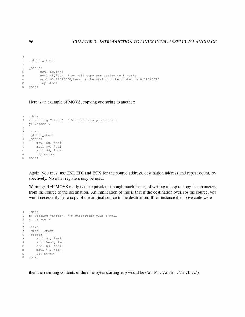
96 CHAPTER 3. INTRODUCTION TO LINUX INTEL ASSEMBLY LANGUAGE
6
7 .globl _start8
9 _start:10 movl $x,%edi11 movl $5,%ecx # we will copy our string to 5 words12 movl $0x12345678,%eax # the string to be copied is 0x1234567813 rep stosl14 done:
Here is an example of MOVS, copying one string to another:
1 .data2 x: .string "abcde" # 5 characters plus a null3 y: .space 64
5 .text6 .globl _start7 _start:8 movl $x, %esi9 movl $y, %edi
10 movl $6, %ecx11 rep movsb12 done:
Again, you must use ESI, EDI and ECX for the source address, destination address and repeat count, re-spectively. No other registers may be used.
Warning: REP MOVS really is the equivalent (though much faster) of writing a loop to copy the charactersfrom the source to the destination. An implication of this is that if the destination overlaps the source, youwon’t necessarily get a copy of the original source in the destination. If for instance the above code were
1 .data2 x: .string "abcde" # 5 characters plus a null3 y: .space 94
5 .text6 .globl _start7 _start:8 movl $x, %esi9 movl %esi, %edi
10 addl $3, %edi11 movl $6, %ecx12 rep movsb13 done:
then the resulting contents of the nine bytes starting at y would be (’a’,’b’,’c’,’a’,’b’,’c’,’a’,’b’,’c’).

3.18. USEFUL WEB LINKS 97
3.18 Useful Web Links
• Linux assembly language Web page: http://linuxassembly.org/
• full as manual: http://www.gnu.org/manual/gas-2.9.1/html_mono/as.html (con-tains full list of directives, register names, etc.; op code names are same as Intel syntax, except forsuffixes, e.g. ‘’l’ in “movl”)
• Intel2gas, converter from Intel syntax to AT&T and vice versa: http://www.niksula.cs.hut.fi/˜mtiihone/intel2gas/
• There are many Web references for the Intel architecture. Just plug “Intel instruction set” into anyWeb search engine.
One such site is http://www.penguin.cz/˜literakl/intel/intel.html.
For more detailed information, see the Intel manual, at ftp://download.intel.com/design/Pentium4/manuals/24547108.pdf. There is an index at the end.
Also, if you need to learn about a specific instruction, often you can get some examples by pluggingthe instruction name and the word example into Google or any other Web search engine. Use thefamily name for the instruction, e.g. MOV instead of movl, movb etc. This will ensure that yoursearch will pick up both Intel-syntax-oriented and AT&T-syntax-oriented sites.
By the way, if you do get information on the Web which is Intel-syntax-oriented, use the intel2gasprogram, mentioned above, to convert it to AT&T.
• NASM assembler home page: http://nasm.2y.net/ I don’t use it myself, but it is useful inthat it is usable on both Linux and Windows
• the ALD debugger: http://ellipse.mcs.drexel.edu/ald.html
• my tutorials on debugging, featuring my slide show, using ddd: http://heather.cs.ucdavis.edu/˜matloff/debug.html
• Unix tutorial: http://heather.cs.ucdavis.edu/˜matloff/unix.html
• Linux installation guide: http://heather.cs.ucdavis.edu/˜matloff/linux.html
3.19 Top-Down Programming
Programming is really mind-boggling work. When one starts a large, complex program, it is really a daunt-ing feeling. One may feel, “Gee, there is so much to do...” It is imperative that you deal with this by usingthe top-down approach to programming, also known as stepwise refinement. Here is what it is.

98 CHAPTER 3. INTRODUCTION TO LINUX INTEL ASSEMBLY LANGUAGE
You start by writing main() (or in assembly language, start()), and—this is key—making sure that itconsists of no more than about a dozen lines of code.36 Since most programs are much bigger than just12 lines, this of course means that some, many most, of these 12 lines will be calls to functions (or in theassembly language case, calls to subroutines). It is important that you give the functions good names, inorder to remind yourself what tasks the various functions will perform.
In a large, complex program, some of those functions will also have a lot to do, so you should impose uponyourself a 12-line on them too! In other words, some functions will themselves consist of calls to even morefunctions.
The point is that this is something easy and somewhat quick to do, something that you can do withoutfeeling overwhelmed. Each 12-line module which you write is simple enough so that you can really focusyour thoughts.
36I’m just using 12 lines as an example. You may prefer a smaller limit, especially when working at the assembly language level.

Chapter 4
More on Intel Arithmetic and LogicOperations
Note: We will assume our machine has a 32-bit word size throughout this chapter.
4.1 Instructions for Multiplication and Division
4.1.1 Multiplication
4.1.1.1 The IMUL Instruction
One of the Intel instructions for multiplication is imull (“IMUL long,” i.e. for 32-bit operations). One formof IMUL is
imull src
where src is a 32-bit multiplier specified in register mode. The multiplicand is implicitly EAX,1 and theproduct is stored in what is described in Intel literature as EDX:EAX. To see what this means, note thatwhen we multiply two 32-bit quantities, we potentially get a 64-bit product. So, the Intel hardware placesthe upper 32 bits in EDX and the lower 32 bits in EAX.
1So, there is only one operand in this form of the instruction, as opposed to the two in the previous form.
99

100 CHAPTER 4. MORE ON INTEL ARITHMETIC AND LOGIC OPERATIONS
4.1.1.2 Issues of Sign
Note that even if the product fits into 32 bits, thus into EAX, we still need to pay attention to EDX. Supposefor instance that the product happens to be -4. In 32-bit form, that is
11111111111111111111111111111100
while in 64-bit form it is
1111111111111111111111111111111111111111111111111111111111111100
In other words, the negative status of -4 is indicated by a 1 in the first of those 64 bits. The 64-bit number
0000000000000000000000000000000011111111111111111111111111111100
is positive. In fact, it has the value 232 − 4, which you can see because we wind backwards four times from
0000000000000000000000000000000100000000000000000000000000000000.
4.1.2 Division
4.1.2.1 The IDIV Instruction
For IDIV, one form is
idivl src
We place the dividend in EDX:EAX and the divisor in src, again with the latter being specified in registeraddressing mode. The quotient then comes out in EAX, and the remainder in EDX. If the quotient is too bigfor 32-bit storage, then an exception, i.e. an execution error will occur.
4.1.2.2 Issues of Sign
As noted for multiplication above, you must be careful with 64-bit quantities. Even if your dividend fits into32 bits, it will be treated as a 64-bit number, with the high bits being in EDX—whether you put them thereor not.
So, if your dividend is nonnegative, make sure to put 0 in EDX; otherwise put -1 there.
A compact and fast way to do this is to use the CWD instruction.

4.1. INSTRUCTIONS FOR MULTIPLICATION AND DIVISION 101
4.1.3 Example
Here is an example of IMUL/IDIV:
1 .text2 .globl _start3 _start:4 movl $2, %ecx5 movl $-1, %eax6 imull %ecx7 idivl %ecx8 done: movl %ebx, %ebx
Let’s use GDB to explore the behavior of these instructions:
1 gdb) r2 Starting program: /www/matloff/public_html/50/PLN/a.out3
4 Breakpoint 1, _start () at g.s:45 4 imull %ecx6 Current language: auto; currently asm7 (gdb) p/x $eax8 $1 = 0xffffffff9 (gdb) p/x $edx
10 $2 = 0x011 (gdb) si12 8 idivl %ecx13 (gdb) p/x $eax14 $3 = 0xfffffffe15 (gdb) p/x $edx16 $4 = 0xffffffff17 (gdb) si18 9 done: movl %ebx, %ebx19 (gdb) p/x $eax20 $5 = 0xffffffff21 (gdb) p/x $edx22 $6 = 0x0
We started with the 32-bit version of -1 in EAX, and 0 in EDX. Multiplying by 2 gives us -2, but IMUL putsits product in 64-bit form in the register pair EDX:EAX. GDB verified this for us. Then we divided by 2,getting -1, but since IDIV puts its result in 32-bit form in the single register EAX, EDX becomes 0.
Or, if we want to view the numbers as unsigned—remember, the nice thing about 2s complement is that wehave our choice of interpretation—then our multiplying by 2 changed 232 − 1 (a number fitting in 32 bits)to 233 − 2 (a 64-bit number).

102 CHAPTER 4. MORE ON INTEL ARITHMETIC AND LOGIC OPERATIONS
4.2 More on Carry and Overflow, and More Jump Instructions
In Chapter 3, we saw how to use instructions like JS, JNZ, etc. to do “if-then-else” tests. This worksfor simple cases with small or moderate-sized numbers. Unfortunately, it is more complicated than this,though, due to problems with the difference between signed and unsigned numbers. To see why, supposefor convenience that we are working with 1-byte quantities (other than convenience, there is nothing specialabout using only one byte here), and consider what happens with
cmpb %al, %bl
when c(AL) = 0x50 and c(BL) = 0xfb. Viewed as signed numbers, c(BL) is smaller, since 80 > −5, butviewed as unsigned numbers, c(AL) is smaller, since 80 < 251.
Recall that the hardware doesn’t know whether we are considering our numbers to be signed or unsigned.So, for example, there is nothing in the hardware for the CMP instruction to distinguish between the signedand unsigned cases, nor is there such a capability in the ADD and SUB instructions.2 However, the hardwaredoes store relevant information in the Carry and Overflow flags, and this will allow us as programmers tohandle the signed and unsigned cases differently on our own, as we will see below.
Before continuing, let’s review at what the hardware does when adding two numbers. It will in any additionsimply add the two numbers bit by bit sequentially from right to left, with carries, in grade-school fash-ion. The hardware is basically treating the numbers as unsigned, but remember, that’s OK even if we areconsidering the numbers to be signed, because the nature of 2s complement storage makies it all work out.
When performing an ADD instruction, the hardware will set or clear the Carry flag (CF), according towhether a carry does occur out of the most significant bit. As noted in Chapter 3, we can programmaticallycheck this by using the JC or JNC instructions. Similarly, the hardware will set or clear the Overflow flag(OF), under certain conditions which we will discuss shortly; our program can check this flag via the JO andJNO instructions.
The term overflow—as opposed to the Overflow flag—informally means that the result of an operation istoo large to fit into the number of bits allocated to it. The definition of “too large” in turn depends on whetherwe are treating the numbers as signed or unsigned.
Again taking the 8-bit case as our example, suppose c(AL) = 0x50 and c(BL) = 0x50, i.e. both registerscontain decimal 80. Their sum, 160, does fit into 8 bits if we are considering our numbers to be unsigned,but if we are thinking of them as signed, then “160” is really -96. So, in this example an overflow will notoccur if the numbers are considered unsigned, but will occur if they are considered signed.
Clearly, if we are considering our numbers to be unsigned, overflow is indicated by the Carry Flag. But whatabout the signed case? The Carry Flag will not tell us (at least not directly) whether overflow has occurred.
2The MIPS chip, by contrast, does have, for instance, both ADD and ADDU instructions for addition. ADD causes an exception,i.e. execution error, upon overflow, while ADDU does nothing to report the problem. C/C++ compilers will use ADDU.

4.2. MORE ON CARRY AND OVERFLOW, AND MORE JUMP INSTRUCTIONS 103
In other words, we’ll need another flag to check overflow in the signed case, and that’s the purpose of theOverflow Flag.
So, how did the Intel engineers design the circuitry which manages the Overflow Flag? Well, let’s first notethat there won’t be an overflow problem if we are adding a nonnegative number to a negative one. Thenonnegative number will be in the range 0 to +127, while the negative one will be between -128 and -1.Then the sum must necessarily be between -128 and +127, thus no overflow.
But a problem can occur if we are adding two positive numbers. They are basically 7 bits each (not countingthe sign bit), so overflow will occur if they have an 8-bit sum. In such a case, there will be a carry out of the7th bit, thus placing a 1 in the 8th bit—thus producing a negative number if we are considering everythingsigned. If you step through this reasoning in the case of adding two negative numbers, you’ll see the problemarises if their sum is positive. In other words:
In signed addition, overflow occurs if and only if the sum of two positive numbers is negativeor the sum of two negative numbers is positive.
Knowing this, the developers of the Intel hardware designed the circuitry so that the Overflow flag would beset if it sees that there is a sign change of the nature described above, and clears the flag otherwise.
Note once again that the hardware doesn’t know whether we are considering our numbers to be signed orunsigned. The developers of the hardware assumed that most people’s typical usage would be signed, andthus they designed the Overflow flag accordingly. If we really are treating our numbers as unsigned, thenwe would have our program check the Overflow flag. But if we are treating them as unsigned, we wouldcheck the Carry flag.
What about subtraction? Recall that it is implemented via addition, i.e. x-y is effected by adding the 2scomplement representation of -y to x, so we are really back to the addition case. But if we are usingsubtraction to set up a conditional jump—typically by using a CMP instruction—we need to worry aboutthe sign flag too, as follows.
• If the Overflow flag is 0, we have nothing to worry about, and can simply look at the Sign flag todetermine whether the subtraction resulted in a negative number.
• If the Overflow is 1, things are a little less simple. Recall that when overflow occurs in an addition(which, recall, is performed for the subtraction process), the sign of the sum is opposite to that of thetwo addends. In other words, an overflow addition changes signs. So, if the subtraction had resultedin a negative difference, which ordinarily would set the Sign flag, the overflow will make the Signflag 0 instead. Conversely, if the difference were not negative, the overflow will make the Sign flag 1,falsely making the difference look negative.
From these considerations, we see that:

104 CHAPTER 4. MORE ON INTEL ARITHMETIC AND LOGIC OPERATIONS
In a subtraction of signed numbers x-y, y will be the larger of the two if and only if the OF 6=SF.
For this reason, the developers of the Intel chip including the JL (“jump if less than”) which jumps if OF 6=SF. This is then the safe way to do less-than comparisons on signed numbers; JS is not safe unless you knowyour numbers are small enough that overflow won’t occur. There are also others. Here is an incompletelist (here “dst” and “src” refer to the destination and source done, for example, in an immediately-previousCMP):
mnemonic action flags checkedJL jump if dst < src SF 6= OFJLE jump if dst ≤ src SF = 1 or SF 6= OFJG jump if dst > src ZF = 0 and SF = OFJGE jump if dst ≥ src SF = OF
There are corresponding instructions for the unsigned case: JB (“jump if below”), JBE (“jump if below orequal”), JA (“jump if above”), and JAE (“jump if above or equal”),
For imull, if the product cannot fit into 32 bits and the high bits go into EDX, both CF and OF are set. (SFand ZF are undefined.) With idivl, all of these flages are undefined.
4.3 Logical Instructions
This section will illustrate one of the most important tools available to the assembly language programmer—data operations at the bit level. Keep these in mind in all your assembly language programming.
In Chapter 3, we saw how to access 16-bit and 8-bit operands. But what can we do in smaller cases, forexample 1-bit operands? The answer is that we cannot do this in a manner directly analogous to the 16-bitand 8-bit cases. The reason for this is that although individual bytes have addresses, individual bits do not.Thus for example there is no 1-bit MOV instruction comparable to movl and movb.
However, we can access individual bits, or groups of bits, in an indirect manner by using the instructionsintroduced in this section.
A logical AND operation does the following: At each bit position in the two operands, the result is 1 if bothoperand bits are 1, and 0 otherwise.
For example,
1011AND 1101
1001

4.3. LOGICAL INSTRUCTIONS 105
In the leftmost bit position of the two operands here, we see two 1s, so there is a 1 in the result. In thesecond-to-the left position, there is a 0 in the first operand and 1 in the second, so there is a 0 in the result,etc.
If we AND together x and y, placing the result back in y, we zero out every bit of y except those correspond-ing to 1s in x; those latter bits of y are left intact.
Suppose for instance that we wish to put a 0 in bit position 1 (second from the right) in EAX, but keep allthe other bits in EAX unchanged. We would use the instruction
andl $0xfffffffd, %eax
because 0xfffffffd has a 0 at bit position 2 and all 1s elsewhere.
Often an AND operation is used as a mask, which is a mechanism by which we can test for certain bits tohave certain values. For example, suppose we wish to jump to a location w if bit positions 15 and 4 have thevalues 1 and 0, respectively, in ECX. We could use the following code to do this:
andl $0x00008010, %ecxcmpl $0x00008000, %ecxjz w
The point is that after the andl is executed, c(ECX) will equal 0x00008000 if and only if the original valuein ECX had 1 and 0 in bit positions 15 and 4.
The & operator in C (the binary operator, not the “address of” operator) performs an AND operation, and infact the compiler will probably translate a statement containing & into and andl instruction.
In an OR operation, if at least one of the two corresponding bits in the two operands is a 1, then the bit inthe result is a 1, while that bit is a 0 otherwise.
The orl (“OR long”) instruction performs an OR operation on the source and destination, placing the resultback in the destination. Again, it is important to note that that means that for every bit in the source operandwhich is a 0, the corresponding bit in the destination remains unchanged, while every 1 in the source willcause the corresponding bit in the destination to become 1. In other words, orl is used to place 1s in desiredspots within the destination while keeping the other destination bits unchanged.
So for example to set bit 2 to 1 in EAX, we would use the instruction
orl $0x00000004, %eax
The | operator in C performs a logical-or operation, and the compiler will usually translate it to orl or otherinstruction from the OR family.

106 CHAPTER 4. MORE ON INTEL ARITHMETIC AND LOGIC OPERATIONS
Logical operations are quite prominent in the programming of device drivers. For example, the built-inspeaker on a PC has a 1-byte port at address 0x61. The least-significant 2 bits must be set to 11 for thespeaker to be on, 00 for off; the other bits contain other important information and must not be changed.I/O ports, as we will see later, are accessed on Intel machines via Intel’s IN and OUT instructions.3 Thefollowing code turns the PC speaker off and on:
1 # to turn speaker on:2 # copy speaker port to AL register3 inb $0x61,%al4 # place 11 in last 2 bits of AL5 orb $3,%al6 # copy back to speaker port7 outb %al,$0x618
9 # to turn speaker off:10 # copy speaker port to AL register11 inb $0x61,%al12 # place 0s in last 2 bits of AL13 andb $0xfc,%al14 # copy back to speaker port15 outb %al,$0x61
The NOT instruction (e.g. notl) changes all 1 bits to 0s and all 0 bits to 1s.
Each bit position in the result of the XOR (“exclusive or”) instruction is equal to 1 if and only if exactly oneof the operands has a 1 at the same bit position.4 It is a classic way of zeroing-out a register using a veryshort instruction. For example,
xorl %ecx, %ecx
will make all bits of ECX equal to 0.
There are also shift operations, which move all bits in the operand to the left or right. The number of bitpositions to shift can be specified either in an immediate constant, or in the CL register.5
For example,
shll $4, %eax
would move all bits in EAX leftward by 4 positions. Note that those which move past the left end are lost,and the bit positions vacated near the right end become 0s. So, for instance, if c(EAX) had been 0xd5fffff3,after the shift it would be 0x5fffff30.
3Accessing them requires status as privileged user.4You can also think of it as adding two bits and taking the sum modulo 2.5Recall that this is the lower 8 bits of ECX.

4.3. LOGICAL INSTRUCTIONS 107
The shrl instruction does the same thing, but rightward.
Note that if we are considering the contents of the operand to be an unsigned integer, a left shift by 4 bits isequivalent to multiplication by 24 = 16, and a right shift by 4 bits is equivalent to division by 16.
If on the other hand we are considering the operand to be a signed integer, we would use sall and sarl, sincethese preserve signs. It is not an issue for multiplication (except for overflow), but it makes a difference fordivision.
This difference is summarized in the comments in the following code:
1 .text2 .globl _start3 _start:4 movl $0x80000000,%eax5 movl $0x80000000,%ebx6 shrl $1,%eax7 sarl $1,%ebx
The point is that though EAX starts out as a negative number, due to having a 1 in its leftmost bit, shiftingEAX one bit rightward will leave a 0 in the leftmost bit, thus rendering EAX positive. In other words,dividing this negative number by 2 (which is what a right-shift of one bit does), which should produceanother negative number, instead produces a positive number. (Of course, if we are interpreting the contentsof EAX to be unsigned, there is no problem.)
On the other hand, the SAR family retains the original sign. After the right-shift is performed, leaving theleftmost bit a 0, SAR replaces that bit with a 1 if the original bit there had been a 1.
Let’s execute this code under GDB:
(gdb) b 9Breakpoint 1 at 0x804805e: file y.s, line 9.(gdb) rStarting program:/fandrhome/matloff/public_html/matloff/public_html/50/PLN/y
Breakpoint 1, _start () at y.s:99 shrl $1,%eaxCurrent language: auto; currently asm(gdb) i reax 0x80000000 -2147483648ebx 0x80000000 -2147483648...(gdb) n_start () at y.s:1010 sarl $1,%ebx(gdb) ndone () at y.s:1111 done: movl %ecx,%ecx(gdb) i r

108 CHAPTER 4. MORE ON INTEL ARITHMETIC AND LOGIC OPERATIONS
eax 0x40000000 1073741824ebx 0xc0000000 -1073741824...
Note both the hex and decimal contents.
In C/C++, left and right shift operations are performed via << and >>. In the latter case, the compiler willtranslate to shrl if the operand is unsigned, and sall in the signed case.
4.4 Floating-Point
Modern Intel CPUs have a built-in Floating-Point unit, which is hardware to perform floating-point add,subtract and so on. Without this hardware, the operations must be performed in software. For example,consider the code
float u,v,w;...w = u + v;
With an Intel CPU, the compiler would implement the addition by generating an FADD (“floating-pointadd”) instruction. If there were no such instruction, the compiler would have to generate a rather lengthamount of code in which one would first decompose u and v into their mantissa and exponent portions,would then change one of the addends in order to match exponent values, would then add the mantissas, etc.The resulting code would run much more slowly would a single FADD instruction.
Intel CPUs have special floating-point registers, each 80 bits wide, thus giving more accuracy than the 32-bit or even 64-bi size. In ATT&T syntax, the registers are named %st(0) (also called simply %st), %st(1),%st(2) and so on. The “st” here stands for “stack,” as the registers are indeed arranged as a stack.
We will learn about stacks in detail in Chapter 7, but the main point is that a stack is a “last-in, first-out” datastructure, meaning that items are removed from the stack in reverse order from which they are inserted. Forinstance, say the stack is initially empty, and then we push, i.e. insert, the numbers 1.8, 302.5 and -29.5222onto the stack. We say that -29.5222 is now at the top of the stack, followed by 302.5 and then 1.8. If wenow pop the stack, that means removing the top element, -29.5222, so that the new top is 302.5, with 1.8next. If we pop again, the stack consists only of 1.8. If we now push 168.8888, then that latter value is ontop, with 1.8 next.
Here is some sample code:
1 .data2 x: .float 1.6253 y: .float 0.0

4.4. FLOATING-POINT 109
4 point25:5 .float 0.256 .text7 .globl _start8 _start:9 flds x # push x onto f.p. stack; x now on top
10 flds point25 # push 0.25; 0.25 now on top, followed by x11 faddp # add the top 2 elts. of the stack, replace 2nd by sum,12 # then pop once; x+0.25 now on top13 fstps y # pop the stack and store the popped value in y
Here we see a new assembler directive, .float. This tells the assembler to arrange things so that when thisprogram is run, the initial value at x in memory will be the (32-bit) representation of the number 1.625.From Chapter 1, we know that this is the bit pattern 0x3fd00000. In fact, we would get the same result from
x: .long 0x3fd00000
and would even save the assembler some work in the process, since it would be spared the effort of converting1.625.6
There are two flds instructions. They are from the FLD (“floating-point load”) Intel family; the ‘s’ heremeans “stack,” just as ‘l’ means “long” in addl from the ADD family.
Read the comments in the code before continuing.
OK, let’s use GDB to learn more about this code:
(gdb) l1 .data2 x: .float 1.6253 y: .float 0.04 point25:5 .float 0.256 .text7 .globl _start8 _start:9 flds x # push x onto f.p. stack10 flds point25 # push 0.25(gdb)11 faddp12 fstps y(gdb) b 12Breakpoint 1 at 0x8048082: file fp.s, line 12.(gdb) rStarting program:/fandrhome/matloff/public_html/matloff/public_html/50/PLN/fp
6That effort would be the same as what scanf() would go through with %f format: It would count the digits after the decimalpoint, finding the number to be 3. It would then convert the characters ‘1’, ‘6’ etc. to 1, 6 and so on, and thus form the numbers 1and 625. Finally it would do something like a = 1 + 625.0/1000.0.

110 CHAPTER 4. MORE ON INTEL ARITHMETIC AND LOGIC OPERATIONS
Breakpoint 1, _start () at fp.s:1212 fstps yCurrent language: auto; currently asm(gdb) nexti0x08048088 in ?? ()(gdb) p/f y$1 = 1.875(gdb) p/x y$2 = 0x3ff00000
Nothing new here, except that we’ve used GDB’s p (“print”) command with f format. Obviously, the latteris similar to %f for printf(). We see that y comes out to 1.875, as expected. We also print out the value ofy as a bit string, which turns out to be 0x3ff00000. You should check that that is indeed the IEEE formatrepresentation of 1.875.
Of course, there are also the obvious instruction families such as FSUB for subtraction, FMUL for multipli-cation and so on. But there are also instruction families that implement transcendental function operations,such as FSIN for sine, FSQRT for square root, etc. Again, by implementing these operations in hardware,we can get large speedups in C/C++ programs that make heavy use of float variables, such as programs thatdo graphics, games, scientific computation and so on.
The Intel hardware also gives the programmer the ability to have fine control over issues such as rounding,via special instructions that control floating-point status registers.

Chapter 5
Introduction to Intel Machine Language
5.1 Overview
This document serves as a brief introduction to Intel machine language. It assumes some familiarity withIntel assembly language (using the AT&T syntax).
5.2 Relation of Assembly Language to Machine Language
Assembly language (AL) is essentially identical to machine language (ML). The only difference is that MLexpresses any machine instruction using the 1s and 0s on which the machine operates, while AL expressesthe same instruction using English-like abbreviations for specific bit patterns.
Consider for instance a register-to-register “move” operation, which copies the contents of one register toanother.1 The bit pattern which signals this, called an op code, is 1000100111. The circuitry is set up so thatwhen the CPU sees 1000100111 in the first ten bits of an instruction, it knows it must do a register-to-registermove.2
As humans we get tired of writing long strings of 1s and 0s, and it would also be burdensome to have toremember which ones signify which op codes. As an alternative, we could hire a clerk. We would say tothe clerk, “Clerk, every time you see me write movl, you enter 1000100111.” The name movl is a lot easierfor us to remember than 1000100111, so would be a great convenience for us (though the poor clerk wouldhave to deal with these things).
1 The term “move” is thus a misnomer, though by now entrenched in computer jargon.2 What do we mean by the “first” 10 bits? An Intel instruction can be several bytes in length. When we speak of the “first” byte
of an instruction, we mean the one contained in the lowest-numbered memory address. When we speak of the “first” bit within abyte, we mean the most-significant bit within that byte.
111

112 CHAPTER 5. INTRODUCTION TO INTEL MACHINE LANGUAGE
The circuity in the CPU is also set up to know that register-to-register “move” instructions, i.e. instructionswhose first bits are 1000100111, are two bytes long.3 Also, the circuity is set up to know that the source anddestination operands of the move—which register is to be copied to which other register—are stored in theremaining six bits in this instruction: The eleventh, twelth and thirteenth bits specify the source register, andthe fourteenth, fifteenth and sixteenth indicate the destination register, according to the following codes:
EAX 000EBX 011ECX 001EDX 010
(The Intel CPU also has a number of other registers, but we will not list their codes here.)
Again, instead of having to remember the code for say, EBX, we would tell the clerk “Whenever I say %ebx,I mean 011,” and so on. Well, our “clerk” is the assembler, e.g. as in standard Unix systems. We use a texteditor to type those same abbreviations into a file, and the assembler converts them to 1s and 0s just as aclerk would.
Remember, though, that we the programmer are still in full control of which instructions (i.e. which opera-tions and operands) to specify, in contrast to a compiler. If for example we type the line
movl %eax,%ebx
into a file, say x.s, we know the assembler will convert it to the machine instruction which does this opera-tion, which we will see below happens to be 1000100111000011, i.e. 0x89c3. By contrast, if we run
y = x + 3;
through a compiler, we have no idea what machine instructions the compiler will generate from it. Indeed,different compilers would likely generate different machine instructions.
The assembler places the machine code it generates, e.g. 1000100111000011 above, into the object file, x.o.
5.3 Example Program
5.3.1 The Code
We ran an assembly language source file, Total.s, through the as assembler with the -a option, the latterrequesting the assembler to print out for us the machine code it produces, side-by-side with our original
3Note that that means that the circuity will advance the Program Counter register by 2, so as to prepare for the fetch of theinstruction which follows the move instruction.

5.3. EXAMPLE PROGRAM 113
assembly language. Here is the output:
GAS LISTING Total.s page 1
12 # finds the sum of the elements of an array34 # assembly/linking Instructions:56 # as -a --gstabs -o total.o Total.s7 # ld -o total total.o89 .data # start of data section1011 x:12 0000 01000000 .long 113 0004 05000000 .long 514 0008 02000000 .long 215 000c 12000000 .long 181617 sum:18 0010 00000000 .long 01920 .text # start of code section2122 .globl _start23 _start:24 0000 B8040000 movl $4, %eax # EAX will serve as a counter for24 0025 # number of words left26 0005 BB000000 movl $0, %ebx # EBX will store the sum26 0027 000a B9000000 movl $x, %ecx # ECX will point to the current27 0028 # element to be summed29 000f 0319 top: addl (%ecx), %ebx30 0011 83C104 addl $4, %ecx # move pointer to next element31 0014 48 decl %eax # decrement counter32 0015 75F8 jnz top # if counter not 0, loop again33 0017 891D1000 done: movl %ebx, sum # done, store result in "sum"33 000034 001d 8D7600
DEFINED SYMBOLSTotal.s:11 .data:00000000 xTotal.s:17 .data:00000010 sumTotal.s:23 .text:00000000 _startTotal.s:29 .text:0000000f topTotal.s:33 .text:00000017 done
NO UNDEFINED SYMBOLS

114 CHAPTER 5. INTRODUCTION TO INTEL MACHINE LANGUAGE
5.3.2 Feedback from the Assembler
Each line in this output is organized as follows:
Display Line Number Memory Offset Contents Assembly Source Line
The offset is a relative memory address, i.e. the distance from the given item to the beginning of its section(.data, .text, etc.).
Here the clerk is saying to us, “Boss, here is what I did with that assembly-language source line of yours,which I’ve shown here in the fourth field. I translated it to the coding you see in the third field, and I arrangedfor this coding to go into the offset I’ve listed in the second field. For your convenience, I’ve also shown theline number from your source file in the first field.”
What does the word offset mean? For instance, look at Line 18. It says that the word which we labeled sumin our source code will be located 0x10 = 16 bytes from the beginning of the .data section.
5.3.3 A Few Instruction Formats
The Contents field shows us the bytes produced by the assembler from our source code, displayed byte-by-byte, in order of increasing address. Note the effect of little-endian-ness, for instance in Line 13. That linesays that our assembly code
.long 5
produced the sequence of bytes 05 00 00 00. That makes sense, right? In the number 00000005, the leastsignificant byte is 05 (recall that a byte is two hex digits), so it will have the lowest address, and thus it willbe displayed first.
The actual address of this word will be determined when the program is linked by ld. The latter will choosea place in memory at which to begin the .data section, and that will determine everything else goes. Ifthat section begins at, say, 0x2020, then for instance the data corresponding to Line 15 will be at case0x2020+0x0c = 0x202c.
Note that the addresses assigned to these items in the .data section of our source file are contiguous andfollow the same order in which we “declared” them in the source file.
Now, let’s learn a few more Intel machine-language formats, to add to the register-to-register move we sawabove. First, let’s consider the one on Line 24.
This instruction is an immediate-to-register move, where the word “immediate” means “the source operandis a constant which appears in the instruction.” Here the constant is 4; it is a 32-bit integer occupying thelast four bytes of this five-byte instruction.

5.3. EXAMPLE PROGRAM 115
This type of instruction is coded by its first five bits being 10111. The next three bits code the destinationregister, in this case being 000. So the first byte of the instruction is 10111000, i.e. 0xb8, followed by theconstant 04000000 (again, note the effect of Intel CPUs being little-endian). We will describe the format forimmediate-to-register move as 10111DDDIMM4, where 10111 is the op code, DDD denotes the destinationregister and IMM4 denotes a 4-byte immediate constant.4
Note also on Line 24 that the offset-field count has been reset back to 0000 again, since we are now in a newsection (.text).
Lines 26 and 27 are similar, but one aspect must be noted in the latter. The immediate constant here, $x, isthe address of x. But all the assembler knows at this point is that later, when the program is linked, x will be0 bytes from the start of the .data section. If ld allocates the .data section at, say, 0x2000, then x will be atthat address. So, ideally the immediate constant placed by the assembler into the machine instruction herewould be 0x2000 (or wherever else the .data section ends up). But, since this value is unknown at assemblytime, the assembler just puts the offset, 0, in the instruction on a temporary basis, to be resolved later by thelinker.
In Line 29 we see an indirect-to-register add. Its op code is 0000001100, followed by three bits for the desti-nation register and then three bits for the source register (the latter being used in indirect mode). We will statethis notationally as 0000001100DDDSSS. An add which is register-to-indirect, e.g. addl %ecx,(%ebx), hasthe format 0000000100SSSDDD.
Of course, the choice of the codes for operations, registers and addressing modes is arbitrary, decided by thehardware designers. Typically it is chosen according to two considerations:
• Instructions which are expected to be more commonly used should have shorter codes, in order toconserve memory and disk space.
• The circuitry may be easier to design, or made faster, with some codes.
In Line 31 we see a register decrement operation. A little experimentation—changing the register to EBXand then observing how the machine code changes—reveals that the format for this kind of instruction is01001DDD, where DDD is the destination register.
5.3.4 Format and Operation of Jump Instructions
There is quite a bit to discuss on Line 32. The format for this jump-if-Zero-flag-not-set instruction is01110101IMM1, where 01110101 is the op code and IMM1 is a 1-byte immediate signed constant whichindicates the target of the jump, i.e. where to jump to if the Zero flag is not set. The constant is actually the(signed) distance to the target, as follows.
4We describe our earlier register-to-register move format as 1000100111SSSDDD.

116 CHAPTER 5. INTRODUCTION TO INTEL MACHINE LANGUAGE
Recall that any computer has a register whose generic name is the Program Counter (PC) which points tothe next instruction to be executed. Let’s say that the .text part of the program starts at 0x300ba. Then theinstruction shown here in Line 32 will be at 0x300ba+0x15 = 0x300cf, and our target (shown in Line 29)will be at address 0x300ba+0xf = 0x300c9.
Recall also that as soon as an instruction is fetched for execution, the PC, which had been pointing to thatinstruction, is incremented to point to the next instruction. In the case of the instruction in Line 32, here ishow the incrementing occurred: The PC had contained 0x300cf, and the CPU fetched the instruction fromthat location. Then the CPU, seeing that the instruction begins with 01110101, realizes that this is a JNZinstruction, thus 2 bytes in length. So, the CPU increments the PC by 2, to point to the instruction in Line33, at 0x300cf+2 = 0x300d1.
Now, to execute the JNZ instruction, the CPU checks the Zero flag. If the flag is not set, the CPU addsthe IMM1 part of the JNZ instruction to the current PC value, treating IMM1 as an 8-bit 2s complementnumber. As such, 0xf8 = -8, so the sum in question will be 0x300d1-8 = 0x300c9. This latter quantity isexactly what we want, the address of our target. The CPU puts this number in the PC, which means thatthe next instruction fetch will be done from location 0x300c9—in other words, we jump to the line we hadnamed top in our assembly language source file, just as desired.
Of course, the assembler knows that the CPU will add IMM1 to the current PC value, and thus sets IMM1accordingly. Specifically, the assembler computes IMM1 to equal the distance from the instruction followingthe JNZ instruction to the target instruction.5
IMM1 is just 8 bits. If the distance to the target is greater than what can be expressed as an 8-bit 2s comple-ment number, the Intel instruction set does have an alternate version of JNZ with format 0000111110000101IMM4.
Keep in mind that the circuitry which implements JNZ will be quite simple. It will check the Zero Flag, andif that flag is 1, the circuitry will then add the second byte of the instruction (-8 in our example here) to theEIP register. That’s all!
5.3.5 Other Issues
The assembler goes through the .s source file line by line, translating each line to the corresponding machinecode. By the time the assembler sees this JNZ instruction, it has already seen the line labeled top. Thus itknows the offset of top within the .text section, and can compute the distance to that target, as we saw here.But what if the jump target were to come after this line with JNZ? In this case, the assembler won’t knowthe offset of the target yet, and thus will not be able to completely translate the instruction yet. Instead, theassembler will make a note to itself, saying that it will come back and finish this line after it finishes its firstpass through the .s file. So, assemblers are two-pass, going through the .s file twice.
5This implies that it doesn’t matter that the execution-time address of top is unknown at assembly time, unlike the case in Line27, where the lack of knowledge of the execution-time address of x caused a problem.
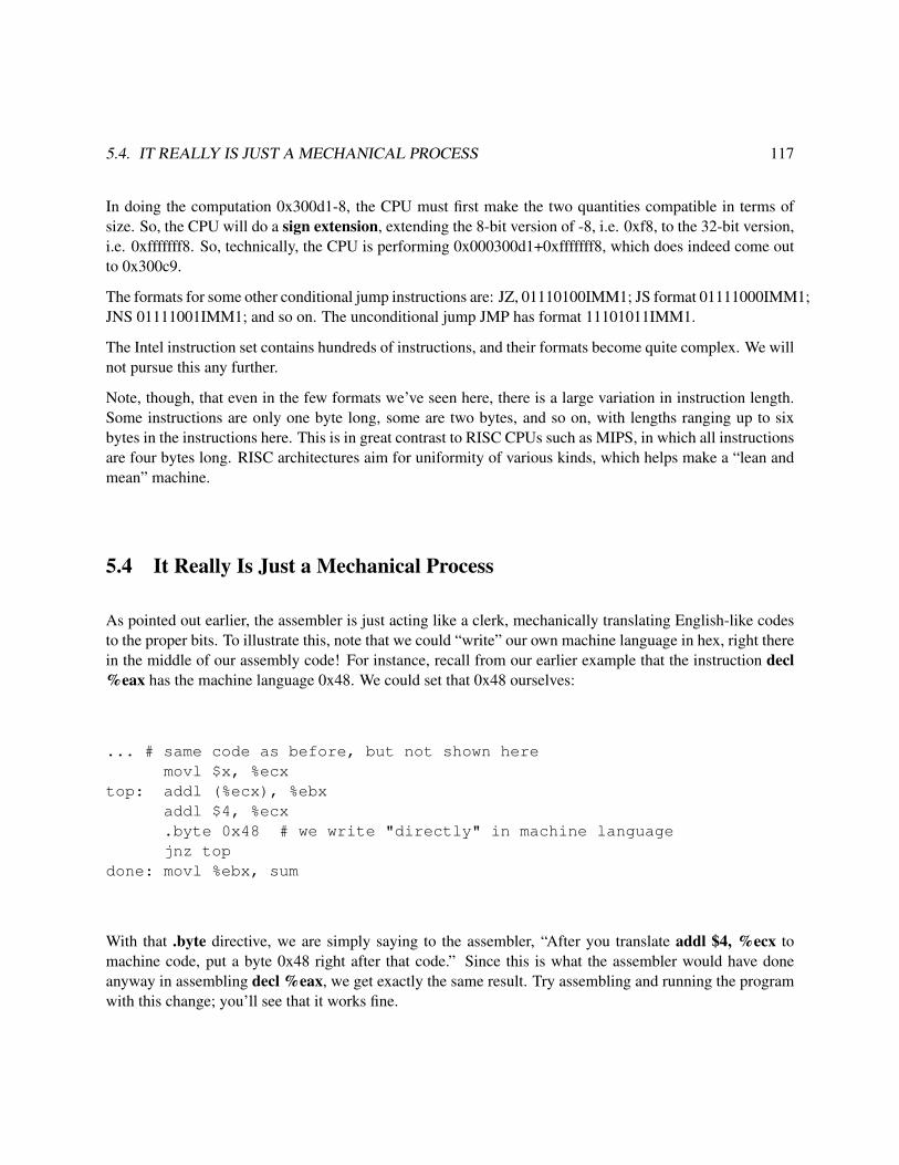
5.4. IT REALLY IS JUST A MECHANICAL PROCESS 117
In doing the computation 0x300d1-8, the CPU must first make the two quantities compatible in terms ofsize. So, the CPU will do a sign extension, extending the 8-bit version of -8, i.e. 0xf8, to the 32-bit version,i.e. 0xfffffff8. So, technically, the CPU is performing 0x000300d1+0xfffffff8, which does indeed come outto 0x300c9.
The formats for some other conditional jump instructions are: JZ, 01110100IMM1; JS format 01111000IMM1;JNS 01111001IMM1; and so on. The unconditional jump JMP has format 11101011IMM1.
The Intel instruction set contains hundreds of instructions, and their formats become quite complex. We willnot pursue this any further.
Note, though, that even in the few formats we’ve seen here, there is a large variation in instruction length.Some instructions are only one byte long, some are two bytes, and so on, with lengths ranging up to sixbytes in the instructions here. This is in great contrast to RISC CPUs such as MIPS, in which all instructionsare four bytes long. RISC architectures aim for uniformity of various kinds, which helps make a “lean andmean” machine.
5.4 It Really Is Just a Mechanical Process
As pointed out earlier, the assembler is just acting like a clerk, mechanically translating English-like codesto the proper bits. To illustrate this, note that we could “write” our own machine language in hex, right therein the middle of our assembly code! For instance, recall from our earlier example that the instruction decl%eax has the machine language 0x48. We could set that 0x48 ourselves:
... # same code as before, but not shown heremovl $x, %ecx
top: addl (%ecx), %ebxaddl $4, %ecx.byte 0x48 # we write "directly" in machine languagejnz top
done: movl %ebx, sum
With that .byte directive, we are simply saying to the assembler, “After you translate addl $4, %ecx tomachine code, put a byte 0x48 right after that code.” Since this is what the assembler would have doneanyway in assembling decl %eax, we get exactly the same result. Try assembling and running the programwith this change; you’ll see that it works fine.

118 CHAPTER 5. INTRODUCTION TO INTEL MACHINE LANGUAGE
5.5 You Could Write an Assembler!
A common exercise in assembly language courses is to write a simple assembler. Even if you are notassigned to do so, it would be a very enriching exercise if you were to at least give some thought as to howyou would do it. For example, just stick to the few instructions covered in this chapter. Your job wouldbe to write a program, say in C, which translates assembly code for the instructions and addressing modescovered in this chapter to machine language.

Chapter 6
Compilation and Linking Process
In learning computer systems, it’s vital to understand how the systems software works. In this chapter, we’lllook at compiling and linking.
6.1 GCC Operations
Say our C program consists of source files x.c and y.c, and we compile as follows:
gcc -g x.c y.c
GCC1 is basically a “wrapper” program, serving only a manager of the compilation process; it does not dothe compilation itself. Instead, GCC will run other programs which actually do the work. We’ll illustratethat here, using the x.c/y.c example throughout.
6.1.1 The C Preprocessor
First GCC will run the C preprocessor, cpp, which processes your #define, #include and other similarstatements. For example:
% cat y.c// y.c
#define ZZZZ 7
1The “English” name of this compiler is the GNU C Compiler, with acronym GCC, so it is customary to refer to it that way.The actual name of the file is gcc.
119

120 CHAPTER 6. COMPILATION AND LINKING PROCESS
#include "w.h"
main(){ int x,y,z;
scanf("%d%d",&x,&y);x *= ZZZZ;y += ZZZZ;z = bigger(x,y);printf("%d\n",z);
}
% cat w.h// w.h
#define bigger(a,b) (a > b) ? (a) : (b)
% cpp y.c# 1 "y.c"# 1 "<built-in>"# 1 "<command line>"# 1 "y.c"
# 1 "w.h" 1# 6 "y.c" 2
main(){ int x,y,z;
scanf("%d%d",&x,&y);x *= 7;y += 7;z = (x > y) ? (x) : (y);printf("%d\n",z);
}
The preprocessor’s output, seen above, now can be used in the next stage:
6.1.2 The Actual Compiler, CC1, and the Assembler, AS
Next, GCC will start up another program, cc1, which does the actual code translation. Even cc1 does notquite do a full compile to machine code. Instead, it compile only to assembly language, producing a file x.sGCC will then start up the assembler, AS (file name as), which translates x.s to a true machine language (1sand 0s) file x.o. The latter is called an object file.
Then GCC will go through the same process for y.c, producing y.o.
Finally, GCC will start up the linker program, LD (file name ld), which will splice together x.o and y.o intoan executable file, a.out. GCC will also delete the intermediate .s and .o files it produced along the way, asthey are no longer needed.

6.2. THE LINKER: WHAT IS LINKED? 121
6.2 The Linker: What Is Linked?
Recall our example above of a C program consisting of two source files, x.c and y.c. We noted that thecompilation command,
gcc -g x.c y.c
would temporarily produce two object files, x.o and y.o, and that GCC would call the linker program, LD tosplice these two files together to form the executable file a.out.
Exactly what does the linker do? Well, suppose main() in x.c calls a function f() in y.c. When the compilersees the call to f() in x.c, it will say, “Hmm...There is no f() in x.c, so I can’t really translate the call, sinceI don’t know the address of f().” So, the compiler will make a little note in x.o to the linker saying, “Dearlinker: When you link x.o with other .o files, you will need to determine where f() is in one of those files,and then finish translating the call to f() in x.c.”2
Similarly, x.c may declare some global variable, say z, which the code in y.c references. The compiler willthen leave a little note to the linker in y.o, etc.
So, the linker’s job is to resolve issues like this before combining the .o files into one big executable file,a.out.
It doesn’t matter whether our original source code was C/C++ or assembly language. Machine code ismachine code, no matter what its source is, so the linker won’t care which original language was the sourceof which .o file.
Though GCC invokes LD, we can run it directly too, which as we have seen is common in the case of writingassembly language code.3
6.3 Headers in Executable Files
Even if our source code consists of just one file (as opposed to, for instance, our example of x.c and y.cabove), so that there is nothing to link, we must still invoke the linker to to produce an executable file. Thereare a couple of reasons for this.
First, in the case of C, you are linking in libraries without realizing it. If you run the ldd command on anexecutable which was compiled from C, you’ll find that the executable uses the C library, libc.so. (Moreon ldd below.) At the very least, that library provides a place to begin execution, the label start which we
2Or, in our GCC command line we may ask the linker to get other functions from libraries. See Section 6.4 below.3We can also apply GCC to the assembly-language file. GCC will notice that the file name has a .s extension, and thus will
invoke the assembler, AS.

122 CHAPTER 6. COMPILATION AND LINKING PROCESS
found in Section 3.4.1 is needed, and sets up your program’s stack. That library also includes many basicfunctions, such as printf() and scanf().
But beyond that, executable files consist not only of the actual machine code but also a header, a kind ofintroduction, at the start of the file. The header will state at what memory locations the various sections areto be loaded, how large the sections are, at what address execution is to begin, and so on. The linker willmake these decisions, and place them in the header.
The are various standard formats for these headers. In Linux, the ELF format is used. If you are curious, theLinux readelf command will tell you what is in the header of any executable file. By running this commandwith, e.g., the -s option, you can find out the final addresses assigned to your labels by the linker.4
There are headers in object files as well; the Linux command objdump will display these for you.
6.4 Libraries
A library is a conglomeration of several object files, collected together in one convenient place. Librariescan be either static or dynamic, as explained below. In Unix, library names end with .a (static) or .so(dynamic), possibly followed by a version number.5 The names also usually start with “lib,” so that forexample libc.so.6 is version 6 of the C library.
When you need code from a static library, the linker physically places the code in with your machine code.In the dynamic case, though, the linker merely places a note in your machine code, which states whichlibraries are needed; at run time, the OS will do the actual linking then. Dynamic libraries save a lot of diskspace and memory (at the slight cost of a bit of a delay in loading the program into memory at run time),since we only need a single copy of any given library. Here is an overview of how the libraries are createdand used:
One creates a static library by applying the ar command to the given group of .o files, and then possiblyrunning ranlib. For example:
% gcc -c x.c% gcc -c y.c% ar lib8888.a x.o y.o% ranlib lib8888.a
Later, if someone wants to check what’s inside a static library, one runs ar on the .a file, with the t option,e.g.
4A more common command for this is nm. It’s more general, as it does not apply only to ELF files, but it only gives symbolinformation.
5You may have encountered dynamic libraries on Windows systems, which have the suffix .dll.

6.4. LIBRARIES 123
% ar t lib8888.a
To create a dynamic library, one needs to use the -fPIC option when compiling to produce the .o files, andthen one compiles the library by using GCC’s -shared option, e.g.
% gcc -g -c -fPIC x.c% gcc -g -c -fPIC y.c% gcc -shared -o lib8888.so x.o y.o
In systems that use ELF, you can check what’s in a dynamic library by using readelf, e.g.
% readelf -s lib8888.so
When you link to a library, GCC’s -l option can be used to state which library to link in. For example, if youhave a C program w.c which calls sqrt(), which is in the math library libm.so, you would type
% gcc -g w.c -lm
The notation “-lxxx” means “link the library named libxxx.a or libxxx.so.”
One point to note, though, is that the library you need may not be in the default directories /usr/lib, /lib andthose listed in /etc/ld.so.cache. If for example your library libqrs.so is in the directory /a/b/c , you wouldtype
% gcc -g w.c -lqrs -L/a/b/c
This is fine in the static case, but remember that in the dynamic case, the library is not actually acquiredat link time. All that is put in our executable file is the name of the library, but NOT its location. In otherwords, in the dynamic case, the -L/a/b/c in the example above is used by the linker to verify that the librarydoes exist, but this location is NOT recorded. When the program is actually run, the OS will still look onlyin the default directories. There are various ways to tell it to look at others. One of the ways is to specify/a/b/c within the Unix environment variable LD LIBRARY PATH, e.g.
% setenv LD_LIBRARY_PATH /a/b/c
If you need to know which dynamic libraries an executable file needs, run ldd, e.g.
% ldd a.out
Clearly this is a complex topic. If you ever need to know more than what I have in this introduction, plugsomething like “shared library tutorial” into a Web search engine.

124 CHAPTER 6. COMPILATION AND LINKING PROCESS
6.5 A Look at the Final Product
So, let’s say we take our first sample program, in Section 3.4, and assemble it and link it, with the executablefile being tot.
Recall that we had .data and .text sections. The linker chooses addresses for the sections. We can determinethose, for example, by running
% readelf -s tot
on our executable file tot. The relevant excerpt of the output is
9: 08049094 0 NOTYPE LOCAL DEFAULT 2 x10: 080490a4 0 NOTYPE LOCAL DEFAULT 2 sum11: 08048083 0 NOTYPE LOCAL DEFAULT 1 top12: 0804808b 0 NOTYPE LOCAL DEFAULT 1 done13: 08048074 0 NOTYPE GLOBAL DEFAULT 1 _start
So we see that ld has arranged things so that, when our program is loaded into memory at run time, the .datasection will start at 0x08049094 and the .text section at 0x08048074.
We can use GDB to confirm that these addresses really hold at run time:
% gdb tot(gdb) p/x &x$1 = 0x8049094(gdb) p/x &_start$2 = 0x8048074
We can also confirm that the linker really did fix the temporary machine code the assembler had producedfrom
movl $x, %ecx
Recall that the assembler didn’t know the address of x, since the location of the .data section would not beset until later, when the linker ran. So, the assembler left a note in the .o file, asking the linker to put in thereal address. Let’s check that it did:
(gdb) b 24Breakpoint 1 at 0x804807e: file tot.s, line 24.(gdb) rStarting program: /root/50/totBreakpoint 1, _start () at tot.s:24

6.5. A LOOK AT THE FINAL PRODUCT 125
24 movl $x, %ecx # ECX will point to the currentCurrent language: auto; currently asm(gdb) disassembleDump of assembler code for function _start:0x08048074 <_start+0>: mov $0x4,%eax0x08048079 <_start+5>: mov $0x0,%ebx0x0804807e <_start+10>: mov $0x8049094,%ecxEnd of assembler dump.(gdb) x/5b 0x0804807e0x804807e <_start+10>: 0xb9 0x94 0x90 0x04 0x08
We see that the machine code for the instruction really does contain the actual address of x.

126 CHAPTER 6. COMPILATION AND LINKING PROCESS

Chapter 7
Subroutines on Intel CPUs
7.1 Overview
Programming classes usually urge the students to use top-down and modular design in their coding. Thisin turn means using a lot of calls to functions or methods in C-like languages, which are called subroutinesat the machine/assembly level.1
This document serves as a brief introduction to subroutine calls in Intel machine language. It assumes somefamiliarity with Intel 32-bit assembly language, using the AT&T syntax with Linux.
7.2 Stacks
Most CPU types base subroutine calls on the notion of a stack. An executing program will typically havean area of memory defined for use as a stack. Most CPUs have a special register called the stack pointer(SP in general, ESP on 32-bit Intel machines), which points to the top of the stack.
Note carefully that the stack is not a “special” area of memory, say with a “fence” around; wherever SPpoints, that is the stack. And that is true even if we aren’t using a stack at all, in which case the “stack” isgarbage.
Stacks typically grow toward memory address 0.2 If an item is added—pushed—onto the stack, the SP isdecremented to point to the word preceding the word it originally pointed to, i.e. the word with the next-lower address than that of the word SP had pointed to beforehand. Similarly SP is incremented if the itemat the top of the stack is popped, i.e. removed. Thus the words following the top of the stack, i.e. with
1This latter term is also used in various high-level languages, such as FORTRAN and Perl.2For this reason, we usually draw the stack with memory address 0 at the top of the picture, rather than the bottom.
127

128 CHAPTER 7. SUBROUTINES ON INTEL CPUS
numerically larger addresses, are considered the interior of the stack.
Say for example we wish to push the value 35 onto the stack. Intel assembly language code to do this wouldbe, for instance,
subl $4,%esp # expand the stack by one wordmovl $35,(%esp) # put 35 in the word which is the new top-of-stack
However, typically a CPU will include a special instruction to do pushes. On Intel machines, for example,we could do the above using just one instruction:3
push $35
(There is also a pushl instruction, for consistency with instructions like movl, but it is just another name forpush. Note that this is because the items on the stack must be of word size anyway.)
By the way, instructions like
pushl w
where w is a label in the .data section, are legal, a rare exception to Intel’s theme of not allowing directmemory-to-memory operations.
Similarly, if we wish to pop the stack and have the popped value placed in, say, ECX, we would write
pop %ecx
Note carefully that it is the stack which is popped, not the ECX register.
Keep in mind that a pop does not change memory. The item is still there; the only change is that it isnot considered part of the stack anymore. And the stack pointer merely is a means for indicating what isconsidered part of the stack; by definition, the stack consists of the word pointed to by ESP plus all wordsat higher addresses than that. The popped item will still be there in memory until such time, if any, thatanother push is done, overwriting the item.
A process’ amount of stack space is set when the program is loaded. One can run the Linux commands limit(C shell) and ulimit (Bash shell) to change this value.
3This would be not only easier to program, but more importantly would also execute more quickly.

7.3. CALL, RET INSTRUCTIONS 129
7.3 CALL, RET Instructions
The actual call to a subroutine is done via a CALL instruction. Execution of this instruction consists of twoactions:
• The current value of the PC is pushed on the stack.
• The address of the subroutine is placed into the PC.
We say that the first of these two actions pushes the return address onto the stack, meaning the place thatwe wish to return to after we finish executing the subroutine.
Note that both of the actions above, like those of any instruction, are performed by the hardware.
For example, consider the code
call abcaddl %eax,%ebx
At first the PC is pointing to the call instruction. After the instruction is fetched from memory, the CPU, asusual, increments the PC to point to the next instruction, i.e. the addl. From the first bullet item above, wesee that that latter instruction’s address will be pushed onto the stack — which is good, because we do wantto save that address, as it is the place we wish to return to when the subroutine is done. So, the terminologyused is that the call instruction saves the return address on the stack.
What about the second bullet item above? Its effect is that we do a jump to the subroutine. So, what calldoes is save the return address on the stack and then start execution of the subroutine.
The very last instruction which the programmer puts into the subroutine will be ret, a return instruction. Itpops the stack, and places that popped value into the PC. Since the return address had been earlier pushedonto the stack, we now pop it back off, and the return address will now be in the PC — so we are executingthe instruction immediately following the call, such as the addl in the example above, just as desired.4
7.4 Arguments
Functions in C code usually have arguments (another term used is parameters), and that is also true inassembly language. The typical way the arguments are passed to the subroutine is again via the stack. Wesimply push the arguments onto the stack before the call, and then pop them back off after the subroutine isdone.
4This assumes we’ve been careful to first pop anything we pushed onto the stack subsequent to the call. More on this later.

130 CHAPTER 7. SUBROUTINES ON INTEL CPUS
For instance, in the example above, suppose the subroutine abc has two integer arguments, and in thisparticular instance they will have the values 3 and 12. Then the code above might look like
push $12push $3call abcpop %edx # assumes EDX isn’t saving some other data at this timepop %edxaddl %eax,%ebx
The subroutine then accesses these arguments via the stack. Say for example abc needs to add the twoarguments and place their sum in ECX. It could be written this way:
...movl 4(%esp),%ecxaddl 8(%esp),%ecx...ret
In that movl, the source operand is 4 bytes past where SP is pointing to, i.e. the next-to-top element of thestack. In the call example above, this element will be the 3. (The top element of the stack is the returnaddress, since it was the last item pushed.) The second addl picks up the 12.
Here’s what the stack looks like at the time we execute that movl:
argument 2argument 1
ESP→ saved return addresstowards 0 ↓
7.5 Ensuring Correct Access to the Stack
But wait a minute. What if the calling program above had also been storing something important in ECX?We must write abc to avoid a clash. So, we first save the old value of ECX—where else but the stack?—andlater restore it. So, the beginning and end of abc might look like this:
push %ecx...movl 8(%esp),%ecxaddl 12(%esp),%ecx... # ECX used herepop %ecxret
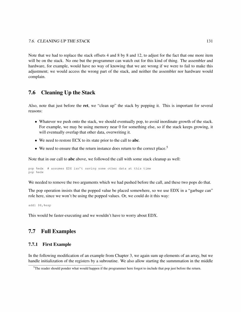
7.6. CLEANING UP THE STACK 131
Note that we had to replace the stack offsets 4 and 8 by 8 and 12, to adjust for the fact that one more itemwill be on the stack. No one but the programmer can watch out for this kind of thing. The assembler andhardware, for example, would have no way of knowing that we are wrong if we were to fail to make thisadjustment; we would access the wrong part of the stack, and neither the assembler nor hardware wouldcomplain.
7.6 Cleaning Up the Stack
Also, note that just before the ret, we “clean up” the stack by popping it. This is important for severalreasons:
• Whatever we push onto the stack, we should eventually pop, to avoid inordinate growth of the stack.For example, we may be using memory near 0 for something else, so if the stack keeps growing, itwill eventually overlap that other data, overwriting it.
• We need to restore ECX to its state prior to the call to abc.
• We need to ensure that the return instance does return to the correct place.5
Note that in our call to abc above, we followed the call with some stack cleanup as well:
pop %edx # assumes EDX isn’t saving some other data at this timepop %edx
We needed to remove the two arguments which we had pushed before the call, and these two pops do that.
The pop operation insists that the popped value be placed somewhere, so we use EDX in a “garbage can”role here, since we won’t be using the popped values. Or, we could do it this way:
addl $8,%esp
This would be faster-executing and we wouldn’t have to worry about EDX.
7.7 Full Examples
7.7.1 First Example
In the following modification of an example from Chapter 3, we again sum up elements of an array, but wehandle initialization of the registers by a subroutine. We also allow starting the summmation in the middle
5The reader should ponder what would happen if the programmer here forgot to include that pop just before the return.

132 CHAPTER 7. SUBROUTINES ON INTEL CPUS
of the array, by specifying the starting point as an argument to the subroutine, and allow specification thatonly a given number of elements be summed:
1 .data2 x:3 .long 14 .long 55 .long 26 .long 187 .long 88888 .long 1689 n: .long 3
10 sum:11 .long 012
13 .text14 # EAX will contain the number of loop iterations remaining15 # EBX will contain the sum16 # ECX will point to the current item to be summed17
18 .globl _start19 _start:20 # push the arguments before call: place to start summing, and21 # number of items to be summed22 push $x+4 # here we specify to start summing at the 523 push n # here we specify how many to sum24 call init25 addl $8, $esp # clean up the stack26 top: addl (%ecx), %ebx27 addl $4, %ecx28 decl %eax29 jnz top30 done: movl %ebx, sum31
32 init:33 movl $0, %ebx34 # pick up arguments from the stack35 mov 8(%esp), %ecx36 mov 4(%esp), %eax37 ret
Here is the output assembly listing:
GAS LISTING full.s page 11 .data2 x:3 0000 01000000 .long 14 0004 05000000 .long 55 0008 02000000 .long 26 000c 12000000 .long 187 0010 B8220000 .long 88888 0014 A8000000 .long 1689 0018 03000000 n: .long 310 sum:

7.7. FULL EXAMPLES 133
11 001c 00000000 .long 01213 .text14 # EAX will contain the number of loop iterations remaining15 # EBX will contain the sum16 # ECX will point to the current item to be summed1718 .globl _start19 _start:20 # push the arguments before call: place to start summing, and21 # number of items to be summed22 0000 68040000 push $x+4 # here we specify to start summing at the 522 0023 0005 FF351800 push n # here we specify how many to sum23 000024 000b E8110000 call init24 0025 0010 83C408 addl $8, %esp # clean up the stack26 0013 0319 top: addl (%ecx), %ebx27 0015 83C104 addl $4, %ecx28 0018 48 decl %eax29 0019 75F8 jnz top30 001b 891D1C00 done: movl %ebx, sum30 00003132 init:33 0021 BB000000 movl $0, %ebx33 0034 # pick up arguments from the stack35 0026 8B4C2408 mov 8(%esp), %ecx36 002a 8B442404 mov 4(%esp), %eax37 002e C3 ret
DEFINED SYMBOLSfull.s:2 .data:00000000 xfull.s:9 .data:00000018 nfull.s:10 .data:0000001c sumfull.s:19 .text:00000000 _startfull.s:32 .text:00000021 initfull.s:26 .text:00000013 topfull.s:30 .text:0000001b done
NO UNDEFINED SYMBOLS
Note from line 24 of the assembly output listing that the CALL instruction assembled to e811000000. Thatbreaks down to an op code of e8 and a distance field of 11000000. The latter (after accounting for little-endianness) is the distance from the instruction after the CALL to the subroutine, which from lines 25 and33 can be seen to be 0x0021-0x0010 = 0x11.6
6This is what is known for Intel machines as a near call. Back in the days when Intel CPUs could only access 64K segment ofmemory at a time, they needed “near” (within-segment) and “far” (inter-segment) calls, but with the flat 32-bit addressing modelused today, this is outmoded, and everything is “near.”

134 CHAPTER 7. SUBROUTINES ON INTEL CPUS
Note that in the call to addone(), the argument was the address of x, not x itself. Thus the push instructiongenerated by the compiler pushes $x, not x. By contrast, in the translation of the call to printf(), x is pushed.Note that the format string is an argument too.
To gain a more concrete understanding of how the stack is used in subroutine calls, let’s use GDB to inspectwhat happens with the stack when this program is run:
% gdb a.outGNU gdb Red Hat Linux (5.2.1-4)Copyright 2002 Free Software Foundation, Inc....Breakpoint 1, _start () at SubArgsEx.s:2424 call initCurrent language: auto; currently asm(gdb) p/x $eip$1 = 0x804807f(gdb) p/x $esp$2 = 0xbfffcec8(gdb) si33 movl $0, %ebx(gdb) p/x $eip$3 = 0x8048093(gdb) p/x $esp$4 = 0xbfffcec4(gdb) x/3w $esp0xbfffcec4: 0x08048084 0x00000003 0x080490a8(gdb) p/x &x$5 = 0x80490a4
So, the PC value changed from 0x804807f to 0x0x8048093, reflecting the fact that a CALL does do a jump.
The CALL also does a push (of the return address), and sure enough, the stack did expand by one word, ascan be seen by the fact that ESP decreased by 4, from 0xbfffcec8 to 0xbfffcec4.
The stack should now have the return address at the top, followed by the value of n and the address of xplus 4. Let’s check that return address. The PC value just before the call had been, according our GDBoutput above, 0x804807f, and since (as discovered above from the output of as -a) the CALL was a 5-byteinstruction, the saved return address should be 0x804807f+5 = 0x8048084, which is indeed what we see onthe top of the stack.
By the way, you should be able to deduce the address at which the .text section begins. Do you see how?
7.7.2 If the PC Points to Garbage, the Machine Will Happily “Execute” the Garbage
Now look at the rest of our GDB session:
(gdb) b doneBreakpoint 2 at 0x804808d: file SubArgsEx.s, line 30.

7.7. FULL EXAMPLES 135
(gdb) cContinuing.
Breakpoint 2, done () at SubArgsEx.s:3030 done: movl %ebx, sum(gdb) si33 movl $0, %ebx(gdb) p sum$6 = 25(gdb) si35 mov 8(%esp), %ecx(gdb) qThe program is running. Exit anyway? (y or n) y
After executing the instruction at done, I checked to see if sum was correct, which it was. At that point, Ireally should have stopped, since the program was indeed done. But I continued anyway, issuing another sicommand to GDB. Did GDB refuse? Did “the little man inside the computer” refuse? Heck, no! Remember,it’s just a dumb machine. The CPU has no idea that the instruction at done was the last instruction in theprogram. So, it keeps going, executing the next instruction in memory. That instruction is the MOV at thebeginning of the subroutine init()! So, you can see that there is nothing “special” about a subroutine. Thereis no physical boundary between modules of code, in this case between the calling module and init(). It’sall just a bunch of instructions.
In the late 1980s, it was not common for personal computers to have virtual memory hardware, nor anoperating system (OS) to take advantage of that hardware if it does exist. Imagine what happened whena user ran a recursive function, and through error, had not provision to terminate the recursion. Each callwould push material on the stack, resulting in the stack pointer getting closer and closer to 0. But when itreached 0, it would keep going! Remember, -4 is simply a very large positive number if viewed as unsigned,which addresses are. So, the program would keep going, and the stack would keep growing.
Eventually the stack would grow to a point at which a push operation would write over the program itself!This would eventually cause garbage to be executed, which would likely result at some point in executionof an “instruction” that has a nonexistent op code. This would crash the program.
Along the way, the stack would also overwrite the OS. This would not immediately cause a problem, as theOS is dormant while your program is running. If your program makes a system call, such as for input/output,that by definition is a call to the OS, so trouble might arise then. But the recursive function in our examplewould probably not do this.
7.7.3 Second Example
The next example speaks for itself, through the comments at the top of the file. By the way, when you readthrough it, make sure you understand what we are doing with the SHR instruction.

136 CHAPTER 7. SUBROUTINES ON INTEL CPUS
1 # the subroutine findfirst(v,w,b) finds the first instance of a value v in a2 # block of w consecutive words of memory beginning at b, returning3 # either the index of the word where v was found (0, 1, 2, ...) or -1 if4 # v was not found; beginning with _start, we have a short test of the5 # subroutine6
7 .data # data section8 x:9 .long 1
10 .long 511 .long 312 .long 16813 .long 888814 .text # code section15 .globl _start # required16 _start: # required to use this label unless special action taken17 # push the arguments on the stack, then make the call18 push $x+4 # start search at the 519 push $4 # search 4 words20 push $168 # search for 16821 call findfirst22 done:23 movl %edi, %edi # dummy instruction for breakpoint24 findfirst:25 # finds first instance of a specified value in a block of words26 # EBX will contain the value to be searched for27 # ECX will contain the number of words to be searched28 # EAX will point to the current word to search29 # return value (EAX) will be index of the word found (-1 if not found)30 # fetch the arguments from the stack31 movl 4(%esp), %ebx32 movl 8(%esp), %ecx33 movl 12(%esp), %eax34 movl %eax, %edx # save block start location35 # top of loop; compare the current word to the search value36 top: cmpl (%eax), %ebx37 jz found38 decl %ecx # decrement counter of number of words left to search39 jz notthere # if counter has reached 0, the search value isn’t there40 addl $4, %eax # otherwise, go on to the next word41 jmp top42 found:43 subl %edx, %eax # get offset from start of block44 shrl $2, %eax # divide by 4, to convert from byte offset to index45 ret46 notthere:47 movl $-1, %eax48 ret
7.8 Interfacing C/C++ to Assembly Language
Programming in assembly language is very slow, tedious and unclear, so we try to avoid it, sticking to high-level languages such as C. But in some cases we need to write part of a program in assembly language,

7.8. INTERFACING C/C++ TO ASSEMBLY LANGUAGE 137
either because there is something which is highly machine-dependent,7 or because we need extra programspeed and this part of the program is the main time consumer.
A good example is Linux. Most of it is written in C, for convenience and portability across machines,but small portions are written in assembly language, to get access to certain specific features of the givenhardware. When Linux is ported to a new type of hardware, these portions must be rewritten, but fortunatelythey are small.
At first it might seem “unnatural” to combine C and assembly language. But remember, both .c and .s filesare translated to machine language, so we are just combining machine language with machine language, notunnatural at all.
7.8.1 Example
So, here we will see how we can interface C code to an assembly language subroutine. Here is our C code:
1 // TryAddOne.c, example of interfacing C to assembly language2 // paired with AddOne.s, which contains the function addone()3 // compile by assembling AddOne.s first, and then typing4 //5 // gcc -g -o tryaddone TryAddOne.c AddOne.o6 //7 // to link the two .o files into an executable file tryaddone8 // (recall the gcc invokes ld)9
10 int x;11
12 main()13
14 { x = 7;15 addone(&x);16 printf("%d\n",x); // should print out 817 exit(1);18 }19
I wrote the function addone() in assembly language. In order to do so, I needed to know how the C compilerwas going to translate the call to addone() to machine/assembly language. In order to determine this, Icompiled the C module with the -S option, which produces an assembly language version of the compiledcode:
1 % gcc -S TryAddOne.c2 % more TryAddOne.s
7Note that to a large extent we can deal with machine-dependent aspects even from C. We can deal with the fact that differentmachines have different word sizes, for example, by using C’s sizeof() construct. However, this is not the case for some othersituations.

138 CHAPTER 7. SUBROUTINES ON INTEL CPUS
3 .file "TryAddOne.c"4 .version "01.01"5 gcc2_compiled.:6 .section .rodata7 .LC0:8 .string "%d\n"9 .text
10 .align 411 .globl main12 .type main,@function13 main:14 pushl %ebp15 movl %esp, %ebp16 subl $8, %esp17 movl $7, x18 subl $12, %esp19 pushl $x20 call addone21 addl $16, %esp22 subl $8, %esp23 pushl x24 pushl $.LC025 call printf26 addl $16, %esp27 subl $12, %esp28 pushl $129 call exit30 .Lfe1:31 .size main,.Lfe1-main32 .comm x,4,433 .ident "GCC: (GNU) 2.96 20000731 (Red Hat Linux 7.1 2.96-85)"34 %
There is quite a lot in that .s output file, but the part of interest to us here, for the purpose of writing addone(),is this:
pushl $xcall addone
This confirms what we expected, that the compiler would produce code that transmits the argument toaddone() by pushing it onto the stack before the call.8 So, we write addone() so as to get the argument fromthe stack:
1 # AddOne.s, example of interfacing C to assembly language2 #3 # paired with TryAddOne.c, which calls addone4 #5 # assemble by typing6 #7 # as --gstabs -o AddOne.o AddOne.s
8Note, though, that the compiler also first expanded the stack by 12 bytes, for no apparent reason. More on this below.

7.8. INTERFACING C/C++ TO ASSEMBLY LANGUAGE 139
8 #9
10 # note that we do not have a .data section here, and normally would not;11 # but we could do so, and if we wanted that .data section to be visible12 # from the calling C program, we would have .globl lines for whatever13 # labels we have in that section14
15 .text16
17 # need .globl to make addone visible to ld18 .globl addone19
20 addone:21
22 # will use EBX for temporary storage below, and since the calling23 # module might have a value there, better save the latter on the stack24 # and restore it when we leave25 push %ebx26
27 # at this point the old EBX is on the top of the stack, then the28 # return address, then the argument, so the latter is at ESP+829
30 movl 8(%esp), %ebx31
32 incl (%ebx) # need the (), since the argument was an address33
34 # restore value of EBX in the calling module35 pop %ebx36
37 ret
The comments here say we should save, and later restore, the EBX register contents as they were prior to thecall. Actually, our main() here does not use EBX in this case (see the assembly language version above),but since we might in the future want to call addone() from another program, it’s best practice to protectEBX as we have done here.
So, by the time we reach the movl instruction, the stack looks like this:
argumentsaved return address
ESP→ saved EBX valuetowards 0 ↓
The movl instruction thus needs to go 8 bytes deep into the stack to pick up the argument, which wasthe address of the word to be incremented. Then the incl instruction does the incrementing via indirectaddressing, again since the argument is an address.
The reader is urged to compile/assemble/link as indicated in the comments in the .c and .s files above, andthen execute the program, to see that it does indeed work. Seeing it actually happen will increase yourunderstanding!

140 CHAPTER 7. SUBROUTINES ON INTEL CPUS
Note carefully that TryAddOne.c and AddOne.s are not “programs” by themselves. They are each thesource code for a different portion of the same program, the executable file tryaddone. This is no differentfrom the situation in which we have C source code in two .c files, compile them into two .o files, and thenlink to make a single executable.
7.8.2 Cleaning Up the Stack?
Let’s check whether the compiler fulfilled its “civic responsibility ” by cleaning up the stack after the call.In the .s file produced by gcc -S above, we saw this code:
subl $12, %esppushl $xcall addoneaddl $16, %espsubl $8, %esp
This is a bit odd. Since we had only pushed one argument, i.e. one word, the natural cleanup would havebeen to then pop one word, as follows:
call addoneaddl $4, %esp
(or use a pop instruction instead of the addl). In other words, we should shrink the stack by 4 bytes after thecall. Yet the net effect of the code generated by the compiler is to shrink the stack by 16 - 8 = 8 bytes, not 4.
On the other hand, recall that with the instruction
subl $12, %esp
the compiler expanded the stack by 12 bytes too much before the call. In other words, the overall effect ofthe call has been to expand the stack by 12 - (16-8) = 4 bytes!
Supposedly the GCC people designed things this way, to leave gaps between one call and the next on thestack. This has makes things a little safer, as it is harder for a return address to be accidentally overwritten.
7.8.3 More Sections
By the way, the compiler has used the .comm directive to set up storage for our global variable x. It asks for4 bytes of space, aligned on an address which is a multiple of 4. (See Section 1.3.1.1.) The linker will laterset things up so that the variable x will be stored in the .bss section, which is like the .data section exceptthat the data is uninitialized. Recall that in our program above, the declaration of x, a global variable, wassimply

7.8. INTERFACING C/C++ TO ASSEMBLY LANGUAGE 141
int x;
If instead the declaration had been
int x = 28;
then x would be in the .data section.
Also, the label .LC0 is in yet another kind of section, .rodata (“read-only data”).
The reader is strongly encouraged to run the Unix nm command on any executable file, say the compiledversion of the C program here. In the output of that command, symbols (names of functions and globalvariables) are marked as T, D, B, R and so on, indicating that the item is in the .text section, .data section,.bss section, .rodata section, etc., and the addresses assigned to them by the linker are shown.
In Linux, the stack section begins at address 0xbfffffff, and as mentioned, grows toward 0. The heap, fromwhich space is allocated dynamically when your program calls malloc() or invokes the C++ operator new,starts at 0xbffff000 and grows away from 0.
7.8.4 Multiple Arguments
What if addone() were to have two arguments?9 A look at the output of the compilation of the call toprintf() above shows that arguments are pushed in reverse order, in this case the second before the first.So, if addone() were to have two arguments, we would have to write the code for the function accordingly,making use of the fact that the first argument will be closer to the top of the stack than the second.
7.8.5 Nonvoid Return Values
The above discussion presumes that return value for the assembly language function is void. If this is not thecase, then the assembly language function must place the return value in the EAX register. This is becausethe C compiler will place code after the call to the function which picks up the return value from EAX.
That assumes that the return value fits in EAX, which is the case for integer, character or pointer values. Itis not the case for the type long long in GCC, implemented on 32-bit Intel machines in 8 bytes. If a functionhas type long long, GCC will return the value in the EDX:EAX pair, similar to the IMUL case.
The case of float return values is more complicated. The Intel chip has separate registers and stack forfloating-point operations. See Chapter 4.
9Note that when the C compiler compiles TryAddOne.c above, it does not know how many arguments addone() really has,since addone() is in a separate source file. (The compiler won’t even know whether that source file is C or assembly code.) Itsimply knows how many arguments we have used in this call, which need not be the same.
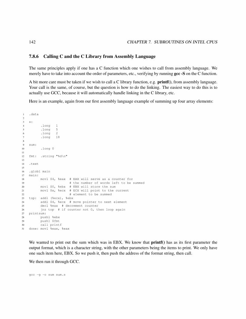
142 CHAPTER 7. SUBROUTINES ON INTEL CPUS
7.8.6 Calling C and the C Library from Assembly Language
The same principles apply if one has a C function which one wishes to call from assembly language. Wemerely have to take into account the order of parameters, etc., verifying by running gcc -S on the C function.
A bit more care must be taken if we wish to call a C library function, e.g. printf(), from assembly language.Your call is the same, of course, but the question is how to do the linking. The easiest way to do this is toactually use GCC, because it will automatically handle linking in the C library, etc.
Here is an example, again from our first assembly language example of summing up four array elements:
1 .data2
3 x:4 .long 15 .long 56 .long 27 .long 188
9 sum:10 .long 011
12 fmt: .string "%d\n"13
14 .text15
16 .globl main17 main:18 movl $4, %eax # EAX will serve as a counter for19 # the number of words left to be summed20 movl $0, %ebx # EBX will store the sum21 movl $x, %ecx # ECX will point to the current22 # element to be summed23 top: addl (%ecx), %ebx24 addl $4, %ecx # move pointer to next element25 decl %eax # decrement counter26 jnz top # if counter not 0, then loop again27 printsum:28 pushl %ebx29 pushl $fmt30 call printf31 done: movl %eax, %eax
We wanted to print out the sum which was in EBX. We know that printf() has as its first parameter theoutput format, which is a character string, with the other parameters being the items to print. We only haveone such item here, EBX. So we push it, then push the address of the format string, then call.
We then run it through GCC.
gcc -g -o sum sum.s

7.8. INTERFACING C/C++ TO ASSEMBLY LANGUAGE 143
Given that we have chosen to use GCC (which, recall, we did in order to avoid having to learn where theC library is, etc.), this forced us to chose main as the label for the entry point in our program, instead ofstart. This is because GCC will link in the C startup library. The label start is actually in that library, and
when our program here, or any other C program, begins execution, it actually will be at that label. The codeat that label will do some initialization and then will call main. So, we had better have a label main in ourcode!
Note that the C library function that you call may use EAX, ECX and EDX! For example, most C libraryfunctions have return values, typically success codes, and of course they are returned in EAX. Recall fromSection 7.8.8.1 that if you write a C function, you don’t have to worry about the calling module having“live” values in EAX, ECX and EDX—that is, if the calling module is in C. Here it isn’t.
7.8.7 Local Variables
Not only does the compiler use the stack for storage of arguments, it also stores local variables there.Consider for example
int sum(int *x, int n){ int i=0,s=0;
for (i = 0; i < n; i++)s += x[i];
return s;}
As mentioned in Chapter 1, the locals will be stored in “reverse” order: The two variables will be in adjacentwords of memory, but the first one, i.e. the one at the lower address, will be s, not i. As you will see below,this will be done by in essence pushing i and then pushing s onto the stack.
Let’s explore this by viewing the compiled code (in assembly language form) for this by running gcc -S.Here is an excerpt from the output:10
...sum:
pushl %ebpmovl %esp, %ebpsubl $8, %espmovl $0, -8(%ebp)movl $0, -4(%ebp)
You can see that the compiler first put in code to copy ESP to EBP, a standard operation which is explainedbelow in Section 7.8.8, and then put in code to expand the stack by 8 bytes for the two local variables.
10Different versions of GCC may produce somewhat different code.
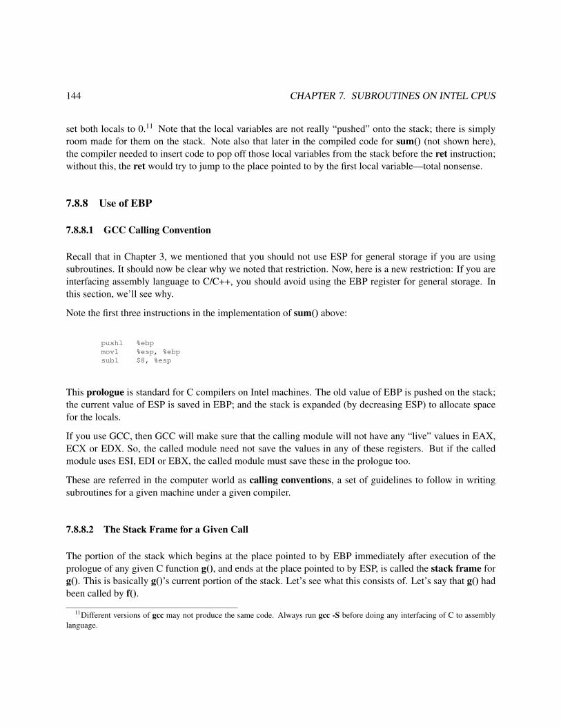
144 CHAPTER 7. SUBROUTINES ON INTEL CPUS
set both locals to 0.11 Note that the local variables are not really “pushed” onto the stack; there is simplyroom made for them on the stack. Note also that later in the compiled code for sum() (not shown here),the compiler needed to insert code to pop off those local variables from the stack before the ret instruction;without this, the ret would try to jump to the place pointed to by the first local variable—total nonsense.
7.8.8 Use of EBP
7.8.8.1 GCC Calling Convention
Recall that in Chapter 3, we mentioned that you should not use ESP for general storage if you are usingsubroutines. It should now be clear why we noted that restriction. Now, here is a new restriction: If you areinterfacing assembly language to C/C++, you should avoid using the EBP register for general storage. Inthis section, we’ll see why.
Note the first three instructions in the implementation of sum() above:
pushl %ebpmovl %esp, %ebpsubl $8, %esp
This prologue is standard for C compilers on Intel machines. The old value of EBP is pushed on the stack;the current value of ESP is saved in EBP; and the stack is expanded (by decreasing ESP) to allocate spacefor the locals.
If you use GCC, then GCC will make sure that the calling module will not have any “live” values in EAX,ECX or EDX. So, the called module need not save the values in any of these registers. But if the calledmodule uses ESI, EDI or EBX, the called module must save these in the prologue too.
These are referred in the computer world as calling conventions, a set of guidelines to follow in writingsubroutines for a given machine under a given compiler.
7.8.8.2 The Stack Frame for a Given Call
The portion of the stack which begins at the place pointed to by EBP immediately after execution of theprologue of any given C function g(), and ends at the place pointed to by ESP, is called the stack frame forg(). This is basically g()’s current portion of the stack. Let’s see what this consists of. Let’s say that g() hadbeen called by f().
11Different versions of gcc may not produce the same code. Always run gcc -S before doing any interfacing of C to assemblylanguage.

7.8. INTERFACING C/C++ TO ASSEMBLY LANGUAGE 145
From the prologue code, we can see that the beginning of g()’s frame will consist of the saved value that hadbeen in EBP before the call to g(). Well, that was the address of the beginning of f()’s stack frame! So, wesee that the first element in g()’s frame will be a pointer to f()’s frame (which of course is at higher addressesthan g()’s).
We also see that g()’s stack frame will contain g()’s local variables. And if g() saves some other registervalues on the stack, to protect f(), those will be part of g()’s frame too.
During the time g() is executing, the end of g()’s stack frame is pointed to by ESP. However, if g() in turnmakes a call to some other function, say h(), that function will also have a stack frame, at lower addressesthan g()’s frame. However, As g() executes, this position may move. This can occur for instance, if g()does call another function, say h(). ESP will decrease due to expansion of the stack by the called function’sarguments and return address, which are considered part of g()’s stack frame, not h()’s. Here is what g()’sstack frame (and a bit of f()’s and h()’s) will consist of, just after the CALL is executed but before h()’sprologue begins executing:
address in f() to return to when g() is done (end of f()’s frame)EBP→ address of f()’s stack frame (start of g()’s frame)
g()’s first declared local variableg()’s second declared local variable...g()’s last declared local variableany stack space g() is currently using as ”scratch area”last argument in g()’s call to h()...second argument in g()’s call to h()first argument in g()’s call to h()
ESP→ address in g() to return to when h() is done (end of g()’s frame)address of g()’s stack frame (start of h()’s frame)
towards 0 ↓
Of course, after we execute h()’s prologue, ESP will change again, and will demarcate the end of h()’s stackframe (and EBP will demarcate the beginning of that frame). Once h() finishes execution, the stack willshrink back again, and ESP will increase and demarcate the end of g()’s frame again.
7.8.8.3 The Stack Frames Are Chained
An implication of the structure depicted above is that in any function’s stack frame, the first (i.e. highest-address) element will contain a pointer to the beginning of the caller’s stack frame. In that sense, thebeginning elements of the various stack frames form a linked list, enabling one to trace through the stackinformation in a chain of nested calls. And since we know that EBP points to the current frame, we can usethat as our starting point in traversing this chain.

146 CHAPTER 7. SUBROUTINES ON INTEL CPUS
The authors of GDB made use of this fact when they implemented GDB’s bt (“backtrace”) command. Let’sreview that command. Consider the following example:
1 void h(int *w)2 { int z;3 *w = 13 * *w;4 }5
6 int g(int u)7 { int v;8 h(&u);9 v = u + 12;
10 return v;11 }12
13 main()14 { int x,y;15 x = 5;16 y = g(x);17 }
Let’s execute it in GDB:
(gdb) b hBreakpoint 1 at 0x804833a: file bt.c, line 3.(gdb) rStarting program: /root/50/a.out
Breakpoint 1, h (w=0xfef5d2ac) at bt.c:33 *w = 13 * *w;(gdb) bt#0 h (w=0xfef5d2ac) at bt.c:3#1 0x08048360 in g (u=5) at bt.c:8#2 0x0804839c in main () at bt.c:16
We are now in h() (shown as frame 0 in the bt output), having called it from location 0x08048360 in g()(frame 1), which in turn had been called from location 0x0804839c in main() (frame 2).
And GDB allows us to temporarily change our context to another frame, say frame 1, and take a look around:
(gdb) f 1#1 0x08048360 in g (u=5) at bt.c:88 h(&u);(gdb) p u$1 = 5(gdb) p v$2 = 0
Make sure you understand how GDB—which, remember, is itself a program—is able to do this. It does itby inspecting the stack frames of the various functions, and the way it gets from one frame to another within

7.8. INTERFACING C/C++ TO ASSEMBLY LANGUAGE 147
the stack is by the fact that the first element in a function’s stack frame is a pointer to the first element of thecaller’s stack frame.
By using the structure shown above, the compiler is ensuring that we will always be able to get to returnaddresses, arguments and so on of “ancestral” calls.
7.8.8.4 ENTER and LEAVE Instructions
We’ve noted before that after return from a function call, the caller should clean up the stack, i.e. removethe arguments it had pushed onto the stack before the call. Similarly, within the function itself there shouldbe a cleanup, to remove the locals and make sure that EBP is adjusted properly. That means: restoring ESPand EBP to the values they had before the prologue:
movl %ebp, %esppopl %ebp
Let’s call this the “epilogue.” The prologue and epilogue codes are some common that Intel included ENTERand LEAVE instructions in the chip to do them. The above prologue, a three-instruction sequence which set8 bytes of space for the locals, would be done, for instance, by the single instruction
enter 8, 0
(The 0 is never used in flat memory mode.)
The two-instruction epilogue above can be done with the single instruction
leave
Currently GCC uses LEAVE but not ENTER. The latter actually turns out to be slower on modern machinesthan just using the original three-instruction sequence, so it isn’t used anymore.
7.8.8.5 Application of Stack Frame Structure
The following code implements a “backtrace” like GDB’s. A user program calls getchain(), which willreturn a list of the return addresses of all the current stack frames. It is required that the user program firstcall the function initbase(), which determines the address of main()’s stack frame and stores it in base. It isassumed that getchain() will not be called from main() itself.
The C prototype is

148 CHAPTER 7. SUBROUTINES ON INTEL CPUS
void getchain(int *chain, int *nchain)
with the space for the array chain and its length nchain provided by the caller.
In reading the code, keep in mind this picture of the stack after the three pushes are done:
address of nchainaddress of chainsaved return address from getchain() back to the callersaved EAXsaved EBX
ESP→ saved ECXtowards 0 ↓
1 .data2 base: # address of main()’s stack frame3 .long 04
5 .text6 .globl initbase, getchain7 initbase: # initializes base8 movl %ebp, base9 ret
10 getchain:11 # register usage:12 # EAX will point to the current element of chain to be filled13 # EBX will point to the frame currently being examined14 push %eax15 push %ebx16 push %ecx17 # get address of chain18 movl 16(%esp), %eax19 # get return address from this subroutine, getchain()20 movl 12(%esp), %ecx21 # write it to the first element of the chain22 movl %ecx, (%eax)23 addl $4, %eax24 # EBP still points to the caller’s frame, perfect since we don’t want25 # to include the frame for this subroutine26 movl %ebp, %ebx27 # loop through all the frames28 top:29 # if this is main()’s frame, then done so leave30 cmpl %ebx, base31 jz done32 # get return address for this frame33 movl 4(%ebx), %ecx34 # write it to chain35 movl %ecx, (%eax)36 addl $4, %eax37 # go to next frame38 movl (%ebx), %ebx39 jmp top

7.8. INTERFACING C/C++ TO ASSEMBLY LANGUAGE 149
40 done:41 # find nchain, by subtracting start of chain from EAX and adjusting42 subl 16(%esp), %eax43 shrl $2, %eax44 movl 20(%esp), %ebx45 movl %eax, (%ebx)46 pop %ecx47 pop %ebx48 pop %eax49 ret
Example of calls:
1 int chain[5],nchain;2
3 void h(int *w)4 { int z;5 int chain[10],nchain;6 z = *w +28;7 getchain(chain,&nchain);8 *w = 13 * z;9 }
10
11 int g(int u)12 { int v;13 h(&u);14 v = u + 12;15 getchain(chain,&nchain);16 return v;17 }18
19 main()20 { int x,y;21 initbase();22 x = 5;23 y = g(x);24 }
7.8.9 The LEA Instruction Family
The name of the LEA instruction family stands for Load Effective Address. Its action is to compute thememory address of the first operand, and store that address in the second.
For example, the instruction
leal -4(%ebp), %eax
computes -4 + c(EBP) and places the result in EAX. If we had a single local variable z within a C function,the above instruction would be computing &z and placing it in EAX. The compiler often uses this technique.

150 CHAPTER 7. SUBROUTINES ON INTEL CPUS
7.8.10 The Function main() IS a Function, So It Too Has a Stack Frame
It’s important to keep in mind that main() is a function too, so it has information stored on the stack. Recallthat a typical declaration of main() is
int main(int argc, char **argv)
This clearly shows that main() is a function. Note that we’ve given main() an int return value, typicallyused as a success code, again illustrating the fact that main() is a function.
Let’s take a closer look. When you compile your program, the compiler (actually linker) puts in some Clibrary code which is used for startup. Just like your assembly language programs, there is a label there,start, at which execution begins. The code there will prepare the stack, including the argc and argv
arguments, and will then call main().
Note by the way that we are not required to give these formal parameters the names argc and argv. It ismerely customary. As a veteran C programmer, you know that you can name the formal parameters whateveryou want. When any subroutine is called, the caller, in this case the C library startup code, neither knowsnor cares what the names of the formal parameters are in the module in which the subroutine is defined.
Accordingly, upon entry to main(), the stack will consist of the return address, then argc, then argv, andspace will be made on the stack for any local variables main() may have. To illustrate that, consider thecode
1 main(int argc, char **argv)2 { int i;3 printf("%d %s\n",argc,argv[1]);4 }
After applying gcc -S to this, we get
1 .file "argv.c"2 .section .rodata3 .LC0:4 .string "%d %s\n"5 .text6 .align 27 .globl main8 .type main,@function9 main:
10 pushl %ebp11 movl %esp, %ebp12 subl $8, %esp13 andl $-16, %esp14 movl $0, %eax15 subl %eax, %esp

7.8. INTERFACING C/C++ TO ASSEMBLY LANGUAGE 151
16 subl $4, %esp17 movl 12(%ebp), %eax18 addl $4, %eax19 pushl (%eax)20 pushl 8(%ebp)21 pushl $.LC022 call printf23 addl $16, %esp24 leave25 ret26 .Lfe1:27 .size main,.Lfe1-main28 .ident "GCC: (GNU) 3.2 20020903 (Red Hat Linux 8.0 3.2-7)"
We see that argc and argv are 8 and 12 bytes from EBP, respectively. This makes sense, since from Section7.8.8 we know that upon entry to main(), the stack headed by the place pointed to by EBP will look likethis:
argvargcreturn addresssaved EBP
At the end of main(), the GCC compiler will put the return value in EAX, and will produce a LEAVEinstruction.
Let’s look at this from one more angle, by running this program via GDB:
1 % gcc -S argv.c2 % as --gstabs -o argv.o argv.s3 % gcc -g argv.o4 % gdb -q a.out5 (gdb) b 106 Breakpoint 1 at 0x8048328: file argv.s, line 10.7 (gdb) r abc def8 Starting program:9 /fandrhome/matloff/public_html/matloff/public_html/50/PLN/a.out abc def
10
11 Breakpoint 1, main () at argv.s:1012 10 pushl %ebp13 Current language: auto; currently asm14 (gdb) x/3x $esp15 0xbfffe33c: 0x42015967 0x00000003 0xbfffe38416 (gdb) x/3x 0xbfffe38417 0xbfffe384: 0xbfffe95c 0xbfffe99c 0xbfffe9a018 (gdb) x/s 0xbfffe95c19 0xbfffe95c:20 "/fandrhome/matloff/public_html/matloff/public_html/50/PLN/a.out"21 (gdb) x/s 0xbfffe99c22 0xbfffe99c: "abc"23 (gdb) x/s 0xbfffe9a024 0xbfffe9a0: "def"

152 CHAPTER 7. SUBROUTINES ON INTEL CPUS
So we see that the return address to the C library is 0x42015967, argc is 3 and argv is 0xbfffe384. The lattershould be a pointer to an array of three strings, which is confirmed in the subsequent GDB commands.
By the way, the instruction
andl $-16, %esp
forces the top of the stack to be located at an address which is a multiple of 16. (It zeros out the last 4 bits.)The hardware structure makes memory accesses at such addresses most efficient.
By the way, the C library code provides a third argument to main() as well, which is a pointer to the envi-ronment variables (current working directory, executable search path, username, etc.). Then the declarationwould be
int main(int argc, char **argv, char **envp)
7.8.11 Once Again, There Are No Types at the Hardware Level!
You have been schooled—properly so—in your beginning programming classes about the importance ofscope, meaning which variables are accessible or inaccessible from which parts of a program. But if avariable is inaccessible from a certain point in a program, that is merely the compiler doing its gatekeeperwork for that language. It is NOT a restriction by the hardware. There is no such thing as scope at thehardware level. ANY instruction in a program—remember, all C/C++ and assembly code gets translated tomachine instructions—can access ANY data item ANYWHERE in the program.
In C++, you were probably taught a slogan of the form
“A private member of a class cannot be accessed from anywhere outside the class.”
But that is not true. The correct form of the statement should be
“The compiler will refuse to compile any C++ code you write which attempts to access by namea private member of a class from anywhere outside the class.”
Again, the gatekeeper here is the compiler, not the hardware. The compiler’s actions are desirable, becausethe notion of scope helps us to organize our data, but it has no physical meaning. Consider this example:
1 #include <iostream.h>2
3 class c {

7.8. INTERFACING C/C++ TO ASSEMBLY LANGUAGE 153
4 private:5 int x;6 public:7 c(); // constructor8 // printx() prints out x9 void printx() { cout << x << endl; }
10 };11
12 c::c()13 { x = 5; }14
15 int main(int argc, char *argv[])16 { c ci;17 ci.printx(); // prints 518 // now point p to ci, thus to the first word at ci, i.e. x19 int *p = (int *) &ci;20 *p = 29; // change x to 2921 ci.printx(); // prints 2922 }
The point is that the member variable x in the class c, though private, is nevertheless in memory, and wecan get to any memory location by setting a pointer variable to that location. That is what we have donein this example. We’ve managed to change the value of x in an instance of the class through code which isoutside the class.
The point alos applies to local variables. We can actually access a local variable in one function from codein another function. The following example demonstrates that (make sure to review Section 7.8.8 beforereading the example):
1 void g()2 { int i,*p;3 p = &i;4 p = p + 1; // p now points to main()’s EBP5 p = *p; // p now equals main()’s EBP value6 p = p - 1; // p now points to main()’s x7 *p = 29; // changes x to 298 }9
10 main()11 { int x = 5; // x is local to main()12 g();13 printf("%d\n",x); // prints out 2914 }
7.8.12 What About C++?
If the calling program is C++ instead of C, you must inform the compiler that the assembly language routineis “C style,” by inserting

154 CHAPTER 7. SUBROUTINES ON INTEL CPUS
extern "C" void addone(int *);
in the C++ source file. You need to do this, because your assembly language routine will be in the C style,i.e. utilize C conventions such as that concerning EBP above.
For instance (i.e. non-static) functions, note that the this pointer is essentially an argument too. Theconvention is that it is pushed last, i.e. it is treated as the first argument.
7.8.13 Putting It All Together
To illustrate a number of the concepts we’ve covered here, let’s look at the full assembly code producedfrom the function sum() in Section 7.8.7. Here is the original C and then the compiled code:
1 int sum(int *x, int n)2 { int i=0,s=0;3
4 for (i = 0; i < n; i++)5 s += x[i];6 return s;7 }
1 .file "sum.c"2 .text3 .align 24 .globl sum5 .type sum,@function6 sum:7 pushl %ebp8 movl %esp, %ebp9 subl $8, %esp
10 movl $0, -4(%ebp)11 movl $0, -8(%ebp)12 movl $0, -4(%ebp)13 .L2:14 movl -4(%ebp), %eax15 cmpl 12(%ebp), %eax16 jl .L517 jmp .L318 .L5:19 movl -4(%ebp), %eax20 leal 0(,%eax,4), %edx21 movl 8(%ebp), %eax22 movl (%eax,%edx), %edx23 leal -8(%ebp), %eax24 addl %edx, (%eax)25 leal -4(%ebp), %eax26 incl (%eax)27 jmp .L228 .L3:29 movl -8(%ebp), %eax

7.8. INTERFACING C/C++ TO ASSEMBLY LANGUAGE 155
30 leave31 ret32 .Lfe1:33 .size sum,.Lfe1-sum34 .ident "GCC: (GNU) 3.2 20020903 (Red Hat Linux 8.0 3.2-7)"
We see that the compiler has first placed the standard prologue at the beginning of the code, allowing fortwo local variables:
1 sum:2 pushl %ebp3 movl %esp, %ebp4 subl $8, %esp
It then initializes both of those locals to 0.
1 movl $0, -4(%ebp)2 movl $0, -8(%ebp)
Since our code sets i to 0 twice, the compiler does so too, since we didn’t ask the compiler to optimize.
Our for loop compares i to n, which is done here:
1 movl -4(%ebp), %eax2 cmpl 12(%ebp), %eax3 jl .L54 jmp .L3
The code must add x[i] to the sum:
1 .L5:2 movl -4(%ebp), %eax3 leal 0(,%eax,4), %edx4 movl 8(%ebp), %eax5 movl (%eax,%edx), %edx6 leal -8(%ebp), %eax7 addl %edx, (%eax)
Note the use of the LEA instruction and advanced addressing modes.
We need to increment i and go to the top of the loop:
1 leal -4(%ebp), %eax2 incl (%eax)3 jmp .L2

156 CHAPTER 7. SUBROUTINES ON INTEL CPUS
When the function is finished, it needs to put the sum in EAX, as described in Section 7.8.5, clean up thestack and return:
1 .L3:2 movl -8(%ebp), %eax3 leave4 ret
Note the use of the LEAVE instruction.
Now, what if we declare that local variable s as static?
1 int sum(int *x, int n)2 { int i=0; static s=0;3
4 for (i = 0; i < n; i++)5 s += x[i];6 return s;7 }
Recall that this means that the variable will retain its value from one call to the next.12 That means that thecompile can’t use the stack for storage of this variable, as it would likely get overwritten by calls from othersubroutines. So, it must be stored in a .data section:
1 .file "Sum.c"2 .data3 .align 44 .type s.0,@object5 .size s.0,46 s.0:7 .long 08 .text9 .align 2
10 .globl sum11 .type sum,@function12 sum:13 pushl %ebp14 movl %esp, %ebp15 subl $4, %esp16 movl $0, -4(%ebp)17 movl $0, -4(%ebp)18 .L2:19 movl -4(%ebp), %eax20 cmpl 12(%ebp), %eax21 jl .L522 jmp .L323 .L5:24 movl -4(%ebp), %eax
12Our code initializes s to 0, but this is done only once, as you can see from the assembly language here.

7.9. SUBROUTINE CALLS/RETURNS ARE “EXPENSIVE” 157
25 leal 0(,%eax,4), %edx26 movl 8(%ebp), %eax27 movl (%eax,%edx), %eax28 addl %eax, s.029 leal -4(%ebp), %eax30 incl (%eax)31 jmp .L232 .L3:33 movl s.0, %eax34 leave35 ret36 .Lfe1:37 .size sum,.Lfe1-sum38 .ident "GCC: (GNU) 3.2 20020903 (Red Hat Linux 8.0 3.2-7)"
You can tell from the code
movl s.0, %eaxleaveret
that our C variable s is being stored at a label s.0 in the .data section.
7.9 Subroutine Calls/Returns Are “Expensive”
On most machines, subroutine calls and returns add overhead. Not only does it mean that extra instructionsmust be executed, but also stack access, being memory access, is slow. So, it makes sense to ask how CPUscould be designed to speed this up.
One approach would be to make a special cache for the stack. Note that since the stack is in memory, someof it may be in an ordinary cache, but by devoting a special cache to the stack, we would decrease the cachemiss rate for the stack.
But a more aggressive approach would be to design the CPU so that the top few stack elements are in theCPU itself. This is done in Sun Microsystems’ SPARC chip, and was done back in the 60s and 70s onBurroughs mainframes. This would be better than a special cache, since the latter, with its complex circuitryfor miss processing and so on, would have more delay.
On the other hand, space on a chip is precious. It may be that such usage of the space may not be as good assome other usage.

158 CHAPTER 7. SUBROUTINES ON INTEL CPUS
7.10 Debugging Assembly Language Subroutines
7.10.1 Focus on the Stack
At first, debugging assembly language subroutines would seem to be similar to debugging assembly lan-guage in general, and for that matter, debugging any kinds of code. However, what makes the assembly-language subroutine case special is the use of the stack. Many bugs involve errors in accessing the stack,such as failure to restore a register value which had been saved on the stack.
Recall that the essence of good debugging is confirmation. One uses the debugger, say ddd, to step throughone’s code line by line, and in each line confirms that our stored data (variables in C/C++, register andmemory values in assembly language) have the values we expect them to. In stepping through our code,we also confirm that we execute the lines we expect to be executed, such as a conditional branch beingtaken when we expect it to be taken. Eventually this process will lead us to a line in which we find that ourconfirmation fails. This then will pinpoint where our bug is, and we can start to analyze what is wrong withthat line.
For assembly language subroutines, our confirmation process consists of confirming that the contents of thestack are exactly as we expect them to be. Eventually we will find a line of code at which that confirmationfails, and we then will have pinpointed the location of our bug, and we can start to analyze what is wrongwith that line.
To do that, you have to know how to inspect the stack from within your debugger, e.g. ddd. The key pointis that the stack is part of memory, and the debugger allows you to inspect memory. So, first find out fromthe debugger the current value of ESP, and then inspect a few words of memory starting at wherever ESPpoints to, e.g.
x/4w $esp
to inspect the first four words of the stack in GDB.13
Note that if during a debugging session you run your program several times without exiting GDB,14 thestack will keep growing. Thus any stack addresses which you jot down for later use may become incorrect.
7.10.2 A Special Consideration When Interfacing C/C++ with Assembly Language
When you are interfacing C/C++ to assembly language and while debugging you reach a function call in yourC/C++ code, it is often useful to view the assembly language, especially the addresses of the instructions.
13You can now see an advantage of designing the hardware so that stacks grow toward 0. This causes consecutive elements ofthe stack to be in consecutive locations, making it easier to inspect the stack.
14And this is the proper way to do it. You SHOULD stay in GDB from one run to the next, so as to retain your breakpoints etc.

7.11. MACROS 159
You may find GDB’s disassemble command useful in this regard. It reverse-translates the machine codefor the program into assembly language (regardless of whether the program source was originally assemblylanguage or C/C++), and lists the assembly language instructions and their addresses. Note that the latterwill be addresses with respect to the linker’s assignments of the .text section location, not offsets as in theoutput of as -a. Also note that .data section symbols won’t appear; the actual addresses will show up.
The disassemble command has several formats. If you run it without arguments, it will disassemble thecode near your current location. You can also run it on any label in the .text section, e.g.
(gdb) disas _start
and
(gdb) disas main
In the latter case, where we have a function name, the entire function will be disassembled.
You can also specify a range of memory addresses, e.g.
(gdb) disas 0x08048083 0x08048099
7.11 Macros
Subroutines—functions, at the C/C++ level—are really good for writing one’s code in a modular manner,which is a highly laudable goal. However, they are costly in terms of performance.
A subroutine/function call involves one or more pushes onto the stack, and it involves a jump. The pushestake time, as does the jump. This causes a slowdown. And since pushes and instruction fetches involve thememory, the call increases the number of memory accesses, and thus increases the chance of a cache miss,the latter being a big blow to performance.
A macro is like a subroutine in the sense that it makes one’s programming more modular, but without suchoverhead. Instead, it is merely yet another “abbreviation” for the clerk, albeit one that makes our codemodular.
To see what this means, consider this example from Chapter 3:
1 .data2 x:3 .long 14 .long 55 .long 2

160 CHAPTER 7. SUBROUTINES ON INTEL CPUS
6 .long 187 sum:8 .long 09 .text
10 .globl _start11 _start:12 movl $4, %eax13 movl $0, %ebx14 movl $x, %ecx15 top: addl (%ecx), %ebx16 addl $4, %ecx17 decl %eax18 jnz top19 done: movl %ebx, sum
Those first three lines of executable code,
movl $4, %eaxmovl $0, %ebxmovl $x, %ecx
perform various initializations. To make our program more modular, we could make a subroutine out ofthem, say as init() in Section 7.7 (either with or without the argument). This would be fine, but it wouldslow down the execution of the program a bit, as noted above.
An alternative would be to convert those three instructions to a macro:
1 .macro init2 movl $4, %eax3 movl $0, %ebx4 movl $x, %ecx5 .endm6
7 .data8 x:9 .long 1
10 .long 511 .long 212 .long 1813 sum:14 .long 015
16 .text17 .globl _start18 _start:19 init20 top: addl (%ecx), %ebx21 addl $4, %ecx22 decl %eax23 jnz top24 done: movl %ebx, sum

7.11. MACROS 161
Though the “init” at start has the look of a subroutine call, it really isn’t. Instead, when the assembler seesthis line at start, it replaces that line with the three lines of code defined for “init” at the top of the file. Inour definition of this macro init, starting with .macro and ending with .endm, we are saying to the clerk,“Clerk, if you ever see a line in my assembly file here that consists of init, treat that as if I had typed thefollowing code at that point...”
In other words, the macro version of the program will produce exactly the same machine code as did theoriginal nonmodular version. We can see this by running both files through as -a; here are excerpts from theoutputs of this command from the original and macro versions of the program:
...23 _start:24 0000 B8040000 movl $4, %eax24 0025 0005 BB000000 movl $0, %ebx25 0026 000a B9000000 movl $x, %ecx26 0027 000f 0319 top: addl (%ecx), %ebx
...
...20 _start:21 0000 B8040000 init21 00BB000021 0000B90021 00000022 000f 0319 top: addl (%ecx), %ebx
...
So, both versions of the program would produce the same .o file. By contrast, the subroutine versionproduces different code:
...23 _start:24 0000 E80E0000 call init24 0025 0005 0319 top: addl (%ecx), %ebx
...31 init:32 0013 B8040000 movl $4, %eax32 0033 0018 BB000000 movl $0, %ebx33 0034 001d B9000000 movl $x, %ecx34 0035 0022 C3 ret
Note the machine code for the call instruction and the ret. So, by using a macro we get the efficiency of the

162 CHAPTER 7. SUBROUTINES ON INTEL CPUS
nonmodular version while still getting a modular view for the programmer.15
Macros allow arguments too. Within a macro itself, the macro’s arguments are rereferred to using back-slashes.
For example, the macro yyy has two arguments, u and v:
.macro yyy u,vmovl \u,%eaxaddl \v,%eax
.endm
So the call
yyy $5,$12
will produce the same code as we had written
movl $5, %eaxaddl $12, %eax
Similarly, the call
yyy %ebx,y
will produce the same code as we had written
movl %ebx, %eaxaddl y, %eax
Note that here we could not even use a subroutine instead of the macro, as the subroutine could not do“substitution” for us.
Since macros give us the modularizing benefit of subroutines without their performance-inhibiting overhead,why just always use macros? Here are some reasons:
• Macros make the program’s executable file larger. If we call the same macro at many different pointsin a program, we get many copies of the code.
• Debugging tools usually do not handle macros well.15Though this modular view will not appear in a debugging tool, a drawback.

7.12. INLINE ASSEMBLY CODE FOR C++ 163
• Macros cannot handle recursion.16
You can write macros in C/C++ too, e.g.
#define PRINT2INTS(i1,i2) (printf("%d %d\n",i1,i2))
main(){ PRINT2INTS(5,12); }
7.12 Inline Assembly Code for C++
The C++ language includes an asm construct, which allows you to embed assembly language source coderight there in the midst of your C++ code.17
This feature is useful, for instance, to get access to some of the fast features of the hardware. For example,say you wanted to make use of Intel’s fast MOVS string copy instruction. You could write an assemblylanguage subroutine using MOVS and then link it to your C++ program, but that would add the overhead ofsubroutine call/return. Instead, you could write the MOVS code there in your C++ source file.
Here’s a very short, overly simple example:
// file a.c
int x;
main()
{ scanf("%d",&x);__asm__("pushl x");
}
After doing
gcc -S a.c
the file a.s will be
.file "a.c"
.section .rodata
16Pointed out by Mikel McDaniel. Of course, one can do recursion “by hand,” by managing a stack with one’s own code, but thepoint is that subroutines do this automatically.
17This is, as far as I know, available in most C++ compilers. Both GCC and Microsoft’s C++ compiler allow it.

164 CHAPTER 7. SUBROUTINES ON INTEL CPUS
.LC0:.string "%d".text
.globl main.type main, @function
main:leal 4(%esp), %ecxandl $-16, %esppushl -4(%ecx)pushl %ebpmovl %esp, %ebppushl %ecxsubl $20, %espmovl $x, 4(%esp)movl $.LC0, (%esp)call scanf
#APPpushl x
#NO_APPaddl $20, %esppopl %ecx
Our assembly language is bracketed by APP and NO APP, and sure enough, it is
pushl x
For an introduction to how to use this feature, see the tutorials on the Web; just plug “inline assemblytutorial” into Google. For instance, there is one at http://www.opennet.ru/base/dev/gccasm.txt.html.

Chapter 8
Overview of Input/Output Mechanisms
8.1 Introduction
During the early days of computers, input/output (I/O) was of very little importance. Instead computers,as their name implied, were used to compute. A typical application might involve huge mathematicalcalculations needed for some problem in physics. The I/O done in such an application would be quiteminimal, with the machine grinding away for hours at a time with little or no I/O being done.
Today, I/O plays a key role in computer applications. In fact, applications in which I/O plays an importantrole can arguably be viewed as the most powerful “driving force” behind the revolutionary rise to prominenceof computers in the last decade or two. Today we make use of computers in numerous aspects of our businessand personal lives–and in the vast majority of such uses, the programs center around I/O operations.
In some of these applications, the use of a computer is fairly obvious: First and foremost, the Internet, butalso credit-card billing, airline reservations, word processors, spreadsheets, automatic teller machines, realestate databases, drafting programs for architects, video games, and so on. Possibly less obvious is theexistence of computers in automobiles, and in such household items as washing machines and autofocuscameras. However, whether the existence of computers in these applications is obvious or hidden, thecommon theme behind them is that they all are running programs in which I/O plays an importantrole, usually the dominant role.
To give some concrete of the central role played by I/O, consider the example of the ATM machine. Hereare some of the I/O devices the computer in the machine will have:
• The motor used to drag the card in and push it out.
• The scanner which reads the magnetic strip on the card.
165

166 CHAPTER 8. OVERVIEW OF INPUT/OUTPUT MECHANISMS
• The motors used to prepare and push out the cash.
• The screen and keypad.
• The connection to the network (which leads to a central computer for the bank chain).
8.2 I/O Ports and Device Structure
An I/O device connects to the system bus through ports. I/O ports are similar in structure to CPU registers.However, a port is not in the CPU, being instead located between the I/O device and the system bus, in theinterface card for the device.
Ports are usually 8 bits in width. They have addresses, just like words in memory do, and these addressesare given meaning through the address bus, just as is the case for words in memory.
8.3 Program Access to I/O Ports
Note that a potential ambiguity arises. Suppose we wish to communicate with port 50, which is connectedto some I/O device. The CPU will place the value 50 in the MAR to go out onto the address bus. Since allitems which are connected to the bus will see what is on the address bus, how can they distinguish this 50,intended for an I/O port, from a value of 50 meant to address 50 of memory? In other words, how can theCPU indicate that it wants to address I/O port 50 rather than memory word 50? There are two fundamentalsystems for handling this problem, described next.
8.3.1 I/O Address Space Approach
Recall that the system bus of a computer consists of an address bus, a data bus, and a control bus. Thecontrol bus in many computers, such as those based on Intel CPUs, has a special line or lines to indicate thatthe current value on the address bus is meant to indicate an I/O port, rather than a word in memory. We willassume four such lines, MR (memory read), MW (memory write), IOR (I/O read) and IOW (I/O write).
To access I/O port 50, the CPU will assert either IOR or IOW (depending on whether it wants to read fromor write to that port), while to access word 50 in memory, the CPU will assert either MR or MW. In eithercase the CPU will place the value 50 on the address bus, but the values it simultaneously places on theselines in the control bus will distinguish between I/O port 50 and word 50 of memory.
The programmer himself or herself controls which of these lines will be asserted, by choosing which in-struction to use.

8.3. PROGRAM ACCESS TO I/O PORTS 167
movb 50, %al
and
inb $50, %al
will both cause the value 50 to go out onto the address bus, and in both cases the response will be sent backvia the data bus. But the MOV will assert the MR line in the control bus, while the IN instruction will assertthe IOR line in that bus. As a result, the MOV will result in copying the memory byte at address 50 to AL,while the IN will copy the byte from I/O port 50 to AL.1
Since the lines IOR/IOW and MR/MW allow us to distinguish between I/O ports and memory words havingidentical addresses, we can describe this by saying that the I/O ports have a separate address space fromthat of memory. Thus we will call this the I/O address space approach.
Note the profound hardward dependency here. The asserting of IOR/IOW or MR/MW comes from usingIN/OUT or MOV, respectively, and thus the machine must have such instructions.
8.3.2 Memory-Mapped I/O Approach
Another approach to the “duplicate port/memory address” problem described above is called memory-mapped I/O.”2
Under this approach, there are no special lines in the control bus to indicate I/O access versus memory access(though there still must be one or two lines to distinguish a read from a write, of course), and thus no specialI/O instructions such as IN and OUT. One simply uses ordinary instructions such as MOV, whether one isaccessing I/O ports or memory. Of course, the people who put the computer together must avoid placingmemory at the addresses used by I/O ports.
An advantage of memory-mapped I/O is that it can be done directly in C, e.g.:
char c,*p;...p = 50;c = *p;
Say c and p were global variables. Then the compiler will likely translate the line1You may wonder why the dollar sign is needed in the second instruction, which seems inconsistent with that of the first
instruction. But this comes from Intel tradition, so we are stuck with it.2Unfortunately, many terms in the computer field are “overloaded.” It has become common on personal computers to refer to
the mapping of video monitor pixels to memory addresses also as “memory-mapped I/O.” However, this is not the original use ofthe term, and should not be confused with what we are discussing here.

168 CHAPTER 8. OVERVIEW OF INPUT/OUTPUT MECHANISMS
c = *p;
to something like
movl p, %ebxmovb (%ebx), %almovb %al, c
So you can see that from the CPU’s point of view, reading that I/O port, which is done by the instructions
movb (%ebx), %al
is the same as reading from memory. Indeed, the CPU is not aware of the fact that we are reading from anI/O port, which has a very different operation and physical structure from memory.
8.4 Wait-Loop I/O
Consider the case of reading a character from the keyboard. The program which will read the character hasno idea when the user will hit a key on the keyboard. How should the program be written to deal with thistime problem? (Note that we are for the moment discussing programs which directly access the keyboard,rather than going through the operating system, as is the case with programs you usually write; more on thispoint later.)
On an Intel-based PC, the keyboard data port (KDP) has address 0x60, and its status port (KSP) is at 0x62.Among other things, the KSP tells us whether a key has been typed yet; Bit 4 will be 1 if so, 0 otherwise.3
Bit 5 of the KSP plays a role too. When we read the character, we have to notify the keyboard hardware thatwe’ve gotten it, so that it can give us another character when one is typed. To do this, we briefly set Bit 5 to1 and then back to 0. This will cause Bit 4 of the KSP to revert to 0 too.
Wait-loop I/O then consists of writing a loop, in which the program keeps testing Bit 4 of the KSP untilthat bit indicates “character ready,” and then read the character from KDP into some register:4
1 # loop around until a character is ready2 lp:3 inb $0x62, %bl # get value of KSP4 andb $0x10, %bl # check Bit 45 jz lp # if that bit is 0, try again6 ready:
3As usual, we are naming the least significant bit “Bit 0,” etc.4By the way we won’t have the character in ASCII form. Instead, we will have it as a scan code. More on this below.

8.5. PC KEYBOARDS 169
7 # get the character8 inb $0x60, %cl9 # acknowlege getting the character
10 # set Bit 5 of KSP to 111 orb $0x20, %bl12 outb %bl, $0x6213 # reset Bit 5 of KSP to 014 andb $0xdf, %bl15 outb %bl, $0x6216 done:
During the time before the user hits a key, the value read from the KSP will always have a 0 in Bit 4, so thatthe AND results in 0, and we jump back to lp. But eventually the user will hit a key, resulting in Bit 4 ofthe KSP being 1, and we leave the loop. We then pick up the character in the code starting at done.
8.5 PC Keyboards
On Intel- (or Intel clone-) based PCs, the keyboard is not directly wired for ASCII. Instead, each of the keyshas its own scan code—actually two codes, one which the keyboard emits when a key is pressed and theother, 128 more than the first code, which the keyboard emits when the key is released. For example, the Akey has codes 0x1e and 0x9e, respectively. The keyboard driver will then convert to ASCII.
Say for instance that the user wishes to type ‘A’, i.e. the capital letter. She may hit the left Shift key (code0x2a), then hit the A key (code 0x1e), then release the A key (code 0x9e) then release the left Shift key(code 0xaa). The keyboard driver can be written to notice that when the A key is hit, the Shift key has notyet been released, and thus the user must mean a capital ‘A’. The driver then produces the ASCII code 0x41.
8.6 Interrupt-Driven I/O
8.6.1 Telephone Analogy
Wait-loop I/O is very wasteful. Usually the speed of I/O device is very slow compared to CPU speed. Thisis particularly true for I/O devices which are mainly of a mechanical rather than a purely electronic nature,such as printers and disk drives, and thus are usually orders of magnitude slower than CPU actions. It iseven worse for a keyboard: Not only is human typing extremely slow relative to CPU speeds, but also a lotof the time the user is not typing at all; he/she may be thinking, taking a break, or whatever.
Accordingly, if we use wait-loop I/O, the CPU must execute the wait loop many times between successiveI/O actions. This is wasted time and wasted CPU cycles.
An analogy is the following. Suppose you are expecting an important phone call at the office. Imagine howwasteful it would be if phones didn’t have bells—-you would have to repeatedly say, “Hello, hello, hello, ...”

170 CHAPTER 8. OVERVIEW OF INPUT/OUTPUT MECHANISMS
into the phone until the call actually came in! This would be a big waste of time. The bell in the phone freesyou from this; you can do other things around the office, without paying attention to the phone, because thebell will notify you when a call arrives.
Thus it would be nice to have an analog of a telephone bell in the computer. This does exist, in the form ofan interrupt. It takes the form of a pulse of current sent to the CPU by an I/O device. This pulse forces theCPU to suspend, i.e. “interrupt,” the currently-running program, say “X,” and switch execution to anotherprocedure, which we term the interrupt service routine (ISR) for that I/O device.5
The ISR is usually is known as the device driver for that I/O device. It is typically part of the operatingsystem, but it of course exists on systems without an OS too.
8.6.2 What Happens When an Interrupt Occurs?
Think for example of the keyboard or any other I/O device which receives characters.
There will be an interrupt request line (IRQ) in the control bus. When an I/O device receives a character, itwill assert IRQ.
Recall that we have described the CPU as repeatedly doing Step A, Step B, Step C, Step A, Step B, etc.where Step A is instruction fetch, Step B is instruction decode, and Step C is instruction execution. Well,in addition, the CPU will check the IRQ line after every Step C it does. If it sees IRQ asserted, it will do aStep D, consisting of the following in the Intel case:
CPU pushes current EFLAGS value on stackCPU pushes current CS value on stack (irrelevant in 32-bit protected mode)CPU pushes current PC value on stackCPU does PC <-- ISR addresss
The next Step A will, as usual, fetch from wherever the PC points, which in this case will be the ISR. TheISR will start executing.
At the end of the ISR there will be an IRET (“interrupt return”) instruction, which “undoes” all of this:
CPU pops stack and placed popped value into PCCPU pops stack and placed popped value into CSCPU pops stack and placed popped value into EFLAGS
Say this occurs when persons X and Y are both using this machine, say X at the console and Y remotelyvia ssh. X’s and Y’s programs take turns using the machine (details in Chapter 9). Say during Y’s turn,
5This is called a hardware interrupt or external interrupt. Those who have done prior assembly-language programming onPCs should not confuse this with the INT instruction. The latter is almost the same as a procedure CALL instruction, and is usedon PCs to implement systems calls, i.e. calls to the operating system.

8.6. INTERRUPT-DRIVEN I/O 171
X types a character. That causes an interrupt, which will be noticed by the CPU when it finishes Step C ofwhatever instruction in Y’s program it had been executing when X hit the key.
From the above description, you can see that the CPU will make a sudden jump to the ISR, so Y’s programwill stop running. But the hardware saves the current PC and EFLAGS values of Y’s program on the stack,so that Y’s program can resume later in exactly the same conditions it had at the time it was interrupted.Note carefully that all of that will be done by the hardware, without a single instruction being executed.
The IRET instruction at the end of the ISR is what restores those conditions. Note for instance that it iscrucial that Y’s EFLAGS value be restored. If for example Y was in the midst of executing the first of thepair of instructions
subl %eax, %ebxjz x
execution of the second, which will occur when Y’s program resumes, will check whether the Z (Zero) flagin EFLAGS had been set by the SUB instruction. So, EFLAGS must be saved by the CPU when the interruptoccurs, and restored by the IRET.
Make absolutely SURE you understand that the jump to the ISR did NOT occur from a jump or call instruc-tion in Y’s program. Y did nothing to cause that jump. However, the jump back to Y did occur because theOS programmer put an IRET at the end of the ISR.
Note too what happens if Y hits a key while X’s program is running. That will cause an interrupt to be feltat Y’s CPU, which will result in it sending the character through the network, eventually ending up in theEthernet data port of the machine where X is–causing an interrupt on THAT machine.
8.6.3 Alternative Designs
By the way, note that when an interrupt occurs, the CPU doesn’t even see it until it finishes Step C ofwhatever instruction was executing at the time the INTR line was asserted. It could be designed differently,by setting up the circuitry so that instructions would be inerruptible in the middle. That would reduceinterrupt response time a bit, which is good, but at a great expense in complexity. Not only would thecircuitry have to save the values of the EFLAGS, CS and PC registers on the stack, but it would also haveto save information as to just how much of the instruction had been executed at the time it was interrupted.That would be a lot of extra design work, for rather little performance benefit.
However, in the Intel case, they did make one concession to this idea, in the case of the MOVS instructionfamily. A MOVS instruction may take so long to execute that it is worth interrupting in the middle, and theIntel engineers did design it this way.

172 CHAPTER 8. OVERVIEW OF INPUT/OUTPUT MECHANISMS
8.6.4 Glimpse of an ISR
Here is what a simple keyboard ISR might look like, assuming we wish to store the character at a labelkeybdbuf in memory:
1 # save interrupted program’s EAX and EBX2 pushl %eax3 pushl %ebx4 # get character5 inb $0x60, %al6 # copy it to the keyboard buffer7 movb %al, keybdbuf8 # acknowlege getting the character9 inb $0x62, %bl
10 orb $0x20, %bl11 outb %bl, $0x6212 andb $0xdf, %bl13 outb %bl, $0x6214 # restore interrupted program’s EAX, EBX values15 popl %ebx16 popl %eax17 # back to the interrupted program18 iret
The OS/ISR is not running when the interrupt occurs. The key point is that at some times (whenever someonehits a key, in this case) the ISR will need to be run, and from the point of view of the interrupted program,that time is unpredictable. In the example here, each time a character is typed, a different instruction withinthe program might get interrupted.
8.6.5 I/O Protection
Linux runs the Intel CPU in flat protected mode, which sets 32-bit addressing and enables the hardwareto provide various types of security features needed by a modern OS, such as virtual memory. Again forsecurity reasons, we want I/O to be performed only by the OS. The Intel CPU has several modes of operation,which we will simplify here to just User Mode and Kernel (i.e. OS) Mode. The hardware is set up so thatI/O instructions such as IN and OUT can be done only in Kernel Mode, and that an interrupt causes entry toKernel Mode.6
6By setting a special flag in EFLAGS, the OS can allow user programs to execute IN and OUT for specified devices.

8.6. INTERRUPT-DRIVEN I/O 173
8.6.6 Distinguishing Among Devices
8.6.6.1 How Does the CPU Know Which I/O Device Requested the Interrupt?
Each I/O device is assigned an ID number, known colloquially as its “IRQ number.” In PCs, typcally the8253 timer has IRQ 0, the keyboard has IRQ 1, the mouse IRQ 12, and so on.
After the I/O device asserts the IRQ line in the bus and the CPU notices, the CPU will then assert the INTA,Interrupt Acknowledge, line in the bus. That assertion is basically a query from the CPU to all the I/Odevices, saying, “Whoever requested the interrupt, please identify yourself.” The requesting I/O device thensends its ID number (e.g. 1 in the case of the keyboard) to the CPU along the data lines in the bus, so thatthe CPU knows that it was device 1 that requested the interrupt.
8.6.6.2 How Does the CPU Know Where the ISR Is?
The Intel CPU, like many others, uses vectored interrupts. Each I/O device will have its own “vector,”which consists of a pointer to the I/O device’s ISR in memory, plus some additional information.7 Thepointer and the additional information comprise the “vector” for this I/O device.
All the vectors are stored in an interrupt vector table in memory, a table which the OS fills out upon bootup.Each vector is 8 bytes long, so the vector for I/O device i is located at c(IDT)+8*i, where c() means “contentsof.” The CPU has an Interrupt Descriptor Table register, IDT. Upon bootup, the OS will point this registerto the beginning of the table. So for example, upon bootup, the OS initializes the first 4 bytes at c(IDT)+8to point to the OS’s keyboard device driver (ISR).
Note the hardware/software interaction here: The CPU hardware is what reacts to the interrupt, but the placethat the CPU jumps to was specified by the software, i.e. the OS, in the interrupt vector table in memory.The ISR is of course also software.
8.6.6.3 Revised Interrupt Sequence
We now see that we have to expand the description in Section 8.6.2 of what the circuitry does when aninterrupt occurs:
CPU pushes current EFLAGS value on stackCPU pushes current CS value on stack (irrelevant in 32-bit protected mode)CPU pushes current PC value on stackCPU asserts INTA lineCPU reads i from data bus
7One piece of such “additional information” is the mode in which the ISR is to be run, which typically will be set to KernelMode. Later, when the ISR ends by executing an IRET instruction, the mode of the interrupted program will be restored.

174 CHAPTER 8. OVERVIEW OF INPUT/OUTPUT MECHANISMS
CPU computes j = c(IDT)+8*iCPU reads location j+4, sets interrupt hardware optionsCPU reads location j; let k = c(j)CPU does PC <-- k
8.6.7 How Do PCs Prioritize Interrupts from Different Devices?
Interrupt systems can get quite complex. What happens, for example, when two I/O devices both issueinterrupts at about the same time? Which one gets priority? Similarly, what if during execution of the ISRfor one device, another device requests an interrupt? Do we suspend the first ISR, i.e. give priority to thesecond?
To deal with this problem, PCs also includes another piece of Intel hardware, the Intel 8259A interruptcontroller chip. The I/O devices are actually connected to the 8259A, which in turn is connected to the IRQ(Interrupt Request) line, instead of the devices being connected directly to the IRQ. The 8259A has manyinput pins, one for each I/O device.8 So, the 8259A acts as an “agent,” sending interrupt requests to the CPU“on behalf of” the I/O devices.
If several I/O devices cause interrupts at about the same time, the 8259A can “queue” them, so that all willbe processed, and the 8259A can prioritize them. Lots of different priority schemes can be arranged, as the8259A is a highly configurable, complex chip.
Note that this configuration is done by the OS, at the time of bootup. The 8259A has various ports, e.g. at0x20 and 0x21, and the OS can set or clear various bits in those ports to command the 8259A to follow acertain priority scheme among the I/O devices.
Today a PC will typically have two 8259A chips, since a single chip can work with only eight devices. Thetwo chips are cascaded, meaning that the second will feed into the first. The IRQ output of the second8259A will feed into one of I/O connection pins of the first 8259A, so that the second one looks like an I/Odevice from the point of view of the first.
Many other methods of prioritizing I/O devices are possible. For example, we can have the CPU ignore allinterrupts until further notice. There is an Interrupt Enable Flag in EFLAGS. The CLI instruction clears it,telling the CPU to ignore interrupts (i.e. skip all Step Ds), while the STI instruction makes the CPU resumeresponding to interrupts (resume executing a Step D after each Step C).
Designing hardware and software for systems with many I/O devices in which response time is crucial, sayfor an airplane computer system, is a fine art, and the software aspect is known as real-time programming.
8These pins are labeled IRQ0, IRQ1, etc., corresponding the IRQ numbers for the devices.

8.7. DIRECT MEMORY ACCESS (DMA) 175
8.7 Direct Memory Access (DMA)
In our keyboard ISR example above, when a user hit a key, the ISR copied the character from the KDP intoa register,
inb $0x60, %al
then copied the register to memory,
movb %al, keybdbuf
This is wasteful; it would be more efficient if we could arrange for the character to go directly to memoryfrom the KDP. This is called direct memory access (DMA).
DMA is not needed for devices which send or receive characters at a slow rate, such as a keyboard, but it isoften needed for something like a disk drive, which sends/receives characters at very high rates. So in manymachines a disk drive is connected to a DMA controller, which in turn connects to the system bus.
A DMA controller works very much like a CPU, in the sense that it can work as a bus master like a CPUdoes. Specifically, a DMA controller can read from and write to memory, i.e. assert the MR and MW linesin the bus, etc.
So, the device driver program for something like a disk drive will often simply send a command to the DMAcontroller, and then go dormant. After the DMA controller finishes its assignment, saying writing one disksector to memory, it causes an interrupt; the ISR here will be the device driver for the disk, though the ISRwon’t have much work left to do.
8.8 Disk Structure
Your disk files consist of sequences of bytes, which in turn consist of bits. Each bit on a disk is stored as amagnetized spot on the disk (a 1 value being represented by one polarity, and a 0 by the opposite polarity).The spots are arranged in concentric rings called tracks. Within each track, the spots are grouped intosectors, say 512 bytes each. A disk drive will read or write an entire sector at a time; you cannot requestit to access just one bit or byte. The disk rotates at a rate of several thousand RPM. A read/write headreads/writes the bits which rotate under it.
Each time we do a disk access there are three components of the access time:
• First, the disk’s read/write head must be moved to the proper track, an action called the seek. Thistypically takes on the order of tens of milliseconds.

176 CHAPTER 8. OVERVIEW OF INPUT/OUTPUT MECHANISMS
• Then we must wait for the rotational delay, i.e. for the desired sector to rotate around to the read/writehead.
• Finally, there is the transfer time, i.e. the time while the sector is actually being read/written.
Optimization of disk access is a big business. For example, a large banking chain has millions of creditcard transactions to deal with every day. If the database program were to not access the disk as quickly aspossible, the bank literally might not be able to keep up with the transaction load. Thus careful placementof files on disk is a necessity.
On large systems, several disks (platters might be stacked up, one above another. Think for instance of allthe Track 3s on the various disks. They will collectively look like a cylinder, and thus even on single-disksystems a synonym for track is cylinder.
8.9 USB Devices
The acronym USB stands for Universal Serial Bus. The term bus here means that many I/O devices canbe attached to the same line, i.e. the same USB plug (though on typical home PCs there is no need for this,since there are usually enough USB ports to use separately). The term serial refers to the fact that there isonly one data line per USB port, as opposed to the 32 or more parallel lines on a system bus.
There are two ways that multiple devices can be attached to the same USB port:
• They can be daisy-chained, meaning that, say, device X connects to device Y which in turn is con-nected to the USB port.
• Several devices can be connected to a USB hub. The latter would in turn be connected to a USB port,or into other USB devices or hubs. In this manner, the set of devices connected to a given USB portcan has a tree structure.
At most 127 I/O devices can be connected to a given USB port.
The USB idea really makes things convenient, for several reasons:
• We can connect new devices without having to open up the machine.
• We don’t need a lot of expansion slots inside the machine.
• Devices can be hot-swapped, i.e. we can connect a new device to a machine which is already running.
• Since we are working with the same general structure, it is easier to write device drivers that workacross machines.

Chapter 9
Overview of Functions of an OperatingSystem
9.1 Introduction
9.1.1 It’s Just a Program!
First and foremost, it is vital to understand that an operating system (OS) is just a program—a very large,very complex program, but still just a program. The OS provides support for the loading and execution ofother programs (which we will refer to below as “application programs”), and the OS will set things upso that it has some special privileges which user programs don’t have, but in the end, the OS is simply aprogram.
The source code for Linux, for instance, consists of millions of lines, mainly C but some assembly languagefor certain low-level machine-specific tasks. The binary for the program typically has a name which is somevariant of vmlinuz. Look for it in your Linux machine, say in the directory /boot.
For example, when your program, say a.out,1 is running, the OS is not running, Thus the OS has no powerto suspend your program while your program is running—since the OS isn’t running! This is a key concept,so let’s first make sure what the statement even means.
What does it mean for a program to be “running” anyway? Recall that the CPU is constantly performingits fetch/execute/fetch/execute/... cycle. For each fetch, it fetches whatever instruction the Program Counter(PC) is pointing to. If the PC is currently pointing to an instruction in your program, then your programis running! Each time an instruction of your program executes, the circuitry in the CPU will update thePC, having it point to either the next instruction (the usual case) or an instruction located elsewhere in your
1 Or it could be a program which you didn’t write yourself, say gcc.
177

178 CHAPTER 9. OVERVIEW OF FUNCTIONS OF AN OPERATING SYSTEM
program (in the case of jumps).
The point is that the only way your program can stop running is if the PC is changed to point to anotherprogram, say the OS. How might this happen? There are only two ways this can occur:
• Your program can voluntarily relinquish the CPU to the OS. It does this via a system call.which is acall to some function in the operating system which provides some useful service.For example, suppose the C source file from which a.out was compiled had a call to scanf(). Thescanf() function is a C library function, which was linked into a.out. But scanf() itself calls read(),a function within the OS. So, when a.out reaches the scanf() call, that will result in a call to the OS,but after the OS does the read from the keyboard, the OS will return to a.out.
• The other possibility is that a hardware interrupt occurs. This is a signal—a physical pulse of currentalong an interrupt-request line in the bus—from some input/output (I/O) device such as the keyboardto the CPU. The circuitry in the CPU is designed to then jump to a place in memory which wedesignated upon bootup of the machine. This will be a place in the OS, so the OS will now run. TheOS will attend to the I/O device, e.g. record the keystroke in the case of the keyboard, and then returnto the interrupted program via an IRET instruction.
Note in our keystroke example that the keystroke may not have been made by you. While your pro-gram is running, some other user of the machine may hit a key. The interrupt will cause your programto be suspended; the OS will run the device driver for whichever device caused the interrupt—thekeyboard, if the person was sitting at the console of the machine, or the network interface card, if theperson was logged in remotely, say via ssh—which will record the keystroke in the buffer belongingto that other user; and the OS will execute an iret to return from the interrupt, causing your programto resume.
A hardware interrupt can also be generated by the CPU itself, e.g. if your program attempts to divideby 0, or tries to access memory which the hardware finds is off limits to your program. (The lattercase describes a seg fault; more on this later.)
So, when your program is running, it is king. The OS has no power to stop it, since it is NOT running. Theonly ways your program can stop running is if it voluntarily does so or is forced to stop by action occuringat an I/O device.
9.1.2 What Is an OS for, Anyway?
A computer might not even have an OS, say in embedded applications. A computer embedded in a washingmachine will just run one program (in ROM). So, there are no files to worry about, no issues of timesharing,etc., and thus no need for an OS.
But on a general-purpose machine, we need an OS to do:
9.1. INTRODUCTION 179
• Input/output device management:
If you recall the example in Chapter 8, we saw that at the machine level it takes about a dozen linesof code just to read one character from the keyboard. We certainly would not want to have to dealwith that in our own programs, but fortunately the OS provides this service for us. Let’s see what thatmeans in the case of the keyboard.
First, the OS includes the keyboard device driver, so that we do not need to write our own. Second,the OS provides the read() function for us to call in order to pick up the characters the keyboarddriver has collected for us. Suppose for instance that you have a scanf() call or a cin statement inyour program. When the user types some characters, each keystroke will cause an interrupt.2 Whenthe interrupt occurs, the keyboard driver will add the character to an array, typically referred to as abuffer. Your program’s scanf() call or cin statement will include to a call to read(), a function in theOS. That function will then pick up the characters in the keyboard buffer, parse them according towhatever kind of read format you asked for, and return the result to your program.
Again, the central point here is that the OS is doing a big service for you, in that it is alleviating youof the burden of writing all this code.
• File management:
For example, suppose you are writing a program to write a new file. You wouldn’t want to have todeal with the details of knowing where the empty space is on the disk, choosing some of it for the file,etc. Again, the OS does this for you.
• Process management:
When you want to run a program, the OS loads it into memory for you and starts its execution.
The OS enables timesharing, in which many application programs seem to be running simultaneouslybut are actually “taking turns,” by coordinating with hardware operations.
• Memory management:
The OS must keep track of which parts of memory are currently in use, so that it knows what areas itcan load a program to when the program is requested for execution.
The OS also enables virtual memory operations for application programs, which both allows flexibleuse of memory and enforces security, again by by coordinating with hardware operations.
How the OS does these things is explained in the following sections. We will model the discussion aftera Unix system, but the description here applies to most modern OSs. It is assumed here that the reader isfamiliar with basic Unix commands; a Unix tutorial is available at http://heather.cs.ucdavis.edu/˜matloff/unix.html
2Actually two interrupts, one for key press and one for release, but let’s say one here, for simplicity.

180 CHAPTER 9. OVERVIEW OF FUNCTIONS OF AN OPERATING SYSTEM
9.2 Application Program Loading
9.2.1 Basic Operations
Suppose you have just compiled a program, producing, say for a Linux system, an executable file a.out.(And the following would apply equally well to gcc or any other program.) To run it, you type
% a.out
For the time being, assume a very simple machine/OS combination, with no virtual memory. Here is whatwill occur:
• During your typing of the command, the shell is running, say tcsh or bash. Again, the shell is justa program (one which could be assigned as a homework problem in a course). It prints out the ‘%’prompt using printf(),3 and enters a loop in which it reads the command you type using scanf().4
• The shell will then make a system call, execve(),5 asking the OS to run a.out. The OS is now running.
• The OS will look in its disk directory, to determine where on disk the file a.out is. It will read theheader, i.e. beginning section of a.out, which contains information on the size of the program, a listof the data sections used by the program, and so on.6
• The OS will check its memory-allocation table (this is just an array in the OS) to find an unusedregion or regions of memory large enough for a.out. (Note that the OS has loaded all currently-active programs in memory up to now, just like it is loading a.out now, so it knows exactly whichparts of memory are in use and which are free.) We need space both for a.out’s instructions, in the.text section, its static data (in the .data section for uninitialized variables, and in the .bss section forinitialized variables), as well as for stack space and the heap.
The heap is used for calls to malloc() or for invocations of the C++ operator new. With the GCCcompiler, these are one and the same, since the internal implementation of new calls malloc(). Therewill be a data structure there which keeps track of which parts of the heap are in use and which arefree. Of course, they are initially all free. Each time we need new memory, we use parts of the heap,and they will be marked as in use. Calling free() or invoking delete will result in the space beingmarked as free again. All the marking is done by malloc().
3Most shells are written in C.4Note that there will be an interrupt each time you type a character. The OS will store these characters until you hit Enter, in
which case the OS will finally “wake” the shell program, whose scanf() will now finally execute. See also Sleep and Run stateslater in this chapter.
5It will also call another system call, fork(), but we will not go into that here.6You can read that information yourself, using the readelf command in Linux.

9.2. APPLICATION PROGRAM LOADING 181
• The OS will then load a.out (including text and data) into those regions of memory, and will updateits memory-allocation table accordingly.
• The OS will check a certain section of the a.out file, in which the linker previously recorded a.out’sentry point, i.e. the instruction in a.out at which execution is to begin. (This for example is start inour previous assembly language examples.)
• The OS is now ready to initiate execution of a.out. It will set the stack pointer to point to the placeit had chosen earlier for a.out’s stack. (The OS will save its own register values, including stackpointer value, beforehand.) Then it will place any command-line arguments on a.out’s stack, and thenactually start a.out, say by executing a JMP instruction (or equivalent) to jump to a.out’s entry point.
• The a.out program is now running!
9.2.2 Chains of Programs Calling Programs
Note that a.out itself may call execve() and start other programs running. We mentioned above that the shelldoes this, and so for example does gcc.7 It first runs the cpp C preprocessor (which translates #include,#define etc. from your C source file). Then it runs cc1, which is the “real” compiler (gcc itself is just amanager that runs the various components, as you can see now); this produces an assembly language file.8
Then gcc runs as, the assembler, to produce a .o machine code file. The latter must be linked with some code,e.g. /usr/lib/crt1.o and other files which set up the main() structure, e.g. access to the argv command-linearguments, and also linked to the C library, /lib/libc.so.6; so, gcc runs the linker, ld. In all these cases, gccstarts these programs by calling execve().
9.2.3 Static Versus Dynaming Linking
Say your C code includes a call to printf(). Even though someone else wrote printf(), when you link it in toyour program (which GCC does for you when it calls LD), it becomes part of your program. The questionis when this occurs.
With static linking, LD will put printf()’s machine code into your a.out executable. However, since mostprograms make use of the C library, they would collectively take up a lot of disk space if static linking wereused.
7Remember, a compiler is just a program too. It is a very large and complex program, but in principle no different from theprograms you write.
8You can view this file by running gcc with its -S option. This is often handy if you are going to write an assembly-languagesubroutine to be called by your C code, so that you can see how the compiler will deal with the parameters in the call to thesubroutine.

182 CHAPTER 9. OVERVIEW OF FUNCTIONS OF AN OPERATING SYSTEM
So, the default is that GCC and LD would set up dynamic linking for printf() in your program. In youra.out file, there will be a message saying that your code calls printf(), and that when your program is loadedinto memory and is run, printf() should be linked in to it at that time.
9.2.4 Making These Concepts Concrete: Commands You Can Try Yourself
9.2.4.1 Mini-Example
Below is a simple illustration of execve() in action. The program run.c makes this system call to get theprogram greeting.c running. Assume the executable files are named greeting and run.
1 // greeting.c2
3 main()4 { printf("hello\n"); }
1 // run.c2
3 main()4 { char **a[2], // arguments to "greeting" (none here; see man page)5 **p[2]; // environment for "greeting" (none here)6
7 a[0] = ""; a[1] = 0;8 p[0] = ""; p[1] = 0;9 execve("./greeting",a,p); }
1 % run2 hello
Note that the shell will do something like this too, when you request that your program a.out be run.
9.2.4.2 The strace Command
The Unix strace command will report which system calls your program makes. Place it before your programname on the command line, e.g.
% strace a.out
The output will be rather overwhelming, but if you sift through it9 You will see that a call execve() is madeby the shell to launch a.out, as well as the various systems call made by a.out.
9I recommend running the Unix script command before you run strace. It will keep a record of everything that appears on yourscreen. After you are done running strace, type exit to leave the shell created by script. Then the record of your session is in afile named typescript. You can then browse through it using your favorite text editor.

9.3. OS BOOTUP 183
9.3 OS Bootup
As was explained earlier, when we wish to run an application program, the OS loads the program intomemory. But wait! The OS is a program too, so how does it get loaded into memory and begin execution?The answer is that another program, the boot loader, will load the OS into memory. But then how does theboot loader get loaded in memory?! It sounds like we have an endless, “chicken and egg” problem. Theresolution is that the boot loader is permanently in memory, in ROM, so it doesn’t have to be loaded.
The process by which the OS is loaded into memory is called bootup. We will explain this using the IntelPentium architecture for illustration.10
The circuitry in the CPU hardware will be designed so that upon powerup the Program Counter (PC) isinitialized to some specific value, 0xfffffff0 in the case of Intel CPUs. And those who fabricate the computer(i.e. who put together the CPU, memory, bus, etc. to form a complete system) will include a small ROMat that same address, again 0xfffffff0 in the Intel case. The contents of the ROM include the boot loaderprogram. So, immediately after powerup, the boot loader program is running!
The goal of the boot loader is to load in the OS from disk to memory. In the simple form, the boot loaderreads a specified area of the disk, copies the contents there—which will be part of the OS—to some sectionof memory, and then finally executes a JMP instruction (or equivalent) to that section of memory—so thatnow the OS is running. The OS then reads the rest of itself into memory.
For the sake of concreteness, let’s look more closely at the Intel case. The program in ROM here is theBIOS, the Basic I/O System. It contains parts of the device drivers for that machine,11 and also contains thefirst-stage boot loader program.
The boot loader program in the BIOS has been written to read some information, to be described now, fromthe first physical sector of the disk.12 That sector is called the Master Boot Record (MBR).
There will be one or more partitions for the disk. If, say, the disk has 1,000 cylinders, then for example wemay have the first 200 as one partition and the remaining 800 as the second partition.13 These simply divideup parts of the disk for different purposes. A typical example would be that there are two partitions, one forWindows and the other for Linux. Your machine was probably shipped with the entire disk consisting ofjust one partition, but you can split it into several partitions to accommodate different OSs.
These partitions are defined in the partition table in the MBR. Note that there is no physical separation fromone partition to the next; the boundary between one partition and the next is only defined by the partitiontable. Exactly one of the primary partitions will be marked in the table as active, meaning bootable.
10An overview of that architecture is presented in Section 9.9.11These may or may not be used, depending on the OS. Windows uses them, but Linux doesn’t.12The boot device could be something else instead of a hard drive, such as a floppy or a CD-ROM. This is set in the BIOS, with
a priority ordering of which device to try to boot from first.13You should review the material on disks in Chapter 8.

184 CHAPTER 9. OVERVIEW OF FUNCTIONS OF AN OPERATING SYSTEM
The MBR also contains the second-stage boot loader program. The boot loader program in the BIOS willread this second-stage code into memory and then jump to it, so that that program is now running. Thatprogram reads the partition table, to determine which partition is the active one. It then goes to the firstsector in that partition, reads in the third-stage boot loader program into memory from there, and then jumpsto that program.
Now if the machine had originally been shipped with Windows installed, the second-stage code in the MBRhad been written to then load into memory the third-stage code from the Windows partition. If on the otherhand the machine had been shipped with Linux or some other OS installed, there would be a partition forthat OS; the code in the MBR would have been written accordingly, and that OS would now be loaded intomemory.
Many people who use Linux retain both Windows and Linux on their hard drives, and have a dual-bootsetup. They start with a Windows machine, but then install Linux as well, so both OSs are on the machine.As part of the process of installing Linux, the old MBR is copied elsewhere, and a program named LILO(Linux Loader) is written into the MBR.14 In other words, LILO will be the second-stage boot loader. LILOwill ask the user whether he/she wants to boot Linux or Windows, and then go to the corresponding partitionto load and execute the third-stage boot loader which is there.15
In any case, after the OS is loaded into memory by the third-stage code, that code will perform a jump to theOS, so the OS is running.
9.4 Timesharing
9.4.1 Many Processes, Taking Turns
Suppose you and someone else are both using the computer pc12 in our lab, one of you at the console andthe other logged in remotely. Suppose further that the other person’s program will run for five hours! Youdon’t want to wait five hours for the other person’s program to end. So, the OS arranges things so that thetwo programs will take turns running. It won’t be visible to you, but that is what happens.
Timesharing involves having several programs running in what appears to be a simultaneous manner.16 Ifthe system has only one CPU (for simplicity, we will exclude the case of multiprocessor systems in thisdiscussion), this simultaneity is of course only an illusion, since only one program can run at any giventime, but it is a worthwhile illusion, as we will see.
14A newer, now more popular alternative to LILO is GRUB. But the principle is the same for both, so we will just refer to LILOhere for simplicity.
15The partition does not have to be the active one. The term active applies only from the point of view of the Windows second-stage boot loader which had originally been installed in the MBR.
16These programs could be from different users or the same user; it doesn’t matter.

9.4. TIMESHARING 185
First of all, how is this illusion attained? The answer is that we have the programs all take turns running,with each turn—called a quantum or timeslice—being of very short duration, for example 50 milliseconds.Say we have four programs, u, v, x and y, running currently. What will happen is that first u runs for 50milliseconds, then u is suspended and v runs for 50 milliseconds, then v is suspended and x runs for 50 mil-liseconds, and so on. After y gets its turn, then u gets a second turn, etc. Since the turn-switching, formallyknown as context-switching,17 is happening so fast (every 50 milliseconds), it appears to us humans thateach program is running continuously (though at one-fourth speed), rather than on and off, on and off, etc.18
But how can the OS enforce these quanta? For example, how can the OS force the program u above to stopafter 50 milliseconds? As discussed earlier, the answer is, “It can’t! The OS is dead while u is running.”Instead, the turns are implemented via a timing device, which emits a hardware interrupt at the proper time.For example, we could set the timer to emit an interrupt every 50 milliseconds. We would write a timerdevice driver, and incorporate it into the OS.
We will make such an assumption here. However, what is more common is to have the timer interruptmore frequently than the desired quantum size. On a PC, the 8253 timer interrupts 100 times per second.Every sixth interrupt, the Linux OS will perform a context switch. That results in a quantum size of 60milliseconds. But this can be changed, simply by changing the count of interrupts needed to trigger acontext switch.
The timer device driver saves all u’s current register values, including its PC value and the value in itsEFLAGS register. Later, when u’s next turn comes, those values will be restored, and u will resume execu-tion as if nothing ever happened. For now, though, the OS routine will restore v’s’s previously-saved registervalues, making sure to restore the PC value last of all. That last action forces a jump from the OS to v, rightat the spot in v where v was suspended at the end of its last quantum. (Again, the CPU just “minds its ownbusiness,” and does not “know” that one program, the OS, has handed over control to another, v; the CPUjust keeps performing its fetch/execute cycle, fetching whatever the PC points to, oblivious to which processis running.)
At any given time, there are many different processes in memory. These are instances of executions ofprograms. If for instance there are three users running the gcc C compiler right now on a given machine,here one program corresponds to three processes.
9.4.2 Example of OS Code: Linux for Intel CPUs
Here is a bit about how the context switch is done in Linux, in the version for Intel machines.19
The OS maintains a process table, which is simply an array of structs, one for each process. The struct for
17We are switching from the “context” of one program to another.18Think of a light bulb turning on and off extremely rapidly, with half the time on and half off. If it is blinking rapidly enough,
you won’t see it go on and off. You’ll simply see it as shining steadily at half brightness.19This was as of Linux kernel version 2.3. I have slightly modified some of this section for the sake of simplicity.

186 CHAPTER 9. OVERVIEW OF FUNCTIONS OF AN OPERATING SYSTEM
a process is called the Task State Segment (TSS) for that process, and stores various pieces of informationabout that process, such as the register values which the program had at the time its last turn ended. Re-member, these need to be stored somewhere so that we can restore them at the program’s next turn; here’swhere we store them.
As an example of the operations performed, and to show you concretely that the OS is indeed really aprogram with real code, here is a typical excerpt of code:
1 pushl %esi2 pushl %edi3 pushl %ebp4 movl %esp, 532(%ebx)5 ...6 movl 532(%ecx), %esp7 ...8 popl %ebp9 popl %edi
10 popl %esi11 ...12 iret
This code is the ISR for the timer. Upon entry, u’s turn has just ended, having been interrupted by the timer.In code not shown here, the OS has pointed the registers EBX and ECX to the TSSs of the process whoseturn just ended, u, and the process to which we will give the next turn, say v.
By the way, how does the OS know that the process whose turn just ended was u’s? The answer is thatwhenever the OS gives a process a turn, it records which process it was. In Linux this is information isstored at address 0xffffe000, and the macro GET CURRENT() is used to fetch it and place it into a registerspecified by the programmer; in our situation here, the register would be EBX. So the OS knows where topoint EBX. The OS will make a decision as to which process to next give a turn to, and point ECX to it.
Here is what that code does. The source code for Linux includes a variable tss, which is the TSS struct forthe current process. In that struct is a field named esp. So, tss.esp contains the previously-stored value ofESP, the stack pointer, for this process; this field happens to be located 532 bytes past the beginning of theTSS.20
Now, upon entry to the above OS code, ESP is still pointing to u’s stack, so the three PUSH instructionssave u’s values of the ESI, EDI and EBP registers on u’s own stack.21 The other register values of u mustbe saved too, including its value of ESP. The latter is done by the MOV, which copies the current ESP value,i.e. u’s ESP value, to tss.esp in u’s TSS. Other register saving is similar, though not shown here.
Now the OS must prepare to start v’s next turn. Thus v’s previously-saved register values must be restoredto the registers. To understand how that is done, you must keep in mind that that same code we see above
20In the C source code, this field is referred to as tss.esp, but in assembly language we can only use the 532, as field names ofstructs are not shown.
21 Note the need to write this in assembly language instead of C, since C would not give us direct access to the registers or thestack. Most of Linux is written in C, but machine-dependent operations like the one here must be done in assembly language.

9.4. TIMESHARING 187
had been executed when v’s last turn ended. Thus v’s value of ESP is in tss.esp of its TSS, and the secondMOV we see above copies that value to ESP. So, now we are using v’s stack.
Next, note similarly that at the end of v’s last turn, its values of ESI, EDI and EBP were pushed onto itsstack, and of course they are still there. So, we just pop them off, and back into the registers, which is whatthose three POP instructions do.
Finally, what actually get’s v’s new turn running? To answer this, note that the mechanism which made v’slast turn end was a hardware interrupt from the timer. At that time, the values of the Flags Register, CS andPC were pushed onto the stack. Now, the IRET instruction you see here pops all that stuff back into thecorresponding registers. Note only does that restore registers, but since v’s old PC value is restored to thePC register, v is now running!
9.4.3 Process States
The OS maintains a process table which shows the state of each process in memory, mainly Run state versusSleep state. A process which is in Run state means that it is ready to run but simply waiting for its next turn.The OS will repeatedly cycle through the process table, starting turns for processes which are in Run statebut skipping over those in Sleep state. The processes in Sleep state are waiting for something, typically anI/O operation, and thus currently ineligible for turns. So, each time a turn ends, the OS will browse throughits process table, looking for a process in Run state, and then choosing one for its next turn.
Say our application program u above contains a call to scanf() to read from the keyboard. Recall that scanf()calls the OS function read(). The latter is in the OS, so now the OS is running, and this function will checkto see whether there are any characters ready in the keyboard buffer. Typically there won’t be any charactersthere yet, because the user has not started typing yet. In this case the OS will place this process in Sleepstate, and then start a turn for another process.
How does a process get switched to Run state from Sleep state? Say our application program u was in Sleepstate because it was waiting for user input from the keyboard, waiting for just a single character, in rawmode.22
As explained earlier, when the user hits a key, that causes a hardware interrupt from the keyboard, whichforces a jump to the OS. Suppose at that time program v happened to be in the midst of a quantum. TheCPU would temporarily suspend v and jump to the keyboard driver in the OS. The latter would notice thatthe program u had been in Sleep state, waiting for keyboard input, and would now move u to Run state.
Note, though, that that does not mean that the OS now starts u’s next turn; u simply becomes eligible to run.Recall that each time one process’ turn ends, the OS will select another process to run, from the set of allprocesses currently in Run state, and u will now be in that set. Eventually it will get a turn.
22Recall from Chapter 8 that in this mode, a character is made available to a program as input the minute the user strikes the key.In ordinary, cooked, mode, the program doesn’t see the input until the user hits the Enter key.

188 CHAPTER 9. OVERVIEW OF FUNCTIONS OF AN OPERATING SYSTEM
To make all this concrete, say u is running the vi text editor, v is running a long computational program, anduser w is also running some long computational program. Remember, vi is a program; its source code mighthave a section like this:
while (1) {KeyStroke = getch();if (KeyStroke == ’x’) DeleteChar();else if (KeyStroke = ’j’) CursorDown();else if ...
}
Here you see how vi would read in a command from the user, such as x (delete a character), j (move thecursor down one line) and so on. Of course, DeleteChar() etc. are functions, whose code is not shown here.
When during a turn for u, vi hits the getch() line, the latter calls read(), which is in the OS, so now the OSis running. Assuming u has not hit a key yet (almost certainly the case, since the CPU is a lot faster thanu’s hand, not to mention the fact that u might have gone for a lunch break), the OS will mark u’s process asbeing in Sleep state in the OS’s Process Table.
Then the OS will look for a process in Run state to give the next turn to. This might be, say, v. It will rununtil the timer interrupt comes. That pulse of current will cause the CPU to jump to the OS, so the OS isrunning again. This time, say, w will be run.
Say during w’s turn, u finally hits a key. The resulting interrupt from the keyboard again forces the CPU tojump to the OS. The OS read the character that u typed, notices in its Process Table that u’s process was inSleep state pending keyboard input, and thus changes u’s entry in the Process Table to Run state. The OSthen does IRET, which makes w’s process resume execution, but when the next timer interrupt comes, theOS will likely give u a turn again.
9.4.4 What About Background Jobs?
For example, you could run the Firefox Web browser by typing
% firefox
at the command line. But that would tie up the window you typed it into; you wouldn’t be able to run anyother commands until you quit Firefox, which might be a very long time. To solve this problem, you canrun it in the background, as follows.
You could type
% firefox &

9.4. TIMESHARING 189
with the ampersand meaning, “Run this job in the background.” The shell would start Firefox, and then printout a prompt, inviting you to run other commands. What is really happening here?
The first point to be made here is that it really means nothing to the OS. The entry for the Firefox processin the OS’ process table will not state whether this program is background or foreground; the OS doesn’tknow.
The only meaning of that ampersand was for the shell. We used it to tell the shell, “Go ahead and launcha.out for me, but don’t wait for it to finish before giving me your ‘%’ prompt again. Give me the promptright away, because I want to run some other programs too.”23
9.4.5 Threads: “Lightweight Processes”
A very important type of application programming is that of threads. Thread libraries are offered by anymodern OS. On Unix-family systems, for instance, a popular thread package is pthreads, which we willassume for concreteness here.
Threading is pervasive in computing today. Most Web servers are threaded, for instance. Also many GUI(“graphical user interface”) programs are threaded too.
Threading is also the standard way of programming on multiprocessor systems. Since such systems are nowcommon even at the household level—the term dual core means two CPUs—you can see how importantthreaded programming has become.
9.4.5.1 The Mechanics
Threads, of the “system” type discussed here, are quasi-processes.24 If your program creates three threadson a Unix-family system such as Linux, for example, you may (depending on the OS) see three entriesfor them in the output of the ps command which displays processes. (For Linux, type ps axH. These willcorrespond to three entries in the process table. Thus the threads take turns running, in the usual timesharingmanner. The turn taking includes the other processes too, of course.
From the programmer’s point of view, the main difference between threads and processes is that in threadedprograms all global variables of the program are shared.25 This is the way the different threads communicatewith each other, by reading and writing these shared variables.
23To do this, the shell must first create a new process, by calling the fork() system call, and then calling execve() from the childprocess. That way, the parent process—the shell–can keep running and give you the prompt.
24What we are describing here are system-level threads, i.e. those provided by the OS, which is the case for pthreads. There arealso user-level threads. These, exemplified by the GNU pth library, are handled internally to the application program. Basically,the library runs its own private processes, with its own private process table!
25It is actually possible to have different processes share memory too, using the system call shmget(). However, this is unwieldyand involves a lot of system overhead, and is not commonly done.

190 CHAPTER 9. OVERVIEW OF FUNCTIONS OF AN OPERATING SYSTEM
This may come as a shock to readers who were taught that shared variables are “evil.” In my opinion, sharedvariables are fine for general programming (within reason), but whether one agrees with that notion or not,the fact is that in threaded programming one must use global variables.
Each thread does have its own local variables, though. So, the various threads of a program will share thesame .data and comm sections, but each will have its own separate stack.
One creates a thread by calling pthread create(). One of its arguments must be a pointer to a function in theapplication program. For instance, in a GUI program, we might have one thread for the mouse, one threadfor the keyboard, etc. The function which handles mouse events (movement and clicks) would be specifiedas an argument to pthread create(), and basically the thread would consist of executing that function. Therewould also be a function for the keyboard, etc.
Key to threaded programming is locks. Suppose for instance that an airline reservation system is threaded,and that there is one seat left for a particular flight. We want to make sure to avoid a situation in which twoclerks both sell that last seat. (Ignore the issue of overbooking.) So, the two threads running for the twoclerks must cooperate, and not try to access that flight’s record at the same time. In other words, we wantaccess to that record to be atomic. Lock variables, of type pthread mutex t, are locked and unlocked viacalls to pthread mutex lock() and pthread mutex unlock(), take care of this for us.
Threads are often called lightweight processes. The term lightweight here refers to the fact that cre-ating a thread involves much less overhead than creating a process. In pthreads, for instance, callingpthread create() has a lot less work to do than would be involved in calling execve() to make a new pro-cess. Among other things, the latter requires finding memory for the new process, whereas a new threadwould simply use the same memory.
9.4.5.2 Threads Example
Examples of threaded programming tend to be rather elaborate, so I’ve written the following simple (if a bitcontrived) example:
1 // HelloWorld.c, a baby-level first example of threaded programming.2
3 // Doesn’t actually print out "hello world." :-) But it’s of that level4 // of simplicity, so I gave it that name anyway.5
6 // The program reads from each of several keyboard input sources. To7 // avoid having to introduce network programming, we will have these8 // sources be from several windows on the same console on the same9 // machine.
10
11 // The issue here is that we don’t know which keyboard input will have12 // some activity next. If we simply call scanf() in nonthreaded fashion13 // (and don’t resort to something called nonblocking I/O), our program14 // would wait forever for input from one nonactive window when there is15 // input waiting at another window. The solution is to use threads,

9.4. TIMESHARING 191
16 // with one thread for each window.17
18 // Each source of keyboard input is considered a different file. (In19 // Unix, I/O devices are considered "files.") We determine the file20 // name by running the "who am i" command in the given window. If for21 // instance the answer is pts/6, the keyboard input there is /dev/pts/6.22
23 // Each time there is keyboard input from somewhere, the program will24 // report what number was typed.25
26 // For simplicity, the program has no mechanism for stopping.27
28 // Linux compilation: gcc -g -o hw HelloWorld.c -lpthread29
30 // usage: hw first_keybd_input_filename second_keybd_input_filename ...31 // e.g. hw /dev/pts/4 /dev/pts/632
33 #define MAX_THREADS 2034
35 #include <stdio.h>36 #include <pthread.h> // required for threads usage37
38 int nthreads; // number of threads to be run39
40 // lock, needed so that the printf() in one thread does not rudely41 // interrupt the printf() in another when a context switch occurs42 pthread_mutex_t numlock = PTHREAD_MUTEX_INITIALIZER;43 // ID structs for the threads44 pthread_t id[MAX_THREADS];45
46 // each thread runs this routine47 void *worker(char *fname) // fname is file name48 { FILE *kb; // note separate stacks, so separate kb’s49 int num; // separate num’s too50 kb = fopen(fname,"r"); // open this keyboard input, read only51 while(1) {52 fscanf(kb,"%d",&num); // wait for user to type in this window53 pthread_mutex_lock(&numlock);54 printf("read %d from %s\n",num,fname);55 pthread_mutex_unlock(&numlock);56 }57 }58
59 main(int argc, char **argv)60 { int i;61 nthreads = argc - 1;62 // get threads started63 for (i = 0; i < nthreads; i++) {64 // this next call says to create a thread, record its ID in the array65 // id, and get the thread started executing the function worker(),66 // passing the argument argv[i+1] to that function67 pthread_create(&id[i],NULL,worker,argv[i+1]);68 }69 while(1) ; // dummy loop, to keep main() from exiting, killing70 // the other threads71 }

192 CHAPTER 9. OVERVIEW OF FUNCTIONS OF AN OPERATING SYSTEM
The program reads keyboard input from two different windows on the same console on the same machine.This is the contrived part. A typical example would have input coming from keyboards on other machines,with the characters being sent across a network. But I wanted to avoid bringing in network programming.
As you can see, main() starts up the threads. Once they are started, they take turns running, like processes.Note that main() is considered a thread too, the parent of those created by it.
I ran the program on the windows /dev/pts/4 and /dev/pts/6 on my Linux machine at home.26 In eachwindow I typed
% sleep 10000
to put the shell to sleep, ensuring that the input I type in those windows would go to my program rather thanto the shells.
In a third window, I ran the program. In window 6 I then typed 5 and 12, and then 13 in window 5, then 168in window 6 again. The output in the third window was
% a.out /dev/pts/4 /dev/pts/6read 5 from /dev/pts/6read 12 from /dev/pts/6read 13 from /dev/pts/4read 168 from /dev/pts/6
REMINDER TO THE READER: Don’t worry so much about how to do pthreads programming; focuson the concepts relevant to our course. Think especially of the role of interrupts here. Threads take turnsrunning, with a turn ending either from a timer interrupt or from a thread voluntarily relinquishing its turnvia a system call, in this case read() being called by fscanf(). In the latter situation, an interrupt from thekeyboard will change a thread from Sleep to Run state.
9.4.6 Making These Concepts Concrete: Commands You Can Try Yourself
First, try the ps command. On Unix systems, much information on current processes is given by the pscommand, including:
• state (Run, Sleep, etc.)
• page usage (how many pages, number of page faults, etc.; see material on virtual memory below)
• ancestry (which process is the “parent” of the given process, via a call to execve())26As the comments in the code indicate, I determined their device names by running the who am i command in each window.

9.4. TIMESHARING 193
The reader is urged to try this out. You will understand the concepts presented here much better afterseeing some concrete information which the ps command can give you. The format of this command’soptions varies somewhat from machine to machine (on Linux, I recommend ps axms), so check the manpage for details, but run it with enough options that you get the fullest output possible.
Another command to try is w. One of the pieces of information given by the w command is the averagenumber of processes in Run state in the last few minutes. The larger this number is, the slower will be theresponse time of the machine as perceived by a user, as his program is now taking turns together with moreprograms run by other people.
On Linux (and some other Unix) systems, you can also try the pstree command, which graphically showsthe “family tree” (ancestry relations) of each process. For example, here is the output I got by running it onone of our CSIF PCs:
% pstreeinit-+-atd
|-crond|-gpm|-inetd---in.rlogind---tcsh---pstree|-kdm-+-X| ‘-kdm---wmaker-+-gnome-terminal-+-gnome-pty-helpe| | ‘-tcsh-+-netscape-commun---netscape-+| | ‘-vi| |-2*[gnome-terminal-+-gnome-pty-helpe]| | ‘-tcsh]| |-gnome-terminal-+-gnome-pty-helpe| | ‘-tcsh---vi| ‘-wmclock|-kerneld|-kflushd|-klogd|-kswapd|-lpd|-6*[mingetty]|-2*[netscape-commun---netscape-commun]|-4*[nfsiod]|-portmap|-rpc.rusersd|-rwhod|-sendmail|-sshd|-syslogd|-update|-xconsole|-xntpd‘-ypbind---ypbind
%
On Unix systems, the first thing the OS does after bootup is to start a process named init, which will be theparent (or grandparent, great-grandparent, etc.) of all processes. That init process then starts several OSdaemons. A daemon in Unix parlance means a kind of server program. In Unix, the custom is to name

194 CHAPTER 9. OVERVIEW OF FUNCTIONS OF AN OPERATING SYSTEM
such programs with a ‘d’ at the end, standing for “daemon.”
For example, you can see above that init started lpd (“line printer daemon”), which is the print server.27
When users issue lpr and other print commands, the OS refers them to lpd, which arranges for the actualprinting to be done.
Often daemons spawn further processes. For example, look at the line
|-inetd---in.rlogind---tcsh---pstree
The inetd is an Internet request server. The system administrator can optionally run this daemon in lieu ofsome other network daemons which are assumed to run only rarely. Here the user (me) had done rlogin,a login program like ssh28, to remotely login to this machine. The system administrators had guessed thatrlogin would be used only rarely, so they did not have init start the corresponding daemon, in.rlogind, uponbootup. Instead, any network daemon not started at bootup will be launched by inetd when the need arises,which as you can see occurred here for in.rlogind. The latter then started a shell for the user who logged in(me), who then ran pstree. Note again that the shell is the entity which got pstree started.
9.5 Virtual Memory
9.5.1 Make Sure You Understand the Goals
Now let us add in the effect of virtual memory (VM). VM has the following basic goals, which are soimportant to understand that I am describing in separate short sub-subsections:
9.5.1.1 Overcome Limitations on Memory Size
We want to be able to run a program, or collectively several programs, whose memory needs are larger thanthe amount of physical memory available.
9.5.1.2 Relieve the Compiler and Linker of Having to Deal with Real Addresses
We want to facilitate relocation of programs, meaning that the compiler and linker do not have to worryabout where in memory a program will be loaded when it is run.
27Another common print server daemon is cupsd.28But no longer allowed on CSIF.

9.5. VIRTUAL MEMORY 195
9.5.1.3 Enable Security
We want to ensure that one program will not accidentally (or intentionally) harm another program’s opera-tion by writing to the latter’s area of memory, read or write to another program’s I/O streams, etc.
9.5.2 The Virtual Nature of Addresses
The word virtual means “apparent.” It will appear that a program resides entirely in main memory, whenin fact only part of it is there. It will appear that your program variables are stored at the places the linkerassigned to them,29 when in fact they actually will be stored somewhere else.
(For the time being, it will be easier to understand VM by assuming there is no cache. We will return to thisin Section 9.5.8.)
To make this more concrete, suppose our C source file includes the following statements:
int x;...x = 8;printf("%d",&x);
Recall that addresses of variables are set in the following manner. Say x is global. Then the compiler willgenerate a .comm line in assembly language it produces.30 The latter will be translated by the assembler,and then the linker will deal with the machine code. Among other things, the linker will assign an addressfor x. It will be this address which is printed out above.
If x had been local, it would be stored on the stack, but that is still memory of course, and thus it would havean address too. Again, that would be printed out.
In any case, either of these addresses would be fake. Let’s see what this really means. Suppose that x isglobal, and that the compiler and linker assign it address 200, i.e. &x is 200. Then the above code
x = 8;
would correspond to an instruction in a.out something like
movl $8, 200
At the time a.out is loaded by the OS into memory, the OS will divide both the .text (instructions) and dataportions of a.out (.data, .bss, stack, heap, etc.) into chunks, and find unused places in memory at which to
29You can determine these by running readelf on your executable file, with the -s option.30If x had been declared in initialzed form, e.g. int x = 28; then it would have been in a .data section.

196 CHAPTER 9. OVERVIEW OF FUNCTIONS OF AN OPERATING SYSTEM
place these chunks. The chunks are called pages of the program, and the same-sized places in memory inwhich the OS puts them are called pages of memory.31 The OS sets up a page table for this process, whichis an array which is maintained by the OS, in which the OS records the correspondences, i.e. lists whichpage of the process is stored in which page of memory. Remember, the OS is a program, and the page tableis an array in that program, and thus it too is in memory.
What appears to be in word 200 in memory from the program code above may actually be in, say, word1204. At the time the CPU executes that instruction, the CPU will determine where ‘Word 200” really is bydoing a lookup in the page table. In our example here, the table will show that the item we want is actuallyin word 1204, and the CPU will then write to that location. The hardware would put 1204 on the addressbus, 8 on the data bus, and would assert the Memory Write line in the control bus.
In this example, we say the virtual address is 200, and the physical address is 1204.
Note that while virtual addressing is enabled (it is turned off in Kernel Mode), all addresses seen by thehardware will be virtual. For example, the contents of ESP will be a virtual address, with the real top-of-stack address being something else, not what ESP says. A similar statement holds for the PC, etc.
9.5.3 Overview of How the Goals Are Achieved
Let’s look at our stated goals in Section 9.5.1 above, and take a first glance at how they are achieved (detailswill be covered later):
9.5.3.1 Overcoming Limitations on Memory Size
To conserve memory space, the OS will initially load only part of a.out into memory, with the remainderbeing left back on disk. The pages of the program which are not loaded will be marked in the page table ascurrently being nonresident, meaning not in memory, and their locations on disk will be shown in the table.During execution of the program, if the program needs one of the nonresident pages, the CPU will noticethat the requested page is nonresident. This is called a page fault, and it causes an internal interrupt. Theinterrupt number is 0xe, i.e. entry 0xe in the IDT. That causes a jump to the OS, which will bring in thatpage from disk, and then jump back to the program, which will resume at the instruction which accessed themissing page.
Note that pages will often go back and forth between disk and memory in this manner. Each time theprogram needs a missing page, that page is brought in from disk and a page which had been resident iswritten back to disk in order to make room for the new one. Note also that a given virtual page might be indifferent physical pages at different times.
31As with the stack, etc., keep in mind that these pages are only conceptual; there is no “fence” or any other physical demarcationbetween one page in memory and the next. A page is simply a unit of measurement, like acres and liters.

9.5. VIRTUAL MEMORY 197
A big issue is the algorithm the OS uses to decide which page to move back to disk (i.e. which page toreplace) whenever it brings a page from disk after a page fault. Due to the huge difference in CPU and diskspeeds, a page fault is a catastrophic even in terms of program speed. We hope to have as few page faults aspossible when our program runs.
So, we want to check the pages to evict very carefully. If we often evict a page which is needed again verysoon, our program’s performance will really suffer. This is called thrashing. Details of page replacementpolicies are beyond the scope of this document here, but one point to notice is that the policy will be chosenso as to work well on “most” programs. For any given policy, it will do well on some programs (i.e. producefew page faults) while doing poorly on some other programs (produce many page faults).
So, what they try to do is come up with a policy which works reasonably well on a reasonably broad varietyof programs. Most policies are some variation on the Least Recently Used policy common for associativecaches.
9.5.3.2 Relieving the Compiler and Linker of Having to Deal with Real Addresses
This is clear from the example above, where the location “200” which the compiler and linker set up forx was in effect changed by the OS to 1204 at the time the program was loaded. The OS recorded this inthe page table, and then during execution of the program, the VM hardware in the CPU does lookups in thepage table to get the correct addresses. The point is that the compiler and linker can assign x to location 200without having to worry whether location is actually available at the time the program will be run, becausethat variable actually won’t be at 200.
9.5.3.3 Enabling Security
The page table will consist of one entry per page. That entry will, as noted earlier, include information asto where in memory that page of the program currently resides, of if currently nonresident, where on diskthe page is stored. But in addition, the entry will also list the permissions the program has to access thisparticular page—read, write, execute—in a manner analogous to file-access permissions. If . an accessviolation occurs, the VM hardware in the CPU will cause an internal interrupt (again it’s interrupt number0xe, as for page faults), causing the OS to run. The OS will then kill the process, i.e. remove it from theprocess table.
Normally data-related sections such as .data and the stack will be the only ones with write permission.However, you can also arrange for the .text section to be writable, via the -N option to ld.
You might wonder why execute permission is included. One situation in which this would be a useful checkis that in which we have a pointer to a function. If for example we forgot to initialize the pointer, a violationwill be detected.

198 CHAPTER 9. OVERVIEW OF FUNCTIONS OF AN OPERATING SYSTEM
Suppose for instance your program tries to read from virtual page number 40000 but that virtual address isout of the ranges of addresses which the program is allocated. The hardware will check the entry for 40000in the page table, and find that not only is that page not resident, but also it isn’t on disk either. Instead, theentry will say that there is no virtual page 40000 among the pages allocated to this program.
We don’t want an ordinary user programs to be able to, say maliciously, access the I/O streams of otherprograms. To accomplish this, we want to forbid a user program from accessing the I/O buffer space ofanother program, which is easy to to accomplish since that space is in memory; we simply have the OS setup the page table for that program accordingly. But we also need to forbid a user program from directlyperforming I/O, e.g. the INB and OUTB instructions on Intel machines.
This latter goal is achieved by exploiting the fact that most modern CPUs run in two or more privilegelevels. The CPU is designed so that certain instructions, for example those which perform I/O such as INBand OUTB, can be executed only at higher privilege levels, say Kernel Mode. (The term kernel refers to theOS.)
But wait! Since the OS is a program too, how does it get into Kernel Mode? Obviously there can’t be someinstruction to do this; if there were, then ordinary user programs could use it to put themselves into KernelMode. So, how is it done?
When the machine boots up, it starts out in Kernel Mode. Thus the OS starts out in Kernel Mode. Amongother things, the interrupts can be configured to change the privileges level of the CPU. Recall that the OSstarts a turn for a user program (including that program’s first turn) by executing an IRET instruction, asoftware interrupt. So, the OS can arrange both for user programs to run in non-Kernel Mode and for KernelMode to be restored when an interrupt comes during a user program is running. So for example, an interruptfrom the timer will not only end a user program’s turn, but also will place the CPU in Kernel Mode, thushaving the OS run in that mode.
9.5.4 Who Does What When?
Note carefully the roles of the players here: It is the software, the OS, that creates and maintains the pagetable, but it is the hardware that actually uses the page table to generate physical addresses, check pageresidency and check security. In the event of a page fault or security violation, the hardware will cause ajump to the OS, which actually responds to those events.
The OS writes to the page table (including creating it in the first place), and the hardware reads it.
The hardware will have a special Page Table Register (PTR) to point to the page table of the current process.When the OS starts a turn for a process, it will restore the previously-saved value of the PTR, and thus thisprocess’ page table will now be in effect.
On the Pentium, the name of the PTR is CR3. (Actually, the Pentium uses a two-level hierarchy for its pagetables, but we will not pursue that point here.)

9.5. VIRTUAL MEMORY 199
9.5.5 Details on Usage of the Page Table
9.5.5.1 Virtual-to-Physical Address Translation, Page Table Lookup
Whenever the running program generates an address—either the address of an instruction, as will be thecase for an instruction fetch, or the address of data, as will be the case during the execution of instructionswhich have memory operands—this address is only virtual. It must be translated to the physical addressat which the requested item actually resides. The circuitry in the CPU is designed to do this translation byperforming a lookup in the page table.
For convenience, say the page size is 4096 bytes, which is the case for Pentium CPUs. Both the virtual andphysical address spaces are broken into pages. For example, consider virtual address 8195. Since
8195 = 2× 4096 + 3 (9.1)
that address would be in virtual page 2 (the first page is page 0). We can then speak of how far into a pagea given address is. Here, because of the remainder 3 in Equation (9.1), we see that virtual address 8195 isbyte 3 in virtual page 2. We refer to the 3 as the offset within the page, i.e. its distance from the beginningof the page.
You can see that for any virtual address, the virtual page number is equal to the address divided by the pagesize, 4096, and its offset within that page is the address mod 4096. Using our knowledge of the propertiesof powers of 2 and the fact that 4096 = 212, this means that for a 32-bit address (which we’ll assumethroughout), the upper 20 bits contain the page number and the lower 12 bits contain the offset.
The page/offset description of the position of a byte is quite analogous to a feet/inches description of dis-tance. We could measure everything in inches, but we choose to use a larger unit, the foot, to give a roughidea of the distance, and then use inches to describe the remainder. The concept of offset will be veryimportant in what follows.
Now, to see how the page table is used to convert virtual addresses to physical ones, consider for examplethe Intel instruction
movl $6, 8195
This would copy the constant 6 to location 8195. Remember, this is page 2, offset 3. However, it is a virtualaddress. The hardware would see the 8195,32 The hardware knows that any address given to it is a virtualone, which must be converted to a physical one. So, the hardware would look at the entry for virtual page2, and find what physical page that is; suppose it is 5. Then that page starts at physical memory location5× 4096 = 20480.
32Remember, it will be embedded within the instruction itself, as this is direct addressing mode.

200 CHAPTER 9. OVERVIEW OF FUNCTIONS OF AN OPERATING SYSTEM
What about the offset within that physical page 5? The custom is that an item will have the same offset, nomatter whether we are talking about its virtual address or its physical one. So, the offset of our destinationin physical page 5 would be 3. In other words, the physical address is
5× 4096 + 3 = 20483 (9.2)
The CPU would now be ready to execute the instruction, which, to refresh your memory, was
movl $6, 8195
The CPU knows that the real location of the destination is 20483, not 8195. It would put 20483 on theaddress bus, put 6 on the data bus, and assert the Memory Write line in the control bus, and the instructionwould be done.
9.5.5.2 Layout of the Page Table
Suppose the entries in our page table are 32 bits wide, i.e. one word per entry.33 Let’s label the bits ofan entry 31 to 0, where Bit 31 is in the most-significant (i.e. leftmost) position and Bit 0 is in the leastsignificant (i.e. rightmost) place. Suppose the format of an entry is as follows:
• Bits 31-12: physical page number if resident, disk location if not
• Bit 11: 1 if page is resident, 0 if not
• Bit 10: 1 if have read permission, 0 if not
• Bit 9: 1 if have write permission, 0 if not
• Bit 8: 1 if have execute permission, 0 if not
• Bit 7: 1 if page is “dirty,” 0 if not (see below)
• Bits 6-0: other information, not discussed here
Now, here is what will happen when the CPU executes the instruction
movl $6, 8195
33If we were to look at the source code for the OS, we would probably see that the page table is stored as a very long array oftype unsigned int, with each array element being one page table entry.

9.5. VIRTUAL MEMORY 201
above:
• The CPU does the computation ×4096 + 3 = 20483 and finds that virtual addrss 8195 is virtual pagenumber 2, offset 3.
• Since we are dealing with virtual page 2, the CPU will go to get the entry for that virtual page in thepage table, as follows. Suppose the contents of the PTR is 5000. Then since each entry is 4 byteslong, the table entry of interest here, i.e. the entry for virtual page 2, is at location
5000 + 4× 2 = 5008 (9.3)
The CPU will read the desired entry from that location, getting, say, 0x000005e0.
• The CPU looks at Bits 11-8 of that entry, getting 0xe, finding that the page is resident (Bit 11 is 1) andthat the program has read and write permission (Bits 10 and 9 are 1) but no execute permission (Bit 8is 0). The permission requested was write, so this is OK.
• The CPU looks at Bits 31-12, getting 5, so the hardware would know that virtual page 2 is actuallyphysical page 5. The virtual offset, which we found earlier to be 3, is always retained, so the CPUnow knows that the physical address of the virtual location 8195 is
5× 4096 + 3 = 20483 (9.4)
• The CPU puts the latter on the address bus, puts 6 on the data bus, and asserts the Write line in thebus. This writes 6 to memory location 20483, and we are done.
By the way, all this was for Step C of the above MOV instruction. The same actions would take place inStep A. The value in the PC would be broken down into a virtual page number and an offset; the virtual pagenumber would be used as an index into the page table; Bits 10 and 8 in the page table element would bechecked to see whether we have permission to read and execute that instruction; assuming the permissionsare all right, the physical page number would be obtained from Bits 31-12 of the page table element; thephysical page number would be combined with the offset to form the physical address; and the physicaladdress would be placed in the MAR and the instruction fetched.
Recall from above that the upper 20 bits of an address form the page number, and the lower 12 bits form theoffset. A similar statement holds for physical addresses and physical page numbers. So, all the hardwareneed do is: use the upper 20 bits of the virtual address as an index in the page table (i.e. multiply this by 4and add to c(PTR); take bits 31-12 of from the table entry reached in this manner, to get the physical pagenumber; and finally, concatenate this physical page number with the lower 12 bits of the original virtualaddress. Then the hardware has the physical address, which it places on the address bus.

202 CHAPTER 9. OVERVIEW OF FUNCTIONS OF AN OPERATING SYSTEM
9.5.5.3 Page Faults
Suppose in our example above Bit 11 of the page table entry had been 0, indicating that the requested pagewas not in memory. As mentioned earlier, this event is known as a page fault. If that occurs, the CPU willperform an internal interrupt, and will also record the PC value of the instruction which caused the pagefault, so that that instruction can be restarted after the page fault is processed. In Pentium CPUs, the CR2register is used to store this PC value. This will force a jump to the OS.
The OS will first decide which currently-resident page to replace, then will write that page back to disk, ifthe Dirty Bit is set (see below). The OS will then bring in the requested page from disk. The OS wouldthen update two entries in the page table: (a) it would change the entry for the page which was replaced,changing Bit 11 to 0 to indicate the page is not resident, and changing Bits 31-12 and possible Bit 7; and (b)the OS would update the page table entry of the new item’s page, to indicate that the new item is residentnow in memory (setting Bit 11 to 1), show where it resides (by filling in Bits 31-12), and setting Bit 7 to 0.
The role of the Dirty Bit is as follows: When a page is brought into memory from disk, this bit will be set to0. Subsequently, if the page is written to, the bit will be changed to 1. So, when it comes time to evict thepage from memory, the Dirty Bit will tell us whether there is any discrepancy between the contents of thispage in memory and its copy on disk. If there is a difference, the OS must write the new contents back todisk. That means all 4096 bytes of the page. We must write back the whole page, because we don’t knowwhat bytes in the page have changed. The Dirty Bit only tells us that there has been some change(s), notwhere the change(s) are. So, if the Dirty Bit is 0, we avoid a time-consuming disk write.
Since accessing the disk is far, far slower than accessing memory, a program will run quite slowly if it hastoo many page faults. If for example your PC at home does not have enough memory, you will find that youoften have to wait while a large application program is loading, during which time you can hear the diskdrive doing a lot of work, as the OS ejects many currently-resident pages to bring in the new application.
9.5.5.4 Access Violations
If on the other hand an access violation occurs, the OS will announce an error—in Unix, referred to as asegmentation fault—and kill the process, i.e. remove it from the process table.
For example, considering the following code:
1 int q[200];2
3 main()4
5 { int i;6
7 for (i = 0; i < 2000; i++) {8 q[i] = i;9 }

9.5. VIRTUAL MEMORY 203
10
11 }
Notice that the programmer has apparently made an error in the loop, setting up 2000 iterations insteadof 200. The C compiler will not catch this at compile time, nor will the machine code generated by thecompiler check that the array index is out of bounds at execution time.
If this program is run on a non-VM platform,34 then it will merrily execute without any apparent error. Itwill simply write to the 1800 words which follow the end of the array q. This may or may not be harmful,depending on what those words had been used for.
But on a VM platform, in our case Unix, an error will indeed be reported, with a “Segmentation fault”message.35 However, as we look into how this comes about, the timing of the error may surprise you. Theerror is not likely to occur when i = 200; it is likely to be much later than that.
To illustrate this, I ran this program under gdb so that I could take a look at the address of q[199].36 Afterrunning this program, I found that the seg fault occurred not at i = 200, but actually at i = 728. Let’s seewhy.
From queries to gdb I found that the array q ended at 0x080497bf, i.e. the last byte of q[199] was at thataddress. On Intel machines, the page size is 4096 bytes, so a virtual address breaks down into a 20-bit pagenumber and a 12-bit offset, just as in Section 9.5.5.1 above. In our case here, q ends in virtual page number0x8049 = 32841, offset 0x7bf = 1983. So, after q[199], there are still 4096-1984 = 2112 bytes left in thepage. That amount of space holds 2112/4 = 528 int variables, i.e. elements “200” through “727” of q.Those elements of q don’t exist, of course, but as discussed in Chapter 1 the compiler will not complain.Neither will the hardware, as we will be writing to a page for which we do have write permission. But wheni becomes 728, that will take us to a new page, one for which we don’t have write (or any other) permission;the hardware will detect this and trigger the seg fault.
We could get a seg fault not only by accessing off-limits data items, but also by trying to execute code at anoff-limits location. For example, suppose in the above example q had been local instead of global. Then itwould be on the stack. As we go past the end of q, we would go deeper and deeper into the stack. This maynot directly cause a seg fault, if the stack already starts out fairly large and is stored in physically contiguouspages in memory. But we would overwrite all the preceding stack frames, including return addresses. Whenwe tried to “return” to those addresses,37 we would likely attempt to execute in a page for which we do nothave execute permission, thus causing a seg fault.
As another example of violating execute permission, consider the following code, with a pointer to a func-
34 Recall that “VM platform” requires both that our CPU has VM capability, and that our OS uses this capability.35On Microsoft Windows systems, it’s called a “general protection error.”36Or I could have added a printf() statement to get such information. Note by the way that either running under gdb or adding
printf() statement will change the load locations of the program, and thus affect the results.37Recall that main() is indeed called by other code, as explained in Chapter 7.

204 CHAPTER 9. OVERVIEW OF FUNCTIONS OF AN OPERATING SYSTEM
tion:38
1 int f(int x)2 { return x*x; }3
4 // review of pointers to functions in C/C++: below p is a pointer to a5 // function; the first int means that whatever function p points to, it6 // returns an int value; the second int means that whatever function p7 // points to, it has one argument, an int8 int (*p)(int);9
10 main()11 { int u;12
13 p = f; // point p to f14 u = (*p)(5); // call f with argument 515 printf("%d\n",u); // prints 2516 }
If we were to forget to include the line
u = (*p)(5);
then the variable p would not point to a function, and we would attempt to execute “code” in a location offlimits to us. A seg fault would result.
9.5.6 VM and Context Switches
A context switch will be accompanied by a switch to a new page table.
Say for example Process A has been running, but its turn ends and Process B is given a turn. Of course wemust now use B’s page table. So, before starting B’s turn, the OS must change the PTR to point to B’s pagetable.
Thus, there is actually no such thing as “the” page table. There are many page tables. The term “the” pagetable merely means the page table which PTR currently points to.
9.5.7 Improving Performance—TLBs
Virtual memory comes at a big cost, in the form of overhead incurred by accessing the page tables. Forthis reason, the hardware will also typically include a translation lookaside buffer (TLB). This is a special
38If your classes on C/C++ did not cover this important topic of pointers to functions, the comments in the code below should beenough to introduce it to you. Pointers to functions are used in many applications, such as threaded programs, as mentioned earlier.
9.5. VIRTUAL MEMORY 205
cache to keep a copy of part of the page table in the CPU, to reduce the number of times one must accessmemory, where the page table resides.
One might ask, why not store the entire page table in the TLB? First of all, the page table theoreticallyconsists of 232/212 entries. This is somewhat large. Though there are ways around this, but we would needto change this large amount of data at each context switch, which would really slow down context switching.Note by the way that we would need to have special instructions which the OS could use to write to the TLB.That’s OK, though, and there are other special instructions for the OS already.
9.5.8 The Role of Caches in VM Systems
Up to now, we have been assuming that the machine doesn’t have a cache.39 But in fact most machineswhich use VM also have caches, and in such cases, what roles do the caches play?
The central point is that speed is still an issue. The CPU will look for an item in its cache first, since thecache is internal to (or at least near) the CPU. If there is a cache miss, the CPU will go to memory for theitem. If the item is resident in memory, the entire block containing the item will be copied to the cache. Ifthe item is not resident, then we have a page fault, and the page must be copied to memory from disk, a veryslow process, before the processing of the cache miss can occur.
9.5.8.1 Addressing
An issue that arises is whether the cache is the CPU will virtually addressed or physically addressed.Suppose for instance the instruction being executed reads from virtual address 200. If the cache is virtuallyaddressed, then the CPU would do its cache lookup using 200 as its index. On the other hand, if the cacheis physically addressed, then the CPU would first convert the 200 to its physical address (by checking theTLB, and then the page table if need be), and then do the cache lookup based on that address.
A possible advantage of virtual addressing of caches would be that if we have a cache hit, we eliminate thetime delay needed for the virtual-to-physical address translation. Moreover, since we usually will have ahit, we can afford to put the TLB in not-so-fast memory external to the CPU, which is done in some MIPSmodels.
On the other hand, with physical cache addressing, two different processes could both have separate, un-related copies of different blocks in the cache at the same time, but with the same virtual addresses. Theycould coexist in the cache since their physical addresses would be different. That would mean we would nothave to flush the cache at each new timeslice, possible increasing performance.
39Except for a TLB, which is of course very specialized.

206 CHAPTER 9. OVERVIEW OF FUNCTIONS OF AN OPERATING SYSTEM
9.5.8.2 Hardware Vs. Software
Note that cache design is entirely a hardware issue. The cache lookup and the block replacement upon amiss is hard-wired into the circuitry. By contrast, in the VM case it is a mixture of hardware and software.The hardware does the page table lookup, and checks page residency and access permissions. But it is thesoftware—the OS—which creates and maintains the page table. Moreover, when a page fault occurs, it isthe OS that does the page replacement and updates the page table.
So, you could have two different versions of Unix, say,40 running on the same machine, using the samecompiler, etc. and yet they may have quite different page fault rates. The page replacement policy for oneOS may work out better for this particular program than does the one of the other OS.
Note that the OS can tell you how many page faults your program has had (see the time command below);each page fault causes the OS to run, so the OS can keep track of how many page faults your program hadincurred. By contrast, the OS can NOT keep track of how many cache misses your program has had, sincethe OS is not involved in handling cache misses; it is done entirely by the hardware.
9.5.9 Making These Concepts Concrete: Commands You Can Try Yourself
The Unix time command will report how much time your program takes to run, how many page faults itgenerated, etc. Place it just before your program’s name on the command line. (This program could beeither one you wrote, or something like, say, gcc.) For example, if you have a program x with argument 12,type
% time x 12
instead of
% x 12
In fact, trying running this several times in quick succession. You main find a reduction in page faults, sincethe required pages which caused page faults in the first run might be resident in later runs.
Also, the top program is very good, displaying lots of good information on the memory usage of eachprocess.
40Or, Linux versus Windows, etc.

9.6. A BIT MORE ON SYSTEM CALLS 207
9.6 A Bit More on System Calls
Recall that the OS makes available to application programs services such as I/, process management, etc. Itdoes this by making available functions that application programs can call. Since these are function in theOS, calls to them are known as system calls.
When you call printf(), for instance, it is just in the C library, not the OS, but it in turn calls write() whichis in the OS.41 The call to write() is a system call.
Or you can make system calls in your own code. For example, try compiling and running this code:
main(){ write(1,"abc\n",4); }
The function write() takes three arguments: the file handle (here 1, for the Unix “file” stdout, i.e. thescreen); a pointer to the array of characters to be written [note that NULL characters mean nothing towrite()]; and the number of characters to be written.
Similarly, executing a cout statement in C++ ultimately results in a call to write() too. In fact, the G++compiler in GCC translates cout statements to calls to printf(), which as we saw calls write(). Check thisby writing a small C++ program with a cout in it, and then running the compiled code under strace.
A non-I/O example familiar to you is the execve() service is used by one program to start the execution ofanother. Another non-I/O example is getpid(), which will return the process number of the program whichcalls it.
Calling write() means the OS is now running, and write() will ultimately result in the OS running codewhich uses the OUT machine instruction. Recall, though, that we want to arrange things so that only canexecute instructions like Intel’s IN and OUT. So the hardware is designed so that these instructions can beexecuted only in Kernel Mode.
For this reason, one usually cannot implement a system call using an ordinary subroutine CALL instruction,because we need to have a mechanism that will change the machine to Kernel Mode. (Clearly, we cannotjust have an instruction to do this, since ordinary user programs could execute this instruction and thus getinto Kernel Mode themselves, wreaking all kinds of havoc!) Another problem is that the linker will notknow where in the OS the desired subroutine resides.
Instead, system calls are implemented via an instruction type which is called a software interrupt. On Intelmachines, this takes the form of the INT instruction, which has one operand.
We will assume Linux in the remainder of this subsection, in which case the operand is 0x80.42 In other41There is a slight complication here. Calling write() from C will take us to a function in the C library of that name. It in turn
will call the OS function. We will ignore this distinction here.42Windows uses 0x21.

208 CHAPTER 9. OVERVIEW OF FUNCTIONS OF AN OPERATING SYSTEM
words, the call to write() in your C program (or in printf() or cout, which call write() will execute
... # code to put parameters values into designated registersint $0x80
The INT instruction works like a hardware interrupt, in the sense that it will force a jump to the OS, andchange the privilege level to Kernel Mode, enabling the OS to execute the privileged instructions it needs.You should keep in mind, though, that here the “interrupt” is caused deliberately by the program which gets“interrupted,” via an INT instruction. This is much different from the case of a hardware interrupt, which isan action totally unrelated to the program which is interrupted.
The operand, 0x80 above, is the analog of the device number in the case of hardware interrupts. The CPUwill jump to the location indicated by the vector at c(IDT)+8*0x80.43
When the OS is done, it will execute an IRET instruction to return to the application program which madethe system call. The iret also makes a change back to User Mode.
As indicated above, a system call generally has parameters, just as ordinary subroutine calls do. One pa-rameter is common to all the services—the service number, which is passed to the OS via the EAX register.Other registers may be used too, depending on the service.
As an example, the following Intel Linux assembly language program writes the string “ABC” and an end-of-line to the screen, and then exits:
.texthi: .string "ABC\n"_start:
# write "ABC\n" to the screenmovl $4, %eax # the write() system call, number 4 obtained
# from /usr/include/asm/unistd.hmovl $1, %ebx # 1 = file handle for stdoutmovl $hi, %ecx # write from wheremovl $4, %edx # write how many bytesint $0x80 # system call
# call exit()movl $1, %eax # exit() is system call number 1int $0x80 # system call
For this particular OS service, write(), the parameters are passed in the registers EBX, ECX and EDX (and,as mentioned before, with EAX specifying which service we want). Whoever wrote write() has forced usto use those registers for those purposes.
43By the way, users could cause mischief by changing this area of memory, so the OS would set up their page tables to place itoff limits.

9.7. OS FILE MANAGEMENT 209
Note that we do indeed need to tell write() how many bytes to write. It will NOT stop if it encounters a nullcharacter.
Here are some examples of the numbers (to be placed in EAX before calling int $0x80) of other systemservices:
read 3file open 5execve 11chdir 12kill 37
9.7 OS File Management
The OS will maintain a table showing the starting sectors of all files on the disk. (The table itself is on thedisk.) The reason that the table need store only the starting sector of a given file is that the various sectors ofthe file can be linked together in “linked-list” fashion. In other words, at the end of the first sector of a file,the OS will store information stating the track and sector numbers of the next sector of the file.
The OS must also maintain a table showing unused sectors. When a user creates a new file, the OS checksthis table to find space to put the file. Of course, the OS must then update its file table accordingly.
If a user deletes a file, the OS will update both tables, removing the file’s entry in the file table, and addingthe former file’s space to the unused sector table.44
As files get created and deleted throughout the usage of a machine, the set of unused sectors typically be-comes like a patchwork quilt, with the unused sectors dispersed at random places all around the disk. Thismeans that when a new file is created, then its sectors will be dispersed all around the disk. This has a neg-ative impact on performance, especially seek time. Thus OSs will often have some kind of defragmentingprogram, which will rearrange the positioning of files on the disk, so that the sectors of each individual fileare physically close to each other on the disk.
9.8 To Learn More
There are several books on the Linux OS kernel. Before you go into such detail, though, you may wish tohave a look at the Web pages http://www.tldp.org/LDP/tlk/tlk.html and http://learnlinux.tsf.org.za/courses/build/internals/, which appear to be excellent overviews.
44However, the file contents are still there. This is how “undelete” programs work, by attempting to recover the sectors liberatedwhen the user (accidentally) deleted the file.

210 CHAPTER 9. OVERVIEW OF FUNCTIONS OF AN OPERATING SYSTEM
9.9 Intel Pentium Architecture
We will assume Pentia with 32-bit word and address size. On Linux the CPU runs in flat mode, meaningthat the entire address space of 232 bytes is available to the programmer.
The main registers of interest to us here are named EAX, EBX, ECX, EDX, ESI, EDI, EBP and ESP.45 ESPis used as the stack pointer. The program counter is EIP. There is also a condition codes register EFLAGS,which is used to record whether the results of operations are zero, negative and so on.
In this document we use AT&T syntax for assembly code. Here is some sample code, which adds 4 elementsof an array pointed to by ECX, with the sum being stored in EBX:
1 movl $4, %eax # copy the number 4 to EAX2 movl $0, %ebx # copy the number 0 to EBX3 movl $x, %ecx # copy the address of the memory location4 # whose label is x to ECX5 top: addl (%ecx), %ebx # add the memory word pointed to by ECS to EBX6 addl $4, %ecx # add the number 4 to ECS7 decl %eax # decrement EAX by 18 jnz top # if EAX not 0, then jump to top
Pentia use vector tables for interrupt handlers. Typical Pentium-based computers include one or more Intel8259A chips for controlling and prioritizing bus access by input/output devices.
As with most modern processor chips, Pentia are highly pipelined and superscalar, the latter term meaningmuliple ALU compoents, thus allowing more than one instruction to execute per clock cycle.
For more information see the various PDF files in http://heather.cs.ucdavis.edu/˜matloff/50/PLN.
45We will use the all-caps notation, EAX, EBX, etc. to discuss registers in the text, even though in program code they appear as%eax, %ebx, ...

Chapter 10
Example of RISC Architecture: MIPS
10.1 Introduction
The term RISC is an acronym for reduced instruction set computer, the antonym being CISC, for complexinstruction set computer.
During the 1970s and early 1980s, computers became more and more CISC-like, with richer and richerinstruction sets. The most cited example is that of the VAX family (highly popular in the early 1980s),whose architecture included 304 instructions, including such highly specialized instructions as poly, whichevaluates polynomials. By contrast, the UC Berkeley RISC I architecture, which later became the basis forwhat is now the commercial SPARC chip in Sun Microsystems computers, had only 32 instructions.
At the same time, the single-chip CPU was starting out on its path to dominance of the market. The morecomponents a computer has, the more expensive it is to manufacture, so single-chip CPUs became veryattractive.1 But the problem then became that the very limited space on a chip—this space is colloquiallycalled “real estate”—made it very difficult, if not impossible, to fit a CISC architecture onto a single chip.2
The VAX was a clear casualty of this. When the Digital Equipment Corporation (DEC) tried to produce a“VAX-on-a-chip,” they found that they could not fit the entire instruction set on one chip. They were thenforced to implement the remaining instructions in software. For example, when the CPU encountered a polyinstruction, that would cause an “illegal op code” condition, which triggered a trap (i.e. internal interrupt);the trap-service routine would then be a procedure consisting of ordinary add and mul instructions whichcompute the polynomial.
1And there is a performance gain as well. Multi-chip CPUs suffer from the problem that off-chip communication is slower thanwithin-chip.
2It would seem that the solution is to simply make larger chips. However, this idea has not yet worked. For example, largerchips have lower yield rates, i.e. lower rates of flaw-free chips. Of course, one can try to make chips denser as well, but there arelimits here too.
211

212 CHAPTER 10. EXAMPLE OF RISC ARCHITECTURE: MIPS
At this point, some researchers at IBM decided to take a fresh look at the whole question of instruction setformulation. The main point is optimal use of real estate. In a CISC CPU chip, a large portion of the chip isdevoted to circuitry which is rarely, if ever used.3 For example, most users of VAX machines did not makeuse of the poly instruction, and yet the circuitry for that instruction would occupy valuable-but-wasted realestate in the chips comprising a VAX CPU.
True, for those programs which did use the poly instruction, execution speed increased somewhat,4 but formost programs the poly instruction was just getting in the way of fast performance.
Other factors came into play. For example, the richer the instruction set, the longer the decode portion of theinstruction cycle would take. Even more important is the issue of pipelining, which is much harder to do inCISC machine, due to lack of uniformity in the instruction set (in a CISC machine, instructions tend to havedifferent lengths).
For this reason, the IBM people asked, “Why do we need all this complexity,” and they built the first RISCmachine. Unfortunately, IBM scrapped their RISC project, but later David Patterson of the Division ofComputer Science at UC Berkeley became interested in the idea, and developed two RISC CPU chips,RISC I and RISC II, which later became the basis of the commercial SPARC chip, as mentioned earlier.
Patterson’s team did not invent the RISC concept, nor did they invent the specific features of their designsuch as delayed branch (see below). Nevertheless, these people singlehandedly changed the thinking of theentire computer industry, by showing that RISC could really work well. The team considered the problem asa whole, investigating all aspects, ranging from the questions of chip layout and VLSI electronics technologyto issues of compiler writing, and through this integrated approach were able to make a good case for theRISC concept. Manolis Katevenis, a Ph.D. student who wrote his dissertation on RISC under ProfessorPatterson, won the annual ACM award for the best dissertation in Computer Science.5
At about the same time, Professor John Hennessy at Stanford University (who was later to become presidentof the university) was conducting his own RISC project, leading to his founding of the MIPS Corporation,which produced his RISC chip.
Silicon Graphics, Inc. eventually bought MIPS Inc. and SGI uses MIPS processors in its servers and so on,and though SGI is no longer one of the big players in those segments of the industry, MIPS processors arepopular in the world of embedded applications.
Today virtually every computer manufacturer has placed a major emphasis on RISC. Even Intel, the ultimateCISC company, has turned to RISC for its most powerful chips. Sun Microsystems has the SPARC chip,
3Actually, most CISC chips use a technique called microcode, which would make the use of the word “circuitry” here a bitoverly simplistic, but we will not pursue that here.
4You should think about this. First, poly, being a single instruction, would require only one instruction fetch, compared to manyfetches which would be needed if one wrote a function consisting of many instructions which would collectively perform the workthat poly does. Second, at the circuitry level, we might be able to perform more than one register transfer at once.
5Published as Reduced Instruction Set Computer Architectures for VLSI, M. Katevenis, MIT Press, 1984.

10.2. A DEFINITION OF RISC 213
IBM and Motorola have the Power PC chip series used in Macs,6 and so on.
Of course, this does not imply that RISC is inherently “superior,” and as electronic technologies advance inthe future, there may well be some resurgence of CISC ideas, at least to some degree.
10.2 A Definition of RISC
There is no universally-agreed-upon definition of RISC, but most people would agree at least to the followingcharacteristics:
• Most instructions execute in a single clock cycle.
• “Load/store architecture”—the only instructions which access memory are of the LOAD and STOREtype, i.e. instructions that merely copy from memory to a register or vice versa, such as Intel’s
movl (%eax), %ebx
and
movl %ecx, (%edx)
Instructions like Intel’s addl %eax, (%ebx) are not possible.
• Every instruction has the same length, e.g. 4 bytes. By contrast, Intel instructions range in lengthfrom 1 to several bytes.
• Orthogonal architecture — any operation can use any operand. This is in contrast, for example, tothe Intel instruction STOS, which stores multiple copies of a string.7 Here the only available operandsare the registers EAX, ECX and EDI; one is not allowed to use any other register in place of these.
• The instruction set is limited to only those instructions which are truly justified in terms of perfor-mance/space/pipeline tradeoffs. The SPARC chip, for instance, does not even have a multiply instruc-tion. If the compiler sees an expression like, say,
i = j * k;
in a source code file, the compiler must generate a set of add and shift instructions to synthesize themultiply operation, compared to the Intel case, in which the compiler would simply generate an imullinstruction.
6Though Apple has announced plans to switch to Intel starting 2008.7In this context it must be used with the REP prefix.
214 CHAPTER 10. EXAMPLE OF RISC ARCHITECTURE: MIPS
• Hardwired implementation, i.e. not microcoded.8
All but the last of the traits listed above make pipelining smoother and easier.
10.3 Beneficial Effects for Compiler Writers
Computer architects used to partly justify including instructions like poly in the instruction set by sayingthat this made the job of compiler writers easier. However, it was discovered that this was not the case, forseveral reasons.
• Compiler writers found it difficult to write compilers which would automatically recognize situationsin (say) C source code in which instructions like poly could be used.
• Compiler writers found that some specialized instructions that were actually motivated by high-levellanguage constructs did not match the latter well. For example, the VAX had a CASE instruction,obviously motivated by the Pascal case and C switch constructs; yet it turned out to be too restrictiveto use well for compiling those constructs.
• CISC generally led to very nonorthogonal architectures, which made the job of compiler writers quitedifficult. For instance, in Intel, the requirement that the EAX, ECX and EDI registers be used inSTOS, plus the requirement that some of these registers be used in certain other instructions, impliesthat compiler writers “don’t have any spare registers to work with,” and thus they must have thecompiler generate code to save and restore “popular” registers such as EAX; this is a headache for thecompiler writer.
All of this inhibits development of compilers which produce very fast code.
Most RISC machines do ask that the compiler writers do additional work of other kinds, though, in that theyhave to try to fill delay slots; more on this below.
10.4 Introduction to the MIPS Architecture
MIPS is one of the most popular RISC chips, used for example in SGI workstations and in a number ofembedded applications.9
8Again, we will not discuss microcode here.9MIPS is also the subject of a simulator, SPIM, which is used in many university computer architecture courses. See http:
//www.cs.wisc.edu/˜larus/spim.html.

10.4. INTRODUCTION TO THE MIPS ARCHITECTURE 215
Every MIPS instruction is 32 bits, i.e. one word, in length, and every instruction which does not accessmemory executes in one cycle. Those that do access memory are assumed to “usually” take two cycles,meaning that this will be the case if the desired memory access results in a cache hit; otherwise, the CPUenters a stall mode until the memory access is satisfied.
10.4.1 Register Set
There are 32 general registers, named $0, $1, ..., $31. The assembler also has an alternate set of names forthe registers, which show their suggested uses; here is a partial list:
$0 zero contains the hard-wired constant 0$1-$2 v0-v1 for expression evaluation and function return values$4-$7 a0-a3 for passing arguments$8-$15 t0-t7 for temporary results...$28 gp pointer to global area$29 sp stack pointer$30 fp frame pointer (not used)$31 ra return address
The usages listed above, e.g. $29 as the stack pointer, are merely suggested; in keeping with the RISCphilosophy of orthogonality, the registers are treated uniformly by the architecture.
10.4.2 Example Code
To introduce the MIPS architecture, here is a C program which calls a MIPS assembly language subroutine,addone():
TryAddOne.c:
int x;
main()
{ x = 7;addone(&x);printf("%d\n",x); // should print out 8exit(1);
}
AddOneMIPS.s:
.text.globl addone

216 CHAPTER 10. EXAMPLE OF RISC ARCHITECTURE: MIPS
addone:lw $2,0($4)addu $2,$2,1sw $2,0($4)j $31
To begin, let’s look at the compiled code we obtain by applying gcc -S to TryAddOne.c. The source lines
x = 7;addone(&x);
translate to:
# x = 7;li $2,7sw $2,x
# addone(&x);la $4,xla $25,addonejal $31,$25
The li (Load Immediate) instruction puts 7 into the register $2.10
The sw (Store Word) instruction then copies what is in $2 to the memory location x.
Now, what about the call? Many RISC architectures are less stack-oriented than are the classical CISC ones.This is because stacks are in memory, and memory access is slow.11 MIPS is an example of this philosophy.Both the argument to addone(), as well as the return address, will be put in registers, rather than on thestack.
The la (Load Address) instruction here puts the argument, the address of x, into register $4.12 We then usethis same instruction to put the jump target, i.e. the address of addone(), into $25. We then call addone()with the instruction
jal $31,$25
which says to “jump and link” (i.e. do a subroutine call) to the subroutine pointed to by $25, saving thereturn address (the address of the instruction following the jal) in $31.
10Actually, li is not a real MIPS instruction, but is instead a macro, from which the assembler will generate an ori instruction.More on this later.
11Some architectures, such as SPARC, try to solve this problem by actually having space on the CPU chip for the top fewelements of the stack.
12Recall that registers $4-$7 are used for passing arguments. If there are more arguments, we can store them in memory, and oneof the arguments can be a pointer to them.

10.4. INTRODUCTION TO THE MIPS ARCHITECTURE 217
The return from the subroutine thus makes use of $31:
j $31
This is an unconditional jump, to the location pointed to by $31.
Note that operands have different meanings depending on the operation. In sw $2, x, the x meant the memorylocation named x, whereas in la $4, x, x meant the address of x.
Recall that main() had placed the argument in $4. The subroutine then uses it:
lw $2,0($4)addu $2,$2,1sw $2,0($4)
The lw (Load Word) instruction is the opposite of sw, fetching a word from memory rather than storing it.Both the lw and sw here use the more general format, which is based addressing. For example,
lw $2,0($4)
adds $4 to 0, and then treats that as an address, fetching the contents of that address and putting it in register$2.
The addu (Add Unsigned) instruction has three operands; it adds the second and third, and places the sumin the first.
10.4.3 MIPS Assembler Pseudoinstructions
Recall that most assembly languages allow macros. MIPS assemblers go a step further, offering the pro-grammer use of pseudoinstructions; these appear to be machine instructions, but are actually like macros,which the assembler translates to one or more real MIPS instructions.
Several “instructions” which we saw in the example above are actually pseudoinstructions. The first ofthose was li, allegedly the Load Immediate instruction. There actually is no such instruction, and our linecontaining li was actually treated by the assembler as
ori $2, $0, 7
where ori is the MIPS’ OR Immediate instruction. Remember, the register $0 contained the hardwired value0, so the instruction above applies the logical OR operation to 0 and 7, yielding 7, and thus placing 7 into

218 CHAPTER 10. EXAMPLE OF RISC ARCHITECTURE: MIPS
the register $2, just as desired. So, why couldn’t the designers of the MIPS architecture include li LoadImmediate instruction?
To see the answer, suppose we wish to load a large number like 0xabcd1234, which is 32 bits in length.Remember, all MIPS instructions are 32 bits long, so this operand would occupy the entire instruction, withno room for an op code!
Indeed, if our assembly language source code contains a line
li $2,0xabcd1234
the assembler will actually treat it as if it were two instructions:
lui $1,0xabcdori $2, $1, 0x1234
The MIPS instruction lui places the given immediate constant, 0xabcd in this case, and placing it in upper16 bits of the destination, the register $1 here, and places 0s in the lower 16 bits. The MIPS instruction orithen puts 0x1234 in the lower 16 bits of a copy of $1, then placing the result in $2. This gets 0xabcd1234into $2, as desired.
So, the use of pseudoinstructions here frees the programmer from having to think about the size of theoperand she is using.
Similarly, in the line
la $4, x
from our example code above, la is just a pseudoinstruction, not a real MIPS machine instruction. One ofthe issues here is like the one with li above; the address of x is a 32-bit quantity, and thus could not be fit intoone instruction. The other issue is that we need a way of letting the assembler know that “x” here means theaddress of x, and our use of the pseudoinstruction la tells the assembler that.
Finally, there is even some chicanery in the line
sw $2, x
Actually, sw IS a real MIPS instruction. But the real instruction has three operands, as in our other line,
sw $2, 0($4)
(the three operands are $2, 0 and $4), whereas

10.4. INTRODUCTION TO THE MIPS ARCHITECTURE 219
sw $2, x
has only two operands. The fact that there are only two operands here is a signal to the assembler that thistoo is a pseudoinstruction, in spite of the fact that there is a real MIPS instruction sw. So, the assembler willconvert this to an lui and ori and then a (real) sw.
10.4.4 Programs Tend to Be Longer on RISC Machines
Note in our example above that it took two instructions
li $2,7sw $2,x
to do what, for example, on Intel would take only one:
movl $7,x
In fact, we later found that those two instructions were actually pseudoinstructions, so here MIPS is takingfour instructions to do what Intel does in one.
This is typical of RISC machines, and means that RISC programs tend to be longer than CISC ones. Forexample, the compiled version of TryAddOne.c above13 is 1276 bytes long on an SGI machine but only1048 on an Intel platform.
10.4.5 Instruction Formats
One very “RISC-y” feature of MIPS is that it has only three instruction formats.14 To present them, letus number the most- and least-significant bits in a word as 31 and 0, respectively. Also, we will use thefollowing abbreviations:
op op code-- -------rs register operandrt register operandrd register operandimm immediate constantshamt shift amountfunct special function (like an additional op code)dist distance factor to branch (i.e. jump) target
13This is TryAddOne.o, generated from applying gcc -c to TryAddOne.c.14By contrast, the Intel chip, a CISC, has a large number of instruction formats, and even the RISC SPARC chip has six.

220 CHAPTER 10. EXAMPLE OF RISC ARCHITECTURE: MIPS
the formats are as follows.
• I (“immediate”) format:
– op: bits 31-26
– rs (source): bits 25-21
– rt (destination): bits 20-16
– imm: bits 15-0
• J (“jump”) format:
– op: bits 31-26
– dist: bits 25-0
• R (“register”) format:
– op: bits 31-26
– rs (source): bits 25-21
– rt (source): bits 20-16
– rd (destination): bits 15-11
– shamt: bits 10-6
– funct: bits 5-0
The shamt field is used if the instruction is to perform a right- or left-shift; the shift will be shamt bits inthe specified direction.
The dist field in J instructions is somewhat unusual, but actually clever: It is equal to 1/4 of the distance tothe branch target.15 Since all instructions are 4 bytes long, then every instruction address is a multiple of 4,and thus the distance from any branch instruction to its target is a multiple of 4, i.e. the distance has two 0bits at the right end. That last point means that there is no point in storing the last two bits of the distance;they are simply tacked on by the CPU when the instruction is executed. This effectively multiplies the jumprange by 4.
The J format is used only for unconditional branches, including call. Conditional branches use the I or Rformat.
Note that the imm field can have two interpretations, depending on op. The addi instruction, for example,treats the immediate constant as a signed number, while addiu treats it as unsigned. Since MIPS has word
15Recall that branch is a synonym for jump.

10.4. INTRODUCTION TO THE MIPS ARCHITECTURE 221
size 32 bits, its ALU deals with 32-bit quantities, not the 16-bit quantity in an imm field. Thus the lattermust be extended to 32 bits before entering the ALU, by copying the leftmost bit to the leading 16 bits. Thusfor instance in the instructions
addi $6, $7, 0xb123addiu $9, $10, 0xb123
in the first case the 0xb123 becomes 0xffffb123 while in the second case it becomes 0x0000b123.
10.4.6 Arithmetic and Logic Instruction Set
Here is a partial listing of the MIPS instruction set for arithmetic and logic operations:
add rd, rs, rt # rd <-- rs + rtaddu rd, rs, rt # rd <-- rs + rt (without overflow)addi rd, rs, imm # rd <-- rs + imm
and rd, rs, rt # rd <-- rs AND rtani rd, rs, imm # rd <-- rs AND imm
not rd, rs # rs <-- NOT rd
or rd, rs, rt # rd <-- rs OR rtori rd, rs, imm # rd <-- rs OR imm
sll rd, rt, shamt # rd <-- rt << shamtsrl rd, rt, shamt # rd <-- rt >> shamt
sub rd, rs, rt # rd <-- rs - rtsubu rd, rs, rt # rd <-- rs - rt (without overflow)
10.4.7 Conditional Branches in MIPS
On a MIPS machine, applying gcc -S to
if (i == 20) j = 2;
produces
lw $2,ili $3,20bne $2,$3,.L4li $2,2sw $2,j
where .L4 is a label of the branch target. The bne instruction compares the two registers and then branchesto the target if they are not equal. (There is nothing like Intel’s Z and S Flags in MIPS.)

222 CHAPTER 10. EXAMPLE OF RISC ARCHITECTURE: MIPS
10.5 Some MIPS Op Codes
ORI 001101LUI 001111SW 101011JAL 000011J 000010BNE 000101ADDI 001000ADDU 001001
10.6 Dealing with Branch Delays
RISC architectures are especially good at having smooth pipeline operation, due to the uniformity of in-struction execution time: Every instruction executes in one clock cycle, except for branches and load/storeinstructions, which access memory and thus take longer. Even to go to the cache takes up an extra clockcycle, and going to full memory takes even longer. Thus the pipeline is delayed.
For example, consider this MIPS code:
subiu $2, $2, $1bne $4, $3, yyyaddiu $5, $5 12
While the fetch/decode/execute cycle for the bne is taking place, the CPU is prefetching the addiu. But ifthe branch is taken, the instruction at yyy will be the one we need, and it will not have been prefetched.
10.6.1 Branch Prediction
One possible way to deal with the branch-delay problem is to design the hardware to try to predict whethera conditional branch will be taken or not. The hardware will prefetch from the instruction which it predictswill be executed next. If it is correct, there is no delay; if the prediction is false, we must fetch the otherinstruction, incurring the delay.
Even non-RISC architectures do this. Intel CPUs, for example do the following when a given conditionalbranch instruction is executed for the first time: If it is a branch backward, the prediction is that the branchwill be taken; this design is motivated by the assumption that backward branches will typically be the lastinstruction within a loop, and usually such branches will be taken. If the branch is forward, the predictionis that it will not be taken. In subsequent times this particular branch instruction is executed, a complicatedprediction algorithm is applied, based on previous history.

10.6. DEALING WITH BRANCH DELAYS 223
10.6.2 Delayed Branch
MIPS—as well as most RISC chips—solves this problem by using something called delayed branch. TheCPU actually executes the instruction which sequentially follows the branch instruction in memory, in thiscase the addiu, before executing the instruction at the branch target. That way useful work is being doneduring the delay involving fetching of the branch target.
But wait! This can’t work as it stands. After all, if the branch is taken, we do not want to execute thataddiu! So, the assembler (or compiler, in the case of C/C++) must put in a “do nothing” instruction: nop,pronounced “no-op” for “no operation.”16
subiu $2, $2, $1bne $4, $3, yyynopaddiu $5, $5 12
But now we are back to the original problem — no useful work is being done while the instruction at yyyis being fetched. So, next an optimizer within the assembler (or compiler) will try to actually rearrangethe instructions. It will look for some instruction elsewhere in the code which can be moved into the slotcurrently occupied by the nop. In this case, the subiu can be safely moved:
bne $4, $3, yyysubiu $2, $2, $1addiu $5, $5, 12
The reasoning is this: The bne is not affected by the outcome of the subiu which precedes it (this would notbe true if the bne compared $4 with $2, for example), so it doesn’t matter if we move the subiu. Remember,the latter will still be executed, because the CPU is designed to execute the instruction which immediatelyfollows the branch in memory.
The setup for load/store instructions is similar. The MIPS CPU will execute the instruction which immedi-ately follows a load/store instruction in memory while performing the load/store. This is done because thelatter requires a time-consuming memory access.
But as with branches, we need to watch out for dependencies. For example, consider
lw $2, 0($4)addiu $2, $2, 1
The CPU would execute the add simultaneously with fetching register $2, with potentially disastrous con-sequences. Thus the assembler will at first change this to
16Almost every CPU architecture has this kind of instruction. On MIPS, its op code is all 0s.

224 CHAPTER 10. EXAMPLE OF RISC ARCHITECTURE: MIPS
lw $2, 0($4)nopaddiu $2, $2, 1
and then the optimizer will try to find some instruction elsewhere to move to the position now occupied bythe nop.
The instruction position following a branch or load/store is called a delay slot. Machines such as MIPS andSPARC have one delay slot, but some other machines have more than one. Clearly, the more delay slotsthere are, the harder it is to “fill” them, i.e. to find instructions to move to put in the slots, and thus avoidsimply putting wasteful NOPs in them.
How hard is it to fill even one delay slot? The Katevenis dissertation on RISC says:
Measurements have shown [citation given] that the [compiler] optimizer is able to remove about90% of the no-ops following unconditional transfers and 40% to 60% of those following con-ditional branches. The unconditional and conditional transfer-instructions each represent ap-proximately 10% of all executed instructions (20% total). Thus, while a conventional pipelinewould lose ≈ 20% of the cycles, optimized RISC code only loses about 6% of them.

Chapter 11
The Java Virtual Machine
Note: Thomas Fifield, a student in ECS 50 a few years ago, wrote portions of Section 11.7 (excluding thesource code for NumNode.java), and added the corresponding new instructions to Section 11.8.
11.1 Background Needed
In what follows, it is assumed that the reader has at least a rudimentary knowledge of Java. See the author’sJava tutorial at http://heather.cs.ucdavis.edu/˜matloff/java.html for a 30-minute in-troduction to the Java language. But really, for our purposes, anyone who understands C++ should have notrouble following the Java code here.
11.2 Goal
Keep in mind that our goal here is to study the Java (virtual) machine, not the Java language. We wish tosee how the machine works, and—this is very important—see why its developers chose to design certainfeatures of the machine the way they did.
11.3 Why Is It a “Virtual” Machine?
You may have heard about the Java virtual machine (JVM), associated with the Java language. What isreally going on here?
The name of any Java source file has a .java suffix, just like C source file names end in .c. Suppose for
225

226 CHAPTER 11. THE JAVA VIRTUAL MACHINE
example our Java program source code is all in one file, x.java, and that for instance we are doing our workon a PC running Linux.
We first compile, using the Java compiler, javac:
1 % javac -g x.java
(The -g option saves the symbol table for use by a debugger.)
This produces the executable Java file, x.class, which contains machine language, called byte code, to runon a “Java machine.” But we don’t have such a machine.
Instead, we have a program that emulates the operation of such a machine. This, of course, is the reason forthe ‘V’ in “JVM.” The emulator (interpreter) program is named java . Note that in our case here, java willbe a program running the Intel machine language of our PC.1
We then run our program:
1 % java x
Note that Java not only runs on a virtual machine, it also is in some sense running under a virtual operatingsystem. For example, the analog of C’s printf() function in Java is System.out.println(). Recall that (if ourreal machine is running UNIX) a printf() call in a C program calls the write() function in the OS. But thisdoes not happen in the Java case; our OS is running on our real machine, but our Java program is runningon the JVM. What actually happens is that System.out.println() makes a call to what amounts to an OS inthe JVM, and the latter calls write() on the real machine.
By the way, JVM chips—i.e. chips that run Java byte code—do exist, but they are not in common use. Also,note that newer versions of GCC include GCJ, which will compile Java to machine code for your machine,e.g. Intel machine language if you are on a PC. This is really nice, as it produces faster-running programs,and it is far more common than Java chips, but still, the vast majority of Java code is executed on emulators.
11.4 The JVM Architecture
The JVM is basically a stack-based machine, with a 32-bit word size, using 2s complement arithmetic.
The term stack-based machine means that almost all operands are on the stack, and they are implicit to theinstruction. For example, contrast the Intel instruction
1 addl %eax, %ebx
1And, for that matter, javac would be an Intel machine-language program too.

11.4. THE JVM ARCHITECTURE 227
to the JVM instruction
1 iadd
In the Intel case, the programmer has a choice of which two things to add together, and explicitly statesthem. In the JVM case, the programmer has no choice; the two operands must be the top two elements ofthe stack. And since those operands must be the top two elements of the stack, there is no need to specifythem in the instruction, so the instruction consists only of an op code, no explicit operands.2
Before continuing, it’s vital that we discuss what the term “the” stack means above. Unlike the case ofC/C++/assembly language, where there is a stack for each process, here we will have a stack for eachmethod call.3 So, the term “the stack” in the material here must always be thought of as meaning “the stackfor whatever method is currently running.” This is referred to as the operand stack.
On the other hand, there is something analogous to the stack you have worked with before in C/C++/assemblylanguage. Recall that in that situation, all the function calls use a common stack, and all the data for a givenfunction call—its arguments, return value and local variables—comprise the stack frame for that functioncall. Java has this too. There is a stack frame for each method call, and they are placed in the overall stackin the same last-in, first-out fashion that use saw for function calls in C/C++/assembly language. Each stackframe in Java will in turn consist of the operand stack for that method call, a section for arguments and localvariables, and some other data.
11.4.1 Registers
The JVM register set4 is fairly small:
• pc: program counter
• optop: pointer to the top of the operand stack for the currently-active method
• frame: pointer to the stack frame of the currently-active method
• vars: pointer to the beginning of the local variables of the currently-active method
2Historical note: A number of famous machines popular in the past, such as the Burroughs mainframe and HP 3000 minicom-puter series, were stack-based.
3Recall that in Java, we use the term method instead of function.4Remember, in the case of a real Java chip, these would be real registers, but in the JVM setting, these registers, as well as the
instruction set, are simulated by the java program.

228 CHAPTER 11. THE JAVA VIRTUAL MACHINE
11.4.2 Memory Areas
• the (general) Stack:
A method call produces a new stack frame, which is pushed onto the Stack for that program,5 and areturn pops the frame from the program’s Stack.
A stack frame is subdivided into the following.
– a Local Variables section:All the local variables and arguments for the method are stored here, one per slot (i.e. onevariable per word), with the arguments stored first and then the locals. The arguments and localsare stored in order of their declaration. In the case in which the method is an instance method,6
slot 0 will contain a pointer to the object on which this method is operating, i.e. the objectreferred to as this in the program’s source code.
– an Operand Stack section:This is the area on which the method’s instructions operate. As noted, almost all JVM instruc-tions are stack-based; e.g. an “add” instruction pops the top two elements of the stack, addsthem, and pushes the sum back onto the stack. So the operand stack portion of a method’s stackframe is what we are referring to when we refer to an instruction as operating on “the” stack.
– a Frame Data section:We will not go into the details of this, but for example the Frame Data section of a calledmethod’s stack frame will include a pointer to the caller’s stack frame. This enables return to thecaller when the called method finishes, and enables the latter to put the return value, if any, intothe caller’s stack frame.
• the Method Area:
The classes used by the executing program are stored here. This includes:
– the bytecode and access types of the methods of the class (similar to the .text segment of a UNIXprogram, except for the access types)
– the static variables of the class (their values and access types, i.e public, private etc.)
The pc register points to the location within the Method Area of the JVM instruction to be executednext.
The Method Area also includes the Constant Pool. It contains the string and numeric literals used bythe program, e.g. the 1.2 in
5More precisely, for that thread, since many Java programs are threaded.6In general object-oriented programming terminology, a function is called an instance function if it applies specifically to an
instance of a class. In C++ and Java, this is signified by not being declared static. The alternate form is class methods, which applyto all objects of that class, and is signified in C++/Java by being declared static.

11.5. FIRST EXAMPLE 229
1 float W = 1.2;
and also contains information on where each method is stored in the Method Area, as well as the staticvariables for the various classes.
• the Heap:
This is where Java objects exist. Whenever the Java new operation is invoked to create an object,the necessary memory for the object is allocated within the heap.7 This space will hold the instancevariables for the object, and a pointer to the location of the object’s class in the Method Area.
11.5 First Example
Consider the following source code, Minimum.java:
1 public class Minimum {2
3 public static void main(String[] CLArgs)4
5 { int X,Y,Z;6
7 X = Integer.parseInt(CLArgs[0]);8 Y = Integer.parseInt(CLArgs[1]);9 Z = Min(X,Y);
10 System.out.println(Z);11 }12
13 public static int Min(int U, int V)14
15 { int T;16
17 if (U < V) T = U;18 else T = V;19 return T;20 }21 }
11.5.1 Java Considerations
In Java, there are no global quantities of any kind. That not only means no global variables, but also nofree-standing, functions—every function must be part of some class. So for example we see here that evenmain() is part of a class, the class Minimum. (That class in turn must be named after the name of the sourcefile, Minimum.java.)
7Just as in C, where a call to malloc() results in memory space being allocated from the heap, and just as in C++, where a callto new results in space being taken from the heap.

230 CHAPTER 11. THE JAVA VIRTUAL MACHINE
The argument for main(), CLArgs, is the set of command-line arguments, i.e. what we normally name argvin C/C++.8 There is nothing like argc, though. The reason is that CLArgs is of type String [], i.e. an arrayof strings, and in Java even arrays are objects. Array objects include a member variable showing the length ofthe array, so information analogous to argc is incorporated in CLArgs, specifically in CLArgs.length—thevalue of the length member variable of the array class, for the instance CLArgs of this class.
The function Integer.parseInt() is similar to atoi() in C/C++. Note, though, since Java does not allow free-standing functions, parseInt() must be part of a class, and it is—the Integer class, which has lots of otherfunctions as well.
We use the compiler, javac, to produce the class file, Minimum.class. The latter is what is executed, whenwe run the Java interpreter, java.
11.5.2 How to Inspect the JVM Code
We can use another program, javap, to disassemble the contents of Minimum.class:9
% javap -c MinimumCompiled from Minimum.javapublic class Minimum extends java.lang.Object {
public Minimum();public static void main(java.lang.String[]);public static int Min(int, int);
}
Method Minimum()0 aload_01 invokespecial #1 <Method java.lang.Object()>4 return
Method void main(java.lang.String[])0 aload_01 iconst_02 aaload3 invokestatic #2 <Method int parseInt(java.lang.String)>6 istore_17 aload_08 iconst_19 aaload10 invokestatic #2 <Method int parseInt(java.lang.String)>13 istore_214 iload_115 iload_216 invokestatic #3 <Method int Min(int, int)>19 istore_320 getstatic #4 <Field java.io.PrintStream out>23 iload_3
8Note that in C/C++ we can name that parameter whatever we want, though it is customary to call it argv.9So, this listing here is similar to the output of gcc -S in a C/C++ context.

11.5. FIRST EXAMPLE 231
24 invokevirtual #5 <Method void println(int)>27 return
Method int Min(int, int)0 iload_01 iload_12 if_icmpge 105 iload_06 istore_27 goto 1210 iload_111 istore_212 iload_213 ireturn
Note that each “line number” is actually an offset, i.e. the distance in bytes of the given instruction from thebeginning of the given method.
11.5.3 The Local Variables Section of main()
Here is what the Local Variables Section of main()’s stack frame looks like:
slot variable0 pointer to CLArgs1 X2 Y3 Z
11.5.4 The Call of Min() from main()
Now consider the call to Min(). The code
1 Z = Min(X,Y);
gets compiled to
14 iload_115 iload_216 invokestatic #3 <Method int Min(int, int)>19 istore_3
As in a classical architecture, the arguments for a call are pushed onto main()’s operand stack, as follows.The iload 1 (“integer load”) instruction in offset 14 of main() pushes slot 1 to the operand stack. Since slot

232 CHAPTER 11. THE JAVA VIRTUAL MACHINE
1 in main() contains X, this means that X will be pushed onto main()’s operand stack. The instruction inoffset 15 will then push Y.10
The invokestatic instruction is the function call. By looking up information which is stored regardingMin(), this instruction knows that Min() has two arguments.11 Thus the instruction knows that it mustpop two values from main()’s operand stack, which are the arguments (placed there earlier by iload 1 andiload 2), and it places them in the first two slots of Min()’s Local Variables Area.
Note that in the instruction iload 1, for example, the ‘1’ is a part of the instruction name, not an operand.In fact, none of iload 0, iload 1, iload 2 and iload 3 has an operand; there is a separate instruction, i.e.separate op code, for each slot.
But there is no iload 5, iload 6 and so on. What if you need to load from some other slot, say slot 12?Then you would use the iload instruction, which is fully general, i.e. can load from any slot, including butnot limited to slots 0, 1, 2 and 3. Note that iload 0 etc. are one-byte instructions, while iload is a two-byteinstruction, with the second byte being the slot number, so we should use those special instructions for thecases of slots 0, 1, 2 and 3. The designers of the JVM knew that most accesses to local variables would beto slots 0-3, so they decided to include special one-byte instructions to load from those slots, thus makingfor smaller code. Similar statements hold for istore, etc.
11.5.5 Accessing Arguments from within Min()
Now, upon entry to Min(), here is what that function’s Local Variables Section will look like:
slot variable0 U1 V2 T
Since the arguments U and V are in slots 0 and 1, they will be accessed with instructions like iload 0 andiload 1.
The main new instruction in Min() is if icmpge (“if integer compare greater-than-or-equal”) in offset 2.Let’s refer to the top element of the current (i.e. Min()’s) operand stack as op2 and the next-to-top elementas op1. The instruction pops these two elements off the operand stack, compares them, and then jumps tothe branch target if op1 ≥ op2. Again, keep in mind that these items on Min()’s operand stack were placedthere by the iload 0 and iload 1 instructions.
Min()’s ireturn instruction then pops the current (i.e. Min()’s) operand stack and pushes the popped valueon top of the caller’s (i.e. main()’s operand stack. In the case of methods which do not have return values,
10So, the arguments must be pushed in the order in which they appear in the call, unlike C/C++.11Again unlike C/C++, where the number of arguments in the call is unknown to the compiler.

11.5. FIRST EXAMPLE 233
we use the return instruction instead of ireturn.
11.5.6 Details on the Action of Jumps
For jump instructions, the branch target is specified as the distance from the current instruction to the target.As can be seen in the JVM assembler code above, the target for the if icmpge instruction in offset 2 ofMin() is offset 10 (an iload 1 instruction). Since our if icmpge instruction is in offset 2, the distance willbe 8, i.e. 0x0008.12 Those latter two bytes comprise the second and third bytes of the instruction. Note thatthe branch target must be within the current method; JVM will announce a runtime error if not.
From the Sun JVM specifications (see below), we know that the op code for the if icmpge instruction is0xa2. Thus the entire instruction should be a2 00 08, and this string of three bytes should appear in the fileMinimum.class. Running the command
1 % od -t x1 Minimum.class
on a UNIX machine, we see that a2 00 08 is indeed in that file, in bytes 1255-1257 octal (685-687 decimal).
11.5.7 Multibyte Numbers Embedded in Instructions
Note in the jump example above, the instruction was a0 00 08, with a0 being the op code and 00 08 beingthe distance to the jump target. Note that the order of bytes in memory will be that seen above, i.e. a0 00 08,so 00 will be in a lower-address byte than 08. So, the question arises as to whether the embedded constantis intended to be 0008, i.e. 8, or 8000. The answer is the former.
In other words, numbers embedded within instructions are meant to be interpreted as big-endian.
11.5.8 Calling Instance Methods
When an instance method is called, we use the invokevirtual instruction instead of invokestatic. To un-derstand how that works. recall that in general OOP programming, an instance method includes an extra“unofficial” argument in the form of a pointer to the instance on which the method is invoked, i.e. the famousthis pointer in C++ (and Java).
Concretely, suppose a class C includes an instance member method M(), say with two arguments. Then thecall
12Unlike the Intel (and typical) case, the jump distance in JVM is calculated from the jump instruction, not from the one followingit.

234 CHAPTER 11. THE JAVA VIRTUAL MACHINE
M(A,B)
from within C would in essence have three arguments—the two explicit ones, A and B, and also implicitly,a pointer to the current instance of C. As with any stack-based calling system, e.g. C++ running on an Intelmachine, that extra parameter must be pushed onto the stack too, just like the explicit ones. This is also donein the case of the JVM.
Thus we can’t use invokestatic in the JVM case, because we must account for that “extra” argument. Theinvokestatic instruction, as explained earlier, pops the arguments off the caller’s stack and places them intothe callee’s Local Variables Section. That’s not good enough in the case of an instance method, because that“extra” argument must be popped and placed into the callee’s Local Variables Section too. So, the designersof the JVM also included an invokevirtual instruction to do this; it transfers all the arguments from thecaller’s stack to the callee’s Local Variables Section, both the explicit arguments and the “extra” one.
So, from the callee’s point of view, the item in its slot 0 will be this, the pointer to the current object, and infact the compiler will translate references to this to accesses to slot 0.
The only example we have so far of a call made via invokevirtual is in the compiled code for our sourceline in main(),
System.out.println(Z);
The compiled code is
20 getstatic #4 <Field java.io.PrintStream out>23 iload_324 invokevirtual #5 <Method void println(int)>
That 3 in offset 23 refers to slot 3, the location of our local variable Z, our argument to println().
The code
System.out.println(Z);
calls the println() method on the object System.out. The official Java documentation indicates that the latteris an instance of the class java.io.PrintStream, which in turn is a subclass of the class java.io.FilterOutputStream.That latter class includes a member variable out, which is basically a pointer to the file we are writing to. Inthis case, we are writing to the screen (in UNIX parlance, stdout).
With that in mind, look at the instruction in offset 20. From our discussion above, you can see that thisinstruction must be placing a pointer to the object System.out on the stack, and that is exactly what thegetstatic instruction is doing. It is getting a class (i.e. static) variable from the given object, and pushing itonto the stack.

11.5. FIRST EXAMPLE 235
11.5.9 Creating and Accessing Arrays
Arguments and local variables which are arrays are maintained as addresses within the Local Variables Area.Array read accesses work by pushing the address of the array and the desired index onto the operand stack,and then executing one of the special array instructions. Array write accesses are done the same way, butwith an additional push for the value to be stored.
There are also special array instructions which create the array storage itself when new is invoked.
Consider the following example:
1 public int gy(int x)2 { int y[],z;3 y = new int[5];4 z = x + 2;5 y[3] = x;6 return 0;7 }
(It does nothing of interest, but will serve as a convenient simple example.)
That code is translated to:
Method int gy(int)0 iconst_51 newarray int3 astore_24 iload_15 iconst_26 iadd7 istore_38 aload_29 iconst_310 iload_111 iastore12 iconst_013 ireturn
Here you see the newarray instruction is used to create space for the array, specifically enough for 5 ints;the 5 was pushed onto the operand stack by the iconst 5 (“integer constant”) instruction.
The assignment to y[3] is done by the code in offsets 7-11. Make sure you see how this works. In particular,the iastore (“integer array store”) instruction first pops the stack to determine which value to store (slot 1,i.e. x), then pops again to determine which array element to store to (index 3), and then pops once more todetermine which array to use (slot 2, i.e. y).
In the code for main() in our Min example above, CLArgs is an array of strings, thus an array of arrays,just as in C/C++. The aload 0 (“address load”) instruction pushes the address in slot 0 i.e. the address

236 CHAPTER 11. THE JAVA VIRTUAL MACHINE
of CLArgs, onto the current operand stack. Similarly, iconst 0 (“integer constant”) pushes the constant 0.All this is preparation for accessing the array element CLArgs[0]. However, since that element is a string,thus an address again, we do not use iastore as before, instead using the aastore instruction (“address arraystore”).
11.5.10 Constructors
When the constructor for a new object is called, we need to execute a invokespecial instruction.
11.5.11 Philosophy Behind the Design of the JVM
Remember, we are here to learn about the Java machine, not the Java language. One aspect of that concernswhy the designers of the JVM made certain choices as to the structure of the machine.
Before we continue, note that the JVM is a machine, just like Intel, MIPS or the others. While it’s true thatwe most often just use an emulator program, JVM chips have indeed been built. So for example one couldcertainly write a C compiler for the machine, i.e. write a compiler that translates C source code to JVMmachine code.
11.5.11.1 Instruction Structure
Most instructions are a single byte in length, but there are a few multi-byte instructions as well. In any case,the first byte is the op code, and any operands are in the bytes that follow. As mentioned earlier, almost allJVM instructions involve stack operations, so there are no explicit operands, which is why most instructionsare a single byte long. This has other implications, explained below.
11.5.11.2 Stack Architecture
You may wonder why the developers of the JVM chose the stack-based architecture. Actually, the literatureis not clear about this.
One claim is that the choice of this architecture was made in order to make it easy to write JVM interpretersfor native machines that had few or no registers. If for example the developers had chosen to have the JVMhave 32 registers, then on machines with fewer registers the authors of Java interpreters would not be ableto model the JVM virtual registers by the real registers of the native machines. Instead, the JVM registerswould have to be modeled by variables in memory. This does not sound like a very convincing argument.For one thing, it makes it more difficult for authors of interpreters on machines that do have a lot of registersto write fast interpreters.

11.6. ANOTHER EXAMPLE 237
Another claim is that by having most instructions only a single byte in length, the overall program size issmaller. This would be an important consideration if it were true. Java code is often transported over thenetwork. This happens behind the scenes when you access a Java-powered Web page. The Web site willdownload Java code for some operation to your machine (the one where you are running the browser), andthat code will be executed by the Java interpreter on your machine.
So smaller code would mean less network download delay. But is Java code smaller? Recall that RISCinstructions are also very simple, but that that actually tends to make code size larger than on CISC machines,since each instruction does less work. Since the stack architecture means a lot of pushes and pops in orderto manoevre data items for arithmetic, it may well be the case that code size is larger for the JVM.
However,13 the JVM situation is very different from the RISC one, because with the former we are wor-ried about conserving network bandwidth. JVM byte code is likely to be highly compressable—certaininstructions like, say, iload 0 are probably quite frequent—so that download times could be made quite low.
11.5.11.3 Safety
Note that there are separate instructions istore 0 and astore 0. Each pops the operand stack and places thepopped value into slot 0. But the first assumes the popped value is an integer, while the second assumes anaddress.14 In other words, unlike “normal” machines, in which the hardware is unaware of types, the JVMis quite aware and proactive. The JVM will check types (which are stored with the value), and a runtimeerror will occur if, for example, one tries to execute astore 0 when the top of the operand stack contains aninteger type.
Java does allow type coercion as in C/C++. Consider for instance the code
int I = 12; float X;...X = I + (float) 3.8;
Here the variable I is converted to type float in the compiled code, using the JVM’s i2f instruction.
Getting back to the safety issue, one concern is that Java code might be “hacked” during its transport overthe network. There are various mechanisms within the JVM to check that the code is the same as when itwas sent; none of these is perfect, of course, but it does provide some protection.
11.6 Another Example
This one finds the row in a matrix which has minimum sum.13As pointed out by student Daniel Wolfe.14Formally called a reference.
238 CHAPTER 11. THE JAVA VIRTUAL MACHINE
1 public class Min2 {2
3 public static int ABC[][]; // elements will be within [0,1000000]4
5 public static void main(String[] CLArgs)6
7 { int I,J;8
9 ABC = new int[10][10];10 // fill it with something, just an example11 for (I = 0; I < 10; I++)12 for (J = 0; J < 10; J++)13 ABC[I][J] = 2 * I + J;14 System.out.println(Min());15 }16
17 public static int Min()18
19 { int Row,Col,MinSoFar,Sum;20
21 MinSoFar = 1000000; // note restrictions on ABC above22 for (Row = 0; Row < 10; Row++) {23 Sum = 0;24 for (Col = 0; Col < 10; Col++) {25 Sum += ABC[Row][Col];26 if (Sum > MinSoFar) break;27 }28 if (Sum < MinSoFar)29 MinSoFar = Sum;30 }31 return MinSoFar;32 }33 }
Compiled from Min2.javapublic class Min2 extends java.lang.Object {
public static int ABC[][];public Min2();public static void main(java.lang.String[]);public static int Min();
}
Method Min2()0 aload_01 invokespecial #1 <Method java.lang.Object()>4 return
Method void main(java.lang.String[])0 bipush 102 bipush 104 multianewarray #2 dim #2 <Class [[I>8 putstatic #3 <Field int ABC[][]>11 iconst_012 istore_113 goto 4516 iconst_017 istore_2

11.6. ANOTHER EXAMPLE 239
18 goto 3621 getstatic #3 <Field int ABC[][]>24 iload_125 aaload26 iload_227 iconst_228 iload_129 imul30 iload_231 iadd32 iastore33 iinc 2 136 iload_237 bipush 1039 if_icmplt 2142 iinc 1 145 iload_146 bipush 1048 if_icmplt 1651 getstatic #4 <Field java.io.PrintStream out>54 invokestatic #5 <Method int Min()>57 invokevirtual #6 <Method void println(int)>60 return
Method int Min()0 ldc #7 <Integer 1000000>2 istore_23 iconst_04 istore_05 goto 528 iconst_09 istore_310 iconst_011 istore_112 goto 3615 iload_316 getstatic #3 <Field int ABC[][]>19 iload_020 aaload21 iload_122 iaload23 iadd24 istore_325 iload_326 iload_227 if_icmple 3330 goto 4233 iinc 1 136 iload_137 bipush 1039 if_icmplt 1542 iload_343 iload_244 if_icmpge 4947 iload_348 istore_249 iinc 0 152 iload_0

240 CHAPTER 11. THE JAVA VIRTUAL MACHINE
53 bipush 1055 if_icmplt 858 iload_259 ireturn
So, for example, look at 13 of the source code,
1 ABC[I][J] = 2 * I + J;
This single Java statement compiles to a remarkable 10 JVM machine instructions! They are in offsets 21-32of main(). Below is an overview of what they do:
21 push address of ABC24 push I25 pop I, address of ABC; push address of ABC[I]26 push J27 push 228 push I29 pop I, 2; push 2*I30 push J31 pop J, 2*I; push 2*I+J32 pop 2*I+J, J, address of ABC[I]; do ABC[I][J]=2*I+J
As you read this, recall that a two-dimensional array is considered an array of arrays. For example, row I ofABC, i.e. ABC[I], is an array. Recall also that an array name, when used without a subscript, is the addressof the beginning of that array. Here ABC[I], considered as an array, has no subscript, while for instanceABC[I][J] has the subscript J. So, ABC[I] is an address. Thus ABC is an array of addresses! Hence theuse of aaload in offset 25.
The multianewarray instruction sets up space for the array, pushing the address on the stack. The putstaticinstruction then pops that address off the stack, and places it in the entry for this static variable in the MethodArea.
11.7 Yet Another Example
This example builds a linked list of integers:
1 // this class is in the file NumNode.java2
3 public class NumNode4
5 { private static NumNode Nodes = null;6 // valued stored in this node7 int Value;

11.7. YET ANOTHER EXAMPLE 241
8 // "pointer" to next item in list9 NumNode Next;
10
11 public NumNode(int V) {12 Value = V;13 Next = null;14 }15
16 public static NumNode Head() {17 return Nodes;18 }19
20 public void Insert() {21 if (Nodes == null) {22 Nodes = this;23 return;24 }25 if (Value < Nodes.Value) {26 Next = Nodes;27 Nodes = this;28 return;29 }30 else if (Nodes.Next == null) {31 Nodes.Next = this;32 return;33 }34 for (NumNode N = Nodes; N.Next != null; N = N.Next) {35 if (Value < N.Next.Value) {36 Next = N.Next;37 N.Next = this;38 return;39 }40 else if (N.Next.Next == null) {41 N.Next.Next = this;42 return;43 }44 }45 }46
47 public static void PrintList() {48 if (Nodes == null) return;49 for (NumNode N = Nodes; N != null; N = N.Next)50 System.out.println(N.Value);51 }52
53 }
Compiled from "NumNode.java"public class NumNode extends java.lang.Object{int Value;
NumNode Next;
public NumNode(int);Code:0: aload_01: invokespecial #1; //Method java/lang/Object."<init>":()V

242 CHAPTER 11. THE JAVA VIRTUAL MACHINE
4: aload_05: iload_16: putfield #2; //Field Value:I9: aload_010: aconst_null11: putfield #3; //Field Next:LNumNode;14: return
public static NumNode Head();Code:0: getstatic #4; //Field Nodes:LNumNode;3: areturn
public void Insert();Code:0: getstatic #4; //Field Nodes:LNumNode;3: ifnonnull 116: aload_07: putstatic #4; //Field Nodes:LNumNode;10: return11: aload_012: getfield #2; //Field Value:I15: getstatic #4; //Field Nodes:LNumNode;18: getfield #2; //Field Value:I21: if_icmpge 3624: aload_025: getstatic #4; //Field Nodes:LNumNode;28: putfield #3; //Field Next:LNumNode;31: aload_032: putstatic #4; //Field Nodes:LNumNode;35: return36: getstatic #4; //Field Nodes:LNumNode;39: getfield #3; //Field Next:LNumNode;42: ifnonnull 5345: getstatic #4; //Field Nodes:LNumNode;48: aload_049: putfield #3; //Field Next:LNumNode;52: return53: getstatic #4; //Field Nodes:LNumNode;56: astore_157: aload_158: getfield #3; //Field Next:LNumNode;61: ifnull 11964: aload_065: getfield #2; //Field Value:I68: aload_169: getfield #3; //Field Next:LNumNode;72: getfield #2; //Field Value:I75: if_icmpge 9278: aload_079: aload_180: getfield #3; //Field Next:LNumNode;83: putfield #3; //Field Next:LNumNode;86: aload_187: aload_088: putfield #3; //Field Next:LNumNode;91: return92: aload_1

11.7. YET ANOTHER EXAMPLE 243
93: getfield #3; //Field Next:LNumNode;96: getfield #3; //Field Next:LNumNode;99: ifnonnull 111102: aload_1103: getfield #3; //Field Next:LNumNode;106: aload_0107: putfield #3; //Field Next:LNumNode;110: return111: aload_1112: getfield #3; //Field Next:LNumNode;115: astore_1116: goto 57119: return
public static void PrintList();Code:0: getstatic #4; //Field Nodes:LNumNode;3: ifnonnull 76: return7: getstatic #4; //Field Nodes:LNumNode;10: astore_011: aload_012: ifnull 3315: getstatic #5; //Field java/lang/System.out:Ljava/io/PrintStream;18: aload_019: getfield #2; //Field Value:I22: invokevirtual #6; //Method java/io/PrintStream.println:(I)V25: aload_026: getfield #3; //Field Next:LNumNode;29: astore_030: goto 1133: return
static {};Code:0: aconst_null1: putstatic #4; //Field Nodes:LNumNode;4: return
}
You may notice some new instructions in this example. There are actually only six of them—aconst null,ifnull, ifnonnull, getfield, putfield, and areturn.
The first three of these all deal with the value NULL, the value for null pointers. The instruction aconst nullis very simple. All it does is push the value of NULL onto the stack, just like iconst 4 would push the valueof 4 onto the stack.15
The two instructions ifnull and ifnonnull are conditional jumps, just like if cmpeq. However, instead ofcomparing the first item on the stack to the second one, they jump if the value on the top of the stack is aNULL value (for ifnull) or not NULL (for ifnonull).
15Recall that the ‘a’ means “address,” while ‘i’ means “integer.”

244 CHAPTER 11. THE JAVA VIRTUAL MACHINE
Let’s look at one of these new conditional jumps in action. Here’s the first line of the function PrintList():
if (Nodes == null) return;
This line compiles to the following three instructions:
0: getstatic #4; //Field Nodes:LNumNode;3: ifnonnull 76: return
It’s interesting to note that an “If Nodes is NULL...” source code line generates a “If Nodes is not NULL...”instruction (ifnonnull) in the compiled code! The reason? It takes fewer instructions to do it that way.Consider the alternative:
public static void PrintList();Code:0: getstatic #4; //Field Nodes:LNumNode;3: ifnull 96: goto 109: return
The instruction areturn16 does basically the same thing as ireturn, except that it doesn’t return an integeras a return value. Instead, it returns an object referance—a pointer to something other than your usual typeslike int and float.17 For example, the statement
1 return Nodes;
in Head() compiles to
0: getstatic #4; //Field Nodes:LNumNode;3: areturn
The getstatic instruction pushes the value of Nodes onto the stack, and then the instruction areturn popsthat value, and pushes it onto the stack of the function which called Head().
The last two new instructions, getfield and putfield work basically the same as getstatic and putstatic,except that they load and save values to and from non-static member variables (“fields”) in a class. Forinstance, in the line
16That’s a return, not are turn.17Again, the ‘a’ stands for “address.”

11.7. YET ANOTHER EXAMPLE 245
1 if (Value < Nodes.Value) {
the fetching of Value, whose “full name” is this.Value, compiles to
1 11: aload_02 12: getfield #2; //Field Value:I
The aload 0 instruction pushes the address in Slot 0, which is this, onto the stack. The getfield instruction—yes, keep in mind that this is a JVM machine instruction—then gets the Value field from within the classinstance pointed to by this.
The file Intro.java illustrates the usage of the NumNode class:
1 // usage: java Intro nums2
3 // reads integers from the command line, storing them in a linear linked4 // list, maintaining ascending order, and then prints out the final list5 // to the screen6
7 public class Intro8
9 { public static void main(String[] Args) {10 int NumElements = Args.length;11 for (int I = 1; I <= NumElements; I++) {12 int Num;13 Num = Integer.parseInt(Args[I-1]);14 NumNode NN = new NumNode(Num);15 NN.Insert();16 }17 System.out.println("final sorted list:");18 NumNode.PrintList();19 }20 }
It compiles to
Compiled from Intro.javapublic class Intro extends java.lang.Object {
public Intro();public static void main(java.lang.String[]);
}
Method Intro()0 aload_01 invokespecial #1 <Method java.lang.Object()>4 return
Method void main(java.lang.String[])0 aload_01 arraylength

246 CHAPTER 11. THE JAVA VIRTUAL MACHINE
2 istore_13 iconst_14 istore_25 goto 358 aload_09 iload_210 iconst_111 isub12 aaload13 invokestatic #2 <Method int parseInt(java.lang.String)>16 istore_317 new #3 <Class NumNode>20 dup21 iload_322 invokespecial #4 <Method NumNode(int)>25 astore 427 aload 429 invokevirtual #5 <Method void Insert()>32 iinc 2 135 iload_236 iload_137 if_icmple 840 getstatic #6 <Field java.io.PrintStream out>43 ldc #7 <String "final sorted list:">45 invokevirtual #8 <Method void println(java.lang.String)>48 invokestatic #9 <Method void PrintList()>51 return
There are again some new instructions to discuss here. First, consider the Java statement
1 int NumElements = Args.length;
in Intro.java. Java is a more purely object-oriented language than C++, and one illustration of that is that inJava arrays are objects. One of the member variables in the Array class is length, the number of elementsin the array. Thus the compiler translates the fetch of Args.length to
1 0 aload_02 1 arraylength
Note again that arraylength is a JVM machine instruction. This is not a subroutine call.
Now consider the statement
1 NumNode NN = new NumNode(Num);
It compiles to

11.8. OVERVIEW OF JVM INSTRUCTIONS 247
17 new #3 <Class NumNode>20 dup21 iload_322 invokespecial #4 <Method NumNode(int)>25 astore 4
The JVM instruction set includes an instruction new, which allocates space from the heap for the object tobe created of class NumNode. The instruction pushes a pointer to that space. Next, the dup (“duplicate”)instruction pushes a second copy of that pointer, to be used later in the compiled code for
1 NN.Insert();
But before then we still need to call the constructor for the NumNode class, which is done in offset 22, afterpushing the parameter in offset 21. The assignment of the pointer to NN then is done in offset 25.
11.8 Overview of JVM Instructions
In the following, top will refer to the element at the top of the operand stack, and nexttop will refer to theelement next to it.
• aaload:
Format: 0x32
Loads an element of an array of addresses (i.e. from a multidimensional array). Treats nexttop as apointer to an array (i.e. a variable declared of array type), and top is an index into the array. Theinstruction loads the array element and pushes it onto the operand stack. In other words, nexttop andtop are popped, and nexttop[top] is fetched and pushed onto the operand stack.
• arraylength:
Format: 0xbe
Pops the operand stack to get the array address, and then pushes the length of the array.
• aastore:
Format: 0x53
Does the opposite of aaload, popping the operand stack first to get value, then to get index, the finallyto get address. It then stores value into element index of the array starting at address.
• aconst null:Format: 0x01
Pushes the value NULL onto the stack.

248 CHAPTER 11. THE JAVA VIRTUAL MACHINE
• aload:
Format: 0x19 8bitindex
Treats the value in slot 8bitindex as an address, and pushes it onto the stack.
• aload 0, aload 1, aload 2, aload 3:
Formats: 0x2a, 0x2b, 0x2c
The instruction aload 0, is the same as aload, but specifically for slot 0. The others are analogous.
• areturn:
Format: 0xb0
Does exactly the same thing as ireturn, but instead of returning an integer, it returns an object refer-ance.
• astore:
Format: 0x3a, 8bitindex
Opposite of aload, popping the operand stack and placing the popped value (presumed to be anaddress) into the specified slot.
• astore 0, astore 1, astore 2, astore 3:
Formats: 0x4b, 0x4c, 0x4d, 0x4e
Same as astore, but specifically for slot 0, slot 1 etc..
• bipush:
Format: 0x10 8bitinteger
Pushes the given 8-bit integer onto the operand stack.
• dup:
Format: 0x59
Duplicates the top word on the operand stack, so the operand stack now has two copies of that wordinstead of one.
• getfield:
Format: 0xb5 16bitindex
Opposite of putfield. Gets value of the given non-static item, then pushes it onto the operand stack.
• getstatic:
Format: 0xb2 16bitindex
Opposite of putstatic. Gets value of the given static item, then pushes it on the operand stack.

11.8. OVERVIEW OF JVM INSTRUCTIONS 249
• goto:
Format: 0xa7 16bitjumpdistance
Unconditional jump. See if icmpeq for explanation of 16bitjumpdistance.
• i2f:
Format: 0x86
Pops the top word on the stack, converts it from int to float, and pushes the new value back onto thestack.
• iadd:
Format: 0x60
Pops nexttop and top, and pushes the sum nexttop + top.
• iaload:
Format: 0x2e
Load an element of an integer array. See aaload above.
• iastore:
Format: 0x4f
Store to an element of an integer array. See aastore above.
• iconst 0, iconst 1, iconst 2, iconst 3, iconst 4, iconst 5:
Format: 0x3, 0x4, 0x5, 0x6, 0x7, 0x8
Pushes the integer constant 0, 1, 2 etc. onto the operand stack.
• idiv:
Format: 0x6c
Pops nexttop and top, and pushes the quotient nexttop / top.
• if icmpeq:
Format: 0x9f 16bitjumpdistance
If top = nexttop, jumps the given distance to the branch target. The quantity 16bitjumpdistance is a2-byte, 2s complement signed number, measured from the jump instruction. Both top and nexttopmust be integers; a runtime error occurs if no.
• if icmpge:
Format: 0xa2 16bitjumpdistance
Same as if icmpeq, but jumps if nexttop ≥ top.

250 CHAPTER 11. THE JAVA VIRTUAL MACHINE
• if icmple:
Format: 0xa4 16bitjumpdistance
Same as if icmpeq, but jumps if nexttop ≤ top.
• if icmplt:
Format: 0xa1 16bitjumpdistance
Same as if icmpeq, but jumps if nexttop < top.
• if icmpne:
Format: 0xa0 16bitjumpdistance
Same as if icmpeq, but jumps if top 6= nexttop.
• ifnonnull:
Format: 0xc7 16bitjumpdistance
Same as the previous jump conditions, but jumps if top 6= NULL.
• ifnull:
Format: 0xc6 16bitjumpdistance
Same as the previous jump conditions, but jumps if top = NULL.
• iinc:
Format: 0x84 8bitindex 8bitinteger
Increments slot 8bitindex by the amount 8bitinteger.
• iload:
Format: 0x15 8bitindex
Same as aload but for integers instead of addresses.
• iload 0, iload 1, iload 2, iload 3:
Formats: 0x1a, 0x1b, 0x1c, 0x1d
Same as aload 0 etc. but for integers instead of addresses.
• imul:
Format: 0x68
Pops nexttop and top, and pushes the product nexttop × top.

11.8. OVERVIEW OF JVM INSTRUCTIONS 251
• invokespecial:
Format: 0xb7 16bitindex
Like invokevirtual, but for constructors, superclass and other special situations.
• invokestatic:
Format: 0xb8 16bitindex
Method call. The quantity 16bitindex serves as an index into the Constant Pool, pointing to the givenmethod. Creates a new stack frame for the method. Pops the method’s arguments from the caller’soperand stack and places them into the method’s Local Variables Section. Points the frame registerto the method’s stack frame, and jumps to the method.
• invokevirtual:
Format: 0xb6 16bitindex
Same as invokestatic, but the arguments include the “hidden” argument this, i.e. a pointer to theobject this method is being invoked on.
• ireturn:
Format: 0xac
Return from method with return value. Pops integer from current operand stack, places it on thecaller’s operand stack, restores the frame register to point to the caller’s stack frame, and jumps backto the caller.
• istore:
Format: 0x36 8bitindex
Same as astore but for integers instead of addresses.
• istore 0, istore 1, istore 2, istore 3:
Formats: 0x3b, 0x3c, 0x3d, 0x3e
Same as astore 0 etc. but for integers instead of addresses.
• isub:
Format: 0x64
Pops nexttop and top, and pushes the difference nexttop - top.
• ldc:
Format: 0x12 8bitindex
Gets an item from the Constant Pool and pushes it onto the operand stack.

252 CHAPTER 11. THE JAVA VIRTUAL MACHINE
• new:
Format: 0xbb 16bitindex
Performs the Java new operation, with 16bitindex being the index into the Constant Pool, pointing tothe given class. Creates the given object using memory from the Heap, and then pushes the addressof the new object on the operand stack.
• putfield:
Format: 0xb4 16bitindex
Pops the operand stack, and assigns the popped value to the non-static item given by 16bitindex.
• putstatic:
Format: 0xb3 16bitindex
Pops the operand stack, and assigns the popped value to the static item given by 16bitindex.
• return:
Format: 0xb1
Same as ireturn, but for methods without a return value.
• swap:
Format: 0x5f
Swaps the top two words of the operand stack.
11.9 References
• Bill Venners’ book, Inside the Java Virtual Machine. Available on the Web (with many helpful URLlinks) at www.artima.com.
• Sun’s “official” definition of the JVM: The Java Virtual Machine Specification, by Lindholm andYellin, also available on the Web, at http://java.sun.com/docs/books/vmspec/2nd-edition/html/VMSpecTOC.doc.html. Chapter 6 gives specs (mnemonics, op codes, actions, etc.) on theentire JVM instruction set.