the history of tung lee · the history of tung lee ... chang hua chen ying oil machinery co., ltd.,...
TRANSCRIPT

The History of Tung Lee
ISO 9001 2008 (EMC)

THE HISTORY OF TUNG LEEEstablished in 1976, the Company has evolved from its service oriented
core business at the beginning through manufacturing and sales to
export/import trade business.In 1990, it acquired distributorship of
Japanese small motors and gear reducer. In 1992, it introduced foreign
technology and know-how of small gear motor reducer manufacturing
plant in Taiwan.
1976 Tung Lee Company was founded with capitalization of
NT 200,000 on a plant site with 100 m2, specializing in resale
and repairing.
1982 New plant constructed at No. 26, Lane 12, Guang-fu Road, Sec.
1, San-chung City.Capitalization increased to NT 2 million with
30 employees. In the same year, motor manufacturing began.
1983 Under demand of business expansion, the Company was
reorganized as Tung Lee Electronical Co., Ltd. and new
products, such as gear reducers, small AC/DC motor speed
controllers, inverters, torque limiter, were added to product lines.
1984 Established nationwide distribution networks and opened up
overseas markets. 40employees.
1990 Because gradual increase in sales and production volumes,
increased capitalization to NT 20 million, invested and built a
new plant with 4000 m2 at the Industrial Park in Wu-gu, Taipei
Country. 80employees were working with Company.
1995 Winning international recognition. Established branch office in
Shanghai, China.
2000 In order to providing the better service to the big demand in
China. Tung Lee established manufactories in Xia-men and Su-
Zhou to offer the efficient serve and lower the cost for many
clients which expend their business from Taiwan to China
market.
COMPANY PROFILERegistered Name : Tung Lee Electrical Co., Ltd.
Business Address : 50, Wu Chuan 3rd Road, Wu Gu, Taipei county,
Taiwan
Telephone : +886-2-2299-2655~59 886-2-2299-2149~50
Facsimile : +886-2-2299-0146
Capitalization : NT 90 million
CEO : Sheng-Hsiung Kao
Employee No. : 120
Annual Sales Revenue : NT 450 million
Annual Production : 250,000 set
Export/Local Ratio : 35 : 65
Major Products : Gear Reducers, Small AC/DC Motors, AC/DC
Motor Electronic Speed Controllers, Inverters,
Linear Motors, Turbine Reducers, Transmission
Axis Torque Limiter.
Major Clients : CNC Equipment, Electronic Machinery
Equipment, Conveying Belt Equipment, Oil
Pressure Machinery Equipment, Automatic
Machinery Equipment.
Domestic Clients : Nan Ya Plastics Corp., China Steel, Matsushita
Electric (TAiwan) Co., Ltd., Lead Well CNC
Machines Mfg. Co., Chang Hua Chen Ying Oil
Machinery Co., Ltd., Cheng Loong Co.
Overseas Markets : Japan, Thailand, Singapore, Malaysia,
Australia, The US, Germany, Hong Kong,
Mainland China.

Single phase reversiblemotor
HP 6W~150WV 100V~110V
200V~220V
3- phase reversible motorHP 25W~150WV 200V 220V
380V 440V
Single phase motor withelectromagnetic brake
HP 6W~150WV 100V~110V
200V~220V
3-phase motor withelectromagnetic brake
HP 25W~150WV 200V 220V
380V 440V
Stepless variable speedcontrol motor
HP 6W~120WV Single phase
100V~110V200V~220V
Variable speed controlmotor with electromagneticBrake
HP 6W~120WV Single phase
100V~110V200V~220V
Single phase induction motorHP 6W~150WV 100V~110V
200V~220V
3- phase induction motorHP 25W~150WV 200V 220V
380V 440V
•
• E
•
• 200V....* Rated continuous operation * E class insulation * Capacitive induction motor shall be used for high power
output and low noise single phase motor.* Using the 220V, 3 phase AC Induction motor.
•
• 30
* Instantaneous alternate between normal and reversible for motors
equipped with balanced windings and built-in simple brake mechanism.
* Thirty minutes of rated operation. Difference between the induction
motor and reversible motor: the later one can instantaneously be
reversible, however rotating magnetic field & reversible momentum for
induction motor occurs in reversible direcion. In case no reversible shall
be made in loading condition.
•
• 2 4• 6
3 1 7 100 C&B* Always maintain the load properly: For a non-exciting type electrical
magnetic brake, loading can be kept normally by the brake whenever
the power source is "Off".
* Instantaneous brake: Over-travel in 2 - 4 cycles only for a single motor.
* More complex, controllable, instantaneous Normal / Reversible time:
Allowable "Stop"for 6 times per minute. (3 second or more have to be
kept for each "Stop"), C&B type of motor is applicable on 100 times of
"stop" per minute if necessary.
• 50Hz.....90~1400 / 60Hz.....90~1700 /
•
•
* Wide range of variable speed is adjustable by using the speed
controller. (50Hz. .....90 - 1400 rpm; 60Hz. ....90 - 1700 rpm).
* More operational procedure shall be available, such as: variable speed
selection, normal / reversible, slower starting, slower speed reduction,
etc.
* Built - in rpm sensors, feed - back control, a constant rpm can be
obtained even if there is any frequency variation.
• 50Hz.....90~1400 / 60Hz.....90~1700 /
•
•
* Wide range of variable speed is adjustable by using the speed
controller. (50Hz. .....90 - 1400 rpm; 60Hz. ....90 - 1700 rpm).
* More operational procedures are available, such as: variable speed
selection, normal / reversible, slower starting, slower speed reduction
etc.
* Built - in rpm sensors, feed - back type of control, a constant rpm can
be obtained even if there is any frequency variation .
Page 11~14
Page 16~16
Page 17~20
Page 21~22
Page 23~24

Page 41~42
•
•
•
• * Battery can be used as a power source if AC
power is not available.
* Simple control box, adjustable voltage, for speed
alternating purpose
* Wider range for variable speed, larger torque
operation.
• 90
•
•
• (IK RK US DM) .....* To reduce the space requirements for installation
the 90 degree output power shaft can be used.
* Certain durability in stoppage.
* Any kind of motor can be used.
* (IK. RK. US. DM)etc.
Linear type gear head andvariable speed motor
HP 6W~150WV Single phase
100V~110V3-phase
200V~220V380V~440V
Permanent magnet DCmotor
HP 30W~120WV 12V 24V 90V
rpm 1800RPM3000RPM
Worm gear reduction motorHP 40W~200WV Single Phase
100V~110V200V~220V
3-Phase200V~220V380V~440V
• 90
• IK/RK/US/DM
•
•
* 90 Degree Right-Angle hollow bore gear box.
* Compatible with wide range selection of motors such as
IK/RK/US/DM.
* From the benefit of spiral bevel gear, RH/RA series provide
high strength, low noise, and space saving characteristics.
* Compare to the worm gear reducer, the right-angle hollow bore
gear reducer has higher strength in operation and better
durability.
* Unique frame size design helps to cut down the possibility of
installation surface change due to changing the gear ratio.
* With built-in motor direct input to the gear box, minimize the
installation space.
* Effectively avoid the damage to the copper worm gear by better
structure design.
* Pre-lubricated design offers customers the maintenance-free
service life.
(RH/RA)
Right-Angel Gear Reducer HP 25W~150W V Single Phase
100~120V 200~240V
3-Phase200~220V380~440V
•
•
•
•
TL4060/4070/5080 HP: 100W~1500WV Single Phase
100~120V 200~240V
3-Phase200~220V380~440V
: 1/30~1/300
•
• (IK RK US DM .....
•
* Simple method for the automatic mechanical materials
lifting operation.
* Selectable in any type of driving motor. (IK, RK, US,
DM......etc.)
* Offering all kind of operation such as: Swing left and right
Swing up and down
Page 25~26
Page 27
Page 28
Page 29~30

PLK/PFK PLK/PFK Self-ContainedIEC Suitable for all IEC motors: 100W~3700W Output: 100W~3700W
Full Range of Reduction RatioPLD/PFD PLD/PFD Dual Shaft Gear Reducer
: 100W~3700W Output: 100W~3700WFull Range of Reduction Ratio
Page 37, 38, 39, 40
Page 49~50
Variable Speed Control Motor
Page 43~44
Page 45~48
Page 45~48
TRS/TRK: 1/3~1/100: 3 / 12
TRS: TRK:
•
• 1 100
•
* Integrated output shaft, maximize thethrust as well as the efficiency.
* Two-stage design provide more gear ratioselections.
* Accept ODM case, helping customers todesign and to manufacture dedicatedproducts.
NRM/NR
Aluminum Hollow-Shaft Worm Gear Reducer
: 100W~3700W100V~110V200V~220V200V~220V380V~440V
Vertical Type Gear Motor (Flange-Mounted)Output: 100W~3700WVoltage: Single Phase 100V~110V 200V~220V
3 Phase 200V~220V 380V~440VOptional: Electric Magnetic Brake Unit
(90V Safe Brake)Full Range of Reduction Ratio
Horizontal Type Gear Motor (Foot-Mounted)Output: 100W~3700WVoltage: Single Phase 100V~110V 200V~220V
3 Phase 200V~220V 380V~440VOptional: Electric Magnetic Brake Unit
(90V Safe Brake)Full Range of Reduction Ratio
Page 31~32, 34, 36
: 100W~3700W100V~110V200V~220V200V~220V380V~440V
Page 31~33, 35

W HPW 1.027 x 10⁻⁵ x T x N
1.027 x 10⁻⁵ : T (gcm): N(rpm):
Ns= (rpm) Ns=120f/p (rpm) f= (Hz) P= 120=: 4 60Hz Ns=120x60/4=1800(rpm)
S=Ns-N/Ns N=Ns(1-S) Ns: (rpm)N: (rpm) 4 60HzS=0.1N=120-60/4 (1-0.1)=1800(1-0.1)=1620(rpm)
1. RatingsThere are two kinds of rating for motors: continuous duty rating and short time rating classifiedby the temperature rise of motors. Usually they are defined by power output, voltage, cycles infrequency, and rpmetc. ; so-called rated power output, rated voltage, rated cycles in frequency, and rated rpm.2. continuous duty rating and short time ratingcontinuous operation at the rated output power under normal condition is called a continuous dutyrating, while operation at the rated output power in a specific time is so called short time rating.3. Output powerThe twist force produced by motors in an unit time shall be expressed by rpm and the torque ofmotors. The rated output power of a motor is expressed by Watt in Japan and H.P. in Europe. (W) = 1.027 x 0.00001 x T x N, where1.027 x 0.00001: a constant T (gcm): Torque N (rpm) : number of revolutions per minute 4. Rated output powerRated power output means to develop a best characteristic output power under the ratedvoltage and rated frequency of motors. The rpm torque is simply called rated output power. 5. starting torqueTorque produced at any instant of a starting motor is called starting torque. Motor is not rotatingin case of a larger load than the torque.6. Stop torqueThe maximum torque is produced by any motor under a specific voltage and specific frequency.Any loading is applied on a Motor within this range of torque, motor is stopped.7. Rated torque The speed reduction gearing under rated voltage, rated frequency , rated power output isdefined as continuous torque, as well as the rated torque, torque for rated rpm. 8. Rated rpmThe most favorable rpm of the motor shall be a rpm under a rated output power.9. Rpm in synchronismSuppose the number of poles of a motor and the frequency of power source are given, It canbe shown in the following equation which is usually expressed by revolution per minute. Ns = 120f / p(rpm)Where Ns = Number of rpm in synchronism f = number of frequency in Hertz. P = number of poles of the motor 120 = constant For example:A four-pole motor and frequency of the power source is 60Hz.Ns = 120 x 60 /4 = 1800 (rpm)10. Slide slip rateAnother kind of indication for rpm can be shown in the following formula:S = Ns - N/Ns or N = Ns(1-S) Ns: Where Ns: rpm in synchronous (rpm)Where N : rpm under any loading (rpm) , The slide slip rate for a 4 pole 60Hz induction motor is,Revolution per S = 0.1 N = 120-60/4 (1-0.1) = 1800(1-0.1) = 1620 (rpm)
Pg=1.027 NT(W)GD2 N
T375
•t
(kg•m)
N: (rpm)T: (kg•m)GD2: (kg•m2)t: Pg: (W)
100Pg=(P1+P2+P3) (W)
P1=9.8 l(W)
Q lP2
367 (W)
QHP3
367 (W)
Pg=6•12
(W)
: (kg)
: (m/min)
:
Pg: (W)
100Pg=6•12
• (W)
: (kg)
: (m/sec)
: (%)
Pg: (W)
CD2
l: (m)
W: (kg/m)
:
: (m/sec)
Q: (kg/h)
: (%)
H: (m)
Pg: (W)
Terminology for the motors

GN 6 15 25 40 60 90 120 150W
GU 60 90 120 150W GU
1.Selections of the speed reduction gearing (mechanism)To coordinate between the type of motor and wattage of power used, the
following classification is made according to the loading conditions:
Model GN - for 6, 15, 25, 40, 60, 90, 120, 150W - (Oil bearing for
applications in light loading,ball bearing shall be used for those
heavier loading)
Model GU - for 60, 90, 120, 150W - ( using ball bearing for all GU type
motor).
.......TG=TM x i x n
TG: (kg•cm) TM: (kg•cm)
i: n:
2. Calculations of a speed reduction gear in relating to the torque
of the motor output power. Torque: TG = TM x I x n
TG = torque of the speed reduction gearing (Kg•cm)
TM: Torque of a motor (Kg•cm)
i = Reduction ratio of the speed reduction gearing
n = transmission efficiency of the speed reduction gearing
(kg)
Gear
Model No.Ratio (kg•cm) 10mm 20mm (kg)
2GN- 3~18 25 5 8 3
2GN- K 20~180 12 18
3GN- 3~18 50 8 12 4
3GN- K 20~180 15 25
4GN- 3~18 80 10 15 5
4GN- K 20~180 20 30
5GN- 3~18 100 25 35 10
5GN- K 20~180 30 45
5GU- KB 3~10 40 50
5GU- K 12.5~18 200 45 60 15
20~180 50 70
Ratio3 3.6 5 6 7.5 9 10 12.5 15 18 20 25 30 36 40 45 50 60 75 90 100 120 150 180
Gear Model No.
2GN- K
3GN- K 81% 73% 66%
4GN- K
5GN- K
5GU- K 81% 73% 66% 59%
•
TG=TM x i x n =1.9x100x0.66 =125.4kg•cm
°4GN-100K 80Kg•cm
125kg•cm 80kg•cm
3.Maximum allowable torque (Figure to the right)
The torque for a motor output power can be increased in accordance with the bigger
reduction ratio of the speed reduction gearing. however, the practical limitation of
the loading torque shall be effected by the material of the gear and some other
conditions. The Maximum allowable torque for a speed reduction gearing is also
depending on the kind of speed reduction gearing and the output power torque of
the speed reduction gearing.
TG = TM x i x n = 1.9 x 100 x 0.66 = 125.4 Kg•cm
The maximum allowable torque 80 Kg•cm for the 4GN-100K is shown in the figure
to the right, in comparing to the output power torque of the speed reduction gearing,
125 Kg-cm , by calculation, In practical, however, under no way the loading of a
speed reduction gearing exceed 80 Kg•cm.
4. Permissible Radial Force and Axial Force (see figure below):
Transmission mechanism such as chain, gears, or belt can be used as an output
shaft for the speed reduction gearing. Suppose the radial force is increased
(vertically to the shaft) at the output shaft which should be effected directly against
the applicable life regarding to relations between Radial force and Axial force.
Transmission efficiency of the gear reducers
Terminology for the gear reducers

IK:
Continuous
operation
RK: ( )
Reversible
Rated
Operation
General information of reducers, for GN • GU type
: 6W
(HP) 15W
25W
40W
60W
90W
120W
150W
A: Cylindrical ShaftGA: for Worm GearGK: (40, 60W) SpurGS: (60, 90W) SpurGN: Pinion cut shaft
(6, 15, 25, 40, 60, 90, 120, 150W)
GU: Pinion cut shaft(60, 90, 120, 150W)
NA: for Hollow Shaft Gear
GN: Pinion cut shaft(6, 15, 25, 40, 60, 90, 120, 150W)
GU: Pinion cut shaft(60, 90, 120, 150W)
A: Single Phase 110V
C: Single Phase 220V
S2: 3-Phase 220V
S3: 3-Phase 220/380V
S4: 3-Phase 220/440V
T: W/ Terminal-Box
B: W/ElectromagneticBrake
P: Thermal SwitchF:
Ventilator Fan
4 IK 25 GN – C –
4 GN – 100
Ratio: 1:100
K:
Ball bearing
L:
For linear gear
General information of motors, for IK• RK type

0: Continuous operation
1: ( )
Reversible Rated Operation
M:
Stepless variable speed
Motor
General information of motors
: 6W(HP) 15W
25W40W60W90W
120W
0: Cylindrical Shaft1: for Worm Gear2: Spur(40, 60W)3: Spur(60, 90W)4: Pinion cut shaft
(6, 15, 25, 40, 60, 90, 120W)5: Pinion cut shaft
(60, 90, 120W)6: for Hollow Shaft Gear
1: Single Phase100~110V
2: Single Phase200~220V
B:WithElectromagneticBrake
M 4 25 – 4 0 2
General information of motors, for US type
15, 20, 25, 30, 40, 45, 50, 60, 75,90, 100, 120, 150, 160, 180, 200,250, 300, 350, 400, 500, 600, 700
Hollow Shaft TypeOutput Shaft Type
5 GN – RH

General information of speed controller, for US type
UX:
Stepless variable speed
controller with digital
speed indicator
US:
Stepless variable speed
controller
General information of speed controller, for US type
: 6W
(HP) 15W
25W
40W
60W
90W
120W
B:WithElectromagnetic Brake
01: Single Phase100~110V
02: Single Phase 200~220V
US 4 25 – 02
H R
11 Pin
SS: Stepless variable speedseparate controller
R: With electronicbrake
31: 100~110V(Single Phase)
32: 200~220V(Single Phase)
SS 31
SS: Stepless variable speedseparate controller
H R:
31: 100~110V(Single Phase)
32: 200~220V(Single Phase)
SS 31 HR
DCDC Motor Speed Controller
DC 90V(For DC 90V Motor Only)
08: 09: 12:
DMS - 08
8 Pin

Motor Model No. Rating Start Condenser
Gear Model No.
Cylindrical
Output Shaft
Pinion Cut
Output Shaft
Output
(W)
Frequency
(Hz)
Voltage
(V)Current
(A)
Start Torque(gcm)
Torque (gcm)
Revolving(rpm)
Capacity( F)
Resistance Voltage (WV)
BallBearing
Oil Bearing and Ball Bearing Combined
Middle Gear
Induction Motor (Single Phase)Specifications of continuous operating motor
Gear Head-Torque Table (Kg•cm)
Key Dimensions Line Knotting Chart
GEAR REDUCER
GEAR MOTOR
(3GN
4GN5GN)
(5GU)
rpm 500 300 200 120 100 60 50 30 20 15 10 6 5 3 2 1.5 1
50Hz 3
5 7.5 12.5 15 25 30 50 75 100 150 250 300 500 750 1000 1500
60Hz Reduction Ratio 6 9 15 18 30 36 60 90 120 180 300 360 600 900 1200 1800
6W 1.0 1.6 2.5 4.1 5 8.1 9.7 16 23 25 25 25 25 25 25 25 25
15W 2.4 4.0 6.0 10 12 19 23 39 50 50 50 50 50 50 50 50 50
25W 4 6.7 10 16 20 32 39 65 80 80 80 80 80 80 80 80 80
40W 6.7 11 16 28 33 54 65 100 100 100 100 100 100 100 100 100 100
60W 10 16 24 40 48 77 93 155 200 200 200 200 200 200 200 200 200
90W 14 23 35 58 69 110 133 200 200 200 200 200 200 200 200 200 200
120W 19 30 47 77 92 147 177 200 200 200 200 200 200 200 200 200 200
150W 22 45 68 113 136 200 200 200 200 200 200 200 200 200 200 200 200
2IK6A - A 2IK6GN - A 6 50 100 0.25 420 420 1200 2.5 25060 110 1450 2GN- K 2GN- 2GN-10X
2IK6A - C 2IK6GN - C 6 50 200 0.13 420 420 1200 0.8 400 2GN-10XK60 220 1450
3IK15A - A 3IK15GN - A 15 50 100 0.35 800 1100 1250 4 25060 110 1550 3GN- K 3GN- 3GN-10X
3IK15A - C 3IK15GN - C 15 50 200 0.18 800 1100 1250 1 400 3GN-10XK60 220 1550
4IK25A - A 4IK25GN - A 25 50 100 0.6 1300 1800 1250 6 25060 110 1550 4GN- K 4GN- 4GN-10X
4IK25A - C 4IK25GN - C 25 50 200 0.3 1300 1800 1250 1.5 400 4GN-10XK60 220 1550
5IK40A - A 5IK40GN - A 40 50 100 0.8 2300 3200 1300 10 25060 110 1550 5GN- K 5GN- 5GN-10X
5IK40A - C 5IK40GN - C 40 50 200 0.4 2300 3200 1300 2.5 400 5GN-10XK60 220 1550
5IK60A - A 60 50 100 1.4 3300 4500 1300 14 25060 110 1550
5IK60A - C 60 50 200 0.7 3300 4500 1300 3.5 40060 220 1550
5IK90A - A 90 50 100 2.0 5200 6500 1300 20 25060 110 1550 5GN-10XK
5IK90A - C 90 50 200 1.0 5200 6500 1300 5 400 5GU-10XK60 220 1550
5IK120A - A 120 50 100 2.0 6500 8990 1300 25 250 60 110 1550 5GN-10XK
5IK120A - C 120 50 200 1.0 6500 8990 1300 6 400 5GU-10XK60 220 1550
5IK150A - A 150 50 100 2.7 7800 11240 1300 28 25060 110 1550 5GN-10XK
5IK150A - C 150 50 200 1.3 7800 11240 1300 8 400 5GU-10XK60 220 1600
5IK60GN - AGU
5IK60GN - CGU
5IK90GN - AGU
5IK90GN - CGU
5IK120GN - AGU
5IK120GN - CGU
5IK150GN - AGU
5IK150GN - CGU
5GN- K5GU- K5GU- KB
5GN-10X5GN-10XK5GU-10XK
5GN- K5GU- K5GU- KB
5GN- K5GU- K5GU- KB
5GN- K5GU- K5GU- KB
5GN-
(Kg•cm) x 9.8 100 = N•m

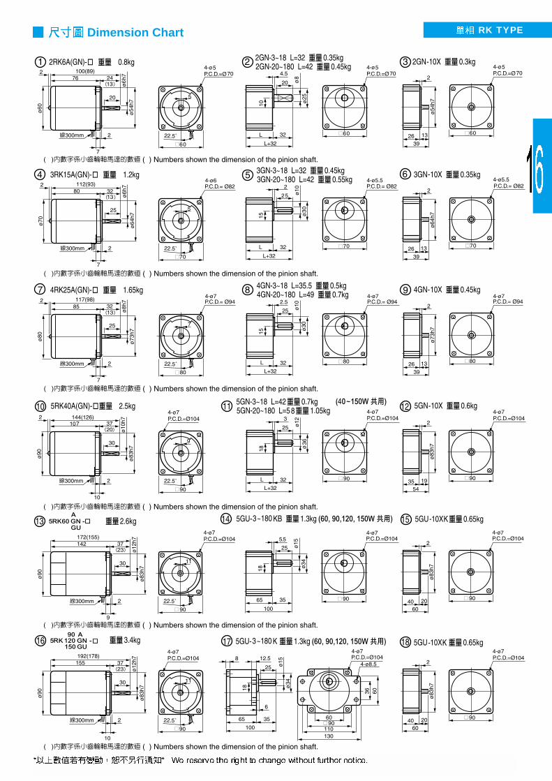
IK TYPEDimension Chart

Motor Model No. Rating Gear Model No.
Cylindrical
Output Shaft
Pinion Cut
Output Shaft
Output
(W)
Frequency
(Hz)
Voltage
(V)Current
(A)
Start Torque(gcm)
Torque(gcm)
Revolving(rpm)
BallBearing
Oil Bearing and Ball Bearing Combined
Middle Gear
Specifications of continuous operating motor
Gear Head-Torque Table (Kg•cm)
GEAR REDUCER
GEAR MOTOR
Key Dimensions(3GN 4GN 5GN) (5GU) Line Knotting Chart
rpm 500 300 200 120 100 60 50 30 20 15 10 6 5 3 2 1.5 1
50Hz 3
5 7.5 12.5 15 25 30 50 75 100 150 250 300 500 750 1000 1500
60Hz Reduction Ratio 6 9 15 18 30 36 60 90 120 180 300 360 600 900 1200 1800
25W 4 6.7 10 16 20 32 39 65 80 80 80 80 80 80 80 80 80
40W 6.7 11 16 28 33 54 65 100 100 100 100 100 100 100 100 100 100
60W 10 16 24 40 48 77 93 155 200 200 200 200 200 200 200 200 200
90W 14 23 35 58 69 110 133 200 200 200 200 200 200 200 200 200 200
120W 19 30 47 77 92 147 177 200 200 200 200 200 200 200 200 200 200
150W 22 45 68 113 136 200 200 200 200 200 200 200 200 200 200 200 200
Induction Motor (3-Phase)
4IK25A - S2 4IK25GN - S2 25 50 200
0.254600 1900 1300
60 220 3600 1800 1550
4IK25A - S3
4IK25GN - S3
2550 380
0.164600 1900 1300
4GN- K 4GN-
S4 S4 60 440 3600 1600 1500
5IK40A - S2 5IK40GN - S2 40 50 200
0.410000 3000 1300
60 220 8000 2600 1550
5IK40A - S3
5IK40GN - S3
4050 380
0.210000 3000 1300
5GN- K 5GN-
S4 S4 60 440 8000 2600 1550
5IK60A - S2 6050 200
0.613000 4500 1300
60 220 9000 3800 1550
5IK60A - S3
6050 380
0.313000 4500 1300
S4 60 440 9000 3800 1550
5IK90A - S2 9050 200
0.818000 6800 1300
60 220 13000 5700 1550
5IK90A - S3
9050 380
0.4 18000 6800 1300
S4 60 440 13000 5700 1550
5IK120A - S2 12050 200
1.341000 8650 1350
60 220 32000 7100 1650
5IK120A - S3
12050 380
0.7 41000 8650 1350
S4 60 440 32000 7100 1650
5IK150A - S2 15050 200
0.941000 11300 1350
60 220 32000 9450 1650
5IK150A - S3
15050 380
0.5 41000 11300 1350
S4 60 440 32000 9450 1650
5IK60GN
- S2GU
5IK60GN
- S3
GU S4
5IK90GN
- S2GU
5IK90GN
- S3
GU S4
5IK120GN
- S2GU
5IK120GN
- S3
GU S4
5IK150GN
- S2GU
5IK150GN
- S3
GU S4
5GN- K
5GU- K
5GU- KB
5GN-10X
5GN-10XK
5GU-10XK
5GN- K
5GU- K
5GU- KB
5GN-10XK
5GU-10XK
5GN-
5GN- K
5GU- K
5GU- KB
5GN-10XK
5GU-10XK
4GN-10X
4GN-10XK
5GN-10X
5GN-10XK
5GN- K
5GU- K
5GU- KB
5GN-10XK
5GU-10XK
(Kg•cm) x 9.8 100 = N•m

IK TYPEDimension Chart

Motor Model No. Rating Start Condenser
Gear Model No.
Cylindrical
Output Shaft
Pinion Cut
Output Shaft
Output
(W)
Frequency
(Hz)
Voltage
(V)Current
(A)
Start Torque(gcm)
Torque (gcm)
Revolving(rpm)
Capacity( F)
Resistance Voltage (WV)
BallBearing
Oil Bearing and Ball Bearing Combined
Middle Gear
Gear Head-Torque Table (Kg•cm)rpm 500 300 200 120 100 60 50 30 20 15 10 6 5 3 2 1.5 1
50Hz 3
5 7.5 12.5 15 25 30 50 75 100 150 250 300 500 750 1000 1500
60Hz Reduction Ratio 6 9 15 18 30 36 60 90 120 180 300 360 600 900 1200 1800
6W 1.0 1.6 2.5 4.1 5 8.1 9.7 16 23 25 25 25 25 25 25 25 25
15W 2.4 4.0 6.0 10 12 19 23 39 50 50 50 50 50 50 50 50 50
25W 4 6.7 10 16 20 32 39 65 80 80 80 80 80 80 80 80 80
40W 6.7 11 16 28 33 54 65 100 100 100 100 100 100 100 100 100 100
60W 10 16 24 40 48 77 93 155 200 200 200 200 200 200 200 200 200
90W 14 23 35 58 69 110 133 200 200 200 200 200 200 200 200 200 200
120W 19 30 47 77 92 147 177 200 200 200 200 200 200 200 200 200 200
150W 22 45 68 113 136 200 200 200 200 200 200 200 200 200 200 200 200
2RK6A - A 2RK6GN - A 6 50 100 0.3 500 500 1200 3 250 60 110 450 400 1550
2RK6A - C 2RK6GN - C 6 50 200 0.15 500 500 1200 1 4002GN- K 2GN-
60 220 450 400 1500
3RK15A - A 3RK15GN - A 15 50 100 0.45 900 1250 1200 6 25060 110 800 1000 1500
3RK15A - C 3RK15GN - C 15 50 200 0.22 900 1200 1200 1.5 4003GN- K 3GN-
60 220 800 1000 1500
4RK25A - A 4RK25GN - A 25 50 100 0.70 1600 2000 1250 8 25060 110 1400 1700 1500
4RK25A - C 4RK25GN - C 25 50 200 0.35 1600 2000 1250 2 4004GN- K 4GN-
60 220 1400 1600 1550
5RK40A - A 5RK40GN - A 40 50 100 1.0 3000 3000 1300 12 25060 110 2600 2600 1550
5RK40A - C 5RK40GN - C 40 50 200 0.5 3000 3000 1300 3 4005GN- K 5GN-
60 220 2600 2600 1550
5RK60A - A 60 50 100 1.9 4700 4700 1250 16 25060 110 3800 3800 1550
5RK60A - C 60 50 200 0.75 4700 4700 1250 4 400 60 220 3800 3800 1550
5RK90A - A 90 50 100 2.1 6300 7300 1200 25 25060 110 5900 5900 1550
5RK90A - C 90 50 200 1.1 6300 7300 1200 6 40060 220 5900 5900 1500
5RK120A - A 120 50 100 2.3 6500 8990 1200 28 25060 110 5800 7300 1550
5RK120A - C 120 50 200 1.1 6500 8990 1200 8 40060 220 5800 7300 1550
5RK150A - A 150 50 100 2.7 7800 11240 1300 28 250 60 110 1600
5RK150A- C 150 50 200 1.3 7800 11240 1300 8 40060 220 1600
5GN- K5GU- K5GU- KB
5GN-10X5GN-10XK5GU-10XK
5GN- K5GU- K5GU- KB
5GN-10XK5GU-10XK
5GN- K5GU- K5GU- KB
5GN-10XK5GU-10XK
2GN-10X2GN-10XK
3GN-10X3GN-10XK
4GN-10X4GN-10XK
5GN-10X5GN-10XK
5GN- K5GU- K5GU- KB
5GN-10XK5GU-10XK
5GN-
(Kg•cm) x 9.8 100 = N•m
GEAR REDUCER
GEAR MOTOR
Reversible Motor (Single Phase)(for Bi-Directional Operation or Instantaneous Reversal of Direction)
Specifications of RK Type 30-minutes rated motor
Key Dimensions Line Knotting Chart
(3GN
4GN5GN)
(5GU)
5RK60GN - AGU
5RK60GN - CGU
5RK90GN - AGU
5RK90GN - CGU
5RK120GN - AGU
5RK120GN - CGU
5RK150GN - AGU
5RK150GN - CGU
RK TYPEDimension Chart

Motor Model No. Rating Start Condenser
Gear Model No.
Cylindrical
Output Shaft
Pinion Cut
Output Shaft
Output
(W)
Frequency
(Hz)
Voltage
(V)Current
(A)
Start Torque(gcm)
Torque (gcm)
Revolving(rpm)
Capacity( F)
Resistance Voltage (WV)
BallBearing
Oil Bearing and Ball Bearing Combined
Middle Gear
Gear Head-Torque Table (Kg•cm)rpm 500 300 200 120 100 60 50 30 20 15 10 6 5 3 2 1.5 1
50Hz 3 5 7.5 12.5 15 25 30 50 75 100 150 250 300 500 750 1000 1500
60Hz Reduction Ratio 6 9 15 18 30 36 60 90 120 180 300 360 600 900 1200 1800
6W 1.0 1.6 2.5 4.1 5 8.1 9.7 16 23 25 25 25 25 25 25 25 25
15W 2.4 4.0 6.0 10 12 19 23 39 50 50 50 50 50 50 50 50 50
25W 4 6.7 10 16 20 32 39 65 80 80 80 80 80 80 80 80 80
40W 6.7 11 16 28 33 54 65 100 100 100 100 100 100 100 100 100 100
60W 10 16 24 40 48 77 93 155 200 200 200 200 200 200 200 200 200
90W 14 23 35 58 69 110 133 200 200 200 200 200 200 200 200 200 200
120W 19 30 47 77 92 147 177 200 200 200 200 200 200 200 200 200 200
150W 22 45 68 113 136 200 200 200 200 200 200 200 200 200 200 200 200
2 IK6A - AB 2 IK6GN - AB 6 50 100 0.3 500 420 1200 2.5 25060 110 400 1450
2 IK6A - CB 2 IK6GN - CB 6 50 200 0.15 500 420 1200 0.8 4002GN- K 2GN-
60 220 400 1450
3 IK15A - AB 3 IK15GN - AB 15 50 100 0.45 900 800 1250 4 25060 110 850 1550
3 IK15A - CB 3 IK15GN - CB 15 50 200 0.22 900 800 1250 1 4003GN- K 3GN-
60 220 850 1550
4 IK25A - AB 4 IK25GN - AB 25 50 100 0.7 1600 1300 1250 6 25060 110 1500 1550
4 IK25A - CB 4 IK25GN - CB 25 50 200 0.35 1600 1300 1250 1.5 4004GN- K 4GN-
60 220 1500 1550
5 IK40A - AB 5 IK40GN - AB 40 50 100 1.0 3000 2300 1300 10 25060 110 2600 1550
5 IK40A - CB 5 IK40GN - CB 40 50 200 0.5 2700 2300 1300 2.5 4005GN- K 5GN-
60 220 2600 1550
5 IK60A - AB 60 50 100 1.4 3200 3300 1300 14 25060 110 3000 1550
5 IK60A - CB 60 50 200 0.7 3200 3300 1300 3.5 400 60 220 3000 1550
5 IK90A - AB 90 50 100 2.0 4500 5200 1300 20 25060 110 1550
5 IK90A - CB 90 50 200 1.0 4500 5200 1300 5 40060 220 1550
5 IK120A - AB 120 50 100 2.1 6500 8990 1300 25 25060 110 5800 1600
5 IK120A - CB 120 50 200 1.0 6500 8990 1300 6 40060 220 5800 1600
5 IK150A - AB 150 50 100 2.7 7800 11240 1300 28 25060 110 1600
5 IK150A - CB 150 50 200 1.3 7800 11240 1300 8 40060 220 1600
5GN- K5GU- K5GU- KB
5GN-10X5GN-10XK5GU-10XK
5GN- K5GU- K5GU- KB
5GN-10XK5GU-10XK
2GN-10X2GN-10XK
3GN-10X3GN-10XK
4GN-10X4GN-10XK
5GN-10X5GN-10XK
5GN- K5GU- K5GU- KB
5GN-10XK5GU-10XK
5GN- K5GU- K5GU- KB
5GN-10XK5GU-10XK
5GN-
(Kg•cm) x 9.8 100 = N•m
Electromagnetic Brake Motor (Single Phase)
Specifications of IKB Type Motor
GEAR REDUCER
GEAR MOTOR
Key Dimensions(3GN 4GN 5GN) (5GU) Line Knotting Chart
5IK60GN - ABGU
5IK60GN - CBGU
5IK90GN - ABGU
5IK90GN - CBGU
5IK120GN - ABGU
5IK120GN - CBGU
5IK150GN - ABGU
5IK150GN - CBGU

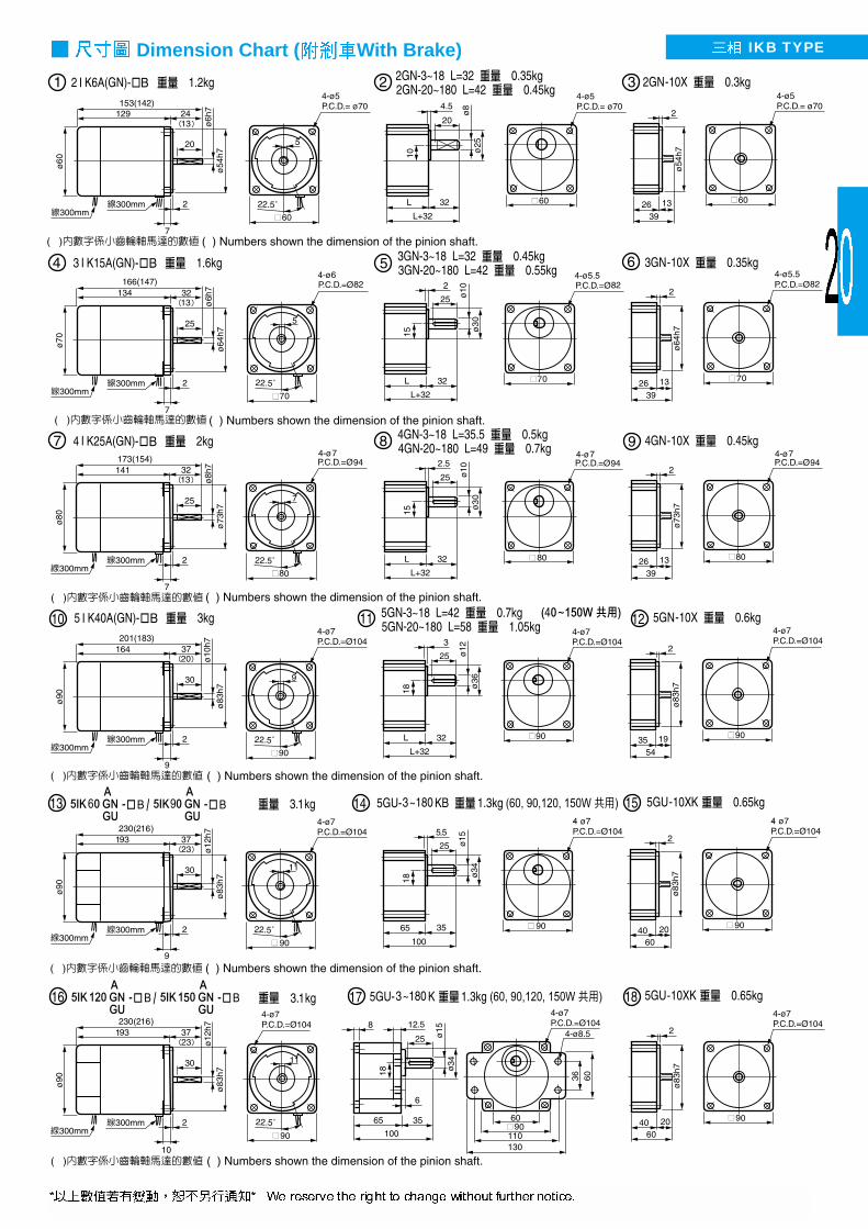
IKB TYPEDimension Chart With Brake

Motor Model No. Rating Gear Model No.
Cylindrical
Output Shaft
Pinion Cut
Output Shaft
Output
(W)
Frequency
(Hz)
Voltage
(V)Current
(A)
Start Torque(gcm)
Torque(gcm)
Revolving(rpm)
BallBearing
Oil Bearing and Ball Bearing Combined
Middle Gear
Gear Head-Torque Table (Kg•cm)rpm 500 300 200 120 100 60 50 30 20 15 10 6 5 3 2 1.5 1
50Hz 3 5 7.5 12.5 15 25 30 50 75 100 150 250 300 500 750 1000 1500
60Hz Reduction Ratio 6 9 15 18 30 36 60 90 120 180 300 360 600 900 1200 1800
25W 4 6.7 10 16 20 32 39 65 80 80 80 80 80 80 80 80 80
40W 6.7 11 16 28 33 54 65 100 100 100 100 100 100 100 100 100 100
60W 10 16 24 40 48 77 93 155 200 200 200 200 200 200 200 200 200
90W 14 23 35 58 69 110 133 200 200 200 200 200 200 200 200 200 200
120W 19 30 47 77 92 147 177 200 200 200 200 200 200 200 200 200 200
150W 22 45 68 113 136 200 200 200 200 200 200 200 200 200 200 200 200
4IK25A - S2B 4IK25GN - S2B 25 50 200
0.25 4600 1900 1300
60 220 3600 1600 1550 4GN- K 4GN-
4GN-10X
4IK25A - S3B
4IK25GN - S3B
25 50 380
0.164600 1900 1300 4GN-10XK
S4B S4B 60 440 3600 1600 1550
5IK40A - S2B 5IK40GN - S2B 4050 200
0.410000 3000 1300
60 220 8000 2600 1550 5GN- K 5GN-
5GN-10X
5IK40A - S3B
5IK40GN - S3B
4050 380
0.210000 3000 1300 5GN-10XK
S4B S4B 60 440 8000 2600 1550
5IK60A - S2B 60 50 200
0.613000 4500 1300
60 220 9000 3800 1550
5IK60A - S3B
6050 380
0.313000 4500 1300
S4B 60 440 9000 3800 1550
5IK90A - S2B 9050 200
0.818000 6800 1300
60 220 13000 5700 1550
5IK90A - S3B
9050 380
0.418000 6800 1300
S4B 60 440 13000 5700 1550
5IK120A - S2B 120 50 200 1.3
41000 8650 1350 60 220 32000 7100 1650
5IK120A - S3B
12050 380
0.7 41000 8650 1350
S4B 60 440 32000 7100 1650
5IK150A - S2B 15050 200 0.9 41000 11300 1350 60 220 32000 9450 1650
5IK150A - S3B
15050 380
0.5 41000 11300 1350
S4B 60 440 32000 9450 1650
(Kg•cm) x 9.8 100 = N•m
5GN- K
5GU- K
5GU- KB
5GN-10X
5GN-10XK
5GU-10XK
5GN- K
5GU- K
5GU- KB
5GN-10XK
5GU-10XK
5GN-
5GN- K
5GU- K
5GU- KB
5GN-10XK
5GU-10XK
5GN- K
5GU- K
5GU- KB
5GN-10XK
5GU-10XK
GEAR REDUCER
GEAR MOTOR
Line Knotting Chart
Specifications of IKB Type Motor(3-Phase)
(3GN 4GN 5GN) (5GU)
Key Dimensions
Electromagnetic Brake Motor (3-Phase)
5IK60GN
- S2BGU
5IK60GN
- S3BGU S4B
5IK90GN
- S2BGU
5IK90GN
- S3BGU S4B
5IK120GN
- S2BGU
5IK120GN
- S3BGU S4B
5IK150GN
- S2BGU
5IK150GN
- S3BGU S4B
IKB TYPEDimension Chart ( With Brake)
M206-001 6 100 50
4 90~1400
1:15 460 250 330 0.3 23 2.5 250M206-401110 60 90~1700
M206-002 6 200 50
4 90~1400
1:15 460 250 330 0.15 23 0.8 400M206-402220 60 90~1700
M315-001 15 100 50
490~1400
1:15880
300 550 0.5 40 4 250M315-401110 60 90~1700 660
M315-002 15 200 50
4 90~1400
1:15880
300 550 0.25 40 1 400M315-402220 60 90~1700 660
M425-001 25100 50
490~1400
1:15 1760
450 1200 0.7 60 6 250M425-401110 60 90~1700 1400
M425-002 25200 50
490~1400
1:151760
450 1200 0.35 60 1.5 400M425-402220 60 90~1700 1400
M540-001 40100 50
4 90~1400
1:152800
550 1900 1.0 90 10 250M540-401110 60 90~1700 1800
M540-002 40200 50
490~1400
1:152800
550 1900 0.5 90 2.5 400 M540-402220 60 90~1700 1800
Motor Model No.
(Ratio)
Variable Speed Range
1200rpm 90rpm Cylindrical
Output Shaft
Pinion Cut
Output Shaft
Output(W)
Frequency
(Hz)
Voltage
(V)Pole
(P)
Torque (gcm)
Starting Torque (gcm)
Current
(A)Revolving
( rpm)
Set Revolving No. Capacity
( F)
Resistance Voltage (WV)
ConsumedPower
(W)
Condenser
Stepless Variable Speed Control Motor (Single Phase)Specifications of US Type Motor(Single-Phase)
Gear Head-Torque Table (Kg•cm)
GEAR REDUCER
GEAR MOTOR
Dimensions of Control Unit
90~1700 0.3~0.5 0.45~1.2 0.6~1.8 0.8~2.5 1.0~3 1.6~5
15~283 1.5~2.4 2GN-6 2.4~7 3GN-6 2.9~8.8 4GN-6 3.9~12 5GN-6 4.6~15 5GU-6K 8~24 5GU-6K
5~94.4 4.4~7.3 2GN-18 6.5~18 3GN-18 8.8~26 4GN-18 12~37 5GN-18 16~50 5GU-18K 45~75 5GU-18K
1.5~28.3 12~20 2GN-60 16~ 3GN-60 24~71 4GN-60 32~100 5GN-60 45~120 5GU-60K 64~150 5GU-60K
1~18.8 18~25 2GN-90 25~70 3GN-90 36~80 4GN-90 48~100 5GN-90 60~125 5GU-90K 95~180 5GU-90K
0.5~9.4 25 2GN-180 70 3GN-180 80 4GN-180 90~100 5GN-180 100~125 5GU-180K 150~180 5GU-180K
M206-001, -201-401 M315-001, -201-401 M425-001, -201-401 M540-001, -201-401 M560-001, -401-501 M590-001,-401-501
/ M206-002, -202-402 M315-002, -202-402 M425-002, -202-402 M540-002, -202-402 M560-002, -402-502 M590-002,-402-502
Variable Speed
Range (rpm) Torque Gear Ratio Torque Gear Ratio Torque Gear Ratio Torque Gear Ratio Torque Gear Ratio Torque Gear Ratio
M560-001M560-401 100 50 90~1400 5000M560-501
60110 60
490~1700
1:15 3500
700 3000 1.8 150 14 250
M560-002M560-402 200 50 90~1400 5000M560-502
60220 60
490~1700
1:153500
700 3000 0.9 150 3.5 400
M590-001 M590-401
90 100 50
4 90~1400
1:156600
1100 4500 2.0 200 20 250M590-501 110 60 90~1700 5300
M590-002M590-402
90200 50
490~1400
1:15 6600
1100 4500 1.0 200 5 400M590-502 220 60 90~1700 5300
M5120-001 M5120-401
120 100 50
4 90~1400
1:158500
1400 6500 2.1 230 25 250M5120-501 110 60 90~1700 7000
M5120-002M5120-402
120200 50
490~1400
1:15 8500
1400 6500 1.0 230 6 400M5120-502 220 60 90~1700 7000
(Kg•cm) x 9.8 100 = N•m

US TYPEDimension Chart

M206-001B M206-401B 6 100 50 4 90~1400 1:15 460 250 330 0.3 23 2.5 250110 60 90~1700
M206-002B M206-402B 6 200 50 4 90~1400 1:15 460 250 330 0.15 23 0.8 400220 60 90~1700
M315-001B M315-401B 15 100 50 4 90~1400 1:15 880 300 550 0.5 40 4 250110 60 90~1700 660
M315-002B M315-402B 15 200 50 4 90~1400 1:15 880 300 550 0.25 40 1 400220 60 90~1700 660
M425-001B M425-401B 25 100 50 4 90~1400 1:15 1760 450 1200 0.7 60 6 250110 60 90~1700 1400
M425-002B M425-402B 25 200 50 4 90~1400 1:15 1760 450 1200 0.35 60 1.5 400220 60 90~1700 1400
M540-001B M540-401B 40 100 50 4 90~1400 1:15 2800 550 1900 1.0 90 10 250110 60 90~1700 1800
M540-002B M540-402B 40 200 50 4 90~1400 1:15 2800 550 1900 0.5 90 2.5 400220 60 90~1700 1800
M560-001B M560-401B 60 100 50 4 90~1400 1:15 5000 700 3000 1.8 150 14 250M560-501B 110 60 90~1700 3500
M560-002B M560-402B 60 200 50 4 90~1400 1:15 5000 700 3000 0.9 150 3.5 400M560-502B 220 60 90~1700 3500
M590-001B M590-401B 90 100 50 4 90~1400 1:15 6600 1100 4500 2.0 200 20 250M590-501B 110 60 90~1700 5300
M590-002B M590-402B 90 200 50 4 90~1400 1:15 6600 1100 4500 1.0 200 5 400M590-502B 220 60 90~1700 5300
M5120-001 M5120-401B 120 100 50 4 90~1400 1:15 8500 1400 6500 2.1 230 25 250M5120-501B 110 60 90~1700 7000
M5120-002 M5120-402B 120 200 50 4 90~1400 1:15 8500 1400 6500 1.0 230 6 400M5120-502B 220 60 90~1700 7000
Motor Model No.
(Ratio)
Variable Speed Range
1200rpm 90rpm Cylindrical
Output Shaft
Pinion Cut
Output Shaft
Output(W)
Frequency
(Hz)
Voltage
(V)Pole
(P)
Torque (gcm)
Starting Torque (gcm)
Current
(A)Revolving
(rpm)
Set Revolving No. Capacity
( F)
Resistance Voltage (WV)
ConsumedPower
(W)
Condenser
Specifications of USB Type Motor (Single-Phase)
Stepless Variable Speed Control Motor with Electromagnetic Brake (Single-Phase)
GEAR REDUCER
GEAR MOTOR
SS31/SS32 (B)SS speed control with electromagnetic brake
( Bi Derectional Operation)
SS31/SS32 (R)SS speed control with electronic brake( Bi Directional Operation)
SS31/SS32 (R)SS speed control with electronic brake
SS31/SS32SS speed control ( Bi Directional Operation)
US ( )US speed control Unit ( Line Knotting Chart)
LineKnottingChart

US BRAKE TYPEDimension Chart

Weight Max. Thrust Speed Permissible O.H.L. Stroke Weight Stroke WeightModel No. (kg) Applicable Motor (kg) (mm/sec) (kg) (mm) (kg) (mm) (kg)10
L 2IK6GN- 20 100 0.19 400 0.532 - - 0.35 2IK6GN- B 20 30 3 200 0.30 500 0.64F M206- 40 300 0.41 600 0.75
5010 100 0.37 500 1.34
L 4IK25GN- 20 200 0.65 600 1.59 4 - - 0.65 4IK25GN- B 70 30 5 F M425- 40 300 0.88 700 1.83
50 400 1.12 800 2.0410 100 0.73 500 2.15
L 5IK40GN- 20 200 1.07 600 2.525 - - 0.87 5IK40GN- B 100 30 8
300 1.43 700 2.87F M540- 40 50 400 1.79 800 3.24
5IK60GU-
L5IK60GU- B 10 100 0.73 500 2.15
6 - - 2 M560- 140 20 200 1.07 600 2.52
F 5IK90GU- 30 8300 1.43 700 2.87
5IK90GU- B 40
M590- 50 400 1.79 800 3.24
Specifications of GNT (GUT) Type Gear Head with Motor
Application
Linear Type Gear Head with Motor
GEAR REDUCER
GEAR MOTOR
4 L 45 – 3 Ram Stroke
( )1: 100mm2: 200mm3: 300mm4: 400mm5: 500mm6: 600mm7: 700mm8: 800mm
Stroke Speed 45mm/sec.
L: Horizontal ThrustF: Vertical Thrust
Ram Section 2: 60mm(2GN) 4: 80mm(4GN) 5: 90mm(5GN)6: 90mm(5GU)

GNT GUT TYPEDimension Chart

Motor Model No. Output Force Voltage Current Revolution Torque Arrange Model
Cylindrical Output Shaft Pinion Cut Output Shaft (W) (V) (A) (rpm) (Kg•cm) of Gear Box
Specifications of DM Type Motor
Dimensions Chart
Line Knotting Chart
Red BlackNormal/Reversible change by the red wire & black
( ) ( ) Numbers shown the dimension of the gear motor
DM08ADM08GN
DM09ADM09GN/GU
DM12ADM12GU
DM Type Permanent Magnet DC Motor
GEAR REDUCER
GEAR MOTOR
DM 08 GN – 90 –
1800, 3000 RPM
Voltage 12V, 24V, 90V
Pinion Shaft: GN/GU Pinion cut
HP: 08(30W), 09(60W), 12(120W)
Permanent Magnet DC Motor (Brushed)
DM08-A DM08-GN 30 12/24 5.6/2.8 3000 1.2 4GN- 4GN- K
DM09-A DM09-GU/GN 60 12/24 9/4.5 3000 2.8 5GU- K 5GN- K
DM12-A DM12-GU 120 12/24 14/7 3000 4.3 5GU- K PL PF
DM08-A DM08-GN 30 12/24 3.8/1.8 1800 1.8 4GN- 4GN- K
DM09-A DM09-GU/GN 60 12/24 7.5/3.8 1800 3.5 5GU- K 5GN- K
DM12-A DM12-GU 120 12/24 11/5.8 1800 6.5 5GU- K PL PF
DM08-A DM08-GN 30 90 0.4 1800 1.8 4GN- 4GN- K
DM09-A DM09-GU/GN 60 90 0.8 1800 3.5 5GU- K 5GN- K
DM12-A DM12-GU 120 90 1.4 1800 6.5 5GU- K PL PF5GU- KB
5GU- KB
5GU- KB
5GU- KB
5GU- KB
5GU- KB
A
1.1 Kg 4.9 Kg
2.4 Kg

Dimensions
Dimension Chart
Output Shaft
Worm Gear Reducer with Motor
GEAR REDUCER
GEAR MOTOR
GA U 40 – 60 A BL– Output Shaft in the LeftR– Output Shaft in the RightB– With Electromagnetic BrakeT– With Terminal BoxA– Single Phase 100V~110VC– Single Phase 200V~220VS2: 220V, S3: 380V, S4: 440V
Gear Ratio 5, 10, 15, 20, 30, 40, 50, 60HP 40W, 60W, 90W, 100W, 200W
U : Variable Speed Control Motor I : Induction MotorR : 30 Reversible MotorD : DC Motor
Worm Gear Type
R-
Output Shaft in the Right L-
Output Shaft in the Left
L-
Output Shaft in the Left
L R D
( )
( ) Numbers shown the dimension of the brake
Z Output Shaft
Model No. Gear Ratio A D E F G H L M X Y
Q S T W
GAI-40- - 1/5-1/60 198 50 60 75 87 9 10 90 118 43.5 30 14 16.5 5
GAI-60- - 1/5-1/60 230 50 60 75 87 9 10 90 118 43.5 30 14 16.5 5
GAI-90- - 1/51/60 270 65 90 92.8 112 10 10 90 146 56.5 40 16 18.5 5
GAI-100- - 1/5-1/60 255 65 90 92.8 112 10 10 126 161 56.5 40 16 18.5 5
GAI-200- - 1/5-1/60 285 65 90 92.8 112 10 10 126 161 56.5 40 16 18.5 5
(248)
(288)
(300)
(330)
(330)
(Kg)
1.8
3.5
78 77 41 40
78 77 41 40
96 94 53 51
96 94 53 51
96 94 53 51
L R PL R

Examples
Torque Table (Kg•cm)
Right-Angel Gear Reducer
GEAR REDUCER
GEAR MOTOR
5 GN - 150 RH RA:
RH:
15, 20, 25, 30, 40, 45, 50, 60, 75, 90, 100, 120, 150,
160, 180, 200, 250, 300, 350, 400, 500, 600, 700
GN
4: 80mm5: 90mm
15 20 25 30 40 45 50 60 75 90 100 120 150 180 200 250 300 350 400
51.75% 53.50% 61.38%
25W 14 19 23 28 37 42 47 58 72 87 96 120 120 120 120 120 120 120 120
40W 20 27 34 40 54 61 67 83 104 125 140 140 140 140 140 140 140 140 140
60W 29 39 49 59 79 88 98 122 152 183 203 244 260 260 260 260 260 260 260
90W 44 59 74 88 118 133 147 183 229 260 260 260 260 260 260 260 260 260 260
120W 55 73 92 110 147 165 184 228 260 260 260 260 260 260 260 260 260 260 260
150W 73 98 122 147 196 220 245 260 260 260 260 260 260 260 260 260 260 260 260
500 600 700
120 120 120
140 140 140
260 260 260
260 260 260
260 260 260
260 260 260
(Kg • cm) x 9.8/100=N•m
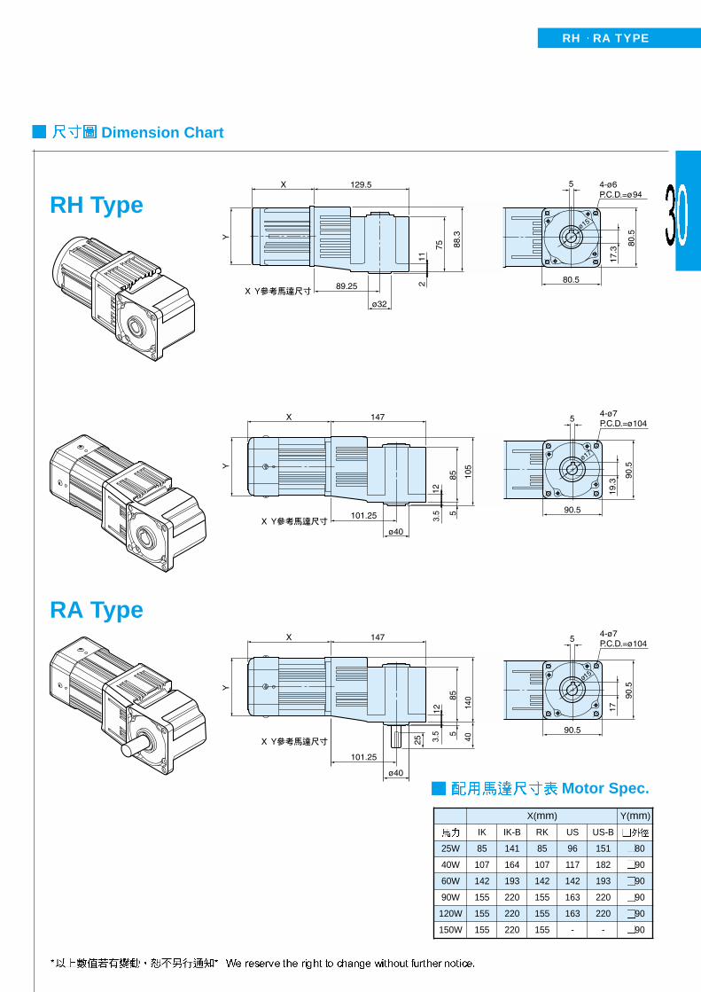
Dimension Chart
Motor Spec.
X(mm) Y(mm)
IK IK-B RK US US-B
25W 85 141 85 96 151 80
40W 107 164 107 117 182 90
60W 142 193 142 142 193 90
90W 155 220 155 163 220 90
120W 155 220 155 163 220 90
150W 155 220 155 - - 90
RH Type
RA Type
RH RA TYPE
PL–
PF–
GL–
GF–
PLD–
PFD–
PLK–
PFK–
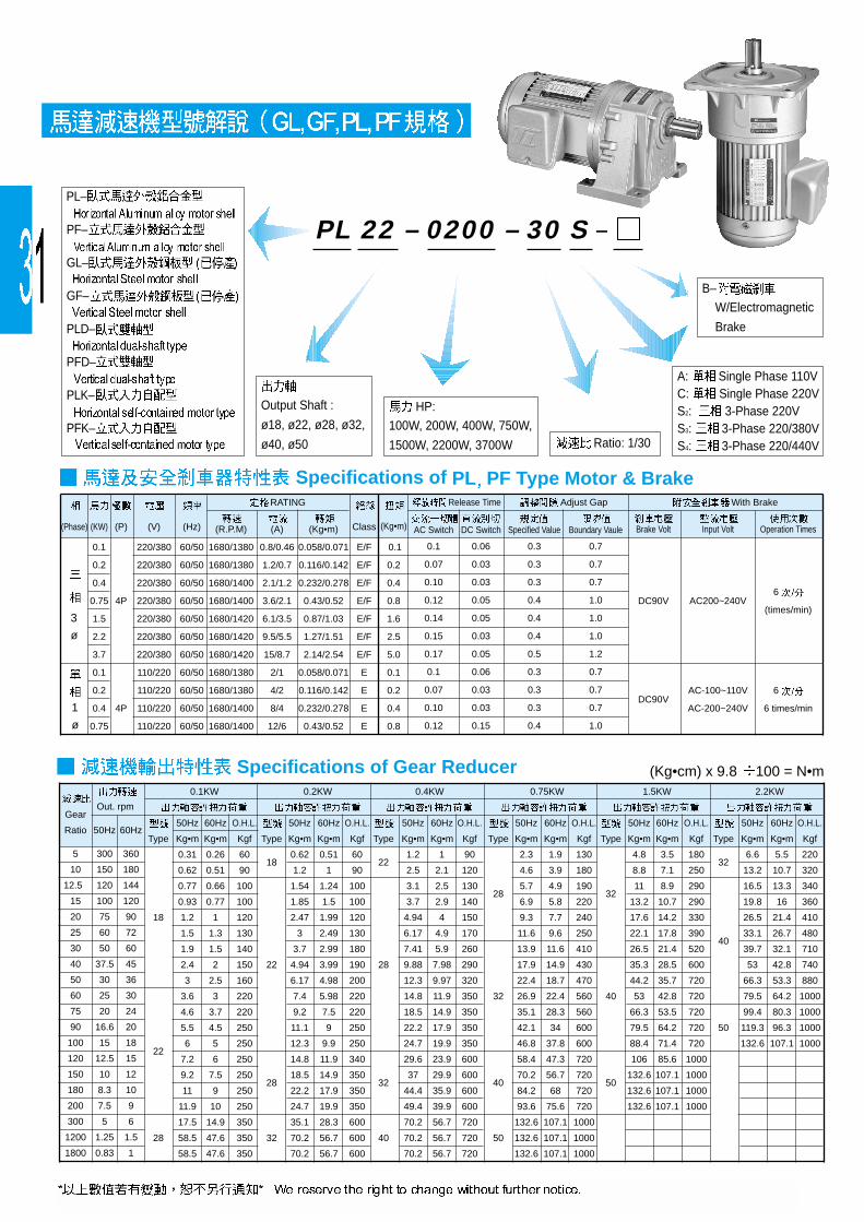
RATING With Brake
(Phase) (KW) (P) (V) (Hz) Class(R.P.M) (A) (Kg•m) (Kg•m) Brake Volt Input Volt Operation Times
0.1 220/380 60/50 1680/1380 0.8/0.46 0.058/0.071 E/F 0.1
0.2 220/380 60/50 1680/1380 1.2/0.7 0.116/0.142 E/F 0.2
0.4 220/380 60/50 1680/1400 2.1/1.2 0.232/0.278 E/F 0.4
0.75 4P 220/380 60/50 1680/1400 3.6/2.1 0.43/0.52 E/F 0.8 DC90V AC200~240V6
1.5 220/380 60/50 1680/1420 6.1/3.5 0.87/1.03 E/F 1.6 (times/min)
2.2 220/380 60/50 1680/1420 9.5/5.5 1.27/1.51 E/F 2.5
3.7 220/380 60/50 1680/1420 15/8.7 2.14/2.54 E/F 5.0
0.1 110/220 60/50 1680/1380 2/1 0.058/0.071 E 0.1
0.2 110/220 60/50 1680/1380 4/2 0.116/0.142 E 0.2 AC-100~110V 6
0.4 4P 110/220 60/50 1680/1400 8/4 0.232/0.278 E 0.4 DC90V
AC-200~240V 6 times/min
0.75 110/220 60/50 1680/1400 12/6 0.43/0.52 E 0.8
Release Time Adjust Gap
AC Switch DC Switch Specified Value Boundary Vaule
0.1 0.06 0.3 0.7
0.07 0.03 0.3 0.7
0.10 0.03 0.3 0.7
0.12 0.05 0.4 1.0
0.14 0.05 0.4 1.0
0.15 0.03 0.4 1.0
0.17 0.05 0.5 1.2
0.1 0.06 0.3 0.7
0.07 0.03 0.3 0.7
0.10 0.03 0.3 0.7
0.12 0.15 0.4 1.0
Gear Out. rpm
Ratio 50Hz 60Hz
5 300 360
10 150 180
12.5 120 144
15 100 120
20 75 90
25 60 72
30 50 60
40 37.5 45
50 30 36
60 25 30
75 20 24
90 16.6 20
100 15 18
120 12.5 15
150 10 12
180 8.3 10
200 7.5 9
300 5 6
1200 1.25 1.5
1800 0.83 1
0.1KW
50Hz 60Hz O.H.L.
Type Kg•m Kg•m Kgf
0.31 0.26 60
0.62 0.51 90
0.77 0.66 100
0.93 0.77 100
18 1.2 1 120
1.5 1.3 130
1.9 1.5 140
2.4 2 150
3 2.5 160
3.6 3 220
4.6 3.7 220
5.5 4.5 250
6 5 250 22
7.2 6 250
9.2 7.5 250
11 9 250
11.9 10 250
17.5 14.9 350
28 58.5 47.6 350
58.5 47.6 350
0.2KW
50Hz 60Hz O.H.L.
Type Kg•m Kg•m Kgf
0.62 0.51 60 18
1.2 1 90
1.54 1.24 100
1.85 1.5 100
2.47 1.99 120
3 2.49 130
3.7 2.99 180
22 4.94 3.99 190
6.17 4.98 200
7.4 5.98 220
9.2 7.5 220
11.1 9 250
12.3 9.9 250
14.8 11.9 340
18.5 14.9 350 28
22.2 17.9 350
24.7 19.9 350
35.1 28.3 600
32 70.2 56.7 600
70.2 56.7 600
0.4KW
50Hz 60Hz O.H.L.
Type Kg•m Kg•m Kgf
1.2 1 90 22
2.5 2.1 120
3.1 2.5 130
3.7 2.9 140
4.94 4 150
6.17 4.9 170
7.41 5.9 260
28 9.88 7.98 290
12.3 9.97 320
14.8 11.9 350
18.5 14.9 350
22.2 17.9 350
24.7 19.9 350
29.6 23.9 600
37 29.9 600 32
44.4 35.9 600
49.4 39.9 600
70.2 56.7 720
40 70.2 56.7 720
70.2 56.7 720
0.75KW
50Hz 60Hz O.H.L.
Type Kg•m Kg•m Kgf
2.3 1.9 130
4.6 3.9 180
5.7 4.9 190 28
6.9 5.8 220
9.3 7.7 240
11.6 9.6 250
13.9 11.6 410
17.9 14.9 430
22.4 18.7 470
32 26.9 22.4 560
35.1 28.3 560
42.1 34 600
46.8 37.8 600
58.4 47.3 720
70.2 56.7 720 40
84.2 68 720
93.6 75.6 720
132.6 107.1 1000
50 132.6 107.1 1000
132.6 107.1 1000
1.5KW
50Hz 60Hz O.H.L.
Type Kg•m Kg•m Kgf
4.8 3.5 180
8.8 7.1 250
11 8.9 290 32
13.2 10.7 290
17.6 14.2 330
22.1 17.8 390
26.5 21.4 520
35.3 28.5 600
44.2 35.7 720
40 53 42.8 720
66.3 53.5 720
79.5 64.2 720
88.4 71.4 720
106 85.6 1000
132.6 107.1 100050
132.6 107.1 1000
132.6 107.1 1000
2.2KW
50Hz 60Hz O.H.L.
Type Kg•m Kg•m Kgf
6.6 5.5 220 32
13.2 10.7 320
16.5 13.3 340
19.8 16 360
26.5 21.4 410
33.1 26.7 480 40
39.7 32.1 710
53 42.8 740
66.3 53.3 880
79.5 64.2 1000
99.4 80.3 1000
50 119.3 96.3 1000
132.6 107.1 1000
Specifications of PL PF Type Motor & Brake
Specifications of Gear Reducer
3
ø
1
ø
PL 22 – 0200 – 30 S –
B–
W/Electromagnetic
Brake
A: Single Phase 110VC: Single Phase 220VS2: 3-Phase 220VS3: 3-Phase 220/380VS4: 3-Phase 220/440VRatio: 1/30
HP:
100W, 200W, 400W, 750W,
1500W, 2200W, 3700W
Output Shaft :
ø18, ø22, ø28, ø32,
ø40, ø50
(Kg•cm) x 9.8 100 = N•m

Type g Lubrication
18 180
22 250
28 500
32 650 BT-860
40 900
50 1200
No. Name of Parts
1 Bracket(Brake Coil Included)
2 Brake Shoe
3 Output Fan
4 Bearing Cover
5 Spring Compression
6 Hex Screw
7 Hex Screw
8 Brake Plate
9 Motor Spindle
10 Brake Shoe Fixing Ring
11 Power Device for Brake(Rectifier)
Type Material
18 ADC 12 ( Aluminum)
22 ADC 12 ( Aluminum)
28 ADC 12 ( Aluminum)
32 ADC 12 ( Aluminum)
40 FC200 (20)- ( Cast Iron)
50 FC200 (20)- ( Cast Iron)
Shell Material
Gear Reducer Structure
Brake Structure
Line Knotting Chart
Oil Capacities
No. Name of Parts
1 Motor
2 Motor Bearing
3 Oil Seal (Out)
4 Oil Seal (In)
5 2nd Stage Bearing
6 1st Stage Gear
7 Motor Pinion Shaft
8 2nd Stage Pinion Shaft
9 Body Cover
10 Body
11 "O" Ring
12 Needle Bearing (Sleeve)
13 Thrust Washer
14 Output Gear
15 Output Shaft
16 Output Shaft Bearing
17 2nd Stage Gear
18 3rd Stage Pinion
19 3rd Stage Bearing
20 Middle Stage Gear
Line knotting chart of the brake are shown as below..
(Three Phase) (Single Phase)
Mobil
SHC
Mobiltemp 0

Dimensions
PL Type 3-Phase Horizontal Gear Reduction Motor(Foot Mounted)
GEAR REDUCER
GEAR MOTOR
Output Shaft
HP Gear Ratio A A1 D E F G H L J K M X Y Z
P Q S T W
5~50 255 282 40 110 135 65 9 10 15.98 50 125 127 85 116 30 22 18 20 5 0.1KW
60~200 287 314 65 130 155 90 11 12 17.66 60 125 145 90 116 40 30 22 25 7 |
250~1800 356 383 65 130 155 90 11 12 17.66 60 125 145 90 116 40 30 22 25 7 1/8HPx4P
250~1800 393 420 90 140 170 120 11 17 39.1 70 125 170 110 100 45 35 28 31 7
5~10 273 301 40 110 135 65 9 10 15.98 50 125 127 85 116 30 22 18 20 5
12.5~25 273 301 40 110 135 65 9 10 15.98 50 125 127 85 116 30 22 18 20 5 0.2KW
12.5~100 305 330 65 130 155 90 11 12 17.66 60 125 145 90 116 40 30 22 25 7 |
120~200 334 361 90 140 170 120 11 17 23.11 70 125 170 110 100 45 35 28 31 7 1/4HPx4P
250~1800 411 437 90 140 170 120 11 17 23.11 70 125 170 110 100 45 35 28 31 7
250~1800 443 471 130 170 210 167 13 18 30.22 75 125 204 130 116 55 45 32 36.5 10
5~10 323 350 65 130 155 90 11 12 17.66 60 125 145 90 116 40 30 22 25 7
0.4KW12.5~25 323 350 65 130 155 90 11 12 17.66 60 125 145 90 116 40 30 22 25 7
|12.5~100 352 379 90 140 170 120 11 17 23.11 70 125 170 110 100 45 35 28 31 7
1/2HPx4P 120~200 382 409 130 170 210 167 13 18 30.22 75 125 204 130 116 55 45 32 36.5 10
250~1800 464 491 130 170 210 167 13 18 30.22 75 125 204 130 116 55 45 32 36.5 10
250~1800 542 569 150 210 260 200 18 23 37.96 96 125 252 160 116 65 55 40 44
5~25 379 405 90 140 170 120 11 17 23.11 70 158 170 110 131 45 35 28 31 7
0.75KW 30~100 409 470 130 170 210 167 13 18 30.22 75 158 204 130 131 55 45 32 36.5 10
| 120~200 465 491 150 210 260 200 18 23 37.96 96 158 252 160 131 65 55 40 44
1HPx4P 250~1800 569 595 150 210 260 200 18 23 37.96 96 158 252 160 131 65 55 40 44
250~1800 580 606 160 230 285 210 18 25 39.2 104 158 293 176 – 75 65 50 53.5 14
1.5KW 5~30 442 477 130 170 210 167 13 18 30.22 75 190 204 130 138 55 45 32 36.5 10
| 40~100 498 533 150 210 260 200 18 23 37.96 96 190 252 160 138 65 55 40 44
2HPx4P 120~200 509 543 160 230 285 210 18 25 39.2 104 190 293 176 – 75 65 50 53.5 14
2.2KW 5~10 467 502 130 170 210 167 13 18 30.22 75 190 204 130 138 55 45 32 36.5 10
| 15~60 523 558 150 210 260 200 18 23 37.96 96 190 252 160 138 65 55 40 44
3HPx4P 75~120 534 569 160 230 285 210 18 25 39.2 104 190 293 176 – 75 65 50 53.5 14
3.7KW 5~20 552 586 150 210 260 200 18 23 37.96 96 230 252 160 190 65 55 40 44
5HPx4P 25~100 562 597 160 230 285 210 18 25 39.2 104 230 293 176 190 75 65 50 53.5 14
Type
18
22
22
28
18
18
22
28
28
32
22
22
28
32
32
40
28
32
40
40
50
32
40
50
32
40
50
40
50
App.Wt.Kg
6.1
7.0
8.9
11.6
7.04
7.1
8.8
12
12.4
24.6
9.3
10.6
12.1
25.2
27.6
45.2
15.1
22
45.2
47.7
60.5
25
47.7
55.0
35.2
49.1
58.0
67
72
1. A1 . 2. . 3. 1/8~1 HP 2 KG.4. 2~3 HP , 3.5 KG. 5. 40~50 O ( 50 mm).6. 40mm (w) 10mm 12mm .
1. Length of A1 is the total length of motor and the brake. 2.Colour in Light blue indicates motor of smaller torque.3. Weight of 1/8 ~ 1HP motor w / brake shall be weight of motor w / 0 brake + 2Kg. 4. Weight of a 2~3HP motor w / brake is equal to motor w/0 brake + 3.5kg. 5. " O " type rings shall be attached to the 40 ~ 50mm gear box. (add. Height: 50mm).6. Keyway (w) for type 40 is 10mm, 12mm is optional.
10(12)
10(12)10(12)
10(12)
10(12)
10(12)

A1
Remark
A2
A2
A2
A1
A1
A2
A2
A2
A2
A2
A2
A2
A2
A2
A2
A2
A2
A2
A2
A2
A2
A2
A2
A2
A2
A2
A2
A2
Dimensions
GEAR REDUCER
GEAR MOTOR
Type
18
22
22
28
18
18
22
28
28
32
22
22
28
32
32
40
28
32
40
40
50
32
40
50
32
40
50
40
50
*14L
*14L
*14L
*14L
*14L
PF Type 3-Phase Vertical Gear Reduction Motor(with Flange)
Output Shaft
HP Gear Ratio A A1 D E X F G H L J K M Y Z
P Q S T W
5~50 255 282 50 140 99 122 120 9 12 15.98 40 125 5 116 30 22 18 20 5 0.1KW
60~200 287 314 148 185 131 168 165 11 12 17.66 50 125 3.5 116 40 30 22 25 7 |
250~1800 356 383 148 185 131 168 165 11 12 17.66 50 125 3.5 116 40 30 22 25 7 1/8HPx4P
250~1800 393 420 170 220 156 205 195 ø11 13 23.11 60 125 4 116 45 35 28 31 7
5~10 273 302 50 140 99 122 120 9 12 15.98 40 125 5 116 30 22 18 20 5
12.5~25 273 302 50 140 99 122 120 9 12 15.98 40 125 5 116 30 22 18 20 5 0.2KW
12.5~100 305 330 148 185 131 168 165 11 12 17.66 50 125 3.5 116 40 30 22 25 7 |
120~200 334 361 170 220 156 205 195 ø11 13 23.11 60 125 4 116 45 35 28 31 7 1/4HPx4P
250~1800 411 437 170 220 156 205 195 ø11 13 23.11 60 125 4 116 45 35 28 31 7
250~1800 443 471 185 255 180 241 225 15 15 30.22 70 125 4 116 55 40 32 36.5 10
5~10 325 350 148 185 131 168 165 11 12 17.66 50 125 3.5 116 40 30 22 25 7
0.4KW12.5~25 325 350 148 185 131 168 165 11 12 17.66 50 125 3.5 116 40 30 22 25 7
|12.5~100 352 380 170 220 156 205 195 ø11 13 23.11 60 125 4 – 45 35 28 31 7
1/2HPx4P 120~200 385 410 185 255 180 241 225 15 15 30.22 70 125 4 116 55 45 32 36.5 10
250~1800 465 592 185 255 180 241 225 15 15 30.22 70 125 4 116 55 45 32 36.5 10
250~1800 545 570 230 310 219 297 268 15 20 37.96 76 125 5 – 65 55 40 44
5~25 380 405 170 220 156 205 195 ø11 13 23.11 60 158 4 131 45 35 28 31 7
0.75KW 30~100 410 435 185 255 180 241 225 15 15 30.22 70 158 4 131 55 45 32 36.5 10
| 120~200 465 492 230 310 219 297 268 15 20 37.96 76 158 5 – 65 55 40 44
1HPx4P 250~1800 570 595 230 310 219 297 268 15 20 37.96 76 158 5 – 65 55 40 44
250~1800 580 606 250 352 249 320 290 18 22 39.2 86 158 5 – 75 65 50 53.5 14
1.5KW 5~30 442 478 185 255 180 241 225 15 15 30.22 70 190 4 138 55 45 32 36.5 10
| 40~100 500 535 230 310 219 297 268 15 20 37.96 76 190 5 138 65 55 40 44
2HPx4P 120~200 510 543 250 352 249 320 290 18 22 39.2 86 190 5 – 75 65 50 53.5 14
2.2KW 5~10 467 502 185 255 180 241 225 15 15 30.22 70 190 4 138 55 45 32 36.5 10
| 15~60 525 560 230 310 219 297 268 15 20 37.96 76 190 5 138 65 55 40 44
3HPx4P 75~120 535 570 250 352 249 320 290 18 22 39.2 86 190 5 – 75 65 50 53.5 14
3.7KW 5~20 552 586 230 310 219 297 268 15 20 37.96 82 230 5 190 65 55 40 44
5HPx4P 25~100 565 600 250 352 249 320 290 18 22 39.2 86 230 5 190 75 65 50 53.5 14
App.Wt.Kg
6.08
7.3
9.8
11.9
7.1
7.13
8.81
11.7
12.8
25.2
9.62
11
13.4
24.4
26.8
45.6
15.1
26.9
45.6
48.1
57.3
26.5
49.3
60.2
34.2
50.8
55.6
56.5
60.0
1. A1 . 2. . 3. 1/8~1 HP 2KG. 4. 2~3 HP , 3.5 KG.5. 40mm (w) 10mm 12mm .
1. Length of A1 is the total length of motor and the brake. 2.Colour in Light blue indicates motor of smaller torque.3. Weight of 1/8 ~ 1HP motor w / brake shall be weight of motor w / 0 brake + 2Kg. 4. Weight of a 2~3HP motor w / brake is equal to motor w/0 brake + 3.5kg.5. Keyway (w) for type 40 is 10mm, 12mm is optional.
10(12)
10(12)10(12)
10(12)
10(12)
10(12)

GEAR REDUCER
GEAR MOTOR
X1
–
–
–
–
–
–
–
–
–
–
195
195
210
222
–
–
214
227
–
–
Dimensions
Type
18
22
22
28
18
18
22
28
28
32
22
22
28
32
32
40
28
32
40
40
Output Shaft
HP Gear Ratio A A1 D E F G H L J K M X Y Z
P Q S T W App.Wt.
5~50 255 281 40 110 135 65 9 10 15.98 50 125 127 85 116 30 22 18 20 5 5.60.1KW
60~200 286 313 65 130 155 90 11 12 17.66 60 125 145 90 116 40 30 22 25 7 7.0|
250~1800 356 382 65 130 155 90 11 12 17.66 60 125 145 90 116 40 30 22 25 7 8.91/8HPx4P
250~1800 393 419 90 140 170 120 11 15 23.11 70 125 170 110 116 45 35 28 31 7 11.6
5~10 290 315 40 110 135 65 9 10 15.98 50 125 127 85 116 30 22 18 20 5 6.4
12.5~25 290 315 40 110 135 65 9 10 15.98 50 125 127 85 116 30 22 18 20 5 6.40.2KW
12.5~100 322 347 65 130 155 90 11 12 17.66 60 125 145 90 116 40 30 22 25 7 7.9|
120~200 351 376 90 140 170 120 11 15 23.11 70 125 170 110 116 45 35 28 31 7 10.31/4HPx4P
250~1800 428 453 90 140 170 120 11 15 23.11 70 125 170 110 116 45 35 28 31 7 12.4
250~1800 462 487 130 170 210 167 13 18 30.22 75 125 204 130 116 55 45 32 36.5 10 24.6
5~10 380 440 65 130 155 90 11 12 17.66 60 158 145 90 131 40 30 22 25 7 12.6
0.4KW12.5~25 380 440 65 130 155 90 11 12 17.66 60 158 145 90 131 40 30 22 25 7 12.6
|12.5~100 410 470 90 140 170 120 11 15 23.11 70 158 170 110 131 45 35 28 31 7 15.0
1/2HPx4P120~200 450 510 130 170 210 167 13 18 30.22 75 158 204 130 131 55 45 32 36.5 10 27.2
250~1800 530 590 130 170 210 167 13 18 30.22 75 158 204 130 131 55 45 32 36.5 10 29.6
250~1800 600 660 150 210 260 200 18 23 37.96 96 158 252 160 131 65 55 40 44 47.2
0.75KW5~25 420 480 90 140 170 120 11 15 23.11 70 158 170 110 138 45 35 28 31 7 16.7
30~100 450 510 130 170 210 167 13 18 30.22 75 158 204 130 138 55 45 32 36.5 10 29.8|
120~200 510 570 150 210 260 200 18 23 37.96 96 158 252 160 138 65 55 40 44 47.21HPx4P
250~1800 610 670 150 210 260 200 18 23 37.96 96 158 252 160 138 65 55 40 44 49.7
Kg
PL Type Single-Phase Horizontal Gear Reduction Motor(Foot Mounted)
1. A1 . 2. . 3. 1/8~1 HP 2 KG.4. 2~3 HP , 3.5 KG. 5. 40~50 O ( 50 mm).6. 40mm (w) 10mm 12mm .
1. Length of A1 is the total length of motor and the brake. 2.Colour in Light blue indicates motor of smaller torque.3. Weight of 1/8 ~ 1HP motor w/brake shall be weight of motor w/o brake + 2Kg. 4. Weight of a 2~3HP motor w/brake is equal to motor w/0 brake + 3.5kg. 5. " O " type rings shall be attached to the 40 ~ 50mm gear box. (add. Height: 50mm)6. Keyway (w) for type 40 is 10mm, 12mm is optional.
10(12)
10(12)10(12)

Dimensions
PF Type Single-Phase Vertical Gear Reduction Motor(with Flange)
GEAR REDUCER
GEAR MOTOR
Kg
A1
Remark
A2
A2
A2
A1
A1
A2
A2
A2
A2
A2
A2
A2
A2
A2
A2
A2
A2
A2
A2
F
122
168
168
205
122
122
168
205
205
241
168
168
205
241
241
297
205
241
297
297
F1
–
–
–
–
–
–
–
–
–
–
195
195
–
–
–
–
209.5
–
–
–
Type
18
22
22
28
18
18
22
28
28
32
22
22
28
32
32
40
28
32
40
40
*14L
*14L
*14L
*14L
*14L
1. A1 . 2. . 3. 1/8~1 HP 2KG. 4. 2~3 HP , 3.5 KG.5. 40mm (w) 10mm 12mm .
1. Length of A1 is the total length of motor and the brake. 2.Colour in Light blue indicates motor of smaller torque.3. Weight of 1/8 ~ 1HP motor w/brake shall be weight of motor w/o brake + 2Kg. 4. Weight of a 2~3HP motor w/brake is equal to motor w/0 brake + 3.5kg.5. Keyway (w) for type 40 is 10mm, 12mm is optional.
10(12)
10(12)10(12)
Output Shaft
HP Gear Ratio A A1 D E X G H L J K M Y Z
P Q S T WApp.Wt.
5~50 255 281 50 140 99 120 9 12 15.98 40 125 5 116 30 22 18 20 5 5.50.1KW
60~200 286 313 148 185 131 165 11 12 17.66 50 125 3.5 116 40 30 22 25 7 7.3|
250~1800 356 385 148 185 131 165 11 12 17.66 50 125 3.5 116 40 30 22 25 7 9.21/8HPx4P
250~1800 395 420 170 220 156 195 ø11 13 23.11 60 125 4 116 45 35 28 31 7 11.9
5~10 290 315 50 140 99 120 9 12 15.98 40 125 5 116 30 22 18 20 5 6.5
12.5~25 290 315 50 140 99 120 9 12 15.98 40 125 5 116 30 22 18 20 5 6.50.2KW
12.5~100 322 347 148 185 131 165 11 12 17.66 50 125 3.5 116 40 30 22 25 7 8.3|
120~200 351 376 170 220 156 195 ø11 13 23.11 60 125 4 116 45 35 28 31 7 11.71/4HPx4P
250~1800 428 453 170 220 156 195 ø11 13 23.11 60 125 4 116 45 35 28 31 7 12.8
250~1800 462 487 185 255 180 225 15 15 30.22 70 125 4 116 55 45 32 36.5 10 25.2
5~10 380 440 148 185 131 165 11 12 17.66 50 125 3.5 131 40 30 22 25 7 11
0.4KW12.5~25 380 440 148 185 131 165 11 12 17.66 50 125 3.5 131 40 30 22 25 7 11
|12.5~100 410 470 170 220 156 195 ø11 13 23.11 60 125 4 131 45 35 28 31 7 13.4
1/2HPx4P 120~200 450 510 185 255 180 225 15 15 30.22 70 125 4 131 55 45 32 36.5 10 24.4
250~1800 530 590 185 255 180 225 15 15 30.22 70 125 4 131 55 45 32 36.5 10 26.8
250~1800 600 660 230 310 219 268 15 20 37.96 76 125 5 – 65 55 40 44 47.4
5~25 420 480 170 220 156 195 ø11 13 23.11 60 158 4 138 45 35 28 31 7 15.1
0.75KW 30~100 450 510 185 255 180 225 15 15 30.22 70 158 4 138 55 45 32 36.5 10 26.9
| 120~200 510 570 230 310 219 268 15 20 37.96 76 158 5 138 65 55 40 44 47.4
1HPx4P 250~1800 610 670 230 310 219 268 15 20 37.96 76 158 5 138 65 55 40 44 49.7

Output Shaft Dimension: ø18PLD Horizontal Type (Dual-Shaft)
Ratio: 1/10HP: 200W
PLD Dual-Shaft Type Gear Reducer
GEAR REDUCER
GEAR MOTOR
1. .
2. 40~50 O ( 50mm). 3. 40mm (w) 10mm 12mm .
1. Colour in Light blue indicates motor of smaller torque.2. " O " type rings shall be attached to the 40 ~ 50mm gear box. (add. Height: 50mm).3. Keyway (w) for type 40 is 10mm, 12mm is optional.
Dimensions
PLD 18 – 0200 – 10
Type
18
22
18
18
22
28
22
22
28
32
28
32
40
32
40
50
32
40
50
40
50
KgQ1 S1 T1 W1 App.Wt.
22 14 15.5 4 3
22 14 15.5 4 4.2
22 14 15.5 4 3
22 14 15.5 4 3
22 14 15.5 4 4.2
27 16 18 5 5.5
22 14 15.5 4 4.2
22 14 15.5 4 4.2
27 16 18 5 5.5
27 19 21 5 16
27 16 18 5 6.5
27 19 21 5 19.5
32 24 27 7 38
27 19 21 5 19.5
32 24 27 7 38
42 28 31 8 51.2
27 19 21 5 20.5
32 24 27 7 39
42 28 31 8 53
32 24 27 7 39
42 28 31 8 53
Output Shaft
HP Gear Ratio A D E F G H J K L X Y Y1
P Q S T W P1
0.1KW5~50 172 40 110 135 65 9 15.98 50 10 127 85 69 30 22 18 20 5 25
60~200 204 65 130 155 90 11 17.66 60 12 145 90 72.3 40 30 22 25 7 25
5~10 172 40 110 135 65 9 15.98 50 10 127 85 69 30 22 18 20 5 25
0.2KW 12.5~25 172 40 110 135 65 9 15.98 50 10 127 85 69 30 22 18 20 5 25
12.5~100 204 65 130 155 90 11 17.66 60 12 145 90 72.3 40 30 22 25 7 25
120~200 266 90 140 170 120 11 23.11 70 15 170 110 87 45 35 28 31 7 30
5~10 204 65 130 155 90 11 17.66 60 12 145 90 72.3 40 30 22 25 7 25
0.4KW12.5~25 204 65 130 155 90 11 17.66 60 12 145 90 72.3 40 30 22 25 7 25
12.5~100 266 90 140 170 120 11 23.11 70 15 170 110 87 45 35 28 31 7 30
120~200 296 130 170 210 167 13 30.22 75 18 204 130 99.8 55 45 32 36.5 10 30
5~25 266 90 140 170 120 11 23.11 70 15 170 110 87 45 35 28 31 7 30
0.75KW 30~100 296 130 170 210 167 13 30.22 75 18 204 130 99.8 55 45 32 36.5 10 30
120~200 357 150 210 260 200 18 37.96 96 23 252 160 122 65 55 40 44 35
5~30 296 130 170 210 167 13 30.22 75 18 204 130 99.8 55 45 32 36.5 10 30
1.5KW 40~100 357 150 210 260 200 18 37.96 96 23 252 160 122 65 55 40 44 35
120~200 367 160 230 285 210 18 39.2 104 25 305 176 137.8 75 65 50 53.5 14 45
5~10 296 130 170 210 167 13 30.22 75 18 204 130 99.8 55 45 32 36.5 10 30
2.2KW 15~60 357 150 210 260 200 18 37.96 96 23 252 160 122 65 55 40 44 35
75~120 367 160 230 285 210 18 39.2 104 25 305 176 137.8 75 65 50 53.5 14 45
3.7KW 5~20 357 150 210 260 200 18 37.96 96 23 252 160 122 65 55 40 44 35
25~100 367 160 230 285 210 18 39.2 104 25 305 176 137.8 75 65 50 53.5 14 45
Input Shaft
10(12)
10(12)
10(12)
10(12)
( )

Output Shaft Dimension: ø18PFD Vertical Type (Dual-Shaft)
Ratio: 1/10HP: 200W
Dimensions
PFD Dual-Shaft Gear Reducer
GEAR REDUCER
GEAR MOTOR
1. . 1. Colour in Light blue indicates motor of smaller torque.3. 40mm (w) 10mm 12mm . 2. Keyway (w) for type 40 is 10mm, 12mm is optional.
A1
A2
A1
A1
A2
A2
A2
A2
A2
A2
A2
A2
A2
A2
A2
A2
A2
A2
A2
A2
A2
Kg Rrmark
PFD 18 – 0200 – 10
X
99
131
99
99
131
156
131
131
156
180
156
180
219
180
219
249
180
219
249
219
249
Q1 S1 T1 W1 App.Wt.
22 14 15.5 4 3
22 14 15.5 4 4.2
22 14 15.5 4 3
22 14 15.5 4 3
22 14 15.5 4 4.2
26 16 18 5 5.5
22 14 15.5 4 4.2
22 14 15.5 4 4.2
26 16 18 5 5.5
26 19 21 5 17
26 16 18 5 6.5
26 19 21 5 19.5
32 24 27 7 38
26 19 21 5 19.5
32 24 27 7 38
42 28 31 8 51.2
26 19 21 5 20.5
32 24 27 7 39
42 28 31 8 53
32 24 27 7 39
42 28 31 8 53
*14L
*14L
*14L
Output Shaft
Type
18
22
18
18
22
28
22
22
28
32
28
32
40
32
40
50
32
40
50
40
50
Output Shaft
HP Gear Ratio A D E F G H J K L Y
P Q S T W P1
0.1KW 5~50 172 50 140 122 120 9 15.98 40 12 5 30 22 18 20 5 25
60~200 204 148 185 168 165 11 17.66 50 12 3.5 40 30 22 25 7 25
5~10 172 50 140 122 120 9 15.98 40 12 5 30 22 18 20 5 25
0.2KW 12.5~25 172 50 140 122 120 9 15.98 40 12 5 30 22 18 20 5 25
12.5~100 204 148 185 168 165 11 17.66 50 12 3.5 40 30 22 25 7 25
120~200 266 170 220 205 195 ø11 23.11 60 13 4 45 35 28 31 7 30
5~10 204 148 185 168 165 11 17.66 50 12 3.5 40 30 22 25 7 25
0.4KW12.5~25 204 148 185 168 165 11 17.66 50 12 3.5 40 30 22 25 7 25
12.5~100 266 170 220 205 195 ø11 23.11 60 13 4 45 35 28 31 7 30
120~200 296 185 255 241 225 15 30.22 70 15 4 55 45 32 36.5 10 30
5~25 266 170 220 205 195 ø11 23.11 60 13 4 45 35 28 31 7 30
0.75KW 30~100 296 185 255 241 225 15 30.22 70 15 4 55 45 32 36.5 10 30
120~200 357 230 310 297 268 15 37.96 76 20 5 65 55 40 44 35
5~30 296 185 255 241 225 15 30.22 70 15 4 55 45 32 36.5 10 30
1.5KW 40~100 357 230 310 297 268 15 37.96 76 20 5 65 55 40 44 35
120~200 367 250 352 320 290 18 39.2 86 22 5 75 65 50 53.5 14 45
5~10 296 185 255 241 225 15 30.22 70 15 4 55 45 32 36.5 10 30
2.2KW 15~60 357 230 310 297 268 15 37.96 76 20 5 65 55 40 44 35
75~120 367 250 352 320 290 18 39.2 86 22 5 75 65 50 53.5 14 45
3.7KW 5~20 357 230 310 297 268 15 37.96 76 20 5 65 55 40 44 35
25~100 367 250 352 320 290 18 39.2 86 22 5 75 65 50 53.5 14 45
10(12)
10(12)
10(12)
10(12)
( )

PLK Self-Contained Motor Type Gear Reducer
GEAR REDUCER
GEAR MOTOR
1. . 2. 40~50 O 50 mm . 3. 1/8~1/4 HP M8*P1.25.
1/2~2 HP M10*P1.5. 3 HP M14*P2.4. 40mm (w) 10mm 12mm .
1. Colour in Light blue indicates motor of smaller torque.2. " O " type rings shall be attached to the 40 ~ 50mm gear box. (add. Height: 50mm).3. Central screw hole for 1/8 ~ 1/4 HP motor shall be M8*P1.25
Central screw hole for the 1/2 ~ 2HP motor shall be M10*P1.5.Central screw hole for the 3HP motor shall be M14*P2.
4. Keyway (w) for type 40 is 10mm, 12mm is optional.
Kg
Dimensions
W1
øS1 T1
PLK 18 – 0200 – 10
Output Shaft Dimension: ø18PLK Horizontal Type (Single-Shaft)
Ratio: 1/10HP: 200W
Type
18
22
18
18
22
28
22
22
28
32
28
32
40
32
40
50
32
40
50
40
50
Input Shaft
HP Gear RatioA B C D E F G H J K L M N R X Y Z
P1
0.1KW 5~50 159 11 22 40 110 135 65 9 15.98 50 10 160 110 130 127 85 4 26
60~200 191 8 8 65 130 155 90 11 17.66 60 12 160 110 130 145 90 4 26
5~10 159 11 22 40 110 135 65 9 15.98 50 10 160 110 130 127 85 4 26
12.5~25 159 11 22 40 110 135 65 9 15.98 50 10 160 110 130 127 85 4 260.2KW
12.5~100 191 8 8 65 130 155 90 11 17.66 60 12 160 110 130 145 90 4 26
120~200 220 – – 90 140 170 120 11 23.11 70 15 160 110 130 170 110 4 26
5~10 191 8 8 65 130 155 90 11 17.66 60 12 160 110 130 145 90 4 33
12.5~25 191 8 8 65 130 155 90 11 17.66 60 12 160 110 130 145 90 4 33 0.4KW
12.5~100 220 – – 90 140 170 120 11 23.11 70 15 160 110 130 170 110 4 33
120~200 261 – – 130 170 210 167 13 30.22 75 18 160 110 130 204 130 4 33
5~25 254 13.5 – 90 140 170 120 11 23.11 70 15 200 130 165 170 110 4.5 43
0.75KW 30~100 284 – – 130 170 210 167 13 30.22 75 18 200 130 165 204 130 4.5 43
120~200 340 – – 150 210 260 200 18 37.96 96 23 200 130 165 252 160 4.5 43
5~30 303 – – 130 170 210 167 13 30.22 75 18 200 130 165 204 130 4.5 53
1.5KW 40~100 341 – – 150 210 260 200 18 37.96 96 23 200 130 165 252 160 4.5 53
120~200 351 – – 160 230 285 210 18 39.2 104 30 200 130 165 305 176 4.5 53
5~10 317 – – 130 170 210 167 13 30.22 75 18 250 180 215 204 130 4.5 63
2.2KW 15~60 373 3 – 150 210 260 200 18 37.96 96 23 250 180 215 252 160 4.5 63
75~120 383 – – 160 230 285 210 18 39.2 104 30 250 180 215 305 176 4.5 63
3.7KW 5~20 373 3 – 150 210 260 200 18 37.96 96 23 250 180 215 252 160 4.5 63
25~100 383 – – 160 230 285 210 18 39.2 104 30 250 180 215 305 176 4.5 63
Output Shaft
S1 T1 W1 P Q S T W App.Wt.
11 12.7 4 30 22 18 20 5 5
11 12.7 4 40 30 22 25 7 6.2
11 12.7 4 30 22 18 20 5 5
11 12.7 4 30 22 18 20 5 5
11 12.7 4 40 30 22 25 7 6.2
11 12.7 4 45 35 28 31 7 7.5
14 16.2 5 40 30 22 25 7 6.2
14 16.2 5 40 30 22 25 7 6.2
14 16.2 5 45 35 28 31 7 7.5
14 16.2 5 55 45 32 36.5 10 19
19 21.7 6 45 35 28 31 7 7.5
19 21.7 6 55 45 32 36.5 10 20.5
19 21.7 6 65 55 40 44 39
24 27.2 8 55 45 32 36.5 10 20.5
24 27.2 8 65 55 40 44 39
24 27.2 8 75 65 50 53.5 14 52.2
28 31.2 8 55 45 32 36.5 10 21.5
28 31.7 8 65 55 40 44 40
28 31.2 8 75 65 50 53.5 14 54
28 31.2 8 65 55 40 44 40
28 31.2 8 75 65 50 53.5 14 54
10(12)
10(12)
10(12)
10(12)

T1 W1 P Q S T W App.Wt.
12.7 4 30 22 18 20 5 5 A1
12.7 4 40 30 22 25 7 6.2 A2
12.7 4 30 22 18 20 5 5 A1
12.7 4 30 22 18 20 5 5 A1
12.7 4 40 30 22 25 7 6.2 A2
12.7 4 45 35 28 31 7 7.5 A2
16.2 5 40 30 22 25 7 6.2 A2
16.2 5 40 30 22 25 7 6.2 A2
16.2 5 45 35 28 31 7 7.5 A2
16.2 5 55 45 32 36.5 10 19 A2
21.7 6 45 35 28 31 7 7.5 A2
21.7 6 55 45 32 36.5 10 20.5 A2
21.7 6 65 55 40 44 39 A2
27.2 8 55 45 32 36.5 10 20.5 A2
27.2 8 65 55 40 44 39 A2
27.2 8 75 65 50 53.5 14 52.2 A2
31.2 8 55 45 32 36.5 10 21.5 A2
31.2 8 65 55 40 44 40 A2
31.2 8 75 65 50 53.5 14 54 A2
31.2 8 65 55 40 44 40 A2
31.2 8 75 65 50 53.5 14 54 A2
Kg
Dimensions
PFK Self-Contained Motor Type Gear Reducer
GEAR REDUCER
GEAR MOTOR
1. .2. 1/8~1/4 HP M8*P1.25.
1/2~2 HP M10*P1.5.3 HP M14*P2.
3. 40mm (w) 10mm 12mm .
1. Colour in Light blue indicates motor of smaller torque.2. Central screw hole for 1/8 ~ 1/4 HP motor shall be M8*P1.25.
Central screw hole for the 1/2 ~ 2HP motor shall be M10*P1.5.Central screw hole for the 3HP motor shall be M14*P2.
3. Keyway (w) for type 40 is 10mm, 12mm is optional.
PFK 18 – 0200 – 10
Output Shaft Dimension: ø18PFK Vertical Type (Single-Shaft)
Ratio: 1/10HP: 200W
Type
18
22
18
18
22
28
22
22
28
32
28
32
40
32
40
50
32
40
50
40
50
X
99
131
99
99
131
156
131
131
156
180
156
180
219
180
219
249
180
219
249
219
249
*14L
*14L
*14L
HP Gear RatioA B C D E F G H J K L M N R Y Z
P1 S1
0.1KW5~50 159 20 20 50 140 122 120 9 15.98 40 12 160 110 130 5 4 26 11
60~200 191 7 – 148 185 176 168 11 17.66 50 12 160 110 130 3.5 4 26 11
5~10 159 20 20 50 140 122 120 9 15.98 40 12 160 110 130 5 4 26 11
12.5~25 159 20 20 50 140 122 120 9 15.98 40 12 160 110 130 5 4 26 110.2KW
12.5~100 191 7 – 148 185 176 168 11 17.66 50 22 160 110 130 3.5 4 26 11
120~200 220 – – 170 220 205 195 ø11 23.11 60 13 160 110 130 4 4 26 11
5~10 191 7 – 148 185 176 168 11 17.66 50 12 160 110 130 3.5 4 33 14
12.5~25 191 7 – 148 185 176 168 11 17.66 50 12 160 110 130 3.5 4 33 14 0.4KW
12.5~100 220 – – 170 220 205 195 ø11 23.11 60 13 160 110 130 4 4 33 14
120~200 250 – – 185 255 241 225 15 30.22 70 15 160 110 130 4 4 33 14
5~25 254 17.5 – 170 220 205 195 ø11 23.11 60 13 200 130 165 4 4.5 43 19
0.75KW 30~100 284 2 – 185 255 241 225 15 30.22 70 15 200 130 165 4 4.5 43 19
120~200 340 – – 230 310 297 268 15 37.96 76 20 200 130 165 5 4.5 43 19
5~30 303 2 – 185 255 241 225 15 30.22 70 15 200 130 165 4 4.5 53 24
1.5KW 40~100 341 – – 230 310 297 268 15 37.96 76 20 200 130 165 5 4.5 53 24
120~200 351 13.5 – 250 352 320 290 18 39.2 86 22 200 130 165 5 4.5 53 24
5~10 317 27 – 185 255 241 225 15 30.22 70 15 250 180 215 4 4.5 63 28
2.2KW 15~60 373 2.5 – 230 310 297 268 15 37.96 76 20 250 180 215 5 4.5 63 28
75~120 383 13.5 – 250 352 320 290 18 39.2 86 22 250 180 215 5 4.5 63 28
3.7KW5~20 373 2.5 – 230 310 297 268 15 37.96 76 20 250 180 215 5 4.5 63 28
25~100 383 13.5 – 250 352 320 290 18 39.2 86 22 250 180 215 5 4.5 63 28
10(12)
10(12)
10(12)
10(12)

TL
1 Motor2 Motor Cover3 Ball Bearing4 Oil Seal5 Ball Bearing6 Key7 Oil Seal8 A A Gear Shaft9 B B Gear10 Output Shaft Bushing11 Ball Bearing12 Key13 Gear Shell14 Hex. Screw15 Location Pin16 Worm Wheel17 Worm Shaft
No. Name of Parts
Torque Table (Kg•m)
TL 4070 – 0400 – 30 S3 B
100W, 200W, 400W, 750W, 1500W
30, 40, 50, 60, 75, 100, 120, 132,
150, 180, 200, 250, 300
50Hz 60Hz 50Hz 60Hz 50Hz 60Hz 50Hz 60Hz 50Hz 60Hz 50Hz 60Hz 50Hz 60Hz 50Hz 60Hz 50Hz 60Hz
30 1.65 1.35 3.28 2.68 6.43 5.37 1.76 1.44 3.51 2.87 6.88 5.74 6.88 5.74 12.87 10.64 25.49 21.53
40 2.19 1.79 4.39 3.58 8.57 7.16 2.34 1.91 4.69 3.83 9.17 7.66 9.17 7.66 17.16 14.19 33.99 28.71
45 2.64 2.01 4.93 4.03 9.65 8.05 2.64 2.15 5.27 4.31 10.32 8.61 10.32 8.61 19.31 15.96 38.24 32.30
50 2.47 2.23 5.48 4.48 10.72 8.95 2.93 2.39 5.86 4.79 11.47 9.57 11.47 9.57 21.45 17.74 42.49 35.89
60 3.28 2.68 6.57 5.37 12.87 10.73 3.41 2.78 6.82 5.57 13.34 11.14 13.34 11.14 24.96 20.64 49.44 41.76
75(80) 4.39 3.58 8.76 7.16 17.16 14.31 4.39 3.59 8.79 7.18 17.20 14.36 17.20 14.36 32.18 26.61 63.73 53.83
100 5.31 4.34 10.62 8.68 20.79 17.35 5.68 4.64 11.36 9.28 22.24 18.56 22.24 18.56 41.60 34.40 82.40 69.60
120 6.38 5.21 12.74 10.42 24.96 20.92 6.82 5.57 13.63 11.14 26.69 22.27 26.69 22.27 49.92 41.28 98.88 83.52
132 7.01 5.72 14.03 11.45 27.45 22.91 7.50 6.12 15.00 12.25 29.36 24.50 29.36 24.50 54.91 45.41 108.77 91.87
150 7.97 6.51 15.93 13.02 31.19 26.03 8.52 6.96 17.04 13.92 33.36 27.84 33.36 27.84 62.40 51.60 123.60 104.40
180 9.56 7.81 19.12 15.61 37.43 31.24 10.22 8.35 20.45 16.70 40.03 33.41 40.03 33.41 74.88 61.92 148.32 125.28
200 10.29 8.41 20.58 16.81 40.29 33.62 11.01 8.99 22.01 17.98 43.09 35.96 43.09 35.96 80.60 66.65 159.65 134.85
250 10.29 8.41 20.58 16.81 40.29 33.62 11.01 8.99 22.01 17.98 43.09 35.96 43.09 35.96 80.60 66.65 159.65 134.85
300 10.29 8.41 20.58 16.81 40.29 33.62 11.01 8.99 22.01 17.98 43.09 35.96 43.09 35.96 80.60 66.65 159.65 134.85
4060 4070 5080

31.5
31.5
36.5
1/8 345 370 125 12.5
1/4 363 380 125 13.5
1/2 382 407 125 15.5
L L1 øH(4P) (Kg)
1/8 328 351 125 12.0
1/4 345 370 125 13.0
1/2 363 388 125 15.0
L L1 øH(4P) (Kg)
1/2 406 431 125 20
1 433 483 158 25.2
2 465 500 190 30.5
L L1 øH(4P) (Kg)
Model: TL5080
Model: TL4070
Model: TL4060
TL Series Shaft-Mounted Reducer
* L1 (L1 is the total length of motor with brake.)
(Terminal Box position can be changed.)

1. :
2. :
3. :
Difference in usage
PAM (4P)N M P
S (Input Shaft Dia. /Gear Ratio )IEC kW 5 7.5 10 15 20 25 30 40 50 60 80 100
NRM030 63B14 0.2 60 75 90 11 11 11 11 11 11 11 11 11 – – – TL, 0.06/0.09 83 104 90 12 12 12 12 12 12 12 12 12 12 – –
NRM04071B5 0.4 110 130 160 14 14 14 14 14 14 14 – – – – – 71B5 0.2 110 130 160 11 11 11 11 11 11 11 11 11 11 – –
TL, 0.09 83 104 90 11 11 11 11 11 11 11 11 11 11 – –
NRM05080B5 0.75 130 165 200 19 19 19 19 19 19 19 – – – – – 71B5 0.4 110 130 160 14 14 14 14 14 14 14 14 14 14 – – 71B5 0.2 110 130 160 11 11 11 11 11 11 11 11 11 11 11 11
NRM063 90B5 1.5 130 165 200 24 24 24 24 24 24 24 – – – – – 80B5 0.75 130 165 200 19 19 19 19 19 19 19 19 19 – – –71B5 0.4 110 130 160 – – 14 14 14 14 14 14 14 14 14 14
NRM075100/112B5 2.2/3.7 180 215 250 – 28 28 28 – – – – – – – –
90B5 1.5 130 165 200 – 24 24 24 24 24 24 24 – – – – 80B5 0.75 130 165 200 – – – – 19 19 19 19 19 19 19 19
NRM090 100/112B5 2.2/3.7 180 215 250 – 28 28 28 28 28 28 – – – – –
90B5 1.5 130 165 200 – 24 24 24 24 24 24 24 24 24 – – 80B5 0.75 130 165 200 – – – – – – – 19 19 19 19 19 132B5 5.5/7.5 230 265 300 – 38 38 38 38 – – – – – – –
NRM110 100/112B5 2.2/3.7 180 215 250 – 28 28 28 28 28 28 28 28 28 – – 90B5 1.5 130 165 200 – – – – – 24 24 24 24 24 24 24 80B5 0.75 130 165 200 – – – – – – – – – – 19 19
NRM130132B5 5.5/7.5 230 265 300 – 38 38 38 38 38 38 38 – – – –
100/112B5 2.2/3.7 180 215 250 – – – – – 28 28 28 28 28 28 28 90B5 1.5 130 165 200 – – – – – – – – – – 24 24
NRM - 030 - 010 - 0.4
(Model) (Ratio) (KW)NR:
Input Shaft
NRM:
Flange

Hollow Shaft Worm Gear Reducer
A B C D (H7) D1 (j6) E F G G1 G2 H I L M N N1 O P Q
030 54 20 80 14 9 98.5 32 57 65 51 40 30 56.5 65 55 30 6 75 44
040 70 23 101 18 (19) 11 122 43 72 80.5 60 50 40 71 75 60 38 7 90 55
050 80 30 120.5 25 (24) 14 145 49 80 93.5 74 60 50 85 85 70 44.35 8 100 64
063 100 40 148 25 (28) 19 174 72 102 112.5 90 72 63 103 95 80 53 8 110 80
075 120 50 175 28 (35) 24 205 74 113.5 120 105 86 75 112 115 95 59 11 140 93
R S T
57 6.5 21
72 6.5 26
85 7.5 30
102 7.5 36
119 8 40
V K KA KB KC KE KM KN(HB) KO KP KQ b b1 f t t1 Kg
030 27 44 55 6 3.7 M6x11 n. 4 68 50 6 n. 4 80 70 5 3 – 16.3 10.2 1.2
040 35 60 68 7.5 5.7 M6x10 n. 4 74 60 9 n. 4 110 95 6 (6) 4 – 20.8 (21.8) 12.5 2.3
050 40 70 91.5 9 5.7 M8x10 n. 4 85 70 11 n. 4 124 110 8 (8) 5 M6 28.3 (27.3) 16.0 3.5
063 50 85 82.5 (113) 10 (11) 6 (7) M8x14 n. 8 150 115 11 n. 4 180 145 8 (8) 6 M6 28.3 (31.3) 21.5 6.2
075 60 90 111.5 13 6 M8x14 n. 8 162 130 14 n. 4 198 168 8 (10) 8 M8 31.3 (38.3) 27.0 9
Please refer to the motor used for the size of X and Y in the figure.
NR/NRM Dimensions One stage type
NR( )
NRM( )
/Output

P00.05o (3 )
0.08o (5 )
P0 Grade BacklashOne stage
Less than 0.05o (3 Arc-min)
Two stage
Less than 0.08o (5 Arc-min)
P20.13o (8 )
0.20o (12 )
P2 Grade BacklashOne stage
Less than 0.13o (8 Arc-min)
Two stage
Less than 0.20o (12 Arc-min)
P10.1o (6 )
0.13o (8 )
P1 Grade BacklashOne stage
Less than 0.1o (6 Arc-min)
Two stage
Less than 0.13o (8 Arc-min)
• 1 10 1.2
• CW/CCW Operation or start-up/stop reaches 10 times or more within 1hour, please multiply by 1.2.
Dimension of device
042, 060, 090, 115, 142, 180Dimension of device
B , C , D , E , F
TRS – 060 – 010 – P1 /
Permissible Radial Force and Axial Force
(s) Service factor table Driven Coefficient(f)
Motor brand & Model
Running per day
Loading classification 0.5hr 2hr 8-10hr 10-24hr
Uniform 0.80 0.90 1.00 1.25
Medium shock 0.9 1.00 1.25 1.50
Heavy shock 1.00 1.25 1.50 1.75
Driving mode (f)
/ Chain pully 1.00
Gear 1.25
V V-belt 1.5
Flat-belt 2.5
OHL=(T x s x f x p)/R
T= s=
F= P= : d ,P=1
R= d ,P=1.5
The gearbox will bear radial force while its output shaft connected
with transmission machinery, such as chain wheel.
The O.H.L. formula of radial force is as below:
• OHL=(T x s x f x p)/R
• T= Torque of transmission machinery
• s= Service factor
• f= Driven Coefficient
• R= Radial of pulley or chain wheel
• p= Position, Position less than d, p=1
position larger than d, p=1.5
TRS TRK
3 10 3 5
12 100 6 25
TypeStage
Ratio

3 18 47 135 295 570 11404 17 43 126 276 523 10455 20 51 144 314 523 11406 18 47 135 295 570 10457 17 43 126 285 523 10458 15 38 108 247 475 9509 13 34 90 219 428 85510 13 34 90 219 428 85515 18 47 135 295 570 114020 17 43 126 276 523 1045
(N-m) 25 20 51 144 314 618 114030 18 47 135 295 570 104535 17 43 126 285 523 104540 15 38 108 247 475 95045 13 34 90 219 428 85550 20 51 144 314 618 114060 18 47 135 295 570 104570 17 43 126 285 523 104580 15 38 108 247 475 95090 13 34 90 219 428 855100 13 41 90 219 428 855
3-100 3NIN RPM 3-100 5,000 5,000 4,000 4,000 3,000 3,000NIB RPM 3-100 10,000 10,000 8,000 8,000 6,000 6,000
P0 Arc-Min3-10 - - ≤1 ≤1 ≤1 ≤1
15-100 - - - ≤3 ≤3 ≤3
P1 Arc-Min3-10 ≤3 ≤3 ≤3 ≤3 ≤3 ≤3
15-100 ≤6 ≤6 ≤6 ≤6 ≤6 ≤6
P2 Arc-Min3-10 ≤5 ≤5 ≤5 ≤5 ≤8 ≤8
15-100 ≤8 ≤8 ≤8 ≤8 ≤12 ≤12N-m/Arc-Min 3-100 3 7 14 25 50 145
F2RBN 3-100 780 1530 3250 6700 9400 14500F2ABN 3-100 390 765 1625 3350 4700 7250HR 3-100 20000
3-10 ≥96%15-100 ≥93%
oC 3-100 -10 oC~+90 oC3-100 CPC3-100 IP653-100
(N1=3000RPM) db 3-100 <58 <60 <60 <63 <65 <67
(Section) (Ratio) TRS-042 TRS-060 TRS-090 TRS-115 TRS-142 TRS-180
Specification
3 0.05 0.24 1.04 5.05 14.61 46.764 0.04 0.18 0.71 3.67 10.57 33.535 0.04 0.17 0.64 3.34 9.66 30.316 0.03 0.15 0.56 3.01 8.66 27.077 0.03 0.15 0.52 2.85 8.24 25.578 0.03 0.14 0.49 2.73 7.88 24.379 0.03 0.14 0.48 2.66 7.65 23.6310 0.03 0.14 0.47 2.62 7.54 23.2315 0.04 0.04 0.22 0.70 3.5 10.1920 0.04 0.04 0.21 0.66 3.39 9.84
J1 25 0.04 0.04 0.21 0.66 3.37 9.76(Kg • m2) 30 0.04 0.04 0.21 0.65 3.34 9.66
35 0.04 0.04 0.21 0.64 3.32 9.6240 0.04 0.04 0.21 0.64 3.31 9.5845 0.04 0.04 0.20 0.64 3.30 9.5650 0.03 0.03 0.15 0.52 2.63 7.5660 0.03 0.03 0.15 0.52 2.61 7.5470 0.03 0.03 0.15 0.52 2.61 7.5380 0.03 0.03 0.15 0.52 2.61 7.5290 0.03 0.03 0.15 0.52 2.61 7.51100 0.03 0.03 0.15 0.52 2.61 7.51
(Section) (Ratio) TRS-042 TRS-060 TRS-090 TRS-115 TRS-142 TRS-180
Moment of Inertia
T2B N-m
Servo Reducer-TRS

L1 L2 L3 L4 L5 L6 Q QM D1 D2 D3 D4 D5 D6 C1 C2 C3 C4 C5
TRS-042 44 30 5 25 82 20 15 50 4 35 13 15 4 45 M3 8 15 30
TRS-060 63 38 10 40 130 160 28 22 70 5.5 50 16 18.5 5 70 M5 14 30 50
TRS-090 90 50 15 45 152 190 35 29 100 6.5 80 22 25 6 100 M6 19 40 80
TRS-115 115 65 15 48 200 240 50 42 130 9 110 32 37 10 130 M8 24 60 110
TRS-142 142 96 18 67 270 320 78 68 165 11 130 40 46 12 165 M10 35 70 130
TRS-180 180 105 30 85 330 415 80 73 215 13.5 160 55 63 16 215 M10 48 80 180
C6 C7
4 44
4 63
5 91
7 130
7 143
7 192
C =>
L1 L2 L3 L4 L5 L6 Q QM D1 D2 D3 D4 D5 D6 C1 C2 C3 C4 C5
TRK-B 65 38 10 38 126 156 28 25 70 M5 50 16 18.5 5 70 M5 14 25 50
TRK-C 77 52 22 45 146 172 30 27 90 M6 70 19 22 6 90 M6 19 30 70
TRK-D 98 62 22 50 180 210 40 35 114 M8 90 24 28 8 115 M8 28 40 80
TRK-E 125 73 23 57 230 280 50 47 135 M10 110 32 37 10 135 M10 32 60 110
TRK-F 154 90 34 75 196 340 65 60 170 M10 130 40 46 12 145 M10 48 66 110
C6 C7
4 65
4 80
5 100
7 125
7 154
C =>

Servo Reducer-TRK/TRS
Servo Reducer and Servo Motor Mounting Instruction
Please fill in the blank in the table below.
* /MIMAS
* / SGM, SGMAH
* / HA-ME/HC-MF
* / NA50 / NA70
* / BM / ZM
* / T.Z
* / P3
* / FALDIC
*
*
1.
Make sure the screw on the set collar is line up with the open on adapter plate.
2.
Install the motor and the reducer. Do not rotate the set collar.
3.
Tighten the mounting bolts on flange in diagonal order.
4.
Make sure all the bolts are tighten.
A1 (W)
TRS-042 3~100 50~200
TRS-060/TRK-B 3~100 200~400
TRS-090/TRK-C 3~100 400~750
TRS-115/TRK-D 3~100 750~1500
TRS-142/TRK-E 3~100 1500~3500
TRS-180/TRK-F 3~100 3500~4500
øA(h6) øB(h7) C D øE øF H L
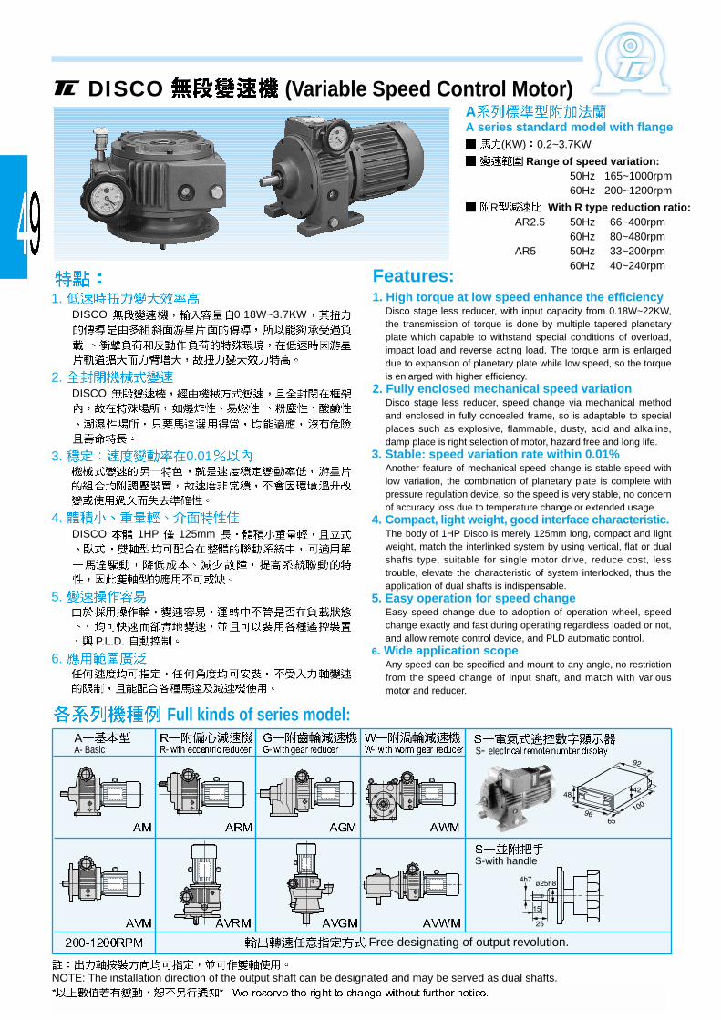
1. DISCO 0.18W~3.7KW
2. DISCO
3. 0.01
4. DISCO 1HP 125mm
5.
P.L.D.
6.
1. High torque at low speed enhance the efficiencyDisco stage less reducer, with input capacity from 0.18W~22KW,the transmission of torque is done by multiple tapered planetaryplate which capable to withstand special conditions of overload,impact load and reverse acting load. The torque arm is enlargeddue to expansion of planetary plate while low speed, so the torqueis enlarged with higher efficiency.
2. Fully enclosed mechanical speed variationDisco stage less reducer, speed change via mechanical methodand enclosed in fully concealed frame, so is adaptable to specialplaces such as explosive, flammable, dusty, acid and alkaline,damp place is right selection of motor, hazard free and long life.
3. Stable: speed variation rate within 0.01%Another feature of mechanical speed change is stable speed withlow variation, the combination of planetary plate is complete withpressure regulation device, so the speed is very stable, no concernof accuracy loss due to temperature change or extended usage.
4. Compact, light weight, good interface characteristic.The body of 1HP Disco is merely 125mm long, compact and lightweight, match the interlinked system by using vertical, flat or dualshafts type, suitable for single motor drive, reduce cost, lesstrouble, elevate the characteristic of system interlocked, thus theapplication of dual shafts is indispensable.
5. Easy operation for speed changeEasy speed change due to adoption of operation wheel, speedchange exactly and fast during operating regardless loaded or not,and allow remote control device, and PLD automatic control.
6. Wide application scopeAny speed can be specified and mount to any angle, no restrictionfrom the speed change of input shaft, and match with variousmotor and reducer.
AA series standard model with flange
(KW) 0.2~3.7KW
Range of speed variation:50Hz 165~1000rpm60Hz 200~1200rpm
R With R type reduction ratio:AR2.5 50Hz 66~400rpm
60Hz 80~480rpm AR5 50Hz 33~200rpm
60Hz 40~240rpm
DISCO (Variable Speed Control Motor)
Features:
Full kinds of series model:
NOTE: The installation direction of the output shaft can be designated and may be served as dual shafts.
AA- Basic
Free designating of output revolution.
S- elec
S-with handle

B C H I V LA LB LC LE LG LN LZOutput shaft size AV
Model S (h6) Q P U O (Kg)02AV(M) 110 66 198 153 99 110 130 160 3.5 10 4 10 11 23 5 5 M5 8.505AV(M) 138 87 220 174 110 110 130 160 3.5 12 4 12 14 30 5 5 M5 151AV(M) 152 103 251 205 129 130 165 200 3.5 12 4 12 19 40 6 6 M6 222AV(M) 190 120 295 241 157 130 165 200 4 16 4 15 24 50 8 7 M8 373AV(M) 220 147 357 295 187 180 215 250 4 16 4 15 28 60 8 7 M8
68725
L KOutput shaft size
Model S1 (h6) Q1 P1 U1 O1
02 A K 20577
14 30 5 5 M5
AV 200 11 25
05 A K 210 69 14 30 5 5 M5AV
1 A K 261 89 19 40 6 6 M6AV
2 A K 331 112 24 50 8 7 M8AV
3 A K 391 134 28 60 8 7 M85 AV
Horizontal type (Foot mounting)
Selection list for revolution of common output shaft
Vertical type (Flange direct coupling)
Dual shafts Type
AK AVK
AV (M)
A (M)
RPM)4P 60Hz 4P 50Hz Ratio Range of speed variation Model of reducer Code1200~200 1000~165 1/1.4~1/8.4 A Series AM AVM480~80 400~66 2.5 1/3.5~1/21 R
ARM AVRM240~40 200~33 5 1/7~1/42 R type: with eccentric reducer120~20 100~16.5 10 1/14~1/84 AGM80~13.3 66.6~11 15 1/21~1/126 AVGM60~10 50~8.3 20 1/28~1/16840~6.7 33.3~5.5 30 1/42~1/251 AWM
20~3.3 16.7~2.8 60 1/84~1/509 AVWM
CGWC type: with swing linear reducerG type: with gear reducerW type: with worm gear reducer
B C E F G H I J M N R V ZOutput shaft size A
Model S (h6) Q P U O (Kg)02A(M) 110 71 110 105 12 203 158 25 140 125 48 99 9 14 30 5 5 M5 805A(M) 138 90 120 105 15 223 177 32 160 135 60 110 10 14 30 5 5 M5 141A(M) 152 106 160 125 15 254 208 40 190 150 75 129 12 19 40 6 6 M6 202A(M) 190 125 180 140 18 300 246 50 230 165 100 157 12 24 50 8 7 M8 343A(M) 220 150 245 230 20 360 298 55 300 270 85 187 14 28 60 8 7 M8
63675
J J

2013/06
Tel: +886-2-22992655~59 Fax: +886-2-22990146 E-mail: [email protected]://www. tunglee. com.tw
Tel: +86-592-7899356~9 Fax: +86-592-7559311Tel: +86-512-5360-4758(68) Fax: +86-512-53601027Tel: +86-769-85083030~1 Fax: +86-769-85085955
Horizontal/Vertical type gear motorCE/EMC approved
(Horsepower):
0.1kw-3.7kw
(Ratio):
1/3-1/1800
Linear gear motor(Thrust): 1kg-140kg
(Strock Speed): 1-50 mm/sec
(Length): 100~600mm
Hollow-worm gear motor(Horsepower): 40w-2200w
(Ratio): 1/5-1/180
Variable Speed control motor
(Horsepower):
0.2kw-3.7kw
(Speed range):
200rpm-1200rpm
Planetary Reducer(Horsepower): 1/2HP-150HP
Speed control gear motor
Gear motor(Horsepower):
6w-150w(Ratio):
1/3-1/1800
Electromagnetic brake motor(Horsepower): 6-150w
(Ratio): 1/3-1/1800
Low backlash planetary gear reducer for servomotor
(Type): TRK-B.C.D.E.F
(Horsepower): 50w-5000w
(Ratio): 3-25
Low backlash planetary gear reducer for servo motor
(Mode)l : 042, 060, 090, 115, 142, 180
(Horsepower): 50w-5000w(Ratio): 3-100
Shaft-Mounted ReducerModel: TL-4060, 4070, 5080
(Ratio): 1/30~1/300
(Horsepower): 100w-1500w