the graphics subsystem of the vertical …
TRANSCRIPT
THE GRAPHICS SUBSYSTEM OF THE VERTICAL WORKSTATIONOF THE AUTOMATED MANUFACTURING RESEARCH FACILITY
AT THE NATIONAL BUREAU OF STANDARDS
Dr. Thomas R. KramerGuest Researcher, National Bureau of Standards, &
Research Associate, Catholic University
May 19, 1988
NBSIR 88-3783
Funding for the research reported in this paper was provided to Catholic University under GrantNo. 60NANB5D0522 and Grant No. 70NANB7H0716 from the National Bureau of Standards.
Certain commercial equipment and software are identified in this paper in order to adequately spec-ify the experimental facility. Such identification does not imply recommendation or endorsementby the National Bureau of Standards, nor does it imply that the equipment or software identifiedare necessarily the best available for the purpose.
VWS Graphics
- i -
CONTENTS
Page
I. INTRODUCTION.................................................................................................................1 1. CONTENTS......................................................................................................................1 2. AUDIENCE ......................................................................................................................1 3. BRIEF VWS DESCRIPTION ..........................................................................................2 4. RELATED READING .....................................................................................................2
II. OVERVIEW ........................................................................................................................3 1. USES.................................................................................................................................3 2. APPEARANCE ................................................................................................................3 3. STRONG POINTS ...........................................................................................................5 4. WEAK POINTS ...............................................................................................................5
III. GENERAL APPEARANCE AND USE ............................................................................7 1. ARRANGEMENT OF THE DRAWING WINDOW ......................................................7 2. APPEARANCE OF A FEATURE ...................................................................................8 2.1. Introduction................................................................................................................8 2.2. Drawing Text and Contour_Grooves.........................................................................8 3. MASKING........................................................................................................................9 4. LOCATOR......................................................................................................................11 5. FLASHING.....................................................................................................................12 6. PICKING ........................................................................................................................12 7. REFRESHING THE SCREEN.......................................................................................12 8. WIPING OUT A PICTURE ...........................................................................................12
IV. OTHER GRAPHICS CAPABILITIES ............................................................................13 1. INTRODUCTION ..........................................................................................................13 2. DESIGN EDITOR ..........................................................................................................13 3. DATA EXECUTION MODULE ...................................................................................13 4. VWS_CADM..................................................................................................................14

VWS Graphics
- ii -
V. SOFTWARE TECHNIQUES AND ISSUES....................................................................15 1. DATABASE ...................................................................................................................15 2. MASKING VS. CLIPPING............................................................................................15 3. SCALING AND TRANSLATION WITH FUNCTION SWITCHES...........................15 4. POLYGON VS. LINE DRAWING................................................................................16 5. STORING AND RESTORING IMAGES......................................................................18 6. SUNCORE......................................................................................................................18 6.1. Using SunCore.........................................................................................................18 6.2. Advantages of SunCore ...........................................................................................18 6.3. Disadvantages of SunCore.......................................................................................18 7. MAINTAINING SEGMENT INDEXES .......................................................................20 8. GRAPHICS SUBSYSTEM CAPABILITIES NOT USED IN VWS2 ..........................21 8.1. Picking from Menu with Mouse ..............................................................................21 8.2. Automatic Stuffing of Position Data .......................................................................21 8.3. Use of Icons .............................................................................................................21 9. THE "FIX_GRAPHICS" FILE.......................................................................................22
VI. SOFTWARE.....................................................................................................................23 1. INTRODUCTION ..........................................................................................................23 2. HIGH LEVEL AND MISCELLANEOUS FUNCTIONS .............................................23 3. FEATURE AND SUBFEATURE DRAWERS .............................................................23 4. OTHER CONTOUR FEATURE AND TOOL PATH DRAWING FUNCTIONS .......23 5. FEATURE PROFILE AND OUTLINE DRAWERS.....................................................23 6. LOW LEVEL LINE, POLYGON, AND MASK DRAWERS.......................................24 7. FUNCTIONS THAT DEFINE FUNCTIONS................................................................24 8. INITIALIZATION, TERMINATION, AND LABELLING FUNCTIONS ..................24 9. DISPLAY MANIPULATION FUNCTIONS ................................................................24
REFERENCES ........................................................................................................................26

VWS Graphics
- iii -
LIST OF FIGURES
Page
Figure 1. Drawing of XYZ Part .................................................................................................4Figure 2. Drawing Text..............................................................................................................9Figure 3. Bits of Mask .............................................................................................................10Figure 4. Function Switches ....................................................................................................17

VWS Graphics
- iv -
LIST OF TABLES
Page
Table 1. Graphics Subsystem Software ..................................................................................25

- 1 -
THE GRAPHICS SUBSYSTEM OF THE VERTICAL WORKSTATIONOF THE AUTOMATED MANUFACTURING RESEARCH FACILITY
AT THE NATIONAL BUREAU OF STANDARDS
I. INTRODUCTION
1. CONTENTS
This paper discusses the graphics subsystem of the Vertical Workstation (VWS) ofthe Automated Manufacturing Research Facility (AMRF) at the National Bureau ofStandards. The descriptions pertain to the system in use during the summer of 1987.
Chapter II gives an overview of the graphics subsystem, its appearance, uses, strongpoints, and weak points.
Chapter III describes the arrangement of the drawing window, the appearance of thedrawing of a feature, how the drawing is covered with a grey mask, how finding partlocations is done, how the picture of a feature may be flashed, how the featurenumber of a feature may be found from the picture of the feature, how the drawingmay be refreshed, and how the drawing may be wiped out.
Chapter IV presents other graphics capabilities that are available only from certainparts of the system, namely, the Part Design Editor, the Data Execution module, andthe vws_cadm user interface.
Chapter V discusses several software techniques and issues: the database needed by the graphicssubsystem, the relative merits of masking vs. clipping, how function switches are used for scalingand translation, how using polygons compares with using lines in SunCore, when images are savedon disk or restored from disk, the pros and cons of SunCore, and the use of segment indexes. Thischapter also makes brief mention of some capabilities which were developed but are not currentlyin use. Finally, it discusses alterations to three pairs of SunCore functions.
Chapter VI gives a brief description of the software of the graphics subsystem.
2. AUDIENCE
The paper is intended to be useful to people interested in concepts and technicaldetails of the VWS, particularly AMRF personnel who are running the VWS ormaintaining or improving the software for the VWS. The paper is intended to beuseful also to other researchers in automated manufacturing. Knowledge of thecomputer language LISP and familiarity with computer graphics are useful but notessential to reading this paper. Detailed documentation of the LISP functions that

VWS Graphics
- 2 -
are involved with the systems described here is being prepared separately.

VWS Graphics
- 3 -
3. BRIEF VWS DESCRIPTION
The VWS is a computer-integrated automated machining workstation. It includes a controlsystem, a computer-aided design system, an automatic process planning system, and an automaticNC-code generator. The principal machinery is a milling center (Monarch VMC-75 with aGE2000 controller) and a robot (Unimate 4070 with a Val II controller) to tend the milling center.There is quite a bit of ancillary hardware. The system is controlled from a microcomputer (Sun 3/160 with 6Mb memory, BW monitor). Running in stand-alone mode, it is possible to design andmachine a simple metal part within an hour. The VWS may also be run as an integrated part of theAMRF. The workstation is described in more detail in [K&J1].
The software for the VWS is written in Franz LISP dialect of the computer language LISP. Anational standard graphics package named "Core" has been implemented for the Sun computer bySun Microsystems and named "SunCore". An interface between Franz LISP and SunCore waswritten by Franz, Inc. In this paper the VWS software is called the VWS2 system. SunCore (viathe Franz interface) is the graphics package on which the VWS2 Graphics Subsystem is built. Sixprincipal modules comprise the VWS2 system: the Production Management Operating System(the control system), the State Table Editor, the Equipment Program Generator, the Part DesignEditor, the Process Planner, and the Data Execution module.
The Part Design Editor, Process Planning and Data Execution modules, as well as other systemcapabilities, may be accessed by the user through a small user interface called vws_cadm.Vws_cadm asks the user questions about what the user wants to do and then activates theappropriate module or other capability accordingly.
To produce a part from scratch, the user sits at the Sun workstation and creates a design using thePart Design Editor. The Process Planner is then called to write a plan for how to machine a part ofthat design. Next NC-code is generated automatically from the design and the plan by the DataExecution module. Finally the user tells the control system to make the part. The control systemcoordinates the activities of the workstation equipment so that the part blank is loaded onto themilling machine, the NC-code is sent to the milling machine and executed (making the part), andthe finished part is unloaded.
To make a part using existing data, the VWS controller calls on the local database manager toretrieve several types of data: tray contents, VWS process plan, and NC-code. Following theprocess plan, the VWS controller directs workstation activity so that the robot loads the part ontothe milling machine, the NC-code is sent to the milling machine and executed, and the finished partis unloaded.
4. RELATED READING
This paper is one of about a dozen papers being prepared as part of the AMRF documentation todescribe all aspects of the VWS. The others are [JUN], [KRA1], [KRA3], [KRA4], [K&J2],[K&S2], [KR&W], [LOVE], [NA&J], and [RUDD]. Other papers, prepared for professionalmeetings, also describe the VWS [KRA2], [K&J1], and [K&S1].

VWS Graphics
- 4 -
II. OVERVIEW
1. USES
The graphics subsystem of the VWS2 system is used to display designs andworkpieces. The graphics subsystem is used by the Part Design Editor module todisplay designs, by the Data Execution Module to display workpieces, and directlyfrom the vws_cadm user interface to display designs and workpieces. The graphicssubsystem provides a few other capabilities, as well: displaying the appearance oftext fonts, displaying the position of a cursor, and drawing the path of the tools usedto machine a part.
The graphics subsystem is not under direct user control. Rather, the user interactswith the Design Editor or vws_cadm, and they control the graphics subsystem.
Hard copies of pictures made by the graphics subsystem may be made by screen dumps or by usingan advanced desktop publishing system such as Frame Maker or Interleaf to capture picturesdirectly from the computer screen. All such hard copies are bit images.
An expert user can make additional uses of the subsystem, such as drawing figures.In these uses the subsystem is under direct user control. The additional uses requiredetailed knowledge of LISP and SunCore and are not discussed further in this paper.
2. APPEARANCE
In all of its uses, the graphics subsystem shows three orthographic views of the itembeing displayed, as on a conventional mechanical drawing. The drawing is done ina window on the screen of the Sun computer terminal. The drawing is scaledautomatically according to the size of the item being displayed. The scale of thedrawing is not under control of the user, except that the user may use the standardSun window manipulation facilities to make the window bigger or smaller, move itaround, etc.
Figure 1 shows the graphics window as it appears in the design editor. Ademonstration part called the XYZ part is drawn in the figure.

VWS Graphics
- 5 -
Figure 1. Drawing of XYZ Part

VWS Graphics
- 6 -
3. STRONG POINTS
The graphics subsystem provides a decent representation of a design or workpiecefor the user. It draws quickly enough not to irritate the user. It requirescomparatively little user input to produce a fairly complicated picture. It is easy toget a hard copy.
When used in the Data Execution module, the graphics subsystem provides a goodsimulation of the machining process.
The subsystem provides the user with useful information. It can respond quickly andaccurately to questions like:
What change to the workpiece was made in step 10 of the process plan just executed?What is the feature number of the feature I am pointing at?What does feature 6 look like?What are the part coordinates of the point I am pointing at?What does the XYZ part look like?
4. WEAK POINTS
The graphics subsystem does not provide much user control of the picture. No three-dimensionalpictures, alternate views, cutaways, zooming, coloring, labelling with text, arrows, etc., or layering(features found on commercial CAD systems) are available.
The subsystem does not provide a true picture of the part when features intersect.The entire picture of each feature is drawn even if some or all of the feature is eatenaway by some other feature.
The VWS2 system does not provide device drivers for pen plotters or laser printersto make high-quality images.

VWS Graphics
- 7 -
VWS Graphics
- 8 -
III. GENERAL APPEARANCE AND USE
1. ARRANGEMENT OF THE DRAWING WINDOW
The graphics subsystem, is part of a LISP process running in a window under the "Suntools"window environment. When a picture is to be created, the LISP process creates a new core toolcovered by a graphics window in the upper left-hand corner of the screen. All the drawingcommands given from the LISP process are directed to this window. Figure 1 shows the normalscreen layout and should be used for reference in reading the rest of this section.
The initial window size is 746 by 670 pixels. The subsystem is tuned to this window size, in thesense that the best picture is made when the window is that size. The window size was selectedseveral years ago as a convenient size to fit in an overall window layout. This size does notoptimize anything, but it does not present any particular difficulties, either. The window may bemade about 50 percent larger or 10 percent smaller (by using the Suntools window manipulationfacilities) without creating any glaring defects in the picture.
The reason that changing the window size changes more than the size of the pictureis that for a fixed linewidth setting, the number of pixels in the width of a line varieswith the size of the window. The most common linewidth used in the subsystemresults in lines that are three pixels wide in the 746 by 670 window. If the size of thewindow is increased, some lines will jump to five pixels wide, depending upon theangle of the line with the horizontal, while other lines will remaing at three pixelswide. This degrades the quality of the picture.
The scale of the picture is calculated automatically. A fixed space is allotted into which the pictureof the part must fit. The subsystem determines how to fit the block on which the part is based intothe allotted space so as to make the largest possible picture. First, the block is fitted so as to useup all the horizontal space. If this makes a picture that is too tall to fit vertically, it scraps thehorizontal fit and fits the block vertically, instead. The scale of graphics coordinate units per inchis determined according to the fit.
A grid of dotted lines somewhat like a piece of graph paper is drawn next. The areacovered by the grid is held within narrow limits, but the size of a single grid square(and hence the number of grid lines), varies with the size of the block so as to keepthe number of pixels per grid square in a reasonable range. The scale of inches pergrid line also varies, but is always a multiple of 2. In other words, acceptable valuesfor inches per grid line are chosen from the sequence (. . . 4, 2, 1, 1/2, 1/4, 1/8 . . .).There is no maximum or minimum.
Three views of the blank block from which the part will be made are placed on the grid, and thescene is labelled. The three views are placed so that the top view is directly above the front viewand the side view is directly to the right of the front view. Thus, the grid lines may be used to match

VWS Graphics
- 9 -
corresponding views of the same feature. A 45 degree oblique line is drawn directly to the right ofthe top view of the block and directly above the side view. The oblique line is used along with thegrid lines to match corresponding views of a feature on the top view and the side view.

VWS Graphics
- 10 -
At the top of the window on the left, three to five lines of text identify:A. The module or facility using the subsystem ("Design Editor" in Figure 1).B. The name of the design or workpiece ("XYZ" in Figure 1) - both if the Data
Execution Module is in charge.C. The current setting of the verification system ("on soft" in Figure 1).D. The name of the file to which NC-code is being written, when the Data
Execution Module is run with graphics and NC-coding turned on.
At the top right of the picture in the Design Editor, either pictures of fonts or position informationappear from time to time. Fonts are showing in Figure 1.
2. APPEARANCE OF A FEATURE
2.1. Introduction
The graphics subsystem makes a picture by drawing features and subfeatures on the three views ofthe block (the one exception being the thread subfeature, which does not appear on the top view).This is followed in some cases by masking out portions of the block which have been completelymilled away. Each view of a feature is a silhouette of the feature, in which just the outline of thefeature is visible.
Except for three subfeatures (countersink, chamfer_in, and chamfer_out), the drawing of whichmodifies the appearance of the parent feature, each feature is drawn as though it were the onlyfeature on the part. The lines created by the intersection of features are not drawn, and the linesdestroyed by machining over an existing feature are not removed.
All features that are legitimate (in the sense that the verification system says they are OK), will bedrawn correctly. Features that fail verification may be incorrectly drawn. Pockets whose right sideis to the left of the left side look quite peculiar, for example.
Dozens of examples of the appearance of features and subfeatures are given in Chapter II of[K&J2].
2.2. Drawing Text and Contour_Grooves
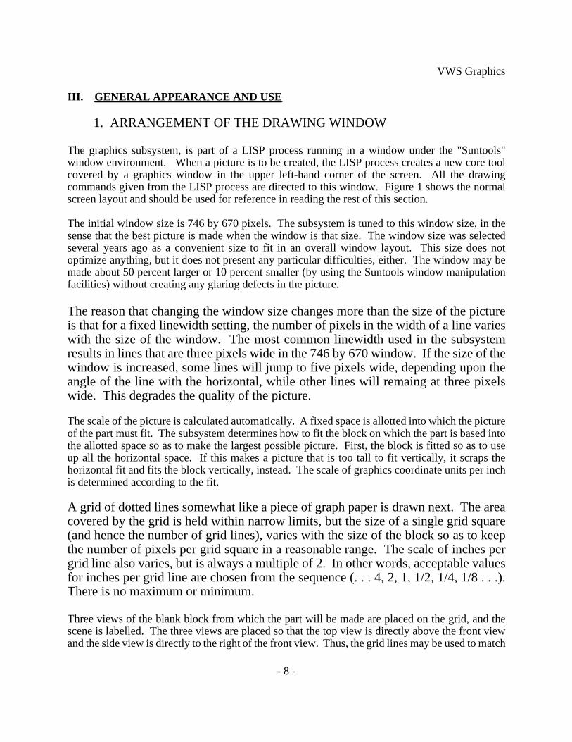
All but two features are drawn with thin (1 to 3 pixel wide) lines. The two exceptions are the textand contour_groove features, which are drawn with polygons. Text and contour_groove featuresare likely to overlap themselves. Determining the actual outline of an arbitrary contour_groove isa formidable task that has not been undertaken in the VWS2 system.
Fortunately, a little drawing trickery makes an accurate picture of the outline without anycalculation of the outline required. The technique is to draw the feature twice, first with a set ofblack polygons, and then again with a set of slightly narrower white polygons. The black thatremains at the end is a correct outline.
The technique is illustrated in Figure 2. In Figure 2 the letter A is drawn three times. On the left,it is drawn as it would appear if the outlines of all three parts of it were drawn separately. On theright it is shown in black as it appears after the first stage of the actual drawing. In the middle it is
VWS Graphics
- 11 -
shown as appears when the drawing is finished. Notice that since the drawing is made withpolygons, the grid lines that pass behind the middle view are covered up by the interior of the A.
The grid lines can be restored by refreshing the picture, but if there were outlines ofany other features underneath the middle A, they would have been covered up, also,even if they should appear. This is a slight drawback of this method of outlinedrawing.
3. MASKING
As may be seen from Figure 1, the three views of a part appear to be drawn againsta grey background. This appearance is an illusion. The grey is actually drawn overthe top of the part. The grey areas of a picture form a mask that covers up portionsof features. The grid and the labels are drawn on top of the mask.
When the picture of a block with no features is generated (this is the first step in allpictures), a "main mask" is generated. The main mask appears to be a rectangularpolygon with three holes in it, one for each of the three views of the block. Actually,the main mask is an odd-shaped polygon with no holes (SunCore does not includethe ability to draw polygons with holes).
When features are added that go all the way through the block or cut all the way across it on thefront or side view, additional grey polygons are generated which cover up more sections of the
Figure 2. Drawing Text

VWS Graphics
- 12 -
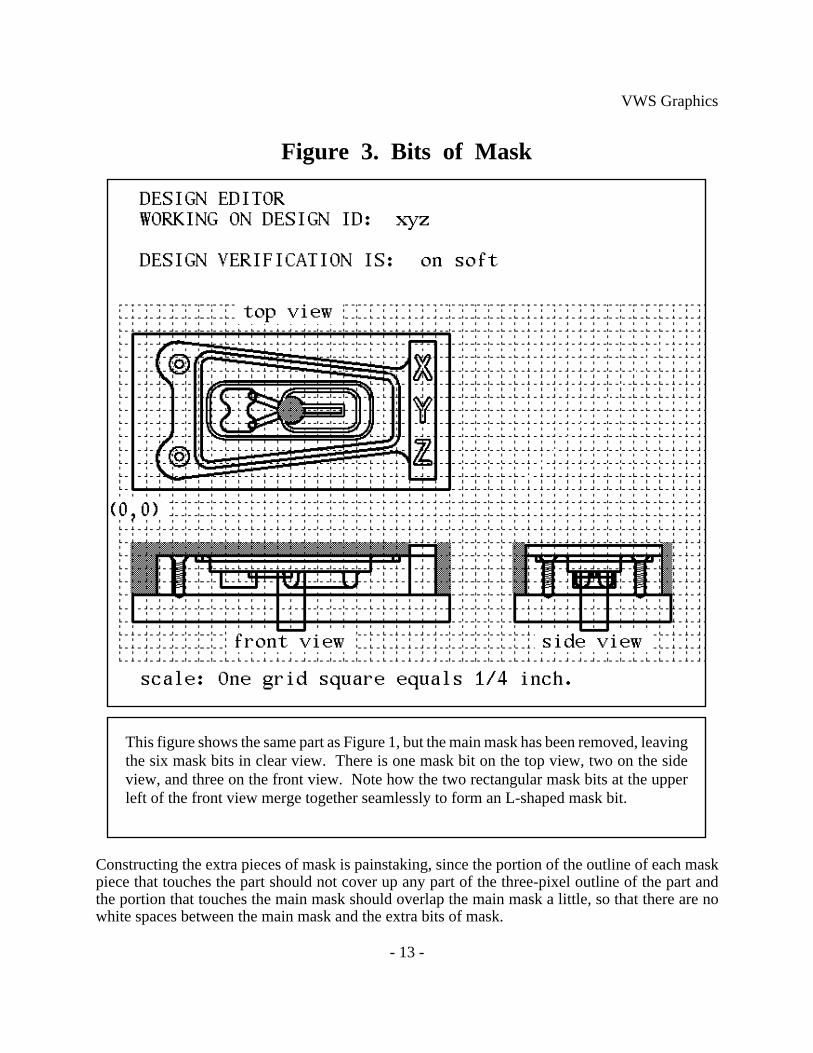
block. The grey circle on the top view of the part in Figure 1 is an example. It indicates a throughhole. When these additional bits of mask are on the periphery in any of the views, they blend(almost) seamlessly with the main mask and with each other to give a clear picture of the newoutline of the part. Figure 3 shows the same part as Figure 1, but the main mask has been deleted.The grey patches on Figure 3 are the extra bits of mask required by this drawing.
VWS Graphics
- 13 -
Constructing the extra pieces of mask is painstaking, since the portion of the outline of each maskpiece that touches the part should not cover up any part of the three-pixel outline of the part andthe portion that touches the main mask should overlap the main mask a little, so that there are nowhite spaces between the main mask and the extra bits of mask.
Figure 3. Bits of Mask
This figure shows the same part as Figure 1, but the main mask has been removed, leavingthe six mask bits in clear view. There is one mask bit on the top view, two on the sideview, and three on the front view. Note how the two rectangular mask bits at the upperleft of the front view merge together seamlessly to form an L-shaped mask bit.
VWS Graphics
- 14 -
To accomplish this, the outline of each mask bit must be retracted an average of 1.5pixels from the part and extended into the main mask at least two pixels. Because ofrounding, the main mask and the extra bits will occasionally be one pixel removedfrom their proper location.
The masks are kept in the subsystem’s data base as a series of polygon commands.Polygon commands are added to the data base or deleted from it each time a featureis added or deleted. In the Design editor, the mask is not redrawn automatically eachtime a feature is drawn, because this would be too time consuming. Two editorcommands ("group" and "array") always redraw the mask, but normally the usermust use the "rdraw" command to see the current mask. An indexing system is usedto keep track of which pieces of mask go with which features.
The masking system is not smart enough to know that the mask should be changedif two or more features combine to remove material all the way across the block onthe front or side view.
4. LOCATOR
The Design Editor includes a command named "loc". This command prompts the user to use themouse to point at the picture and press the right mouse button. When the right button is pressed, across-hair is displayed at the position of the mouse cursor, and the location of the point picked isshown in the upper right corner of the picture, given in part coordinates (including the name of theview of the part in which the cross-hair is located). Position information is rounded off to thenearest eightieth of an inch.
Additional information about "loc" is given on page 94 of [K&J2] and pages B-33 and B-34 of[KRA4].

VWS Graphics
- 15 -
5. FLASHING
The graphics subsystem can flash the picture of a feature or subfeature on and off.Flashing is done automatically in the Design Editor when the user elects to changeor delete a feature. Flashing is done automatically after a successful pick, asdescribed in the next section. Flashing is done under user control in the DesignEditor by using the "flash" command, as described on page 94 of [K&J2] and pageB-24 of [KRA4].
The change in the picture of a part resulting from the execution of a step of a process plan may beflashed by breaking into LISP when a picture which was drawn by the Data Execution module ison the screen and giving the LISP command (flash_step n), where n is the number of the step theuser wants to see.
Feature flashing may be done on a picture drawn by the Data Execution module by giving the LISPcommand (flash_feature n), where n is the number of the feature the user wants to see.
6. PICKING
If, while using the Design Editor, a user wants to know the feature number of a feature drawn onthe screen, the "pick" command will do it. After calling the "pick" command, the user points at thefeature with the mouse and pushes a button. The number of the feature is printed in the commandscreen. This is described in more detail on page 95 of [K&J2] and page B-41 of [KRA4].
7. REFRESHING THE SCREEN
The appearance of a picture may be degraded by deleting features (which leaves white patches),by adding features (so that the mask gets out of date), by using the locator (which puts cross-hairson the picture), by using the Suntools redisplay facility (which puts the features on top of the mask),or other ways. To get the picture clean to the best of the graphics subsystem’s ability, the user maycall the "rdraw" command of the Design Editor, or break into LISP and give the command(refresh_part_display). More information about this is given on page 95 of [K&J2] and page B-43of [KRA4].
8. WIPING OUT A PICTURE
The picture created by the Design Editor may be wiped out by turning graphics off.See page 94 of [K&J2] and page B-27 of [KRA4]. When the user quits the DesignEditor any existing picture is automatically wiped out.
From vws_cadm a picture may be wiped out by using the "ge" command (short for graphics erase)of the output facility. See page A-28 of [KRA4].

VWS Graphics
- 16 -
A picture may also be wiped out by breaking into LISP and giving the command(close_part_display).
VWS Graphics
- 17 -
IV. OTHER GRAPHICS CAPABILITIES
1. INTRODUCTION
Some capabilities of the graphics subsystem not mentioned in Chapter III areavailable from only one of: the Design Editor, the Data Execution module, and thevws_cadm user interface. These follow.
2. DESIGN EDITOR
The Design Editor includes a "draw" command which may be used to regenerate thepicture of a feature even if the feature has not been changed. It is described on page94 of [K&J2] and page B-20 of [KRA4].
It also includes a "block" command, which will wipe out any existing picture anddraw a block with no features. See page 94 of [K&J2] and page B-10 of [KRA4].
In helping the user specify a contour outline, the graphics subsystem willautomatically draw a "frame" for the outline. The frame is wiped out when the userfinishes specifying the outline. Some frames are shown on page 65 of [K&J2].
3. DATA EXECUTION MODULE
In the Data Execution module, the picture is drawn by showing what each machiningoperation does. This differs from design drawing in that producing a feature mayrequire more than one operation. For example, a countersunk, threaded hole requiresat least three operations: a hole-making operation (which may be either "drill_hole"or "mill_pocket"), a "machine_countersink" operation, and a "tap_thread" operation.In the Design Editor, the thread and the countersink appear on the picture as soon asthe hole is drawn. In the Data Execution module, typically, there may be severalother things drawn between the making of a hole and its countersinking or tapping.If a workpiece is being partially machined (leaving out the thread), only the hole andcountersink would be drawn.
output

VWS Graphics
- 18 -
4. VWS_CADM
Four graphics capabilities are available from the vws_cadm user interface. These aredescribed in detail on pages 8 and A-23 through A-28 of [KRA4]. One of these,wiping out the picture, was described in section 8 of the last chapter.
A second capability, drawing the path of the tool, is available from vws_cadm onlywhen a picture drawn by the Data Execution module is still on the screen after theData Execution module wrote an NC-code file. In addition to the descriptionreferenced above, Chapter 12 of [K&S2] discusses tool path drawing.
The third graphics capability available from vws_cadm is drawing a workpiece, andthe fourth is drawing a design. The design drawing capability is separate from theDesign Editor and gives no opportunity for changing a design. It is usuallypreferable to fire up the editor for looking a design.

VWS Graphics
- 19 -
V. SOFTWARE TECHNIQUES AND ISSUES
1. DATABASE
The graphics subsystem uses the property list of the LISP atom "drawp" to storeinformation it needs on a continuing basis. Sixteen properties are kept. Adescription of LISP hierarchical property lists is given in Chapter II, section 2.5 of[KRA3]. A description of the details of the property list of "drawp" is given inChapter IV, section 3 of the same paper. Three of the items in the database aredescribed in section 7 below.
2. MASKING VS. CLIPPING
As discussed in section 3 of Chapter III, masking is used to create the appearancethat the part is in front of a grey background. One of the benefits of masking is thatif a feature extends off the side of the block in any of the views, so that part of thefeature appears to be hanging in midair, the portions of the feature that go off theblock are covered up by the mask. Another way of dealing with such features wouldbe to calculate where the feature runs off the block and not draw the portions of anylines that lie outside the block. This is called "clipping", since the process is liketaking a scissors and clipping off any lines that stick out.
Several clipping algorithms were written and implemented during the developmentof the graphics subsystem, but the routines only clipped lines that ran off a set ofrectangles. In order to draw correctly, the clipping routines would have to be able toclip any line extending outside of an arbitrary outline. This involves a great deal ofcalculation and was not undertaken.
3. SCALING AND TRANSLATION WITH FUNCTION SWITCHES
The graphics subsystem is constructed so that drawing commands use x, y, and z values expressedin part coordinates, not in SunCore’s world coordinates for the drawing window. To do this, thegraphics subsystem must be able to do scaling and translation automatically. Moreover, the samedrawing commands may be used on each of the three views of the part. These capabilities areimplemented as follows.
When the subsystem initializes a picture, it defines a set of drawing functions foreach of the three views of the part (top, front, and side). Each set has five primitivedrawing functions in it, one for drawing a straight line to a specific point, one fordrawing a straight line by moving incrementally, one for moving to a specific pointwithout drawing, one for moving incrementally, and one for drawing an arc. The
VWS Graphics
- 20 -
correct translation and scaling numbers for the view are hard coded into theseprimitive functions. Actually, since the scale is the same for all three views, the sameincremental draw and move functions work for all three views.
When drawing is to be done on a particular view, a command is given which redefines threefunctions - view_line_abs, view_move_abs, and view_arc - by assigning the definition alreadygenerated for the corresponding primitive in the appropriate view. For example, to draw on the topview, the LISP command (draw_top_view) is given, and:
A. the definition of view_line_abs is automatically set to the definition of view_line_top.B. the definition of view_move_abs is automatically set to the definition ofview_move_top.C. the definition of view_arc is automatically set to the definition of arc_top.
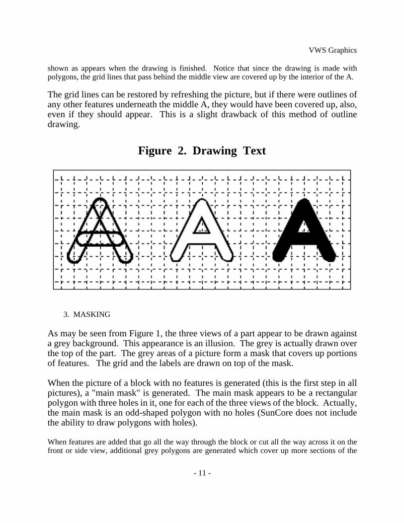
The image best associated with this process is that of a large switch with three barsand three positions. By moving the handle to one of the three positions, the juice foreach of three functions is drawn from one of three sources. This is shownschematically in Figure 4.
Using these function switches has two benefits: fewer parameters have to be passedto do a drawing and the functions run faster than if parameters were used, since thevalues are hard-coded.
Two other functions might have been included in this function switch setup but haveremained in the old form that requires parameter passing. These are for drawingpolygons in the shape of crescents and bars and are called view_crescent andview_bar.
4. POLYGON VS. LINE DRAWING
SunCore draws with lines that are an odd number of pixels wide. Most of the linesmade by the graphics subsystem are three pixels wide when the window is normalsize, but some use is made of 1 and 2 pixel wide lines. Lines 2 pixels wide are madein the subsystem by whiting out one pixel worth of a 3-pixel wide line - an awkwardmethod, at best.
SunCore lines are rounded with semicircles at the ends, so that they potentiallymimic the pattern left by a cutting tool in a milling machine quite well.Unfortunately, they do not live up to the potential.
Earlier versions of the graphics subsystem used lines to represent text andcontour_grooves. In the current version of the subsystem, text and contour_grooves
VWS Graphics
- 21 -
are made by using polygons. The change was made for three reasons. First, SunCorelines are all an odd number of pixels wide, so that line widths increase by jumps oftwo pixels, making a less accurate picture than with polygons, which can be madewider in increments of one pixel. Second, although line widths are expressed aspercentages of screen width, it is difficult to scale them correctly; the scaling doesnot turn out quite as expected. Third, arcs made with a series of lines have whiskersone to three pixels long that stick out normal to the arc, if the line is five or morepixels wide. This is apparently a bug in SunCore. Polygons have no whiskers.
In addition, polygon drawing seems to be slightly faster than line drawing. This issurprising since more than twice as many calculations must be done in LISP todescribe the outline of a polygon as to describe the center line of the polygon.

VWS Graphics
- 22 -
Figure 4. Function Switches
arc_rt
arc_ft
view_arc
input
FRONT
RIGHT
This figure shows a schematic view of function switches. Imagine that the threefunctions, view_move_abs, view_line_abs and view_arc, (shown as circles above) areconnected together by a bar with handles on the ends (shown with vertical stripes above).The bar slides up and down vertically.
The definitions of view_move_abs, view_line_abs, and view_arc are determined by theposition of the bar. In the front position, the definition of view_move_abs is thedefinition of move_abs_ft, the definition of view_line_abs is the definition of line_abs_ft,and the definition of view_arc is the definition of arc_ft.
The command "draw_top_view" moves the bar to the top position, "draw_right_view"moves the bar to the right position, and "draw_front_view" moves it to the front position(where it is shown above).
move_abs_rt line_abs_rt
move_abs_ft line_abs_ft
view_move_abs view_line_abs
input input
output output
move_abs_topTOP arc_top line_abs_top

VWS Graphics
- 23 -
5. STORING AND RESTORING IMAGES
SunCore includes the capability of storing graphics segments in disk files and restoring them whendesired. The graphics subsystem uses this capability for only one purpose: displaying fonts. Thepicture of five fonts shown at the upper right of Figure 1 is stored in a single graphics segment ondisk. Whenever a window is created by the subsystem, this segment is restored, bringing it intoon-board memory. From there, its visibility is turned on and off as necessary.
6. SUNCORE
6.1. Using SunCore
The SunCore software used in the graphics subsystem is incorporated into Franz Lisp through aninterface written by Franz, Inc. The interface is good, but has not been updated in several years.One SunCore function, "set_pick", that is required by the subsystem for picking features is notincluded in the Franz interface. It is brought into the LISP environment when the environment isbuilt by calling "getaddress" after SunCore is loaded.
SunCore functions are called from LISP by using the name of the SunCore function, as given inthe users manual, with the prefix "sc:".
6.2. Advantages of SunCore
SunCore is a very powerful graphics package. It supports two or three-dimensionalgraphics. The VWS2 graphics subsystem makes use of only the two-dimensionalcapabilities. SunCore requires the user to draw in segments. Each segment has aname and may have many drawing primitives (lines, polygons, etc.) in it. Segmentsmay be turned on and off, stacked one on top of another, saved and restored,transformed several ways, clipped several ways, and picked with the mouse.
SunCore supports graphical input routines (picking, locating, and button sensing) sothat it may be used as the basis for user interactive graphics.
In summary, nearly all the tools a programmer might want to build a graphicsapplication package for the VWS2 system are available in SunCore.
6.3. Disadvantages of SunCore
SunCore’s has three distinct disadvantages: it is ornery, comparatively slow, and amemory hog.
Although SunCore is powerful, even after several years of programming with it, getting it to do
VWS Graphics
- 24 -
what is wanted always seems like wading through molasses. It is sensitive to the slightest error ininput data or usage in a program, and it usually gives no clue as to what is bothering it. Forexample, if given a fixed point number for an x or y coordinate when told to draw something (italways wants a floating point number for a coordinate), it is apt to do nothing but draw a dot at theorigin. It gives no error message and the manual gives no warning. Only after making this mistakeseveral times and wasting a lot of time does the programmer learn to recognize it quickly.
Using most of the capabilities of SunCore requires the programmer to go through several initiationsteps. An example is using the locator; three initiation steps are required: initialize_device,set_echo_surface, and set_echo. If an initiation step is skipped, the system usually sends a helpfulerror message when a function call is made to the desired capability, but it would have been muchnicer if the system would either always initiate all its capabilities itself, or would initiate whateverit needed the first time the capability was used. Barring that, just putting all the initiation in onefunction call would have been a straightforward matter.
Slowness is relative, of course, but a crude absolute measure is: does the user getirritated waiting for a drawing to be done. By this measure, the VWS2 graphicssubsystem is slow only for complicated contour features. The slowness may be inSunCore, it may be in the LISP-SunCore interface, or it may be in memorymanagement for SunCore.
In any event SunCore is much slower than lower level graphics packages, and it hasoften been tempting to try another package in order to get more speed. Fortunately,the speed of the Sun computer itself has increased so much over the past few yearsas new models have come out, that the speed of the VWS2 graphics subsystem hasincreased substantially even while the amount of calculation required of it has alsoincreased.
SunCore uses memory in the LISP environment. It takes more memory when it wants it, and(unlike LISP, which reclaims used memory that does not need to be saved) it never gives it back.If a design is made in the Design Editor which includes two or three complicated contour grooves(so that the picture of each groove requires 50 to 100 polygons), SunCore is apt to commandeertwo megabytes of memory, thus expanding the size of the LISP environment beyond its upper limitof 6Mb. This results in either a core dump, an error message, or a "goodbye" message from LISP,which then wipes itself out. It is not clear what SunCore is doing with all that memory, since itseems to be more than necessary by a factor of at least 10.
If the VWS2 system is run with graphics on for a few hours, even if relatively simplepictures are drawn, SunCore eventually uses up all the available space in the LISPenvironment. If the VWS2 system is run with graphics off, it does not grow morethan a few tenths of a megabyte beyond its original size (about 3.5 Mb).
The line-drawing bug and limitations mentioned in section 4 are minor

VWS Graphics
- 25 -
disadvantages.

VWS Graphics
- 26 -
7. MAINTAINING SEGMENT INDEXES
In order to manipulate the picture of a part correctly for operations like refreshing adrawing, flashing a feature, flashing a step, changing a feature, or deleting a feature,it is necessary to keep information about what graphics segments currently exist, andhow the graphics segments correspond to steps or features. This is done in thegraphics subsystem by keeping three data structures in the graphics database: asegment list, a feature index, and a step index.
The segment list property name is "segment_list" in the property list of "drawp". It is a simple listof all graphics segments currently in existence. Except for the font picture, which is named"drawp_fonts", the name of each segment is "drawp_n", where n is an integer. A segment counternamed "last_seg_no" is kept and incremented by one each time a new segment is drawn. The valueof the counter is used for n to generate the name of the new segment. When new segments aredrawn, they are added to the list. When existing segments are wiped out, they are deleted from thelist. Six segments have reserved names, as follows:
drawp_0 is used (and re-used) for position information.drawp_1 is the grid.drawp_2 is the labels, excluding the verification level.drawp_3 is the block.drawp_4 is the label giving the verification level.drawp_5 is the mask.
The step index property name is "step_index". The value of the property is a LISP disembodiedproperty list in which the property names are integers representing step numbers from a processplan, and the value of each property is the name of a segment (namely the one that depicts thatstep). Each step is drawn in at most one segment, so that this structure is feasible. Some steps,such as initialization, closing, and probing, are not drawn at all.
The feature index property name is "feature_index". The value of the property is a LISPdisembodied property list in which the property names are integers representing feature numbersfrom a design. The value of each property is a list of the names of the segments that depict thatstep. There will be one to three names in each list. A countersunk, threaded hole, for example, isdrawn in three segments even though it is a single feature.
In the Design Editor, the features of the design may be renumbered from time to time. A LISPfunction, "reseq_feat_index", is used to update the feature index whenever a renumbering offeatures is performed. The index is also updated whenever a feature is added or deleted.
VWS Graphics
- 27 -
8. GRAPHICS SUBSYSTEM CAPABILITIES NOT USED IN VWS2
8.1. Picking from Menu with Mouse
Routines based on SunCore for picking items from menu with the mouse have beenwritten and tested. They work, but they are slow compared with Suntools menus, forexample. The graphics subsystem does not use these routines.
It would be preferable to build an interface between LISP and the Suntools menucapabilities than to use menu facilities built on SunCore. This has not been done inthe VWS2 system.
8.2. Automatic Stuffing of Position Data
The location finding capability called "loc" in the Design Editor and based on the LISP graphicsfunction "show_position" prints information about the position of the mouse on the screen, ratherthan automatically recording the position information in the design. Since the show_positionfunction returns the position information, it would be feasible to stuff the information into a datastructure automatically. This is not done in the version of the graphics subsystem which isdocumented here. Extensive add-ons to the VWS2 system have been written, tested, and used,which do make use of automatic data stuffing. They have not been documented yet.
8.3. Use of Icons
A typical use of graphics input in many systems is to have the user give commands to the systemby pointing at a picture (called an icon) that represents the command, and pushing a button. TheVWS1 graphics subsystem, predecessor of the VWS2 graphics subsystem, was used by the VWScontrol system in this icon picking mode for a few months. The graphics subsystem displayed thepictures of several parts. The user would point at one with the mouse and press a button, and theVWS would make that part. That application also included a method of changing the menu oficons.
The VWS1 application of icons was effective but slow, and the capability was not frequently used,since after a part was picked, it normally took the system twenty minutes to an hour to make thepart before another part could be picked. This capability has not been incorporated in the VWS2system or its current enhancements. It could be restored easily if there is a need for it.
VWS Graphics
- 28 -
9. THE "FIX_GRAPHICS" FILE
After the graphics subsystem had been largely written using the normal definitions of SunCorefunctions, it was decided to improve the behavior of three pairs of functions:
A. initialize_device and terminate_deviceB. initialize_core and terminate_coreC. create_retained_segment and close_retained_segment
The standard SunCore version of one or both members of each of these pairs of functions will sendan error message if it is called at the wrong time. For instance, calling close_retained_segmentwhen no segment is open results in an error message.
It was desired to be able to call these functions without receiving error messages. To do this, the"fix_graphics.l" file was written. This file is loaded when the LISP environment is built. Whenthe instructions in the file are executed, the standard definitions of the six functions are saved undernew names, and the old function names get new definitions, which call the old definitions usingthe new names. The new function definitions check whether a call to the old function definition isactually required before making it. For instance, the new definition of close_retained_segmentchecks whether there is an open segment. If no segment is open, close_retained_segment doesnothing. If there is an open segment, the old definition is used to close it.
In order to make the appropriate checks, the information being checked had to be saved. This wasdone by creating a place to put data inside the definition of the first member of each pair offunctions, and updating the information whenever either member of the pair is called. In otherwords, calling either member of the pair redefines the first member slightly. For instance, callingcreate_retained_segment (when there is no open segment) redefines create_retained_segment toinclude the name of the newly created segment. If close_retained_segment is called later, itexamines the definition of create_retained_segment. If the name of a segment is found at thecorrect place in the definition, close_retained_segment closes the segment and redefinescreate_retained_segment by removing the name of the previously open segment.
Data is inserted in a function by placing a disembodied property list in the function definitionimmediately after the list of arguments to the function. Since the list of data is part of a functiondefinition, when the function is called, LISP interprets the list as a function and evaluates it.Protecting the data from evaluation could be done with the "quote" function, but has beenimplemented by placing an nlambda function named "data_in_def", which always evaluates to nil,at the head of the list. When LISP evaluates an nlambda function it does not evaluate its arguments,and nlambdas take any number of arguments.
Using a function definition to hold global data that changes may seem odd, but it works quite wellin LISP. Using the function definition itself to hold the data isolates the data from anything thatmay befall the rest of the system.
If the graphics subsystem had not already been largely built using the old function names, it wouldhave been better to use new function names for the new functions, rather than redefining the oldones.
VWS Graphics
- 29 -
VI. SOFTWARE
1. INTRODUCTION
The functions that make up the graphics software are listed in Table 1, where theyare divided in eight categories. A description of each category follows.
The functions of Table 1 are all from the subdirectory "draw2" in the directory ~kramer/vws2.Each of them is kept in a file with the same name as the functions, plus the suffix ".l", except forview_arc, view_line_abs, view_line_rel, view_move_abs, and view_move_rel. Those fivefunctions are redefined dynamically as described in section 3 of Chapter V.
The functions shown in Table 1 are called as required by other components of the VWS2 system:the Design Editor, the Data Execution module, and the vws_cadm user interface. Of course, anyof the functions may be used directly from LISP, but only the expert user should try such use.
2. HIGH LEVEL AND MISCELLANEOUS FUNCTIONS
The focal point for drawing in all but the Data Execution module is the "draw_feature" function.It draws a feature and any subfeatures the feature may have. It is called by "draw_object" (which,in turn is subordinate to "draw_design" and "draw_part") and by the Design Editor. In the DataExecution module, features and subfeatures are drawn separately by function calls to the graphicssubsystem made by the "execute_step" function, as described in section 3.2 in Chapter II of[KR&W].
3. FEATURE AND SUBFEATURE DRAWERS
There are twelve feature and subfeature drawers. Each of the nine features types(contour_groove, chamfer, contour_pocket, side_contour, groove, hole, pocket,straight_groove, and text) has its own drawing function. Three of the foursubfeatures (chamfer_in, countersink, and thread) have their own drawing functions.The chamfer_out subfeature uses the drawing routine for the chamfer feature.
4. OTHER CONTOUR FEATURE AND TOOL PATH DRAWINGFUNCTIONS
Three low-level functions are required for drawing contour features. The tool pathdrawing system also requires three functions.
5. FEATURE PROFILE AND OUTLINE DRAWERS
The top view of a feature in the graphics subsystem is called its outline. The front
VWS Graphics
- 30 -
and side views are called profile views. Except in simple cases, the feature andsubfeature drawers call on outline and profile drawing routines. There are fiveoutline drawers and seven profile drawers included in the software.
6. LOW LEVEL LINE, POLYGON, AND MASK DRAWERS
There are nine functions for constructing and drawing masking polygons (the seventhat have "mask" as part of their name in Table 1, plus "polygon" and "sector").
Nine low level functions do line drawing. As shown in Figure 4, nine more linedrawing functions are hidden behind the scenes to save the definitions of view_arc,view_line_abs, and view_move_abs needed for drawing on the three views. Nofunction calls are ever made to the nine hidden functions, however. In fact, since thedefinitions are LISP lists, saving the definitions could be accomplished by makingthe definitions be the values of global variables or the values of properties in aproperty list.
Three low level functions (polygon, view_bar, and view_crescent) are used to drawthe outline of text and contour_groove features.
7. FUNCTIONS THAT DEFINE FUNCTIONS
Four of the six functions that define functions (define_draw_funcs, draw_ft_view, draw_rt_view,and draw_top_view) were discussed in Chapter V, section 3.
To be sure the graphics subsystem makes a good simulation of the machining process whendrawing for the Data Execution module, some drawing parameters (the diameter of a hole, forexample) are taken from the description of the tool used in the process being drawn. Thedescription of the tool is extracted from the tooling database by the "get_desc_from_slot" function.In order to draw for other purposes, the graphics subsystem requires a partial description of animaginary tool. The "redefine_get_slot" function redefines "get_desc_from_slot" each time"draw_feature" is called so that "get_desc_from_slot" returns an appropriate imaginary descriptionwhen it is called by other drawing functions. When "draw_feature" is finished, it restores thenormal definition of "get_desc_from_slot".
8. INITIALIZATION, TERMINATION, AND LABELLING FUNCTIONS
Picture initialization is accomplished by "init_part_display", which calls eight subordinates. Thepicture is terminated by "close_part_display".
To do the initialization, "set_window" (which calls "makewindow") starts up thewindow and initializes all the devices needed. Then "find_scale" figures out how to

VWS Graphics
- 31 -
fit the three views of the part into the window. The block and grid are drawn by"draw_block" and "draw_grid". The labels are drawn by "draw_labels" and"draw_verify" (which is separate so that verification level information can bechanged without redrawing the whole picture).
9. DISPLAY MANIPULATION FUNCTIONS
These are the functions required for flashing, picking, deleting, displaying fonts, displayingposition information, refreshing the picture, and refreshing the mask, as described earlier in thispaper.

VWS Graphics
- 32 -
Table 1. Graphics Subsystem Software
Low Level Line, Polygon,and Mask Drawers
arcarc2
arc_side_viewlozenge
main_maskmask_contourmask_lozenge
mask_rectmask_sector
mask_trianglepolygon
put_masksector
view_arcview_bar
view_crescentview_line_absview_line_rel
view_move_absview_move_rel
Feature and SubfeatureDrawers
draw_cgdraw_chamf_indraw_chamf_out
draw_cpdraw_cs
draw_csinkdraw_groove
draw_holedraw_pocket
draw_straight_groovedraw_text
draw_thread
Functions that DefineFunctions
define_draw_funcsdraw_ft_viewdraw_rt_view
draw_top_viewredefine_get_slot
Picture Initialization,Termination, and
Labelling functions
close_part_displaydraw_blockdraw_grid
draw_labelsdraw_verifyfind_scale
init_part_displaymakewindowset_window
Display ManipulationFunctions
erase_featureflash_feature
flash_steppick_feature_num
refresh_part_displayremask
show_fontsshow_position
High Level andMiscellaneous Functions
arc_centerdraw_designdraw_featuredraw_maskdraw_objectdraw_part
inc_seg_noreseq_feat_indexset_fill_shading
Other Contour Featureand Tool Path Drawing
Functions
draw_cg_framedraw_cg_linesdraw_corner
draw_tool_depth_loopdraw_tool_path
draw_tool_path_seg
Feature Profile andOutline Drawers
cg_outlinechamf_profilechar_outlinecontour_tracegroove_profile
hole_profilepocket_profile
stg_outlinetext_ft_profiletext_outline
text_rt_profilethread_profile
VWS Graphics
- 33 -
REFERENCES
[JUN]Jun, Jau-Shi; "The Vertical Machining Workstation Systems"; to be published as anNBSIR; 1987.
[KRA1]Kramer, Thomas R.; "Process Plan Expression, Generation, and Enhancement forthe Vertical Workstation Milling Machine in the Automated ManufacturingResearch Facility at the National Bureau of Standards"; NBSIR 87-3678; NationalBureau of Standards; 1987; 56 pages.
[KRA2]Kramer, Thomas R.; "Process Planning for a Milling Machine from a Feature-Based Design";Proceedings of Manufacturing International Meeting; Atlanta, Georgia; April 1988; ASME; 1988;Vol. III, pp. 179 -189.
[KRA3]Kramer, Thomas R.; "Data Handling in the Vertical Workstation of the Automated ManufacturingResearch Facility at the National Bureau of Standards"; NBSIR 88-3763; National Bureau ofStandards; 1988; 62 pages.
[KRA4]Kramer, Thomas R.; "The vws_cadm User Interface in the Vertical Workstation of the AutomatedManufacturing Research Facility at the National Bureau of Standards"; NBSIR 88-3738; NationalBureau of Standards; 1988; 110 pages.
[K&J1]Kramer, Thomas R.; and Jun, Jau-Shi; "Software for an Automated Machining Workstation";Proceedings of the 1986 International Machine Tool Technical Conference; September 1986;Chicago, Illinois; National Machine Tool Builders Association; 1986; pp. 12-9 through 12-44.
[K&J2]Kramer, Thomas R.; and Jun, Jau-Shi; "The Design Protocol, Part Design Editor, and GeometryLibrary of the Vertical Workstation of the Automated Manufacturing Research Facility at theNational Bureau of Standards"; NBSIR 88-3717; National Bureau of Standards, 1988; 101 pages.
[K&S1]Kramer, Thomas R.; and Strayer, W. Timothy; "Error Prevention in Data Preparation for aNumerically Controlled Milling Machine"; Proceedings of 1987 ASME Annual Meeting; ASME;1987; PED-Vol. 25, pp. 195 - 213.
VWS Graphics
- 34 -
[K&S2]Kramer, Thomas R.; and Strayer, W. Timothy; "Error Prevention and Detection in DataPreparation for the Vertical Workstation Milling Machine in the Automated ManufacturingResearch Facility at the National Bureau of Standards"; NBSIR 87-3677; National Bureau ofStandards; 1987; 61 pages.
[KR&W]Kramer, Thomas R.; and Weaver, Rebecca E.; "The Data Execution Module of the VerticalWorkstation of the Automated Manufacturing Research Facility at the National Bureau ofStandards"; NBSIR 88-3704; National Bureau of Standards; 1988; 58 pages.
[LOVE]Lovett, Denver; "Equipment Controllers of the Vertical Workstation"; NBSIR 88-3769; NationalBureau of Standards; 1988.
[NA&J]Nakpalohpo, Ibrahim; and Jun, Jau-Shi; "Automated Equipment Program Generatorand Execution System of the AMRF Vertical Workstation"; not yet published; 1987;17 pages.
[RUDD]Rudder, Frederick; (a paper in preparation describing the VWS hardware and software for the HP-9000 workstation supervisor); to be published as an NBSIR; 1988.
[SUNC]"SunCore Reference Manual"; Sun Microsystems; Part No: 800-1257-03; RevisionG of 17 February 1986; 223 pages.