the graded exams will be returned next tuesday, oct 4. you will have until the next class on...
TRANSCRIPT
The graded exams will be returned next Tuesday, Oct 4. You will have until the next class on Thursday, Oct 6 to rework the problems you got wrong and receive 50% added credit. Make sure you are in class as you will no have another opportunity to rework the exam. I will be going over the answers in class on Thursday. This will also be your only opportunity to ask for corrections/clarifications on any grading mistakes.
The homework assignment will be on line this afternoon but will not be due until Tuesday, Oct 11. This will give you the opportunity to start work on the problems so that you will not be overloaded with homework and the exam rework next week.
Energy Storage in Capacitors Electric Field Energy
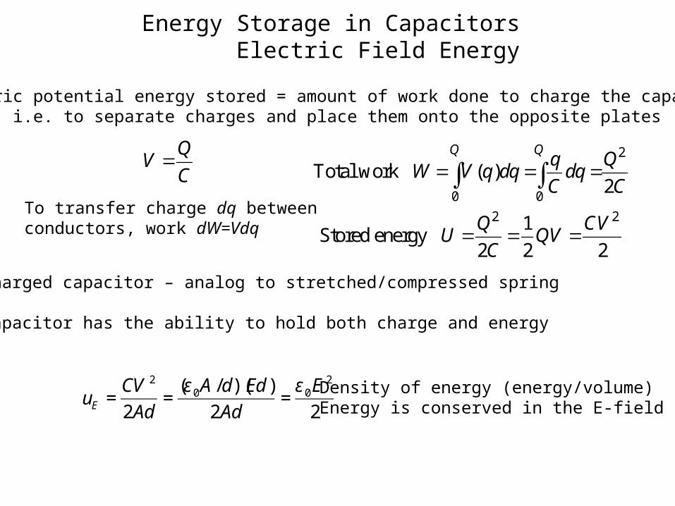
Electric potential energy stored = amount of work done to charge the capacitori.e. to separate charges and place them onto the opposite plates
QV
C 2
0 0
2 2
Total work ( )2
1Stored energy
2 2 2
Q Qq Q
W V q dq dqC C
Q CVU QV
C
Charged capacitor – analog to stretched/compressed spring
Capacitor has the ability to hold both charge and energy
To transfer charge dq between conductors, work dW=Vdq
Density of energy (energy/volume)Energy is conserved in the E-field
€
uE =CV 2
2Ad=
(ε 0A /d)(Ed)
2Ad=ε 0E
2
2
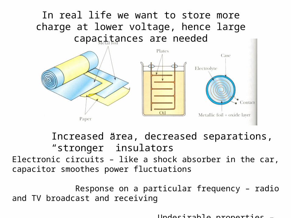
In real life we want to store more charge at lower voltage, hence large capacitances are needed
Increased area, decreased separations, “stronger” insulators
Electronic circuits – like a shock absorber in the car, capacitor smoothes power fluctuations
Response on a particular frequency – radio and TV broadcast and receiving
Undesirable properties – they limit high-frequency operation
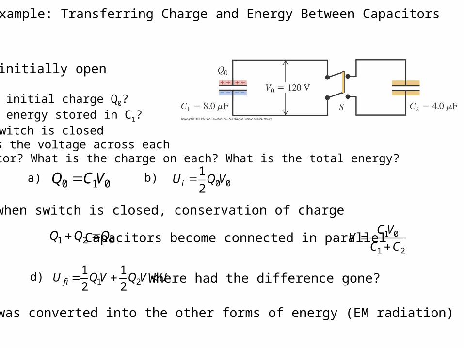
Example: Transferring Charge and Energy Between Capacitors
Switch S is initially open
1) What is the initial charge Q0?2) What is the energy stored in C1?3) After the switch is closed what is the voltage across each capacitor? What is the charge on each? What is the total energy?
a) 0 1 0Q CV 0 01
2iU Q Vb)
c) when switch is closed, conservation of charge
1 2 0Q Q Q Capacitors become connected in parallel 1 0
1 2
CVV
C C
d) 1 21 1
2 2f iU QV Q V U Where had the difference gone?
It was converted into the other forms of energy (EM radiation)
Definitions
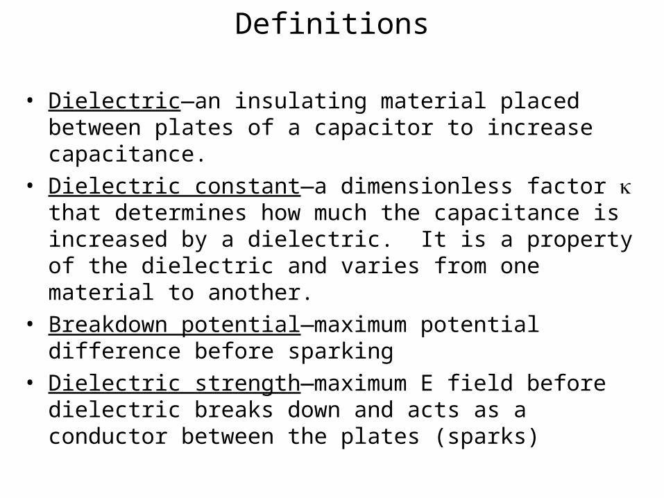
• Dielectric—an insulating material placed between plates of a capacitor to increase capacitance.
• Dielectric constant—a dimensionless factor that determines how much the capacitance is increased by a dielectric. It is a property of the dielectric and varies from one material to another.
• Breakdown potential—maximum potential difference before sparking
• Dielectric strength—maximum E field before dielectric breaks down and acts as a conductor between the plates (sparks)
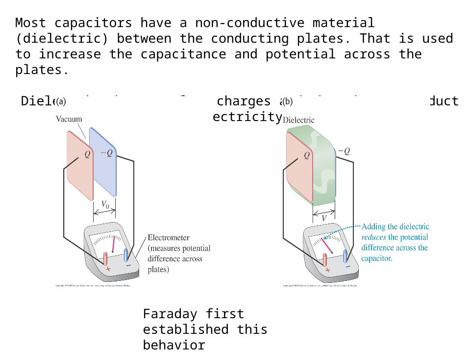
Most capacitors have a non-conductive material (dielectric) between the conducting plates. That is used to increase the capacitance and potential across the plates.
Dielectrics have no free charges and they do not conduct electricity
Faraday first established this behavior
Capacitors with Dielectrics
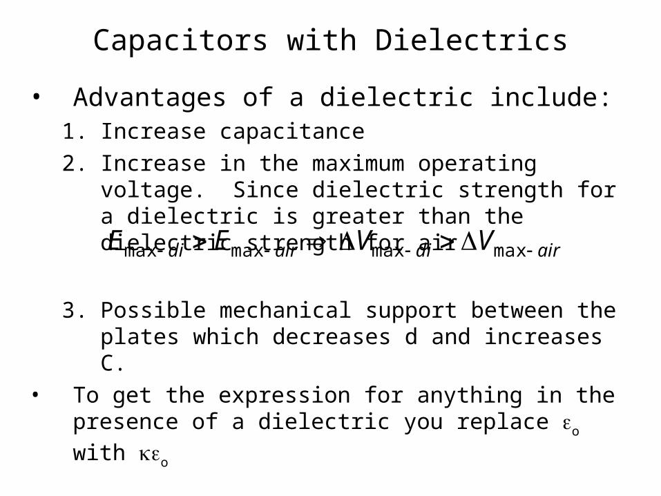
• Advantages of a dielectric include:1. Increase capacitance
2. Increase in the maximum operating voltage. Since dielectric strength for a dielectric is greater than the dielectric strength for air
3. Possible mechanical support between the plates which decreases d and increases C.
• To get the expression for anything in the presence of a dielectric you replace o with o
airdiairdi VVEE maxmaxmaxmax
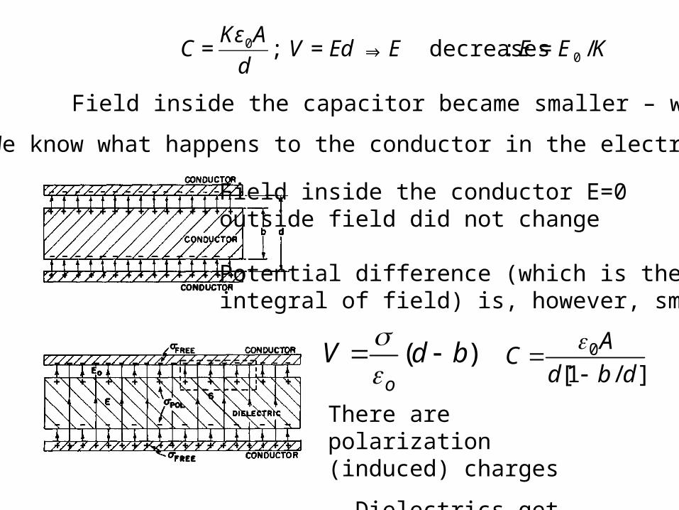
Field inside the capacitor became smaller – why?
There are polarization (induced) charges
– Dielectrics get polarized
We know what happens to the conductor in the electric field
Field inside the conductor E=0outside field did not change
Potential difference (which is the integral of field) is, however, smaller.
( )o
V d b
0
[1 / ]
AC
d b d
€
C =Kε0A
d; V = Ed⇒ E decreases : E = E0 /K
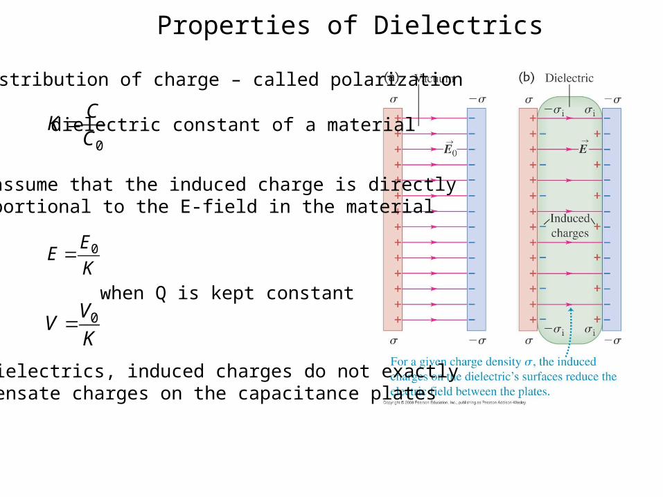
Properties of Dielectrics
0EEK
Redistribution of charge – called polarization
We assume that the induced charge is directly proportional to the E-field in the material
0
CK
C dielectric constant of a material
0VVK
when Q is kept constant
In dielectrics, induced charges do not exactly compensate charges on the capacitance plates
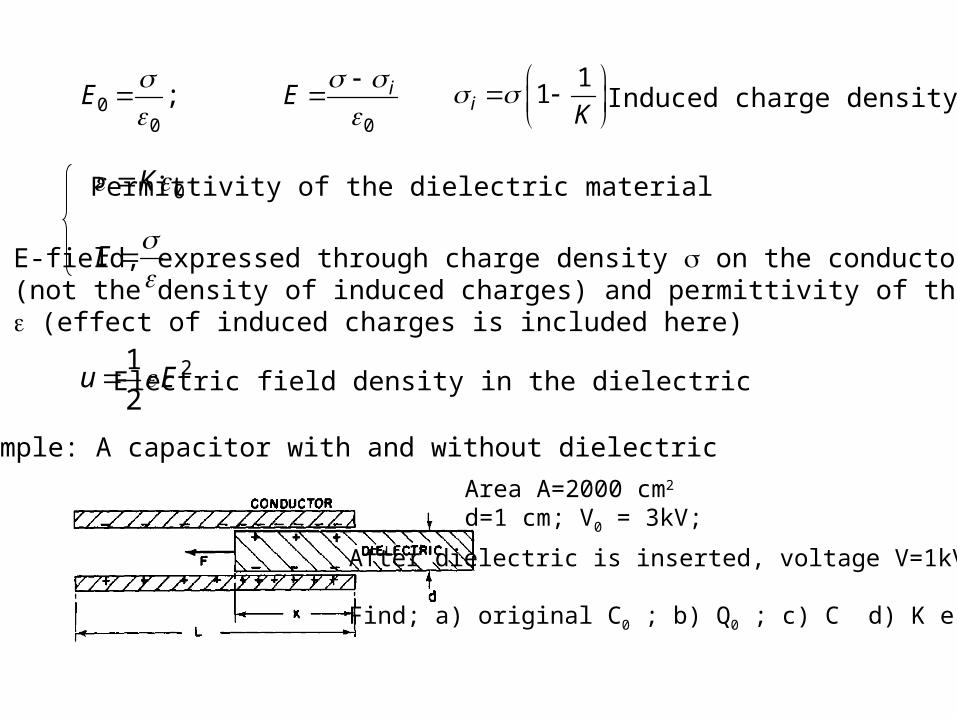
00 0
; iE E
1
1i K
Induced charge density
0K Permittivity of the dielectric material
E
E-field, expressed through charge density on the conductor plates (not the density of induced charges) and permittivity of the dielectric (effect of induced charges is included here)
21
2u E Electric field density in the dielectric
Example: A capacitor with and without dielectric
Area A=2000 cm2
d=1 cm; V0 = 3kV;
After dielectric is inserted, voltage V=1kV
Find; a) original C0 ; b) Q0 ; c) C d) K e) E-field
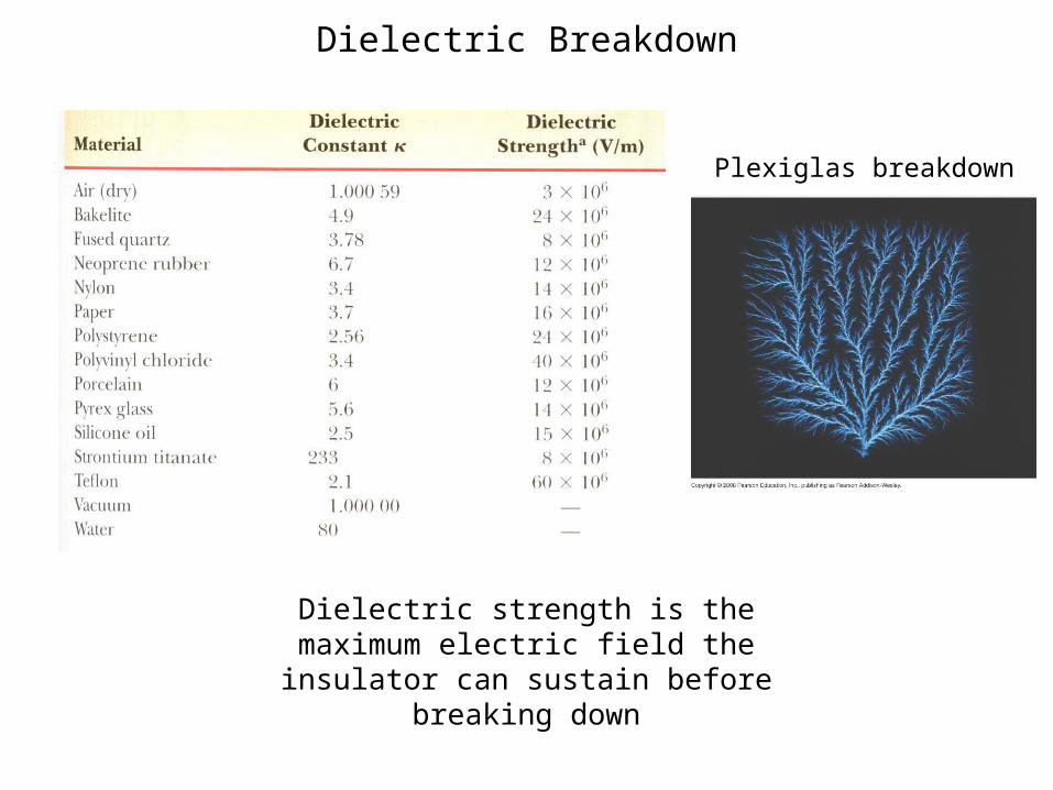
Dielectric Breakdown
Dielectric strength is the maximum electric field the insulator can sustain before breaking down
Plexiglas breakdown
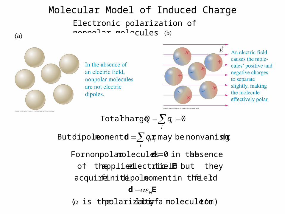
Molecular Model of Induced ChargeElectronic polarization of nonpolar molecules
tom)molecule/a a oflity polarizabi theis (
:field in themoment dipole finite acquire
but they field electric applied theof
absence in the 0 moleculesnonpolar For
ngnonvanishi bemay moment dipoleBut
0 charge Total
0
Ed
E
d
rd
ii
i
ii
q
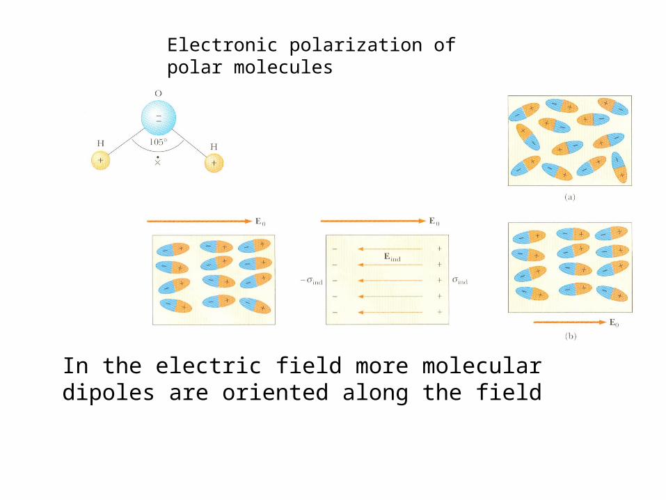
In the electric field more molecular dipoles are oriented along the field
Electronic polarization of polar molecules
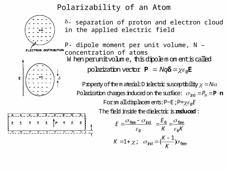
Polarizability of an Atom
- separation of proton and electron cloud in the applied electric field
P- dipole moment per unit volume, N – concentration of atoms
0
When per unit volume, this dipole moment is called
polarization vector Nq P δ E
ind
0
fre
Property of the material: Dielectric susceptibility
Polarization charges induced on the surface:
For small displacements: P~E; P=
The field inside the dielectric is :
n
N
P
E
E
P n
reduced
e ind 0 free
0 0
ind free
11 ; ( )
E
K K
KK
K
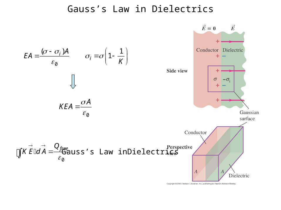
Gauss’s Law in Dielectrics
0
( )i AEA
1
1i K
0
AKEA
0
freeQK E d A
Gauss’s Law inDielectrics
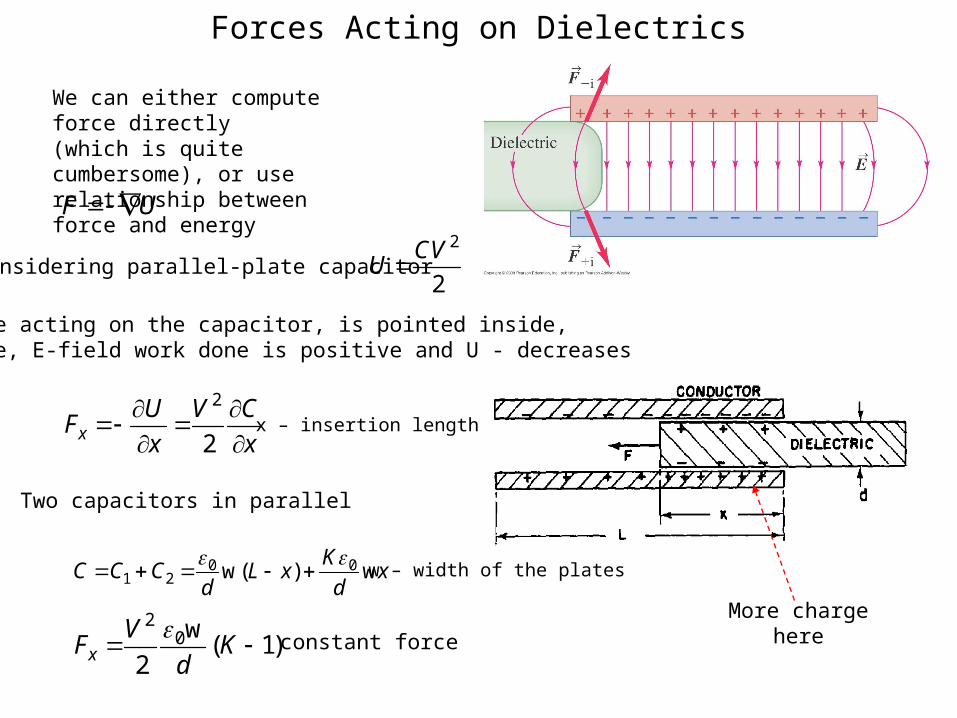
Forces Acting on Dielectrics
More charge here
We can either compute force directly(which is quite cumbersome), or use relationship between force and energy
F U
Considering parallel-plate capacitor 2
2
CVU
Force acting on the capacitor, is pointed inside,hence, E-field work done is positive and U - decreases
2
2xU V C
Fx x
x – insertion length
Two capacitors in parallel
0 01 2 w( ) w
KC C C L x x
d d
w – width of the plates
20w
( 1)2xV
F Kd
constant force