the future for electrocoagulation as a localised water treatment technology · 2016-03-21 · see...
TRANSCRIPT

Seediscussions,stats,andauthorprofilesforthispublicationat:https://www.researchgate.net/publication/7971546
TheFutureforElectrocoagulationasaLocalisedWaterTreatmentTechnology
ARTICLEinCHEMOSPHERE·MAY2005
ImpactFactor:3.34·DOI:10.1016/j.chemosphere.2004.10.023·Source:PubMed
CITATIONS
243
READS
307
3AUTHORS,INCLUDING:
CynthiaAMitchell
UniversityofTechnologySydney
79PUBLICATIONS1,031CITATIONS
SEEPROFILE
Availablefrom:CynthiaAMitchell
Retrievedon:11March2016

Chemosphere 59 (2005) 355–367
www.elsevier.com/locate/chemosphere
The future for electrocoagulation as a localisedwater treatment technology
Peter K. Holt a,*, Geoffrey W. Barton a, Cynthia A. Mitchell b
a Department of Chemical Engineering, University of Sydney, NSW 2006, Sydney, Australiab Institute for Sustainable Futures, University of Technology Sydney, P.O. Box 123, Broadway, NSW 2007, Sydney, Australia
Received 20 April 2004; received in revised form 15 October 2004; accepted 19 October 2004
Abstract
Electrocoagulation is an electrochemical method of treating polluted water whereby sacrificial anodes corrode to
release active coagulant precursors (usually aluminium or iron cations) into solution. Accompanying electrolytic reac-
tions evolve gas (usually as hydrogen bubbles) at the cathode.
Electrocoagulation has a long history as a water treatment technology having been employed to remove a wide range
of pollutants. However electrocoagulation has never become accepted as a �mainstream� water treatment technology.The lack of a systematic approach to electrocoagulation reactor design/operation and the issue of electrode reliability
(particularly passivation of the electrodes over time) have limited its implementation. However recent technical
improvements combined with a growing need for small-scale decentralised water treatment facilities have led to a re-
evaluation of electrocoagulation.
Starting with a review of electrocoagulation reactor design/operation, this article examines and identifies a concep-
tual framework for electrocoagulation that focuses on the interactions between electrochemistry, coagulation and flo-
tation. In addition detailed experimental data are provided from a batch reactor system removing suspended solids
together with a mathematical analysis based on the �white water� model for the dissolved air flotation process. Currentdensity is identified as the key operational parameter influencing which pollutant removal mechanism dominates.
The conclusion is drawn that electrocoagulation has a future as a decentralised water treatment technology. A con-
ceptual framework is presented for future research directed towards a more mechanistic understanding of the process.
� 2004 Elsevier Ltd. All rights reserved.
Keywords: Electrocoagulation; Electrochemistry; Coagulation; Flotation; Water treatment
0045-6535/$ - see front matter � 2004 Elsevier Ltd. All rights reservdoi:10.1016/j.chemosphere.2004.10.023
* Corresponding author. Address: Ecological Engineering,
P.O. Box 453, Prahran, VIC 3181, Australia. Tel.: +61 3 9533
8445; fax: +61 3 9533 7781.
E-mail address: [email protected] (P.K. Holt).
1. Introduction
At the turn of the last century, it was estimated that
some 1.1 billion people (one-sixth of the world�s popula-tion) were without an �improved� water supply (WHO/Unicef, 2000), while in the foreseeable future the de-
mand for water is only expected to grow as human pop-
ulation and industrialization increases (Asmal, 2000).
The right of all people to access suitable water supplies
ed.

Nomenclature
Ab projected bubble area (m2)
F Faraday�s constant (96486C/mol)i current density (Am�2)
I operating current (A)
m mass (g)
M molecular weight (gmol�1)
Nb bubble number concentration (m�3)
Np particle number concentration (m�3)
Npe particle effluent concentration (m�3)
Npi particle influent concentration (m�3)
t run time (s)
tcz contact zone time (s)
vb terminal rise velocity (ms�1)
z number of electrons
apb particle–bubble attachment efficiency
e pollutant removal efficiency
gT single bubble collector efficiency
gD Brownian diffusion collector efficiency
gI interception of the particle by the bubble
collector efficiency
gS sedimentation of the particle onto the bub-
ble collector efficiency
gIN inertial driven contact collector efficiency
356 P.K. Holt et al. / Chemosphere 59 (2005) 355–367
must thus be seen as a global challenge, the solution of
which is dependent on the formulation and implementa-
tion of sustainable water management strategies.
A sustainable water management approach requires
�fit for purpose� use and reuse of water as shown bythe illustrative �water cascade� in Fig. 1. To reverse thisdownward trend water must be treated in some way.
In many developed countries, large-scale centralised
water treatment facilities are both appropriate and
highly cost-effective for this purpose. However even in
such countries, there are numerous situations where
smaller, localised water treatment technologies are pref-
erable to centralised treatment. Indeed the work re-
ported in this paper regarding electrocoagulation was
motivated by an approach from the commercial sector
within Australia for a widely applicable, low-cost batch
water treatment technology.
In essence an electrocoagulation reactor is an electro-
chemical cell wherein a sacrificial metal anode, usually
aluminium but occasionally iron, is used to dose pol-
luted water with a coagulating agent (Vik et al., 1984;
Barkley et al., 1993; Matteson et al., 1995; Pouet and
Grasmick, 1995; Mameri et al., 1998; Holt, 2003). Elec-
Water quality
Potential usefulnes
High
Low
Low
Black water
Grey wa
Irrigation/garden water
Water cascade
Fig. 1. Cascade relationship between wat
trocoagulation introduces metal cations in situ rather
than via external dosing. Simultaneously electrolytic
gases (typically hydrogen) are generated at the cathode.
Depending on the reactor operating conditions and the
pollutant, these bubbles may float some portion of the
coagulated pollutant to the surface.
Electrocoagulation is not a new technology. Indeed
the literature indicates that it has been regularly �discov-ered� over the last hundred years or so, both in batchand continuous applications. For example, during the
late 19th century several large-scale water treatment
plants were commissioned in London (Matteson et al.,
1995), while electrolytic sludge treatment plants were
operating as early as 1911 in various parts of the USA
(Vik et al., 1984) with similar plants being commissioned
to treat municipal wastewater in the following decades.
By the 1930s however, all such plants had been aban-
doned due to higher operating costs and the ready avail-
ability of mass-produced alternatives for chemical
coagulant dosing. In more recent times, there has been
some renewed interest in continuously fed water treat-
ment plants based on electrocoagulation technology
(some with sizeable throughputs) for specialised indus-
s
Potable
High
ter
Rainwater
Water treatment (increases quality)
Water use (decreases quality)
KEY
er quality and potential usefulness.

P.K. Holt et al. / Chemosphere 59 (2005) 355–367 357
trial applications, such as the removal of fine material
from coal wash water. However because of its proven
ability to effectively remove an extremely wide range of
pollutants, together with its inherent simplicity of design
and operation, electrocoagulation is being re-examined
as a localised low-cost treatment technology.
In reviewing the future status of electrocoagulation, a
number of major deficiencies were identified. The first is
that the literature does not reveal any systematic ap-
proach to electrocoagulation reactor design and opera-
tion. Reported designs range through laboratory, pilot
and industrial scales, both as stand-alone reactors
through to fully integrated units within a wastewater
purification system. Certainly there is no dominant reac-
tor design in use today, while very little is available in
the way of comparative reactor performance. This arti-
cle thus begins (in Section 2) by reviewing the literature
on electrocoagulation, seeking to introduce a structured
approach to highlight commonalities and differences be-
tween the work reported. The second deficiency is the al-
most complete lack of published data on the operation
of batch electrocoagulation reactors, seen as the most
likely means of providing a localised water treatment
facility. Section 3 thus contains detailed experimental re-
sults from a laboratory scale batch reactor, while the fol-
lowing section outlines a simple modelling approach
that is consistent with the observed data. The third defi-
ciency is intimately linked with the previous two, in that
little guidance is available for a priori reactor design or
performance prediction. Thus in Section 5 a framework
is proposed as an aid to further understanding of the
myriad interactions that can occur between the funda-
mental processes (i.e. electrochemistry, coagulation,
sedimentation and flotation) taking place within an elec-
trocoagulation reactor.
The final deficiency (not specifically considered in this
paper) relates to the fact that an electrocoagulation reac-
tor is an electrochemical cell and thus its performance is
directly related to the operational state of its electrodes.
These vary widely in material used, design and mode of
operation from simple vertical plate arrangements to
packed-bed style reactors containing various metallic
packings (Ogutveren et al., 1992; Barkley et al., 1993).
Electrode passivation, specifically of aluminium elec-
trodes, has been widely observed and recognised as det-
rimental to reactor performance (Osipenko and
Pogorelyi, 1977; Novikova et al., 1982). This formation
of an inhibiting layer, usually an oxide, on the electrode
surface prevents metal dissolution and electron transfer,
thereby limiting coagulant addition to the solution. Over
time, the thickness of this layer increases, reducing the
efficacy of the electrocoagulation process as a whole.
The use of new materials, different electrode types and
arrangements (Pretorius et al., 1991; Mameri et al.,
1998) and more sophisticated reactor operational strate-
gies (such as periodic polarity reversal of the electrodes)
have certainly led to significant reductions in the impact
of passivation, although it must be admitted that this
issue is still seen as a serious potential limitation for
applications where a low-cost, low maintenance water
treatment facility is required.
2. Electrocoagulation reactor design and operation
Given the time-scale over which this technology has
been utilized, it is somewhat surprising that the available
literature does not reveal any systematic approach to
electrocoagulation reactor design and operation. The
reason for this failure to drive towards some agreed
�best� solution would seem to be the lack of any quanti-tative understanding of the many interactions that occur
within an electrocoagulation reactor, and in particular
the ability to predict the relative importance of these
interactions for a given situation. The key driver for
the development of any particular application of this
technology has generally been the removal of a specific
pollutant. Such �pollutant centred� studies have charac-terised almost all the published research into electroco-
agulation. Consequently, despite more than a century�sworth of applications, many of them deemed successful,
the science and engineering behind electrocoagulation
reactor design is still largely empirical and heuristic.
These studies invariably prove the viability of the tech-
nology, but singularly fail to capitalise on its potential
by being incorporated within a broad-based understand-
ing of electrocoagulation technology.
Published electrocoagulation reactor designs may be
classified as shown in Fig. 2. The first major distinction
between alternative designs is whether a reactor was
configured as a batch or a continuous system. It is clear
that the majority of applications fall into the latter cat-
egory, having a continuous feed of wastewater and oper-
ating under (pseudo) steady-state conditions. A key
advantage for such reactor systems is that their coagu-
lant requirements are essentially fixed, a major advan-
tage in terms of both design and operation. Batch
reactor applications on the other hand typically operate
with a fixed wastewater volume per treatment cycle but
suffer from the perceived disadvantage (from a design
and operational standpoint) that conditions within the
reactor change with time. This dynamic behaviour is
clearly illustrated in Section 3 where experimental data
are given for the removal of suspended solids (i.e. clay)
from a synthetic wastewater. Here the time dependent
behaviour results from the fact that the coagulant pre-
cursor (i.e. aluminium cations) is continuously �fed� tothe reactor as the anode corrodes. The aluminium ca-
tions are hydrolysed to a form capable of aggregating
the pollutant which is then removed from solution by
sedimentation and/or flotation. As a result, both pollu-
tant and coagulant levels shift over time as material is

Batch Continuous
SettlerMatteson et al. (1995)
In situHolt et al. (2001)
CentrifugeDo and Chen(1994)
SettlerMameri et al. (1998)
SettlerBarkley et al. (1993)Donini et al. (1994)Groterud and Smoczynski (1986)Matteson et al.(1995)Pretorius et al. (1991)
Electro-flotationGott (1977)Weintraub et al.(1983)
ClarifierCerisier and Smit(1996)Woytowich et al(1993)
DAF (DissolvedAir Flotation)Pouet and Grasmick (1995)
SettlerOsipenko andPogorelyi (1977)Sanfran (1991)Mameri et al. (1998)
FiltrationBalmer and Foulds(1986)Nikolaev et al.(1982)Sanfran (1991)
FlotationWeintraub et al(1983)
CentrifugeNikolaev et al (1982)
In situChen et al. (2000)Vik et al. (1984)
Coagulation only
Coagulation and Flotation
Electrocoagulation reactors
Coagulation only
Coagulation and Flotation
FiltrationGroterud and Smoczynski (1986)Zabolotsky et al.(1996)
HydrocycloneKoren andSyversen (1995)
Batch Continuous
SettlerMatteson et al. (1995)
In situHolt et al. (2001)
CentrifugeDo and Chen(1994)
SettlerMameri et al. (1998)
SettlerBarkley et al. (1993)Donini et al. (1994)Groterud and Smoczynski (1986)Matteson et al.(1995)Pretorius et al. (1991)
Electro-flotationGott (1977)Weintraub et al.(1983)
ClarifierCerisier and Smit(1996)Woytowich et al.(1993)
DAF (DissolvedAir Flotation)Pouet and Grasmick (1995)
SettlerOsipenko andPogorelyi (1977)Sanfran (1991)Mameri et al. (1998)
FiltrationBalmer and Foulds(1986)Nikolaev et al.(1982)Sanfran (1991)
FlotationWeintraub et al.(1983)
CentrifugeNikolaev et al. (1982)
In situChen et al. (2000)Vik et al. (1984)
Coagulation only
Coagulation and Flotation
Electrocoagulation reactors
Coagulation only
Coagulation and Flotation
FiltrationGroterud and Smoczynski (1986)Zabolotsky et al.(1996)
HydrocycloneKoren andSyversen (1995)
Fig. 2. Classification of electrocoagulation reactor systems. See above-mentioned references for further information.
358 P.K. Holt et al. / Chemosphere 59 (2005) 355–367
added to the solution, is modified within the solution,
and is removed from solution.
The second major distinction between alternative
reactor designs is the role of flotation. Reactors that
do not exploit the separation of aggregated pollutant
via electrochemically generated bubbles are labelled in
Fig. 2 as �coagulation only� processes, while reactors thatintegrate flotation into their design and operation are
classed as �coagulation and flotation� processes. If noadditional separation process is required (i.e. separation
occurs within the electrocoagulation reactor itself), rele-
vant references are cited directly below (being connected
by a vertical arrow and a dashed box). Otherwise, the
additional separation processes are reported in bold with
relevant references grouped accordingly. Integrated
units have two main pollutant removal paths—flotation
and settling (Holt et al., 2001). Separation by settling is
the more common option, with the fact that electrolytic
gases are also being produced simultaneously with the
dosing process often viewed as an unnecessary opera-
tional complication (Mameri et al., 1998). The prime dif-
ferentiator between pollutant removal by settling or
flotation would seem to be the current density employed
in the reactor. A low current produces a low bubble den-
sity, leading to a low upward momentum flux—condi-
tions that encourage sedimentation over flotation (Holt
et al., 2002). As the current is increased, so the bubble
density increases resulting in a greater upwards momen-
tum flux and thus more likely removal by flotation.
�Coagulation only� processes can be further differenti-ated on the basis of the type of aggregated pollutant sep-
aration technology used. As shown, electrocoagulation
dosing has been combined with most common separation
technologies including dissolved air flotation, electroflo-
tation, filtration and clarification. Basically, pollutant
separation is either integrated into the reactor�s design,or else occurs in a separate (downstream) unit.
The value of the hierarchic structure shown in Fig. 2
is that it succinctly summarises previous electrocoagula-
tion reactor design practice and demonstrates that it is
possible to reduce a myriad applications to combina-
tions of just three core design decisions.
• Batch or continuous operation.• The role played by electrolytically generated bubbles.• The means of separating out the aggregatedpollutant.
For example, the applications shown in Table 1 (for
removing suspended solids) may be readily differentiated
from each other on the basis of these design decisions.
Similar tabulations (Holt, 2003) related to the removal
of heavy metals and ionic species, colour dyes and organ-
ic material (including fats, oils and greases) confirm the
value of classifying diverse applications on this simple
basis. Consequently the design of any future localised
water treatment facility built around electrocoagulation
technology may be simplified by making initial reactor

Table 1
Summary of electrode properties for suspended solids removed by electrocoagulation
Reference Pollutant Electrical
requirementaElectrodesb Electrode
type
Pollutant
removal
Reactor type
Abuzaid et al. (1998) Bentonite 0.2–1A A = SS C = SS Plates Settling (implied) Batch (4 l)
Avetisyan et al. (1984) Carbon 120–170Am�2 A = Al C = Fe Plates Flotation Continuous
Belongia et al. (1999) Silica, alumina 2.5–10.0Vcm�1 A = SS C = SS Mesh Settling Batch (3 l)
Holt et al. (2001) Clay 3.4–27Am�2 A = Al C = SS Plates Flotation and settling Batch (7 l)
Ivanishvili et al. (1987) Suspended solids 5–50Am�2 A = Al C = Fe Plates Settling Continuous
Matteson et al. (1995) Kaolinite 0.01Am�2 A = SS C = SS Mesh Settling Stirred batch
(and series of
batch reactors)
Syrbu et al. (1986) Suspended solids 50–70Am�2 A = Al C = SS Plates Flotation
(inseparate chamber)
Continuous
a Reactor electrical requirements are reported with appropriate units indicated.b A and C refer to anode and cathode, respectively and SS refers to stainless steel.
P.K. Holt et al. / Chemosphere 59 (2005) 355–367 359
design and operation considerations as combinations of
these three design decisions.
3. Operation of a batch electrocoagulation system
Based on the previous review of reactor design and
operation, it seems clear that the simplest option for a
low-cost localised water treatment facility involves a
batch reactor system with vertical plate electrodes where
separation of the aggregated pollutant is integral to the
reactor design with use being made of electrolytic gas
flotation. The fact that surprisingly few such cases have
been reported in the literature (see Table 1) may be
attributed to the supposed �complexity� introduced bythe time dependent nature of such systems and, as noted,
the almost complete lack of dynamic experimental data
Fig. 3. Batch electrocoagul
from such systems. This section reports on the experi-
mental setup and data from one such reactor system.
The reactor system used (see Fig. 3) was constructed
of Perspex and had a maximum capacity of 7.1 l. The
�pollutant� used was a potter�s clay. Details of the sizedistribution and material composition of this material
have been reported elsewhere (Holt et al., 2002). Five
stainless steel cathodes were interspersed with four alu-
minium anodes, with brass rods used to connect the par-
allel plate electrodes. The electrodes have an active
surface area of 732cm2 with a surface area to volume
ratio of 10.5m2m�3 which falls within the range re-
ported in the literature.
Electrical conductivity, total dissolved solids, salinity
and temperature were all measured using a WTW LF340
probe, while pH was measured in a flow-through
cell drawing solution from the reactor at a rate of
ation reactor system.

360 P.K. Holt et al. / Chemosphere 59 (2005) 355–367
0.30 lmin�1 using a peristaltic pump. The current flow-
ing through the cell and the voltage across the electrodes
were both recorded using a data logger. The current was
held constant for each run, being varied over the range
0.25–2.0A (i.e. equivalent to a current density of 3.4–
27Am�2). Aluminium concentration was measured
using a varian atomic absorption spectrophotometer,
while turbidity and zeta potential were measured off-line
using a Merck Turbiquant 1500T (tungsten lamp) and
Malvern Zetasizer, respectively.
All runs were conducted with an initial clay load-
ing in the range 0.1–1.6g l�1 using 6 l of de-ionised
water. Sodium chloride was added to adjust solution
conductivity and allow the requisite current to pass
through the reactor. Initial results indicated that
above 350lScm�1 (equivalent to a concentration of
0.15g l�1) there was no change in the system�s response.Consequently to remove the influence of conductivity a
�standard� concentration of 0.20g l�1 sodium chloridewas used for all subsequent electrocoagulation experi-
ments. It should be noted that this level of 200mgl�1
is less than the ionic concentration of �fresh� water (at-most about 1000mgl�1) and substantially less than the
concentration of sea-water (some 35000mgl�1).
Fig. 4 is a typical plot showing the dynamic nature of
this batch reactor system. Note that turbidity has been
normalised (against its initial value) to aid comparisons
between runs. Three stages can clearly be identified—
namely, a lag, a reactive and a stabilising stage. Little
or no turbidity change is observed in the lag stage with
the majority (�95%) of the turbidity removal occurringduring the reactive stage. As time progresses, the rate of
turbidity reduction decreases and the turbidity levels out
during the stabilising stage. The solution pH was moni-
tored rather than controlled and stabilised to about 8.5
after 10min operation.
8.0
8.5
9.0
9.5
10.0
10.5
11.0
0 10 20 30Time (m
pH
Lag stage
pH profile
Reactive stage
Turbidity profile
Fig. 4. Dynamic response of batch reactor; [clay] = 0.
3.1. Impact of pollutant loading
Fig. 5(a) presents normalised turbidity results for
pollutant loadings over the range 0.1–1.6g l�1 at a con-
stant current density of 14Am�2. Note that as a repro-
ducibility check one set of conditions was repeated a
number of time (n = 4), with the averaged response
being shown here. The response for all pollutant load-
ings was similar with some difference observed in the
residual normalised turbidity levels. However, when
compared on an absolute turbidity basis, 1.6g l�1 and
0.1g l�1 pollutant loading levels gave almost identical
residual values of 4.3 and 3.6 NTU, respectively. Thus,
for this system at least, the extent of turbidity removal
was essentially independent of the initial pollutant
load—a result that hinted strongly at a dominant re-
moval mechanism that was independent of pollutant
loading.
Dynamic mass balance results were also conducted
on the runs shown in Fig. 5(a) and are reported here
in two ways. Firstly the cumulative mass removed at
the surface of the reactor (i.e. transported by the hydro-
gen bubbles generated at the cathodes) is presented in
Fig. 5(b) as a function of time and initial pollutant load-
ing. Alternatively the mass balance data over a 1h
period are presented in Table 2. It should be noted that
the mass added to the reactor was a combination of ini-
tial pollutant (i.e. clay) loading and coagulant addition,
with 1h operation at 14Am�2 generating a calculated
0.97g of aluminium hydroxide. Thus at the lowest pollu-
tant loading (0.1g l�1), a greater proportion of the final
total mass in the system was actually the result of coag-
ulant generation (53%) than was initially present as pol-
lutant. Subsequent runs to investigate the impact of the
operating current on the dominant removal mechanism
(i.e. settling or flotation) were carried out at a pollutant
40 50 60in)
0
10
20
30
40
50
60
70
80
90
100
Nor
mal
ised
Tur
bidi
ty (%
)Stabilising stage
8g/l; initial turbidity = 631 NTU; i = 6.8Am�2.

0
10
20
30
40
50
60
70
80
Cum
ulat
ive
mas
s re
mov
ed a
t sur
face
(%
of t
otal
mas
s)
[clay] = 0.1 g l-1 (n=1)[clay] = 0.4 g l-1 (n=1)[clay] = 0.8 g l-1 (n=4)[clay] = 1.6 g l-1 (n=1)
0.1
1
10
100
Nor
mal
ised
Tur
bidi
ty (%
)
error bars ± σ
0
10
20
30
40
50
60
70
0 10 20 30 40 50 60
Time (min)
Cum
ulat
ive
mas
s co
llect
ed a
t sur
face
(%
of t
otal
mas
s)
3.4 A m-2
14 A m-2
27 A m-2
[clay] = 0.1 g l-1 (n=1); 83 NTU[clay] = 0.4 g l-1 (n=1); 280 NTU[clay] = 0.8 g l-1 (n=4); 549 NTU[clay] = 1.6 g l-1 (n=1); 1092 NTU
(a)
(b)
(c)
Fig. 5. (a) Normalised turbidity as a function of time and pollutant loading; i = 14Am�2. (b) Cumulative mass collected at the surface
as a function of time and pollutant loading; i = 14Am�2. (c) Cumulative mass collected at the surface as a function of time and current
density; [clay] = 0.8g/l.
P.K. Holt et al. / Chemosphere 59 (2005) 355–367 361
loading of 0.8g l�1, thus limiting this potential source of
experimental inaccuracy. Experimental details of the
mass balancing procedures are given elsewhere (Holt,
2003).
In terms of evaluating batch electrocoagulation as a
candidate technology for providing low-cost, low main-
tenance localised water treatment, these preliminary
experiments clearly demonstrated that the performance
of such a system can be quite robust (i.e. insensitive to
large operational changes) with respect to both solution
conductivity and pollutant loading.
3.2. Operating current density
Operating current density is critical in batch electro-
coagulation, as it is the only operational parameter that

Table 2
Mass balance breakdown over an hour of operation; [clay] = 0.1–1.6g/l; i = 14Am�2
Loading (g/l) Mass in (t = 0min) Mass out (t = 60min)
Total,
g
Total clay,
g (% total)
Total Al(OH)3,
g (% total)
At surface,
g (% total)
At base,
g (% total)
In bulk solution,
g (% total)
1.6 12.00 11.03 (92%) 0.97 (8%) 6.12 (51%) 5.62 (47%) 0.26 (2%)
0.8 6.49 5.52 (85%) 0.97 (15%) 3.59 (55%) 2.63 (41%) 0.27 (4%)
0.4 3.76 2.79 (74%) 0.97 (26%) 2.42 (64%) 1.20 (32%) 0.14 (4%)
0.1 1.82 0.85 (47%) 0.97 (53%) 1.33 (73%) 0.50 (27%) 0.0 (0%)
0
10
20
30
40
50
60
70
0 10 20 30 40
Total Al dosage (mg/l)
Cum
ulat
ive
mas
s re
mov
ed a
tsur
face
(%
of t
otal
mas
s)
2 Amp (n = 1)1 Amp (n = 4)0.25 Amp (n = 1)
14 A m-2
3.4 A m-2
27 A m-2
27 A m-2 (n=1)14 A m-2 (n=4)3.4 A m-2 (n=1)
Fig. 6. Cumulative mass collected at the surface as a function
of coagulant addition and operating current; [clay] = 0.8g/l.
362 P.K. Holt et al. / Chemosphere 59 (2005) 355–367
can be controlled directly. In this system electrode spac-
ing is fixed and current is a continuous supply. Current
density directly determines both coagulant dosage and
bubble generation rates, as well as strongly influencing
both solution mixing and mass transfer at the electrodes.
Thus a set of experiments were carried out to quantify
the impact of operating current on reactor performance.
This was done on two related bases—a dynamic (or time
dependent) basis and an equivalent aluminium concen-
tration basis. Fig. 5(c) and Table 3 present results in
an analogous fashion to that employed above for pollu-
tant loading. Both presentations show clear differences
between the three current density levels used.
The mass balance data show that at the lowest cur-
rent density (3.4Am�2), only 26% of the total mass
input to the system had been transported to the surface
by flotation after 4h operation, with some 73% of the
total mass reporting to the base of the reactor. Settling
of the aggregated pollutant was clearly the dominant re-
moval mechanism at this low current density where few-
er bubbles were produced at the cathode, resulting in a
decrease in solution mixing and material uplift. Con-
versely, at the highest current density (27Am�2), 63%
of the total mass had reported to the surface after just
1h. Flotation was clearly favoured here by the higher
bubble density and coagulant dosage rate occurring at
this current density.
Faraday�s law may be used to relate the mass (m) ofelectrolytically generated aluminium going into solution
to the operating current (I) and the run time (t). In this
relationship, M is the atomic weight of aluminium, z is
the number of electrons transferred in the anodic disso-
lution (here z = 3), while F is Faraday�s constant(96486Cmol�1).
Table 3
Mass balance breakdown as a function of current density; [clay] = 0.8
Mass in
Current density,
Am�2Time,
min
Total,
g
Total clay,
g (% total)
Total Al(
g (% tota
3.4 240 6.49 5.52 (85%) 0.97 (15%
14 60 6.49 5.52 (85%) 0.97 (15%
27 60 7.48 5.54 (74%) 1.94 (53%
m ¼ ItMzF
Using this equation, the amount of coagulant delivered
to the solution may be calculated. Thus Fig. 6 shows
the system�s response not on a simple time basis but asa function of the total amount of coagulant put into
solution—the latter being quoted as an equivalent alu-
minium concentration. When plotted in this way, the re-
sults were somewhat counter-intuitive. As expected, the
lowest current density (3.4Am�2) removed the least
mass to the surface as aluminium concentration in-
creased, primarily due to the dominance of settling.
Operation at 27Am�2 (which had the highest coagulant
and hydrogen bubble generation rates) might be ex-
g/l
Mass out
OH)3,
l)
At surface,
g (% total)
At base,
g (% total)
In bulk solution,
g (% total)
) 1.68 (26%) 4.76 (73%) 0.05 (1%)
) 3.59 (55%) 2.63 (41%) 0.27 (4%)
) 4.70 (63%) 2.93 (39%) �0.15 (�2%)
P.K. Holt et al. / Chemosphere 59 (2005) 355–367 363
pected to achieve the greatest mass removal to the sur-
face. Yet on an aluminium basis, it was the mid-range
current density case (14Am�2) that resulted in the great-
est mass reporting to the surface. In other words, a cur-
rent density of 14Am�2 resulted in the most efficient
usage of the available coagulant, if efficiency is defined
as the pollutant mass removed to the surface per unit
of coagulant provided.
In terms of evaluating batch electrocoagulation as
a candidate technology for providing low-cost, low
maintenance localised water treatment, this set of exper-
iments clearly demonstrated two important results.
Firstly, that operating current density is the key opera-
tional parameter, affecting not only the system�s re-sponse time but also strongly influencing the dominant
pollutant separation mode. Secondly however, these re-
sults would also seem to indicate that running the reac-
tor at the highest allowable current density may not be
the most efficient mode of operation. For any specific
application, the �optimal� current density will invariablyinvolve a trade-off between operational costs and effi-
cient use of the introduced coagulant.
1.E-04
1.E-03
1.E-02
1.E-01
1.E+00
0.001 0.01 0.1 1 10 100
Particle diameter (µm)
, sin
gle
colle
ctor
col
lisio
n ef
ficie
ncy
ηD
ηI
ηS
ηIN
T
η
η
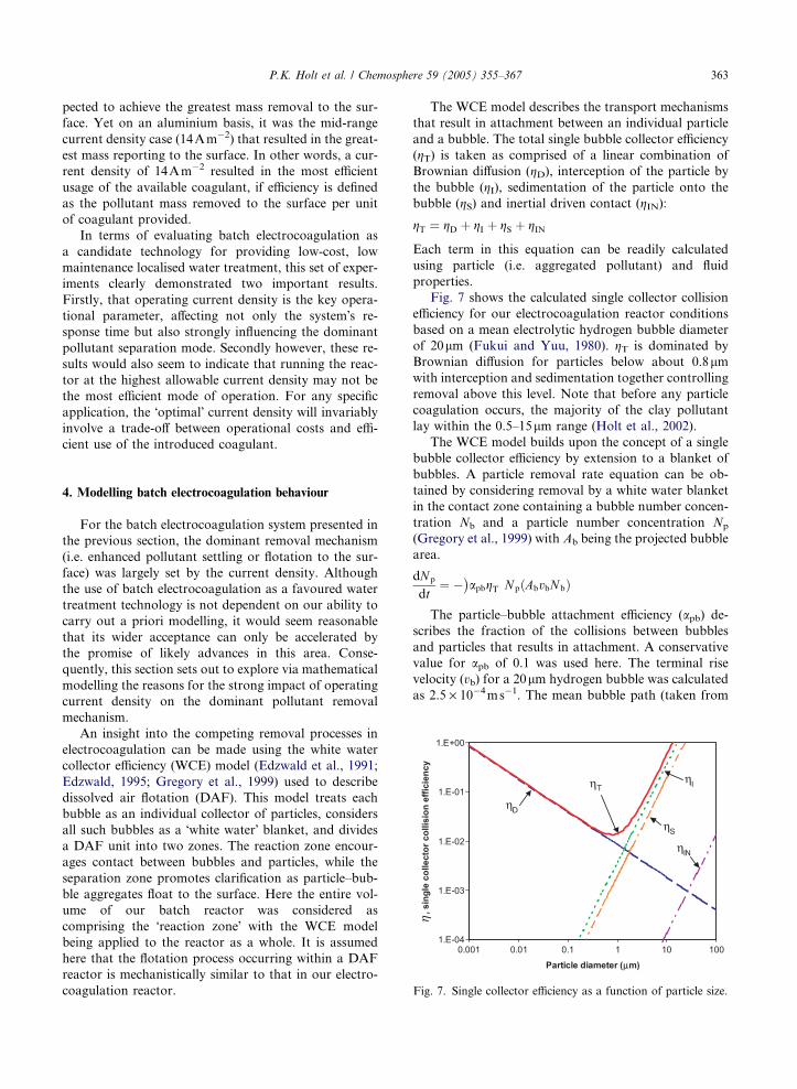
Fig. 7. Single collector efficiency as a function of particle size.
4. Modelling batch electrocoagulation behaviour
For the batch electrocoagulation system presented in
the previous section, the dominant removal mechanism
(i.e. enhanced pollutant settling or flotation to the sur-
face) was largely set by the current density. Although
the use of batch electrocoagulation as a favoured water
treatment technology is not dependent on our ability to
carry out a priori modelling, it would seem reasonable
that its wider acceptance can only be accelerated by
the promise of likely advances in this area. Conse-
quently, this section sets out to explore via mathematical
modelling the reasons for the strong impact of operating
current density on the dominant pollutant removal
mechanism.
An insight into the competing removal processes in
electrocoagulation can be made using the white water
collector efficiency (WCE) model (Edzwald et al., 1991;
Edzwald, 1995; Gregory et al., 1999) used to describe
dissolved air flotation (DAF). This model treats each
bubble as an individual collector of particles, considers
all such bubbles as a �white water� blanket, and dividesa DAF unit into two zones. The reaction zone encour-
ages contact between bubbles and particles, while the
separation zone promotes clarification as particle–bub-
ble aggregates float to the surface. Here the entire vol-
ume of our batch reactor was considered as
comprising the �reaction zone� with the WCE modelbeing applied to the reactor as a whole. It is assumed
here that the flotation process occurring within a DAF
reactor is mechanistically similar to that in our electro-
coagulation reactor.
The WCE model describes the transport mechanisms
that result in attachment between an individual particle
and a bubble. The total single bubble collector efficiency
(gT) is taken as comprised of a linear combination ofBrownian diffusion (gD), interception of the particle bythe bubble (gI), sedimentation of the particle onto thebubble (gS) and inertial driven contact (gIN):
gT ¼ gD þ gI þ gS þ gIN
Each term in this equation can be readily calculated
using particle (i.e. aggregated pollutant) and fluid
properties.
Fig. 7 shows the calculated single collector collision
efficiency for our electrocoagulation reactor conditions
based on a mean electrolytic hydrogen bubble diameter
of 20lm (Fukui and Yuu, 1980). gT is dominated byBrownian diffusion for particles below about 0.8lmwith interception and sedimentation together controlling
removal above this level. Note that before any particle
coagulation occurs, the majority of the clay pollutant
lay within the 0.5–15lm range (Holt et al., 2002).The WCE model builds upon the concept of a single
bubble collector efficiency by extension to a blanket of
bubbles. A particle removal rate equation can be ob-
tained by considering removal by a white water blanket
in the contact zone containing a bubble number concen-
tration Nb and a particle number concentration Np(Gregory et al., 1999) with Ab being the projected bubble
area.
dNpdt
¼ � apbgT� �
Np AbvbNbð Þ
The particle–bubble attachment efficiency (apb) de-scribes the fraction of the collisions between bubbles
and particles that results in attachment. A conservative
value for apb of 0.1 was used here. The terminal risevelocity (vb) for a 20lm hydrogen bubble was calculatedas 2.5 · 10�4ms�1. The mean bubble path (taken from

364 P.K. Holt et al. / Chemosphere 59 (2005) 355–367
the middle of an electrode to the surface) was 130mm
and hence the average rise time was 8.9min for an
unhindered bubble. The mean bubble rise time was
equated to the contact zone time (tcz) in the WCE model.
The bubble number concentration (Nb) can be esti-
mated using the mean rise time, the hydrogen mass gen-
eration rate (noting that the generation rate is directly
proportional to current according to Faraday�s Law)and the bubble diameter. For an operating current den-
sity of 14Am�2 and 20lm bubbles, Nb was estimated tobe 2.5 · 1012m�3.
Upon integration of the particle removal rate equa-
tion, an expression can be derived relating the particle
effluent concentration (Npe) to the particle influent con-
centration (Npi). Note that the �effluent� should bethought of as what leaves the WCE reaction zone, after
particles have been removed by bubble attachment and
flotation to the reactor surface.
NpeNpi
¼ exp �apbgTtczAbvbNb� �
This expression can be used to predict pollutant removal
efficiency (e) by flotation assuming the electrocoagula-tion reactor acts as a white water collector, as shown
in Fig. 8. Bubble attachment calculations (similar to
those presented by Edzwald, 1995) showed that the
number of bubbles attached per floc and the estimated
density of the aggregate did not strongly influence the
overall floc removal rate by flotation. Rather these cal-
culations showed that the most likely source of error
in these estimates was associated with the probability
of particle–bubble attachment (apb).Fig. 8 relates the effective flotation removal efficiency
(e) to the aggregate size. Coagulant addition results inaggregation with an increase in �particle� size to within
0.0
0.1
0.2
0.3
0.4
0.5
0.6
0.7
0.8
0.9
1.0
0.01 0.1 1 10 100'Particle' diameter (dp) (µm)
ε=
1 - N
pe/N
pi
27 A m-2
14 A m-2
3.4 A m-2
Sedimentation
Flotation
Fig. 8. Removal efficiency (by flotation) as a function of
particle diameter and operating current density.
the range 5–20lm where the bulk of the pollutant isreadily removed by flotation. Operation of the electroco-
agulation reactor at higher current densities (27Am�2)
also increases the bubble number concentration (Nb).
This combination of increased aggregation and an in-
creased bubble number concentration is the reason for
the dominance of flotation as the removal mechanism
at high currents in this reactor. The reactor is operating
in the �coagulation and flotation� mode identified earlier(see Fig. 2). At low current density (3.4Am�2), aggrega-
tion still occurs (but on a longer time scale) but the bub-
ble number concentration is insufficient to ensure high
flotation rates, hence making sedimentation the domi-
nant removal mechanism. This reduction in flotation
effectiveness for low current density is clearly seen in
Fig. 8. Under these conditions, the electrocoagulation
reactor is primarily operating as an electrochemical dos-
ing device (i.e. in the �coagulation only� mode shown inFig. 2).
5. A framework for future research of
electrocoagulation
Electrocoagulation is an enigmatic technology. De-
spite having been widely used for over a century, there
appears to be no real consensus on the most appropriate
approach for any given application, little in the way of
systematic reactor design rules, and almost nothing in
the way of a generic a priori modelling approach. The
root cause of this situation seems to be that electrocoag-
ulation is a technology that lies at the intersection of
three more fundamental technologies—electrochemistry,
coagulation and flotation. Each of these is well-studied
in its own right. However, it is clear from the published
literature that what is lacking is a quantitative apprecia-
tion of the way in which these technologies interact to
provide an electrocoagulation system. For electrocoagu-
lation to play a wider role as an accepted and depend-
able water treatment technology, research is required
that focuses neither on simply making a specific (pollu-
tant-centred) application work nor on any one of the
foundation technologies, but rather the emphasis needs
to be on explaining and quantifying the key interactions
between electrochemistry, coagulation and flotation.
One possible conceptual framework is shown in Fig.
9. Each foundation area brings a certain perspective to
electrocoagulation, as represented by each lobe of this
Venn diagram. The aim here is to show how electrocoag-
ulation�s complexity can be simplified using a reduction-ist approach. Relevant phenomena, characterisation
methods and tools are highlighted in each lobe. Infor-
mation presented in the intersection between two lobes
represents knowledge that links the foundation areas.
For example, thermodynamic modelling of the solution
chemistry of hydrolysed metal cations links the electro-

COAGULATIONFLOTATION
ELECTROCHEMISTRY
Coagulant produced Thermodynamic model
Solution Chemistry pH, speciation
Hydrolyzed metal salts
ParticleCharacterisation Particle size distributionZeta Potential Fractal dimension
Flotation rates Buoyancy
Settling ratesGravity
Kinetics (Tafel) PowerPassivation
Electrolytic gasesproduced Gas type Agitation Mixing due to bubbles Contact patterns
Kinetics
Bubble CharacterisationBubble size distributionBubble density
Operating parameterse.g. current density
BubbleDensity
Coagulant Dosage
Half-cell reactions Electrode material &arrangement
Electrochemical Characterisation
Fig. 9. Conceptual framework for electrocoagulation as a �synthesis� technology.
P.K. Holt et al. / Chemosphere 59 (2005) 355–367 365
chemistry and coagulation lobes. Central to understand-
ing and describing electrocoagulation as a whole are the
contact pattern (i.e. mixing) and process kinetics. The
first of these describes how the various species (coagu-
lant, pollutant particles, bubbles) move and are brought
into proximity with each other, while the latter describes
the rate at which interactions between the various spe-
cies occurs. Hence, these aspects are placed at the inter-
section of all three lobes.
As shown in Sections 3 and 4, it is a combination of
physico-chemical processes occurring within an electro-
coagulation reactor that shifts the dominant pollutant
separation mechanism between (gravity driven) settling
and (buoyancy driven) flotation. The vertical arrows in
Fig. 9 represent these two removal paths with the rela-
tive importance of each being set by a combination of
reactor design and operating parameters. As an exam-
ple, current density (represented by a double-headed
arrow at the base of Fig. 9) shifts the relative importance
between the flotation and coagulation lobes, as it deter-
mines both the coagulant dosage and bubble production
rates, as well as influencing the extent of mixing within a
reactor. The message here is that decisions about reactor
design cannot be made in isolation, as there is an insep-
arable link between design and operational parameters
brought about by the complex interactions between the
three foundation technologies.
In many areas of engineering, short-cut methods
(such as the correlation of experimental data via dimen-
sionless analysis) have been successfully employed as de-
sign/operational tools long before a process has been
understood at a mechanistic level. However the electro-
coagulation literature is almost completely devoid of
such short-cut (or scale-up) methods, a testimony to
the complexity of the process and the myriad possible
interactions occurring within. Indeed it is the authors�view that meaningful short-cut methods will never be
developed for general application to electrocoagulation
and that in terms of research effort it would be a mistake
to pursue such a goal. Rather electrocoagulation is a
process where some level of mechanistically based math-
ematical modelling is almost certainly required for the
technology to progress beyond its present state of
�enlightened empiricism�. Thus the future focus shouldbe on quantifying the interactions that occur between
each of the three underlying technologies (i.e. the lobes
in Fig. 9) for a range of systems where the pollutant it-
self can be readily quantified.
6. Conclusions
Without doubt the provision of an adequate water
supply suitable for a diversity of uses by the world�sgrowing population is one of the 21st century�s morepressing challenges. Even in developed countries, the
use of large-scale, continuous throughput water treat-
ment plants is not the complete solution. There is a
growing awareness that localised plants (each tailored
to a particular region and application) have a significant
role to play in the overall solution strategy. This arti-
cle addresses electrocoagulation�s surprising lack of

366 P.K. Holt et al. / Chemosphere 59 (2005) 355–367
acceptance as a mainstream option and puts forward the
following reasons for this failure by identifying deficien-
cies in a number of key areas:
• The lack of any systematic evaluation of existingapplications leading to an agreed set of guidelines
suitable for the design/operation of new applications.
• An almost complete lack of detailed experimentaldata on the operation of batch electrocoagulation
reactors, one of the more suitable options for (modest
size scale) localised water treatment.
• No widely applicable mechanistically based approachto the mathematical modelling of electrocoagulation
reactors.
• Failure to fully appreciate that the performance of anelectrocoagulation reactor is largely determined by
the interactions that occur between the three �founda-tion technologies� of electrochemistry, coagulationand flotation.
• No generic solution to the problem of electrodepassivation.
This paper has attempted to demystify electrocoagu-
lation by showing that it is possible to classify a wide
diversity of reactor systems on a simple basis, to obtain
and interpret detailed dynamic data from a batch reactor
system, and to show that the complexity of electrocoag-
ulation is a natural (and understandable) consequence of
the interactions between a number of processes occurring
in parallel. It is hoped that this evaluation will play its
part in focussing attention on electrocoagulation as a via-
ble localised water treatment technology in the near future.
Apart from a technical focus on quantifying interac-
tions between the foundation technologies and an eco-
nomic focus on the relative cost of electrocoagulation,
future research also needs to examine reliable means of
reducing electrode passivation.
References
Abuzaid, N.S., Bukhari, A.A., Al-Hamouz, Z.M., 1998.
Removal of bentonite causing turbidity by electrocoagula-
tion. J. Environ. Sci. Health, Part A A33, 1341–1358.
Asmal, P.K., 2000. Water is a catalyst for peace. In: Stockholm
Water Symposium Laureate Lecture World Commission on
Dams, Stockholm.
Avetisyan, D.P., Tarkhanyan, A.S., Safaryan, L.N., 1984.
Electroflotation–coagulation removal of carbon black from
acetylene production wastewaters. Sov. J. Water Chem.
Technol. 6, 345–346.
Balmer, L.M., Foulds, A.W., 1986. Separating oil from oil-in-
water emulsions by electroflocculation/electroflotation.
Filtr. Sep. 23, 366–370.
Barkley, N.P., Farrell, C.W., Gardner-Clayson, T.W., 1993.
Alternating current electrocoagulation for superfund site
remediation. Air Waste 43, 784–789.
Belongia, B.M., Haworth, P.D., Baygents, J.C., Raghavan, S.,
1999. Treatment of alumina and silica chemical mechanical
polishing waste by electrodecantation and electrocoagula-
tion. J. Electrochem. Soc. 146, 4124–4130.
Cerisier, S.D.M., Smit, J.J., 1996. The electrochemical gener-
ation of ferric ions in cooling water as an alternative for
ferric chloride dosing to effect flocculation. Water SA 22 (4),
327–332.
Chen, X., Chen, G., Yue, P.L., 2000. Separation of pollutants
from restaurant wastewater by electrocoagulation. Sep.
Purif. Technol. 19, 65–76.
Do, J.-S., Chen, M.-L., 1994. Decolourization of dye-contain-
ing solutions by electrocoagulation. J. Appl. Electrochem.
24, 785–790.
Donini, J.C., Kan, J., Szynkarczuk, J., Hassan, T.A., Kar,
K.L., 1994. Operating cost of electrocoagulation. Can. J.
Chem. Eng. 72, 1007–1012.
Edzwald, J.K., 1995. Principles and applications of dissolved
air flotation. Water Sci. Technol. 31, 1–23.
Edzwald, J.K., Malley, J.P., Yu, C., 1991. A conceptual model
for dissolved air flotation in water treatment. Water Supply
9, 141–150.
Fukui, Y., Yuu, S., 1980. Collection of submicron particles in
electro-flotation. Chem. Eng. Sci. 35, 1097–1105.
Gregory, R., Zabel, T.F., Edzwald, J.K., 1999. Sedimentation
and flotation. In: Letterman, R.D. (Ed.), Water Quality and
Treatment: A Handbook of Community Water Supplies.
McGraw-Hill, New York, pp. 7.1–7.87.
Gott, R., 1977. Development of waste water treatment at the
Climax Mine. Amer. Mining Cong. J. 64 (4), 28–
34.
Groterud, O., Smoczynski, L., 1986. Phosphorus removal from
water by means of electrolysis. Water Res. 20 (5), 667–669.
Holt, P.K., 2003. Electrocoagulation: unravelling and synthes-
ising the mechanisms behind a water treatment process,
PhD thesis, Faculty of Engineering, The University of
Sydney.
Holt, P.K., Barton, G.W., Mitchell, C.A., 2001. The role of
current in determining pollutant removal in a batch
electrocoagulation reactor. In: 6th World Congress of
Chemical Engineering Conference Media CD, Melbourne,
Australia.
Holt, P.K., Barton, G.W., Wark, M., Mitchell, C.A., 2002. A
quantitative comparison between chemical dosing and
electrocoagulation. Colloids Surf. A 211, 233–248.
Ivanishvili, A.I., Przhegorlinskii, V.I., Kalinichenko, T.D.,
1987. Comparative evaluation of the efficiency of electro-
coagulation and reagent methods of clarifying waste water.
Sov. J. Water Chem. Technol. 9, 468–469.
Koren, J.P.F., Syversen, U., 1995. State-of-the-art electrofloc-
culation. Filtr. Sep. 32 (2), 153–156.
Mameri, N., Yeddou, A.R., Lounici, H., Belhocine, D., Grib,
H., Bariou, B., 1998. Defluoridation of septentrional Sahara
water of North Africa by electrocoagulation process using
bipolar aluminium electrodes. Water Res. 32, 1604–1612.
Matteson, M.J., Dobson, R.L., Glenn, R.W.J., Kukunoor,
N.S., Waits, W.H.I., Clayfield, E.J., 1995. Electrocoagula-
tion and separation of aqueous suspensions of ultrafine
particles. Colloids Surf., A 104, 101–109.
Nikolaev, N.V., Kozlovskii, A.S., Utkin, I.I., 1982. Treating
natural waters in small water systems by filtration with

P.K. Holt et al. / Chemosphere 59 (2005) 355–367 367
electrocoagulation. Sov. J. Water Chem. Technol. 4 (3),
244–247.
Novikova, S.P., Shkorbatova, T.L., Sokol, E.Y., 1982. Purifi-
cation of effluents from the production of synthetic deter-
gents by electrocoagulation. Sov. J. Water Chem. Technol.
4, 353–357.
Ogutveren, U.B., Goenen, N., Koparal, S., 1992. Removal of
dye stuffs from waste water: Electrocoagulation of Acilan
Blau using soluble anode. J. Environ. Sci. Health, Part A
A27, 1237–1247.
Osipenko, V.D., Pogorelyi, P.I., 1977. Electrocoagulation
neutralization of chromium containing effluent. Metallurgist
21, 44–45.
Pouet, M.F., Grasmick, A., 1995. Urban wastewater treatment
by electrocoagulation and flotation. Water Sci. Technol. 31,
275–283.
Pretorius, W.A., Johannes, W.G., Lempert, G.G., 1991. Elec-
trolytic iron flocculant production with a bipolar electrode
in series arrangement. Water SA 17, 133–138.
Sanfan, W., 1991. Studies on economic property of pretreat-
ment process of brackish water using electrocoagulation
(EC) method. Desalination 82 (1–3), 365–373.
Syrbu, V.K., Drondina, R.V., Romanov, A.M., Ershov,
A.I., 1986. Combined electroflotocoagulation appara-
tus for water purification. Elektronnaya Obrabotka
Materialov (Electron treatment of metals), 57–
59.
Vik, E.A., Carlson, D.A., Eikun, A.S., Gjessing, E.T., 1984.
Electrocoagulation of potable water. Water Res. 18, 1355–
1360.
Weintraub, M.H., Gealer, R.L., Golovoy, A., Dzieciuch, M.A.,
Durham, H., 1983. Development of electrolytic treatment of
oily wastewater. Environ. Prog. 2, 32–37.
WHO/Unicef, 2000. Global water supply and sanitation
assessment 2000 report. World Health Organization and
United Nations Children�s Fund, USA.Woytowich, D.L., Dalrymple, C.W., Gilmore, F.W., Britton,
M.G., 1993. Electrocoagulation (CURE) treatment of ship
bilgewater for the US coast guards in Alaska. Mar. Technol.
Soc. J. 27, 62–67.
Zabolotsky, V.I., Nikonenko, V.V., Pismenskaya, N.D., Isto-
shin, A.G., 1996. Electrodialysis technology for deep
demineralization of surface and ground water. Desalination
108 (1–3), 179–181.