the following catalog has gaps in its page numbers, or doesn’t … onan lt ltii series... ·...
TRANSCRIPT

The following cataloghas gaps in its pagenumbers, or doesn’thave any numbers.We have chosen to
leave the pagenumbering in theorder that Acrobat
assigns it.

.! P
.‘I
913-0201 5-97 (Spot O-H Roplacom7-86 (s@=Q I Printed in U.S.A.

The following symbols are used in Onan man& to alert
Please read and observe.
personal injury or death.
This symbol refers to a hazard oi unsafe practice which can result
in p4WSOnai injury or product or property damage. <_, . . . f ,,-,:-, .,” :.“.‘-.+. ,‘..>,.
.., I . 1.. .,-.
-1 :- Contact with USEI
r .-.--,_.. , , , I ,.- -..--.m---<‘,--i)-‘ ‘...., y.. .- :_\L”m7 . , .
D ENGiNE OILS has been identified ,@ ~,5~f+t?dS~@s federal agency and borne US4 state agencies as causing CANCE~,~~~~RODU~i~~~~ : changing engine oils take ail necessary precautions not to ingest, b@ithe the @nitiS or.i=ontact -LX ,-?~f~*_%c’d+ . .h3!‘ “fr3’+ -.“? ’ *’ ,I:.. the usedoii.
rtate agencies as
1. . .._ ,I,. . *... r-

Supplement: 913-2000 Date: 8-93 Insert With- Title: LT Parts Manual Number: 913-0201
This Parts supplement pertains to a change in the Transfer Switch Control Printed Circuit Board which occurred in June, 1991. It replaces page 8 of the LT (Spec G-H) Parts Manual.
The PC board 300-2939 has been replaced with PC board 300-4072. If the older board (300-2939) is ordered, the customer will receive a kit (300-4076) to upgrade to the new board (300-4072).
When ordering K6 or K7 relays, check the board number on which they are to be used.
1

Control Group (300-2939 Board)
REF PART QN PART REF PART NO. NO. USED DESCRIPTION NO. NO.
307-l 127 307-2538 307-2539 307-2541
307-1127
307-l 127 307-2540
REF PART QTY PART REF PART QN NO. NO. USED DESCRIPTION NO. NO. USED
307-1127 1 307-2538 1 307-2539 1 307-2541 1
307-2784 1
307-l 127 1 307-2540 1
Relay Start (K3)
Instant Time Delay
Retransfer -Time Delay (K4) Stop After Retransfer -Time
Delay (K5) Transfer to Line - Instant (K7) Transfer (K8)
307-l 127 1
307-2543 1 307-2542 1 307-2542 1
1 323-1261 2 2 323-1260 1 3 300-4076 1
PART DESCRIPTION
Sensor, Line side (K6) Phase Voltage
3 Phase 1 Phase
Sensor, 1 Phase, Gen side (Kg) Housing, Socket - 9 Pin Housing, Socket - 4 Pin
l Board, PC - Control Instant Time Delay l - When ordering PC Board, customer will receive kit
300-4076 to convert to new style board 300-4072
Control Group (300-4072 Board)
Relay Start (K3)
Instant Time Delay
Retransfer -Time Delay (K4) Stop After Retransfer -Time
Delay (K5) Transfer to Line - Instant (K7) Transfer (K8)
Instant Time Delay
2
307-2784
307-2543 307-2542 307-2542
1 323-1261 2 323-1260 3 300-4072
PART DESCRIPTION
Sensor, Line side (K6) Phase Voltage
3 Phase 1 Phase
Sensor, 1 Phase, Gen side (Kg) Housing, Socket - 9 Pin Housing, Socket - 4 Pin Board, PC - Control

Index
Bar, Neutral - 30 61 60 Amp 13 Bar, Neutral - 100 Amp 14 Bar, Neutral - 200 Amp 15 Block, Terminal 6 Board, PC - Battery Charger 18 Board, PC - Control 8 Box, Control 7
Cabinet, Switch - Transfer 7 Charger, Battery 18 Clock, Exerciser 16, 17 Coil, Main 5 Contact, Auxiliary 5 Contact, Interlock 5 Control, Switch - Transfer 8
Door, Cabinet 7
Fuse, Charger - Battery 18
Harness, Wiring - Battery Charger 18 Harness, Wiring - Exerciser Clock 16, 17 Harness, Wiring - Frequency 9 Harness, Wiring - Main Cabinet 4 Harness, Wiring - Transformer 9 Harness, Wiring - Voltage 9 Harness, Wiring - Volt/Amp/Freq 9 Harness, Wiring - 2-Wire Start 6 Harness, Wiring - J-Wire Start 6 Housing, Pin 20 Housing, Socket 20
Kit, Bar - Neutral 13, 14, 15 Kit. Pole - Power 5 Kit. Relay - Preheat 19 Kit, Transition - Programmed 19
Latch, Mechanical 4
Light, Emergency Light, Normal 9 Limiter, Cranking
9
10
Meter, Ampere 9 Meter, Ampere - Battery Charger 18 Meter. Frequency 9 Meter, Time - Running 9 Meter, Voltage 9
Pin, Contact 20 Plate, Control 10
Relay, Preheat 19 Relay, Retransfer 8 Relay, Start 8 Relay, Stop 8 Relay, Transfer 8 Relay, Transition - Programmed 19
Screw, Omitting 16 Sensor, Phase 8 Sensor, Voltage 8 Socket, Contact 20 Spacer, Timer 16 Start, 2-Wire 6 Start, 3-Wire 6 Strip, Marker 6 Switch, Rotary - Volt/Amp 7 Switch, Toggle - Battery Charger 18 Switch, Toggle - Stop/Auto 10 Switch, Toggle - Test/Retransfer 10 Switch, Transfer 4
Table, Parts - Transfer Switch 5 Table, Selection - Model 3 Transformer, Charger - Battery 10 Transformer, Control 10
1

Introduction
This catalog applies to the LT Spec G-H Transfer Switches as indicated below and on the next page. Each Illustrated part is identified by a reference number corresponding to the same reference number in the parts list for that group. Parts illustrations are typical. Using the MODEL and SPEC NUMBER from the switch box nameplate, select the parts that apply to your automatic transfer switch. Unless otherwise mentioned in the description, parts are interchangeable between models.
Model Selection Table
Specification 0
LT
1 LT - Designates Transfer Switch Series 1
Control Code C I E 2-Wire Start X 1
L3-Wire Start IX
-Tab i net Code ]A General Purpose (Nema 1) 1 X
i 101 tags Cooe i 120 1 Phase
38 341 380, 208:
416 -- 3 Phase t 39 240, 480 3 Phase
240 1 Phase 9x 347/600 3 Phase
standard Coae j U C 1 N
is- L . otter 0 1
2

Model Selection Table (Cont)
Specification H
LT -
1 LT - Designates Transfer Switch Series1
Amperage 30, 60, 100, 200
.-.t, 60 Hertz k '341/600 Volt, 3 Phase. 4 Wire,
60 Hertz L 120/208 Volt, 3 Phase, 4 Wire,
60 Hertz
J
-- ..-. __ 240 Volt, 1 Phase, 3 Wire, 60 240 Volt, 3 Phase, 4 Wire, 66 480 Volt, 3 Phase, 4 Wire, 66 200/341 Volt. 3 Phase. 4 Wire Hertz 220/380 Volt, 3 Phase, 4 Wire, 30 Hertz 240/416 Volt, 3 Phase, 4 Wire, 50 Hertz
Spec Number 1
Spec. Letter H 1
3

Trmstor Mitch
REF PART No. No.
1
307-2254 307-2282 301-2412 301-2438
307-2261 307-2289 307-2408 307-2444
2 307-2545 3
338-1944 338-1939
1
:
:
:
PART REF PART QW PART DESCRIPTION MD. ND. USED DESCRIPTION
Switch, Transfer 60 Hertz
30 Amp 60 Amp 100 Amp 200 Amp
50 Hertz 30 Amp 60 Amp 100 Amp 200 Amp
Latch, Mechanical Harness, Cabinet - Main
30 And 60 Amp 120 Volts 206, 240, 347, 360, 416,
480, 600 Volts
338-1926 338-1875
4 870-0281 6 870-0240 7 821-0004
8 821-0008 6
100 And 200 Amp 120 Volts 208. 240. 347. 380. 416.
480, 600 Volts Nut, Lock - Flanged Nut, Lock (#lo - 32) Screw, Lock - Flanged (#lo -
32 x S/16") Screw, Lock - Flanged (l/4 -
20 x 3/8")

Transfer Switch Service Parts Table
Transfer Mechanical Inter- Switch Latch Locking Number * Contact **
307-2254 307-2545 307-2239
307-2261 307-2545 307-2239
307-2282 307-2545 307-2239
307-2289 307-2545 307-2239
307-2412 307-2545 307-2239
307-2408 307-2545 307-2239
307-2438 307-2545 307-2239
307-2444 307-2545 307-2239
Auxiliary Contact
***
307-2544
307-2544
307-2544
307-2544
307-2544
307-2544
307-2544
307-2544
Power Pole Kit ****
307-2389
307-2389
307-2390
307-2390
307-2391
307-2391
307-2392
307-2392
Main Coil
307-2206
307-2209
307-2220
307-2221
307-2458
307-2459
307-2448
307-2449
* Mechanical Latch does not come with Transfer Switch. ** Electric Interlock Contacts are located on the upper left hand corner of each
Transfer Switch half. *** Auxiliary Contacts are located on the upper right hand corner of each Transfer
Switch half. **** Power Pole Kits contain 3 movable contacts and 6 stationary contacts.
5

Control Code
REF PART QTY PART No. ND. USED DESCRIPTION
2-Wire Start
1 332-2761 Strip, Marker 2 332-0604 : Block, Terminal 3 338-1882 1 Harness, Wiring - Cabinet
(Includes Terminal Block)
REF PART ND. No.
3-Wire Start
Qn PART USED DESCRIPTION
4 332-2760 Strip, Marker 5 332-2025 : Block, Terminal 6 338-1973 1 Harness, Wiring - Cabinet
(Includes Terminal Block)

6
1
*_-
.
8
REF PART ND. MD.
_ PART DESCRIPTION
’ 1 301-8954-h 1 *Door Assembly 2 301-8954-02 1 *Door Assembly 3 301-8954-03 - 1 *Door Assembly 4 301-8954-04 1 *Door Assemb 1 y 5 301-9072 1 - Box, Control 6 308-0670 ; Switch, Rotary - Volt/Amp 7 98-5433 Label, Volt
. i . . .- ,
PART No.
PART DESCRIPTION
8 517-0150 1 Plug, Hole .. 9 332-0942 1 Tie, Cable
10 518-0438 ‘- 2 Retainer, Screw 11 815-0574 2. Screw, Door - Quick Open 12 301-8754 1 . Bracket, Mounting - Switch
98-5156 f Label, Switch 98-5348 -Label, Door _
_ ,. _ * Includes Hinge and Door Label.
7

Control Broup
PC8 ASSY-TRANSFER SWITCH CONTROL 300-2939 REV CAUTION : HIGH
Jt OFF OFF
sl~mq-&‘~’ pl-2~~~ AGE
4 b’ n ON ON :u K9 , , K8
-1
~
K7
no K5 K4
K3
A
REF No.
PART QJ-f PART ND. USED DESCRIPTION
Relay ’ Start (K3)
307-1127 1 Instant 307-2538 307-2399 :
Time Delay . i
Retransfer - Time Delay (K4) 307-2541 1 Stop After Retransfer -
Time Delay (K5) 307-1127 1 Transfer To Line - Instant
(K7) Transfer (K8)
307-1127 l- Instant 307-2401 - 1 Time Delay
REF PART QJ-f NO. NO. USED
PART DESCRIPTION
Sensor 307-1127 1 Phase (K6)
. Voltage 301-2543 : 3 Phase (K6) .’ 307-2542 1 Phase (K6) 307-2542 1 (Kg)
1 300-2939 1 .. Board, Circuit - Printed (Includes Parts Marked *) (Excludes Relays)
2 323-1261 2 *Housing, Socket - 9 Pin 3 323-1260 1 *Housing, Socket - 4 Pin
* Parts included in 300-2939 Printed Circuit Board.

Meter Qroup
REF PART NO. NO.
322-0382-01 1 322-0382-02 1
302-1692 302-1812 : 302-1746 302-1710 :
302-1743 1 302-1720 302-1167 :
302-1677 302-1678 : 302-1744 302-1745 :
302-0123 3 302-0076 3 302-1321 3 302-1393 3
PART REF PART DESCRIPTION NO. NO.
Lamp Emergency (Red) Normal (Green)
Meter Volt
O-150 Scale O-434/475/520 Scale O-260/300/600 Scale O-750 Scale
Frequency 60 Hertz 50 Hertz
Time - Running Ampere
30 Amp 60 Amp 100 AmD 200 Amb
Transformer, Current - Ammeter 30 Amp 60 Amp 100 Amp 200 Amp
338-1878 1
338-1928 338-1877
338-1929 338-1879
338-1927 1 338-1876 1
QTY PART USED DESCRIPTION
:
:
Harness, Wiring Freqmeter Voltmeter
120 Volt 208. 240. 347. 380. 416.
480, 600 Volt Voltmeter/Ammeter/Freqmeter
120 Volt 208, 240. 347. 380, 416,
480, 600 Volt Transformer
120 Volt 208, 240, 347. 380, 416,
480. 600
9
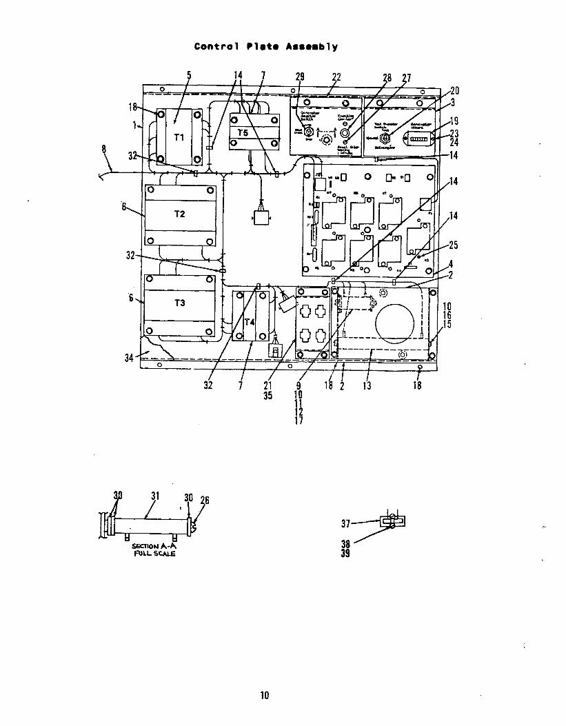
Control ?leto Asrerblv
5 If 7 29 / /I
p 0 ---- /
38 37 -_-- Ol f - --- / / 0 ----- - 1/20
/ I .
18-, 0 mh 19 f / a\ 0
r Tl T5 \ 8 0 \Q
\ 322 w
i c 0 I A
” Yl T2 I I d MI II II
32-
/ I /o / /
I f I I / / / I I
9 I
10

REF PART QJ-Y PART REF PART NO. NO. USED DESCRIPTION NO. NO.
1 301-9070 1 2 301-9224 3 301-9289 : 4 300-2939 1 5
315-0621-01 1 315-0621-03 1 315-0621-02 1 315-0621-04 1
6
315-0641-02 2 315-0641-01 2 315-0641-03
315-0618-02 315-0618-01 315-0618-03
315-0619-02 315-0619-01 315-0619-03
7 315-0620-02 315-0620-01 315-0620-03
8 338-1915 338-1890
338-1916 9 304-0139
10 304-0015 11 304-0292 12 813-0112
13 304-0037
2
Control Plate Assembly
Plate, Door Panel, Clock Bracket, Mountino - Control Board, Circuit --Printed Tr;;;f;;;;r, Control (Tl)
347. 380. 416 Volt 208. 240. 480 600.Volt
Volt
Transformer, Control (T2, T3) 30 Amp
347, 380, 416 Volt 208, 240, 480 Volt 600 Volt
60 Amp 347. 380. 416 Volt 208. 240; 480 Volt 600 Volt
100 And 200 Amp 347, 380, 416 Volt 208, 240, 480 Volt 600 Volt
Transformer, Control (T4, T5) 347, 380, 416 Volt 208, 240, 480 Volt 600 Volt
Harness, Wiring - Cabinet Main 120 Volt 208, 240, 347. 380, 416,
480 Volt 600 Volt
Resistor, Fixed Washer, Centering Insulator. Resistor Screw, Machine - Round Head
(HO - 32 x 2.5") Resistor, Fixed
QTY PART USED DESCRIPTION
14 332-2791-01 5 15 813-0116 1
16 850-0030 1 17 870-0053 1
18 821-0004 42
19 302-1167 20 308-0802 21 '301-9376 22. 301-9392 23 815-0385
1
: 1 2
2 7 1
2
1
1
3
1
3 1 1
:
1
24 870-0183 25 332-2774 26 813-0111
27 815-0538
28 320-0104
29 308-0771
30 508-0015
31 304-0775,
32 332-2791-02 34 306-3275 35 98-5434 37 332-2648 38 815-0110
39 815-0116
Clamp, Locking Screw, Machine - Round Head
(#lo - 32 x 6.5") Washer, Lock (#lo) Nut, Hex - Machine Screw
(#lo - 32) Screw, Lock - Flange (#lo -
32 x .31") Meter, Totalizing - Time Switch, Toggle - Panel, Connector Bracket, Control Screw, Machine - Round Head
(#6 - 32 x .5") Nut, Hex - ET (#6 - 32) Tie, Cable Screw, Machine - Round Head
(#lO - 32 x 2") Screw, Machine - Round Head
(#8 - 32 x .5") Limiter, Cranking (3-Wire
Start Units Only) Switch, Selector (3-Wire
Start Units Only) Washer, Flat - IGulator (#lo)
(3-Wire Start Units Onlvl Resistor, Fixed (J-Wire Start
Units Only) Clamp, Locking Cover, Component Silkscreen, Panel - Connector
*Block, Terminal - Sectional *Screw, Machine - Fillister Head
(HO - 32 x .875') *Screw. Machine - Fillister Head
(#lo-- 32 x .S")
* Used on Voltage Code 120 Volt Units Only.
11

26
\
B 24
REF PART No. No.
3 870-0212 5 821-0005
7 98-5387 8 98-5589 9 518-0439
10 425-1798 11 98-5431 i2 850-0020 13 812-0068
14 853-0003 15 332-2686 16 332-2790 17 870-0131
QTY USED
:11
3 1
:
: 2
2
: 1
16 6
5
PART DESCRIPTION
Nut, Lock (3/8 - 16) Screw, Self-Locking - Flanged
(HO - 32 x l/2") Label, Danger Tag, Caution Clip, Receptacle Clamp, Cable Tag, Caut ion Washer, Lock (#6) Screw, Machine - Round Head
(#6 - 32 x 1") Washer, Lock - ET (#6) Spacer, Time Cap, Base - Snap-In Nut, Hex - ET (#lo - 32)
REF PART QW PART NO. NO. USED DESCRIPTION
18 301-9072 19 98-2472 21 301-9387 22 301-9378 23 306-3275
xi 3:zz 26 332-0942 28 98-5435 29
98-5471 98-5540 98-5514 98-5467
30 323-1226
: 1
: 1
1; 1
: 1
:
Box, Control Label, UL Bracket, Connector Panel, Block - Terminal Cover, Component Tag. Caution Mount, Tie - Cable Tie, Cable Label, Bracket Label, Cover
120 Volt 347, 380, 416 Volt 208, 240. 480 Volt 600 Volt
Plug, Bypass
12

REF PART No. No.
1.
PART REF PART DESCRIPTION No. No.
3 *Nut, Hex (#lo - 32) 3 *Washer, Lock (#lo) 3 *Washer, Flat (#lo) 3 *Lug, Solderless - 1 *Screw, Machine - Round Head
_ (Cl0 - 32 x a/4")' 3 *Washer, Lock - IT (NO). 2 *Screw, Machine - Round Head
(#lo - 32 x l/2") 2 *Nut, Hex (l/4 - 20) 2 *Washer, Lock (l/4) ’ 2. *Washer, Flat (l/4)
2 3 4 5
6 854-0010 7 813-0100
8 862-0001 850-0040 526-0052
870-0053 850-0030 526-0049 332-1572 - 8X3-0103
QN PART USED DESCRIPTION
11 332-1320 12 332-1349 13 332-0773 14 332-1348 15 854-0014 16 812-0158
17 332-2677
98-4963 C232
2 *Spacer, Bar - Neutral
: *Insulator, Bar - Neutral *Connector, Bar - Neutral
2 *Spacer, Bar - Neutral- 1 2 *Washer, Lock - IT (l/4) 2 *Screw, Machine - Round Head
(l/4 - 20 x 2”) 1 Bar Kit, Neutral (Includes
Parts Marked *) - - *Label, Torque . *Intstructions
* Parts Included In 332-2677 Neutral Bar Kit.
13

REF PART No. No.
1 862-0001 2 850-0040 3 332-1573 4 812-0153
5 854-0014 6 812-0151
7 526-0052 6 332-1320
QJ-Y PART USED DESCRIPTION
z *Nut, Hex (l/4 - 20) -Washer, Lock (l/4)
3 *Lug, Solderless 1 *Screw, Machine - Round Head
(l/4 - 20 x 1”) 5 *Washer, Lock - IT (l/4) 3 *Screw, Mach’ine - Round Head
(l/4 - 20 x 3/4”) 2 *Washer, Flat (l/4) 2 *Spacer, Bar - Neutral
REF PART QTY PART No. No. USED DESCRIPTION
9 332-1349 2 *I&ulator, Bar - Neutral 10 332-0772 1 *Connector, Bar - Neutral 11 332-1348 12 812-0158
s *Spacer, Bar - Neutral *Screw, Machine - Round Head
(I/4 - 20 x 2”) 13 332-2782 1 Bar Kit, Neutral (Includes
- Parts Marked *) -. I - 98-5404 1 *Label, Caution
C232a 1 *Instructions
* Parts Included In 332-2782 Neutral Bar Kit.
14

Neutral Bar (200 Amp)
' 2
&--
6 -
-
REF PART QTY PART REF PART QTY PART NO. NO. USED DESCRIPTION NO. NO. USED DESCRIPTION
1 2 3
862-0015 850-0045 332-1480 800-0030
854-0017 BOO-0027
862-0001 850-0040 526-0052 332-1320
3 *Nut, Hex (S/16 - 18) 11 332-1349 2 *Insulator, - Bar Neutral 3 *Washer, Lock (S/16) 12 332-0772 1 *Connector, - Bar Neutral 3 *Lug, Solderless 13 332-1348 2 1 *Screw, Cap - Hex Head (S/16
*Spacer, - Bar Neutral - 14 854-0014 2 *Washer, -
18 x 1 l/4") Lock IT (l/4)
15 812-0158 ‘2 *Screw, - Machine Round Head
z *Washer, Lock - IT (S/16) *Screw, Cap - Hex (S/16
(l/4 - 20 x 2") - 18 x 16 332-2783 1
7/8") Bar Kit, Neutral (Includes
2 *Nut, Hex (l/4 - 20) Parts Marked *)
98-5405 1 *Label, Caution 2 *Washer, Lock (l/4) C232a 1 *Instructions 2 *Washer, Flat (l/4) 2 *Spacer, Bar - Neutral
* Parts Included In 332-2783 Neutral Bar Kit.
15

Exerciser Clock
REF PART QTY PART NO. NO. USED DESCRIPTION
1 338-1880 2
307-2177 307-2178
3 301-9224 4 812-0068
1 Harness, Wiring - Clock Switch, Time (Includes Cover
And Omitting Screws) 1 60 Hertz
: 50 Hertz
. .
fanel, Clock 2 Screw, M&Tine - Round Head
(#6 - 32 x 1”) t
REF PART NO. NO.
5 853-0003 6 332-2686 7 307-2396 8 821-0005
-9 301-9659
QT’f PART USED DESCRIPTION
2 Washer, Lock - ET (#6) 2 Spacer, Timer 7 Screw, Omitting 4 Screw, Self Locking - Flanged
(It10 - 32 x l/2”) _ 1 Cover, Terminal I
16

Exerciser Clock
REF PART QTY PART REF PART QTY PART NO. NO. USED DESCRIPTION NO. NO. USED DESCRIPTION
1 301-9989 1 Plate, Clock 3 338-2150 2 307-2581 1 Clock, Exerciser - 120 VAC 4 812-0061 :
Harness, Wiring - Clock Screw, Machine - Round Head
(#6 - 32 x 3/B")
17

Battery Charger
REF PART QW No. No. USED
1 301-9304
2 300-2946 3 302-0807 4 338-1856
5 321-0175 1 6 815-0428 4
PART DESCRIPTION
Bracket, Charger - Battery (Includes Socket Housing)
Board, Circuit - Printed Meter, Ampere - DC Harness, Wiring - Battery
Charger Holder, Fuse - Screw, Pan Head - ET (#lo -
32 x 3/8”)
REF PART No. NIT.
7 321-0174 10 821-0005
11 98-5407
12 323-1261
in PART USED DESCRIPTION
1 Fuse, 5 Amp 4 Screw, Self Locking - Flanged
(#IO - 32 x l/2”) 1 Label, Charger - Battery
(Not Shown) 1 Housing, Socket - 9 Pin
(Included With PCB)
18
--i . .

Programmed Transition
REF PART NO. NO.
307-1627 307-1108 307-1970 307-1159 323-1201 323-1208 812-0061
QTY PART REF PART QTY PART USED DESCRIPTION NO. NO. USED DESCRIPTION
*Relay, Delay - Time 870-1183 2 *Nut, Hex - ET (#6 - 32) 1 0.500 - 5.000 Set 332-0942 6 *Tie, Cable 1 1.500 - 15.00 Set Transition Kit, Programmed 1 5.000 - 50.00 Set (Includes Parts Marked *) : 1.000 - 300.0 Set 300-3042
*Connector, Plug 300-3043 : 0.500 - 5.000 Set
1.500 - 15.00 Set 2 *Relief, Strain 300-3044 1 5.000 - 50.00 Set 2 *Screw, Machine - Round Head 300-3086 1 1.000 - 300.0 Set
(#6 - 32 x 3/E") C241 1 *Instruct ions
* Parts Included In Programmed Transition Kit.
REF PART QTY PART NO. NO. USED DESCRIPTION
301-9497 307-1987 323-0004 307-1914 332-0942 821-0005
1 *Bracket, Relay 2 *Hold-Down, Relay
: *Socket, Relay *Relay, Preheat
8 *Tie, Cable 2 *Screw, Self Locking (#lo -
32 x l/2")
Preheat Relay
REF PART QTY PART NO. NO. USED DESCRIPTION
300-3045 1 Preheat Kit, Relay (Includes Parts Marked *)
812-0063 2 *Screw. Machine - Round Head (#6 - 32 x l/2")
853-0003 2 *Washer, Lock - ET (#6) C242 1 *Instructions
* Parts Included In 300-3045 Preheat Relay Kit.
19

Pins C Sockets
REF PART Qn PMT No. No. USED DESCRIPTI(m
1 323-1292 1 Housing, Pin - 4 2 323-1333 1 Housing, Socket - 4 3 323-1317 1 Housing, Pin - 6 4 323-1318 1 Housing, Socket - 6 5 323-1291 1 Housing, Pin - 9 6 323-1325 1 Housina, Socket - 9 7 323-1314 1 Housing, Pin - 12 8 323-1315 1 Housina. -
1 Housing: Socket
9 323-0983 Pin --12 12
10 323-0984 11 323-1252 :
Housing, Socket - 12 Housing, Pin - 15
12 323-1253 1 HousIng, Socket - 15
REF PART MO. No.
13 323-1207 14 323-1206 15 323-1194
16 323-1195
17 323-1199
18 323-1200
19 420-0487 1
PART DESCRIPTION
Housing, Pin - 24 Housing, Socket - 24 Pin, Contact (Used With
Circular Housings) Socket, Contact (Used With
Circular Housings) Pin, Contact (Used With
Rectangular Housings) Socket, Contact (Used With
Rectangular Housings) Tool, Removal - Pin
20
