the flow oil analysis in the gap of a journal bearing with a...
TRANSCRIPT
The flow oil analysis in the gap of a journal bearing with a circumferential groove 19
SCIENTIFIC PROBLEMS OF MACHINES OPERATION AND MAINTENANCE
2 (158) 2009
JAROSŁAW SĘP*
The flow oil analysis in the gap of a journal bearing with a circumferential groove
K e y w o r d s
Journal bearing, oil flow, finite element method.
S ł o w a k l u c z o w e
Łożysko ślizgowe, przepływ oleju, metoda elementów skończonych.
S u m m a r y
The article presents the research results of a simulation of oil flow in a circumferentially grooved journal bearing. A three-dimensional, adiabatic flow was considered and the Navier-Stokes equations together with the equation of energy were used to describe it. The system of equations was solved applying the finite element method. The numerical flow analyses carried out showed that an appropriately sized groove on the journal not only does not impair the load capacity of a hydrodynamic journal bearing, but it can even increase it. The calculations were also made for an analysis of flow effects in the oil film.
1. Introduction
Journal bearings with grooves or cavities in mating surfaces show, under some conditions, better properties than standard ones with smooth-surface * Faculty of Mechanical Engineering and Aeronautics, Rzeszów University of Technology,
Al. Powstańców Warszawy 8, 35-959 Rzeszów, Poland, e-mail: [email protected].
TRIBOLOGY •
J. Sęp
20
mating components [11, 12]. They are, among other things, less vulnerable to the wearing effect of oil impurities [9]. However, in the case of hydrodynamic slide bearings, grooved mating surfaces may considerably decrease load capacity [2, 3, 10]. There are works claiming that grooves always reduce the load capacity of a bearing compared with a pair of smoothly surfaced components [4]. This view is also considered right by some researches studying the hydrodynamic lubrication of slide bearings. It follows from the previous works of the author [7, 8] on the initial modelling of a spiral-grooved journal bearing that, under some circumstances, the journal grooves may enhance the bearing load capacity compared with a smooth journal bearing. The article presents the first stage of research with a view to explaining what causes the effect. A bearing with a circumferentially grooved journal was considered.
2. A model of bearing with a circumferential groove in the journal
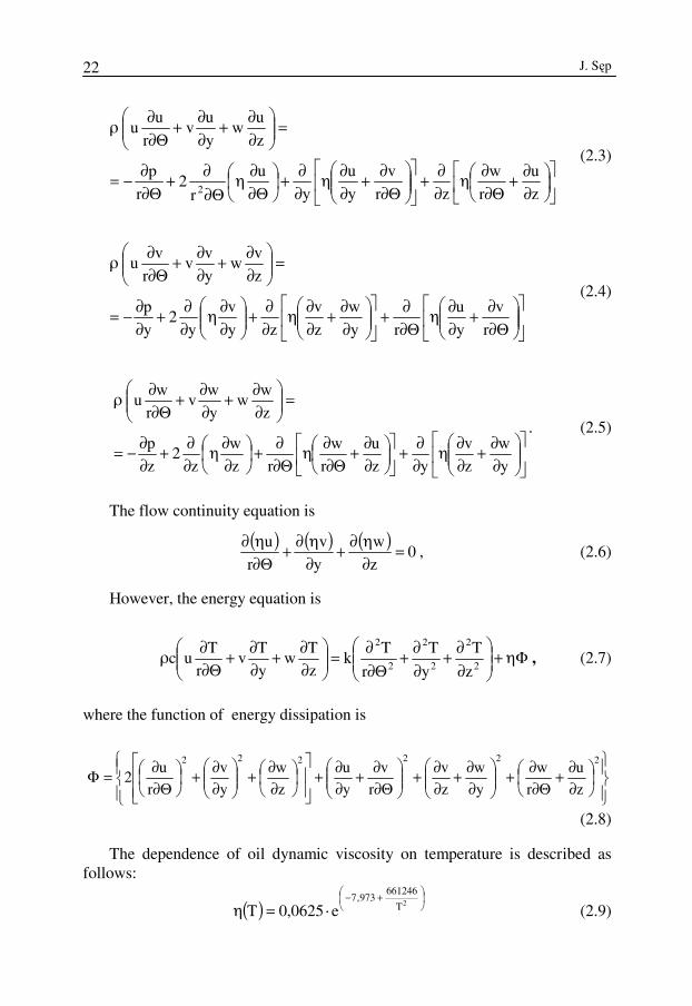
A circumferentially grooved journal bearing was schematically shown in Fig. 1. The measurements describing the groove are its width s and depth g. It was assumed that the axis of symmetry of the groove is in the middle of the bearing sleeve. While modelling the bearing, the journal and sleeve surfaces were represented by mathematical functions. The sleeve surface S1 outside the feed groove was described as
⟩⟨∈
⋅+=⟩Π⟨∈ b:0z,
r
xcosmRy,r2:0x (2.1)
The journal surface was
( )[ ]22/bzBeAry,r2:0x −−⋅+=⟩Π⟨∈ ⟩⟨∈ b:0z, (2.2) In 2.2, coefficient A and B define the depth and width of the groove,
respectively. The supply groove was modelled as a cube of length br, width sr and height hr (Fig. 2).
The depth of the groove in the surface does not exceed 100 µm, so it is comparable with the amount of oil clearance. That makes it necessary to modify the standard, hydrodynamic theory of lubrication. The typical simplifying assumptions relating to, e.g. a constant pressure value along the bearing clearance (along axis y) and lack of the effect of a number of oil speed constituent gradients, do not fit the reality. Thus, it is necessary to consider three- dimensional flow described by the Navier-Stokes equations as well as energy and continuity equations. The following assumptions were made for the analysis of oil flow in the examined bearing: − Oil is Newtonian liquid. − Flow is laminar.

The flow oil analysis in the gap of a journal bearing with a circumferential groove 21
− Flow at a fixed time t (quasi-static model) is considered. − There is no field of body forces. − Oil is incompressible. − Oil density is independent of temperature. − Oil viscosity depends only on temperature. − Thermal conditions are fixed. − Specific heat and oil thermal conductivity coefficients are constant values.
Fi 1
β
r
A-A
m
Θ
ωR
D
A
0d
b/2
A
b
B
s
g
Fig. 1. Journal bearing with circumferentially grooved journal: D(R) – diameter (radius) of the sleeve, d – diameter (radius) of the journal, b – width of the bearing, s – width of the groove,
g – depth of the groove, m – eccentricity of the journal centre O1 relative to the sleeve centre O2, W – bearing load capacity, Wx – load capacity component in the direction of axis x, Wy – load
capacity component in the direction of axis y, β – attitude angle , θ – angular coordinate measured from the maximum height of the bearing clearance, ω – angular velocity of the journal
Rys. 1. Łożysko ślizgowe z czopem z obwodowym rowkiem: D(R) – średnica (promień) panewki, d – średnica (promień) czopa, b – szerokość łożyska, s – szerokość rowka, g – głębokość rowka,
m – mimośrodowość środka czopa O1 względem środka panewki O2 , W – nośność łożyska, Wx – składowa nośności w kierunku osi x, Wy – składowa nośności względem osi y , β – kąt
położenia linii środków, Θ – współrzędna kątowa mierzona od miejsca, gdzie wysokość szczeliny smarowej jest największa, ω – prędkość kątowa czopa
The radius of curvature of a lubricating film is so large, compared with the
film thickness, that it is satisfactory to work with rectangular coordinates referred to the film surfaces (Fig.2). For the above assumptions, the Navier-Stokes equations are as follows [1]:
B
J. Sęp
22
∂∂+
Θ∂∂η
∂∂+
Θ∂
∂+∂∂η
∂∂+
Θ∂∂η
Θ∂∂+
Θ∂∂−=
=
∂∂+
∂∂+
Θ∂∂ρ
z
u
r
w
zr
v
y
u
y
u
r2
r
p
z
uw
y
uv
r
uu
2
(2.3)
Θ∂
∂+∂∂η
Θ∂∂+
∂∂+
∂∂η
∂∂+
∂∂η
∂∂+
∂∂−=
=
∂∂+
∂∂+
Θ∂∂ρ
r
v
y
u
ry
w
z
v
zy
v
y2
y
p
z
vw
y
vv
r
vu
(2.4)
∂∂+
∂∂η
∂∂+
∂∂+
Θ∂∂η
Θ∂∂+
∂∂η
∂∂+
∂∂−=
=
∂∂+
∂∂+
Θ∂∂ρ
y
w
z
v
yz
u
r
w
rz
w
z2
z
p
z
ww
y
wv
r
wu
. (2.5)
The flow continuity equation is
( ) ( ) ( )0
z
w
y
v
r
u =∂η∂+
∂η∂+
Θ∂η∂
, (2.6)
However, the energy equation is
Φη+
∂∂+
∂∂+
Θ∂∂=
∂∂+
∂∂+
Θ∂∂ρ
2
2
2
2
2
2
z
T
y
T
r
Tk
z
Tw
y
Tv
r
Tuc , (2.7)
where the function of energy dissipation is
∂∂+
Θ∂∂+
∂∂+
∂∂+
Θ∂
∂+∂∂+
∂∂+
∂∂+
Θ∂∂=Φ
222222
z
u
r
w
y
w
z
v
r
v
y
u
z
w
y
v
r
u2
(2.8)
The dependence of oil dynamic viscosity on temperature is described as follows:
( )
+−
⋅=η2T
661246973,7
e0625,0T (2.9)
The flow oil analysis in the gap of a journal bearing with a circumferential groove 23
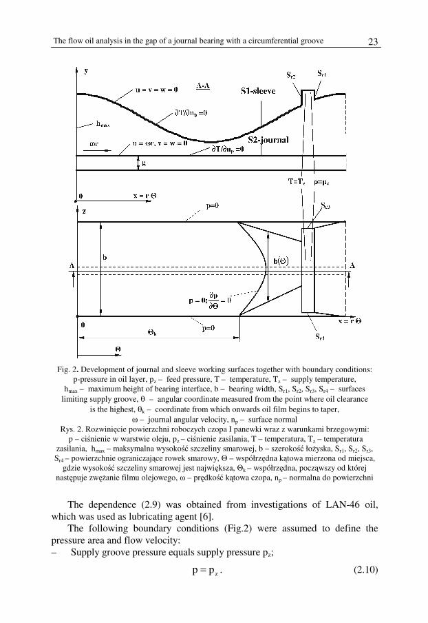
Fig. 2. Development of journal and sleeve working surfaces together with boundary conditions: p-pressure in oil layer, pz – feed pressure, T – temperature, Tz – supply temperature,
hmax – maximum height of bearing interface, b – bearing width, Sr1, Sr2, Sr3, Sr4 – surfaces limiting supply groove, θ – angular coordinate measured from the point where oil clearance
is the highest, θk – coordinate from which onwards oil film begins to taper, ω – journal angular velocity, np – surface normal
Rys. 2. Rozwinięcie powierzchni roboczych czopa I panewki wraz z warunkami brzegowymi: p – ciśnienie w warstwie oleju, pz – ciśnienie zasilania, T – temperatura, Tz – temperatura
zasilania, hmax – maksymalna wysokość szczeliny smarowej, b – szerokość łożyska, Sr1, Sr2, Sr3, Sr4 – powierzchnie ograniczające rowek smarowy, Θ – współrzędna kątowa mierzona od miejsca,
gdzie wysokość szczeliny smarowej jest największa, Θk – współrzędna, począwszy od której następuje zwężanie filmu olejowego, ω – prędkość kątowa czopa, np – normalna do powierzchni
The dependence (2.9) was obtained from investigations of LAN-46 oil, which was used as lubricating agent [6].
The following boundary conditions (Fig.2) were assumed to define the pressure area and flow velocity: – Supply groove pressure equals supply pressure pz;
zpp = . (2.10)

J. Sęp
24
– Oil pressure on the exit sleeve edges in the axial direction equals ambient pressure which was assumed to be the reference point equal 0.
( ) ( ) .0bz,p0z,p ==Θ==Θ (2.11)
– Pressure in the idle area of the oil clearance equals zero;
( ) .0z,p n =Θ (2.12)
– end of oil film is the point locus where the pressure equals the ambient pressure and pressure gradient equals zero;
,0p
oraz0pz,x
z,x=
Θ∂∂=
Θ=ΘΘ=Θ (2.13)
– Journal speed equals ωr, and the journal does only rotary motion. Therefore, on the S2 surface:
.0wv,ru 2S==ω= (2.14)
– The sleeve is motionless; therefore, on the S1 surface and on the surfaces
limiting the feed groove:
,0wvu 4Sr,3Sr,2Sr,1Sr,1S=== (2.15)
– In the oil clearance, the following dependencies are also met:
),2(p)0(p Π=Θ==Θ (2.16)
),2(u)0(u Π=Θ==Θ (2.17)
),2(v)0(v Π=Θ==Θ (2.18)
).2(w)0(w Π=Θ==Θ (2.19)
As a consequence of assuming the adiabatic flow model, the following boundary conditions were postulated to define the temperature field: – The groove is totally filled with oil at the temperature denoted as Tz (the
effect of streams getting mixed in the groove was ignored, since their mixing in the oil film was assumed).
– The stream of heat penetrating through the journal and the sleeve surfaces equals 0. Therefore;
0n
T
n
T2S1S =
∂∂=
∂∂
(2.20)
where n means normal to the surface
The flow oil analysis in the gap of a journal bearing with a circumferential groove 25
Additionally, it was assumed that
( ) ( )Π=Θ==Θ 2T0T (2.21)
3. Calculation methodology
The set of equations (2.3)–(2.7) was made discrete by applying the method of finite elements. One of the variants of the weighted, residual method, the Garlekin method, was used. The obtained set of equations was made linear, making use of the Newton-Raphson method and than solved by the Gauss elimination method.
From tetrahedral 78672 to 101232, 4-node, spatial elements were generated in the oil clearance volume, depending on the size of the groove. The mesh of the finite elements is shown in Fig. 3. The solution procedure was carried out using the ADINA 8.1 programme packets.
The above presented calculation method was verified by comparing the obtained results with those found in the literature of experimental research results [5].
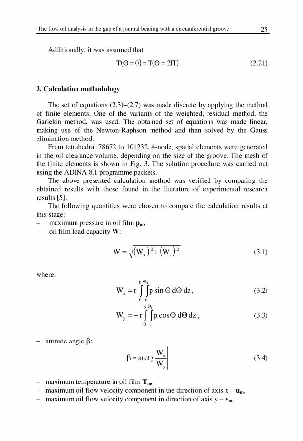
The following quantities were chosen to compare the calculation results at this stage: – maximum pressure in oil film pm, – oil film load capacity W:
( ) ( ) 2y
2x WWW += (3.1)
where:
∫ ∫Θ
ΘΘ=b
0 0
x
k
dzdsinprW , (3.2)
∫ ∫Θ
ΘΘ−=b
0 0
y
k
dzdcosprW , (3.3)
– attitude angle β:
y
x
W
Warctg=β , (3.4)
– maximum temperature in oil film Tm, – maximum oil flow velocity component in the direction of axis x – um, – maximum oil flow velocity component in direction of axis y – vm,

J. Sęp
26
– maximum oil flow velocity component in the direction of axis z – wm, – oil flow rate:
∫ ∫Θ
Θ=h
0 0
o
k
dyrdw2q . (3.5)
Fig. 3. Mesh of finite elements Rys. 3. Siatka elementów skończonych
The flow oil analysis in the gap of a journal bearing with a circumferential groove 27
The calculations were done at the following values of the parameters describing the oil and the oil clearance: − Journal radius r = 0.0316 m, sleeve radius R = 0.0317275 m, − Bearing length b = 0.063 m, − Oil density ρ = 880 kg/m3, oil specific heat c = 2000 J/(kg⋅K), − Oil heat conductivity k = 0.145 W/(m⋅K), − Journal angular velocity ω = 20 rad/s, pz = 0, Tz =293 K.
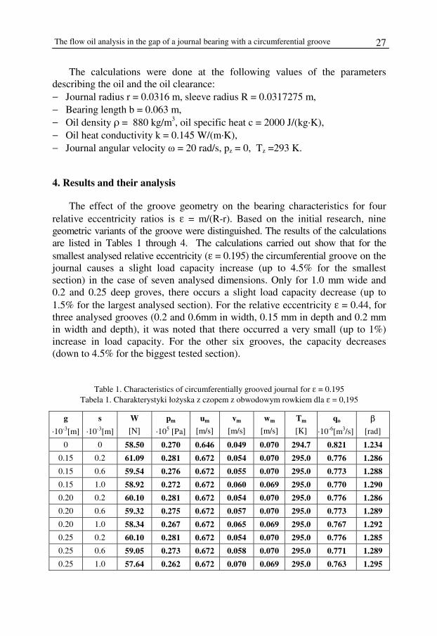
4. Results and their analysis
The effect of the groove geometry on the bearing characteristics for four relative eccentricity ratios is ε = m/(R-r). Based on the initial research, nine geometric variants of the groove were distinguished. The results of the calculations are listed in Tables 1 through 4. The calculations carried out show that for the smallest analysed relative eccentricity (ε = 0.195) the circumferential groove on the journal causes a slight load capacity increase (up to 4.5% for the smallest section) in the case of seven analysed dimensions. Only for 1.0 mm wide and 0.2 and 0.25 deep groves, there occurs a slight load capacity decrease (up to 1.5% for the largest analysed section). For the relative eccentricity ε = 0.44, for three analysed grooves (0.2 and 0.6mm in width, 0.15 mm in depth and 0.2 mm in width and depth), it was noted that there occurred a very small (up to 1%) increase in load capacity. For the other six grooves, the capacity decreases (down to 4.5% for the biggest tested section).
Table 1. Characteristics of circumferentially grooved journal for ε = 0.195 Tabela 1. Charakterystyki łożyska z czopem z obwodowym rowkiem dla ε = 0,195
g
⋅10-3[m]
s
⋅10-3[m]
W
[N]
pm
⋅105 [Pa]
um
[m/s]
vm
[m/s]
wm
[m/s]
Tm
[K]
qo
⋅10-6[m3/s]
β
[rad]
0 0 58.50 0.270 0.646 0.049 0.070 294.7 0.821 1.234
0.15 0.2 61.09 0.281 0.672 0.054 0.070 295.0 0.776 1.286
0.15 0.6 59.54 0.276 0.672 0.055 0.070 295.0 0.773 1.288
0.15 1.0 58.92 0.272 0.672 0.060 0.069 295.0 0.770 1.290
0.20 0.2 60.10 0.281 0.672 0.054 0.070 295.0 0.776 1.286
0.20 0.6 59.32 0.275 0.672 0.057 0.070 295.0 0.773 1.289
0.20 1.0 58.34 0.267 0.672 0.065 0.069 295.0 0.767 1.292
0.25 0.2 60.10 0.281 0.672 0.054 0.070 295.0 0.776 1.285
0.25 0.6 59.05 0.273 0.672 0.058 0.070 295.0 0.771 1.289
0.25 1.0 57.64 0.262 0.672 0.070 0.069 295.0 0.763 1.295

J. Sęp
28
Table 2. Characteristics of circumferentially grooved journal for ε = 0.44 Tabela 2. Charakterystyki łożyska z czopem z obwodowym rowkiem dla ε = 0,44
g ⋅10-3[m]
s ⋅10-3[m]
W [N]
pm ⋅105 [Pa]
um [m/s]
vm [m/s]
wm [m/s]
Tm [K]
qo ⋅10-6[m3/s]
β [rad]
0 0 160.05 0.786 0.733 0.399 0.154 295.8 1.703 0.963 0.15 0.2 162.97 0.884 0.774 0.216 0.175 294.9 1.962 1.117 0.15 0.6 160.33 0.853 0.781 0.217 0.174 294.9 1.955 1.120 0.15 1.0 158.05 0.826 0.785 0.218 0.173 294.9 1.947 1.122 0.20 0.2 162.86 0.883 0.774 0.216 0.175 294.9 1.962 1.117 0.20 0.6 159.31 0.839 0.869 0.217 0.173 294.9 1.951 1.120 0.20 1.0 155.74 0.801 0.880 0.217 0.171 294.9 1.939 1.125 0.25 0.2 162.85 0.883 0.774 0.217 0.173 294.8 1.962 1.117 0.25 0.6 158.09 0.825 0.939 0.217 0.173 294.8 1.948 1.122 0.25 1.0 153.01 0.773 0.965 0.217 0.173 294.8 1.929 1.129
Table 3. Characteristics of circumferentially grooved journal for ε = 0.69
Tabela 3. Charakterystyki łożyska z czopem z obwodowym rowkiem dla ε = 0,69
g ⋅10-3[m]
s ⋅10-3[m]
W [N]
pm ⋅105 [Pa]
um [m/s]
vm [m/s]
wm [m/s]
Tm [K]
qo ⋅10-6[m3/s]
β [rad]
0 0 358.20 2.102 0.719 0.354 0.256 299.4 2.716 0.688 0.15 0.2 377.47 2.515 0.982 0.229 0.277 297.4 2.854 0.794 0.15 0.6 363.36 2.279 1.220 0.230 0.274 297.4 2.842 0.801 0.15 1.0 350.69 2.155 1.180 0.231 0.273 297.4 2.826 0.810 0.20 0.2 377.11 2.505 1.037 0.230 0.277 297.4 2.854 0.794 0.20 0.6 356.39 2.203 1.447 0.231 0.273 297.4 2.834 0.806 0.20 1.0 337.87 2.032 1.393 0.231 0.269 297.3 2.812 0.822 0.25 0.2 376.69 2.501 1.053 0.230 0.277 297.4 2.854 0.794 0.25 0.6 348.94 2.128 1.571 0.231 0.271 297.4 2.826 0.812 0.25 1.0 324.46 1.928 1.474 0.231 0.265 297.3 2.794 0.834
Table 4. Characteristics of circumferentially grooved journal for ε = 0.87
Tabela 4. Charakterystyki łożyska z czopem z obwodowym rowkiem dla ε = 0,87
g ⋅10-3[m]
s ⋅10-3[m]
W [N]
pm ⋅105 [Pa]
um [m/s]
vm [m/s]
wm [m/s]
Tm [K]
qo ⋅10-6[m3/s]
β [rad]
0 0 658.40 4.540 0.725 0.117 0.318 303.5 3.304 0.467 0.15 0.2 784.78 6.911 1.990 0.069 0.346 300.9 3.392 0.572 0.15 0.6 718.97 6.155 1.917 0.066 0.340 300.7 3.376 0.558 0.15 1.0 682.15 5.926 1.670 0.069 0.335 300.6 3.358 0.598 0.20 0.2 780.75 6.828 2.088 0.066 0.346 300.9 3.396 0.572 0.20 0.6 693.45 5.977 2.137 0.066 0.337 300.6 3.364 0.595 0.20 1.0 649.57 5.756 1.868 0.075 0.330 300.6 3.338 0.608 0.25 0.2 776.83 6.749 2.022 0.066 0.346 300.9 3.394 0.573 0.25 0.6 670.96 5.856 2.129 0.067 0.343 300.5 3.352 0.603 0.25 1.0 622.57 5.624 1.881 0.080 0.325 300.5 3.314 0.615
The flow oil analysis in the gap of a journal bearing with a circumferential groove 29
At ε = 0.69, the capacity load increases for the same groove sections, as for ε = 0.44 (to 5% for the smallest section). For the rest of the sections, the load capacity decreases (to 9.5%).
For a relative eccentricity ratio of ε = 0.87, for the seven analysed grooves, there occurs an increase in load capacity (up to 19% for the smallest section); whereas, the remaining two grooves cause a load capacity decrease (to 5.5%). In all the cases analysed, the highest load capacity of the bearing occurs at the smallest investigated groove section (it is higher than in the case of a smooth journal bearing); whereas, the lowest load capacity is shown by the bearing with the largest groove considered. For the analysed bearing geometry and the assumed oil and rotational speed, a circumferential groove of the appropriate width and (section) depth enhances bearing load capacity. The load capacity changes are accompanied by those of oil flow velocity. The observed changes refer in particular to the circumferential velocity u. For the least analysed relative eccentricity value, they are still not very significant. For all the nine investigated geometric variations of the groove, the maximum velocity of the flow in the circumferential direction (um) has the same values and is by 4% higher than that for a smooth journal.
At ε = 0.44, the value of the parameter um is from 5.5% (the smallest groove) to 24.5% (the largest groove) higher than that for a bearing with grooveless journal.
An increment in relative eccentricity causes a further increase in the maximum velocity of oil flow in the circumferential direction. For ε = 0.69, it increases from 36.5% (the smallest groove) to almost 120% (the groove of 0.6 mm in width and 0.25 mm in depth). At ε = 0.87, the maximum velocity of oil flow in the circumferential direction is from more than two to almost three time as big as that in the case of a grooveless journal.
It is also noteworthy that the maximum oil film temperature in a circumferentially grooved journal bearing is smaller than that for a smooth journal bearing. The maximum temperature in a plain journal bearing occurs in the idle area halfway along the width of the bearing, right before the feed groove. In the circumferentially grooved journal bearing, the height of the bearing clearance at that place increases locally (through the groove). That brings about a decrease in the maximum temperature.
The calculated results indicate that a circumferential groove in the journal of a bearing significantly changes its characteristics compared to a standard bearing. To find out the causes of these changes, complex analyses of the phenomena in the oil film [6] were carried out.
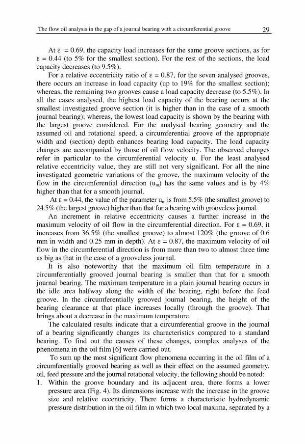
To sum up the most significant flow phenomena occurring in the oil film of a circumferentially grooved bearing as well as their effect on the assumed geometry, oil, feed pressure and the journal rotational velocity, the following should be noted: 1. Within the groove boundary and its adjacent area, there forms a lower
pressure area (Fig. 4). Its dimensions increase with the increase in the groove size and relative eccentricity. There forms a characteristic hydrodynamic pressure distribution in the oil film in which two local maxima, separated by a
J. Sęp
30
low-pressure area, appear. Increasing the groove dimensions and relative eccentricity results in the pressure maximum shifting in the direction of the bearing edge.
Fig. 4. Distribution of the hydrodynamic pressure in the oil film on the journal surface (y = r) for ε = 0.69; variant I – smooth journal, variant II – journal with the smallest investigated groove,
variant III – journal with the biggest investigated groove Rys. 4. Ciśnienie hydrodynamiczne w filmie olejowym na powierzchni czopa (y = r) dla ε = 0,69; wariant 1 – gładki czop, wariant 2 – czop z najmniejszym z badanych rowków, wariant 3 – czop
z największym z badanych rowków
The flow oil analysis in the gap of a journal bearing with a circumferential groove 31
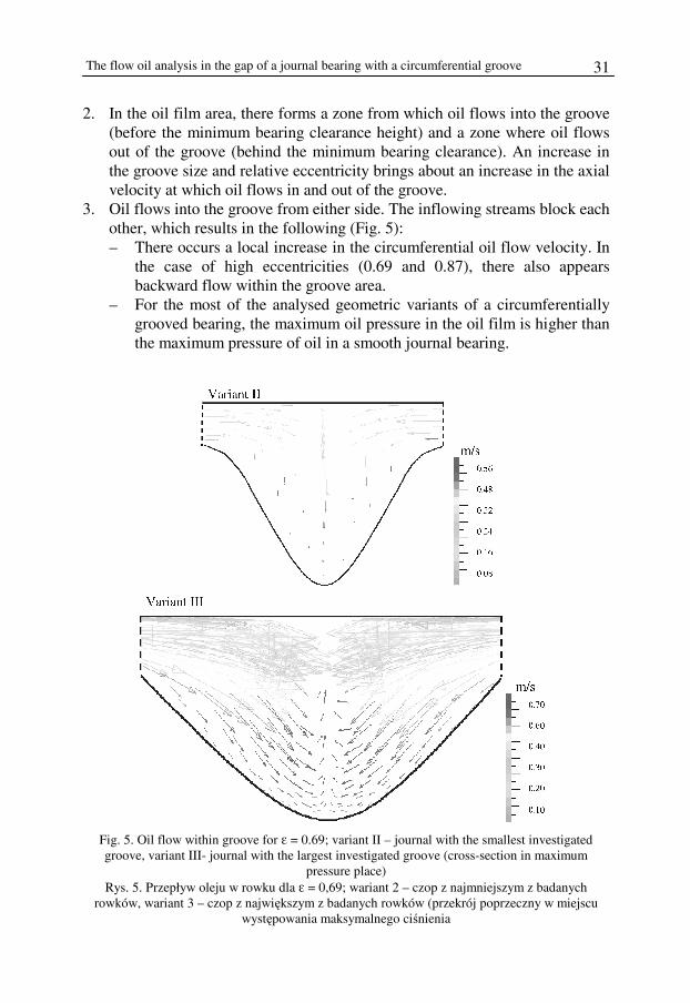
2. In the oil film area, there forms a zone from which oil flows into the groove (before the minimum bearing clearance height) and a zone where oil flows out of the groove (behind the minimum bearing clearance). An increase in the groove size and relative eccentricity brings about an increase in the axial velocity at which oil flows in and out of the groove.
3. Oil flows into the groove from either side. The inflowing streams block each other, which results in the following (Fig. 5): – There occurs a local increase in the circumferential oil flow velocity. In
the case of high eccentricities (0.69 and 0.87), there also appears backward flow within the groove area.
– For the most of the analysed geometric variants of a circumferentially grooved bearing, the maximum oil pressure in the oil film is higher than the maximum pressure of oil in a smooth journal bearing.
Fig. 5. Oil flow within groove for ε = 0.69; variant II – journal with the smallest investigated groove, variant III- journal with the largest investigated groove (cross-section in maximum
pressure place) Rys. 5. Przepływ oleju w rowku dla ε = 0,69; wariant 2 – czop z najmniejszym z badanych
rowków, wariant 3 – czop z największym z badanych rowków (przekrój poprzeczny w miejscu występowania maksymalnego ciśnienia

J. Sęp
32
4. For a small sized circumferential groove, the lowered pressure area is small and, due to an increase in the oil film maximum pressure, the load capacity of the bearing improves.
5. For all the analysed relative eccentricities, a circumferential groove of 0.15 mm in depth (60% of bearing clearance) and of up to 0.6 mm in width (four times the depth) increases the bearing load capacity. However, a groove of 0.25 mm in depth (bearing clearance) and 1 mm in width (also four times the depth) causes, for all the investigated eccentricities, a decrease in load capacity compared to a smooth journal bearing.
5. Conclusions
1. If a circumferential groove on a journal, in the case when its axis of symmetry, is halfway along the width of the sleeve and its dimensions have been appropriately selected, it can cause an increase in the bearing load capacity compared to a smooth journal bearing. This is due to a change in the oil flow conditions compared to a standard bearing.
2. Oil flows into the groove from either side, and the inflowing streams block each other’s flow in the axial direction. That results in a characteristic hydrodynamic pressure distribution, where there form two local maxima separated by a lowered pressure zone. There is also a local increase in oil flow velocity in the circumferential direction.
3. At the appropriate groove dimensions, due to the above described phenomena, hydrodynamic pressure attains higher values than those for a standard slide bearing, and the zone of lowered pressure between local extrema is small. This results in an effect of increased load capacity. However, when the groove is too big, the local maxima show smaller values than those in the case of a standard bearing. Furthermore, the pressure decrease between them is remarkable, and, in such a case, a load capacity decrease can be observed.
References
[1] Gross W.A., Matsch L.A., Castelli V., Eshel A., Vohr J.H., Wildmann M.: Fluid film lubrication. A Wiley-Interscience Publication, New York, Toronto 1980.
[2] Kang K., Rhim Y., Sung K.: A study of the oil-lubricated herringbone-grooved journal bearing-part 1: numerical Analysis. Transactions of the ASME, Journal of Tribology, vol. 118, 1996, 906–911.
[3] Kawabata N., Ozawa Y., Kamaya S., Miyake Y.: Static characteristics of the regular and reversible rotation type herringbone grooved journal bearing. Transactions of the ASME, Journal of Tribology, vol. 111, 1989, 484–490.
[4] Król M.: Badania wpływu mikrogeometrii na obciążalność poprzecznych łożysk ślizgowych. Zagadnienia Eksploatacji Maszyn, nr 1(73), 1988, 15–25.

The flow oil analysis in the gap of a journal bearing with a circumferential groove 33
[5] Merc T.: Przepływ oleju w nieroboczej części poprzecznego łożyska ślizgowego. Rozprawa doktorska, Politechnika Łódzka, Łódź 1981.
[6] Sęp J.: Właściwości filmu olejowego w poprzecznych łożyskach ślizgowych z nie-typową geometrią czopa. Oficyna Wydawnicza Politechniki Rzeszowskiej, Rzeszów 2006.
[7] Sęp J.: Three-dimensional hydrodynamic analysis of a journal bearing with a two-component surface layer. Tribology International, vol. 38, 2005, 97–104.
[8] Sęp J.: Trójwymiarowa hydrodynamiczna analiza łożyska z czopem ze śrubowym rowkiem. Tribologia nr 5, 2003, 447–458.
[9] Sęp J., Kucaba-Piętal A.: Experimental testing of journal bearings with two-component surface layer in the presence of an oil abrasive contaminant. Wear, vol. 249, 2001, 1090– –1095.
[10] Stolarski T.A., Khan M.Z.: Steady-state performance of oil lubricated helical grooved journal bearings. Tribology Transactions, vol. 38, 1995, 459–465.
[11] Wierzcholski K.: A new concept of the changes of memory capacity of fluid dynamics HDD micro-bearings. Tribologia, vol. 4 (220), 2008, 267–273.
[12] Wierzcholski K., Miszczak A.: Capacity enhancement in HDD conical micro-bearings. Tribologia, vol. 4 (226), 2009, 251–258.
Manuscript received by Editorial Board, June 19th, 2009
Analiza przepływu oleju w łożysku ślizgowym z rowkiem na czopie
S t r e s z c z e n i e
W artykule przedstawiono rezultaty komputerowej symulacji przepływu oleju w poprzecznym łożysku ślizgowym z rowkiem na czopie. Rozważono trójwymiarowy adiabatyczny przepływ oleju opisany równaniami Naviera-Stokesa wraz z równaniami ciągłości przepływu i energii. Układ równań rozwiązano metodą elementów skończonych. Wyniki analiz numerycznych wskazały, że obwodowy rowek na czopie o odpowiednio dobranych wymiarach nie powoduje zmniejszenia nośności łożyska. Na podstawie przeprowadzonych obliczeń zidentyfikowano także zjawiska przepływowe w filmie olejowym analizowanego łożyska.

H. Tomaszek, M. Ważny
34