the first law of thermodynamics copyrighted...
TRANSCRIPT

1
1
The First Law ofThermodynamics
1.1 ELEMENTS OF THERMODYNAMICS TERMINOLOGY
The first step in the thermodynamic analysis of anything must be the definitionof the entity that is being subjected to analysis. We refer to this entity (col-lection of matter, region in space) as a system. Although the need for exe-cuting this first move and for doing it once and unambiguously is obvious,the temptation is great to assume the system definition itself obvious and omitit. This is a source of confusion, if not outright error. Paradoxical differencesbetween two results claimed by two experts who attack ‘‘the same problem’’are often explained by the realization that the two problem solvers were men-tally addressing different systems. As we will see very soon, the precise def-inition of the system is critical when determining the location and magnitudeof thermodynamic irreversibility.
The tendency to forget to define the system is due mainly to tradition. Inconsiderably older disciplines such as solid-body mechanics, the system isindeed obvious, as the mere sketching of a body focuses the attention of bothproblem solver and critic. In fluid mechanics and heat transfer, the system isagain understood once the boundary conditions necessary for solving theNavier–Stokes equations are specified. However, even in fluid mechanics andheat transfer, the unambiguous definition of the system is a must if the methodis order of magnitude or scale analysis [1]—that is, if the analyst replacesthe Navier–Stokes equations with approximate algebraic statements that can-not be subjected to boundary conditions.
To define the system means also to identify sharply the system’s environ-ment, or surroundings. The environment is the portion of matter or region inspace that resides outside the system selected for analysis. What differentiatesbetween the system and its environment is the surface called boundary. Onevery important defining feature that sometimes falls prey to the same forcesof tradition is that the boundary is a surface, not another system (note thatthe thickness of a surface is zero; therefore, the boundary can neither contain
COPYRIG
HTED M
ATERIAL

2 THE FIRST LAW OF THERMODYNAMICS
Figure 1.1 Discontinuity of entropy transfer through an incorrect boundary.
matter nor fill a volume in space). Said another way, the value of a propertythat is measured at a point on the surface called boundary must be shared byboth the system and the environment because, after all, the system and theenvironment are in contact at that point.
To see the importance of this observation, consider the heat interaction Qbetween two fluid masses whose absolute temperatures are different, TH �TL. The thermal conductivities of the two fluids (or their states of agitation)are such that each fluid can be regarded as isothermal. The temperature dropTH � TL occurs through the wall. If the wall thickness is small relative to thesize of the fluid masses (e.g., the skin of a hot-air balloon in flight), it istempting to regard the wall as the boundary between, say, the system (TH)and the environment (TL). This incorrect choice is shown in Fig. 1.1. Itsdrawback is that unlike the heat transfer Q, the entropy transfer Q /T is notconserved as it passes through the boundary. If made, this choice serves as apermanent source of confusion: The unexperienced analyst has trouble decid-ing whether to use TH or TL in the denominator of Q /T, and the engineeringcomponent that is responsible for the generation of entropy (Sgen) is effectivelyhidden from view. The capricious augmentation of entropy transfer through‘‘boundaries’’ of the kind shown in Fig. 1.1 perpetuates the mystery thatsurrounds the concepts of entropy, entropy transfer, and entropy generation.
Proper ways to select a system boundary between the masses TH and TL
are exhibited in Fig. 1.2a–c. Because the temperature varies continuouslyacross each boundary, the heat transfer and the entropy transfer are conserved.In Fig. 1.2a the wall (the temperature drop) is situated outside the TH system,and for this reason the entropy generation due to the system–environmentheat interaction can be termed ‘‘external.’’ The opposite choice is made inFig. 1.2b, where the entropy-generation effect is ‘‘internal’’ relative to the TH
system. Figure 1.2c shows that the system can be divided further into sub-

ELEMENTS OF THERMODYNAMICS TERMINOLOGY 3
Figure 1.2 Continuity of entropy transfer, heat transfer, and temperature through cor-rect boundaries.
systems if the precise identification of the source of entropy generation (thewall) is one of the objectives of the thermodynamic analysis.
The observation that properties must vary continuously across the surfacechosen as boundary is general. The discontinuity of absolute temperature wasused in Fig. 1.1 only for the purpose of illustration.
The boundary and the interactions that are present at the boundary playroles in the structure (organization) of the analysis devoted to solving a prob-lem. One feature that must be recognized at an early stage is whether theboundary is crossed by the flow of mass. A system defined by a boundaryimpermeable to mass flow is a closed system. Most of the systems discussedin connection with the establishment of relationships between thermodynamicproperties at equilibrium are closed systems (Chapters 4, 6, and 7). Con-versely, systems whose defining boundaries can be crossed by the flow ofmass are open systems, or flow systems. The engineering thermodynamics ofopen systems often relies on a special terminology; for example, the ther-modynamic system itself is referred to as the control volume, the systemboundary is the control surface, and the particular patches of the boundarythat are crossed by mass flow are the inlet and outlet ports.
The condition, or the being, of a thermodynamic system at a particularpoint in time is described by an ensemble of quantities called thermodynamicproperties. We refer to the condition described by properties as state. Not allthe quantities (numerical values) that the analyst calculates in connection witha certain system are thermodynamic properties. Thermodynamic propertiesare only those quantities whose numerical values do not depend on the historyof the system, as the system evolves between two different states. Quantitiessuch as pressure and temperature are properties because their values depend

4 THE FIRST LAW OF THERMODYNAMICS
strictly on the instantaneous condition during which they are measured. Ex-amples of quantities that are not thermodynamic properties are work, heatand mass transfer, entropy transfer, entropy generation (Fig. 1.2), lost avail-able work, and lost exergy.
The thermodynamic properties that we encounter in engineering are quitenumerous: It seems that each generation has added to the list one or morenew properties that proved to be useful relative to the engineering challengesof the period. Some properties can be measured directly (e.g., pressure, tem-perature, volume), whereas others can be derived based on such measurements(e.g., internal energy, entropy, enthalpy, exergy). Thermodynamic propertieswhose values depend on the size of the system are called extensive properties(e.g., volume, entropy, internal energy). Intensive properties are those whosevalues do not depend on the size of the system: for example, pressure andtemperature. The collection of all the intensive properties of a system consti-tutes the intensive state.
A certain phase of a system is the collection of all the parts of the systemthat have the same intensive state and the same per-unit-mass values of theextensive properties. For example, liquid droplets dispersed in a liquid–vapormixture in equilibrium have the same pressure, temperature, specific volume,specific enthalpy, and so on; taken together, the droplets represent the liquidphase.
Finally, we use the concept of process as a one-word reference to thechange of state from an initial state to a final state. To know the processmeans to know not only the end states but also the interactions experiencedby the system while in communication with its environment (e.g., work trans-fer, heat transfer, entropy transfer, mass transfer). The path of the process isthe history, or the succession of states, followed by the system from the initialto the final state. Stressing again the fundamental difference between ther-modynamic properties and quantities that are not properties, note that thechanges in nonproperties depend not only on the end states but also on thepath.
The thermodynamic cycle is a special process in which the final state co-incides with the initial state. Starting with Sadi Carnot’s 1824 memoir [2],the concept of cycle evolved into a key concept in the field of power engi-neering and a vehicle for logical deduction in thermodynamics theory.
1.2 THE FIRST LAW FOR CLOSED SYSTEMS
Two principles of classical thermodynamics must be stressed in an advancedtreatment such as this. One principle is the equivalence of work transfer andheat transfer as possible forms of energy interactions. This principle is en-capsulated in the First Law of Thermodynamics, which, in Max Planck’swords, ‘‘is nothing more than the principle of the conservation of energyapplied to phenomena involving the production or absorption of heat’’ [3].

THE FIRST LAW FOR CLOSED SYSTEMS 5
The second principle is the inherent irreversibility of all processes that occurin nature. Everything flows in one direction, from high to low. It is the irre-versibility, or the generation of entropy, that prevents humans from extractingthe most possible work from various processes and from doing the most withthe work that is already at our disposal. This second principle is summarizedby the Second Law of Thermodynamics.
Traditionally, the first law is discussed first and the second law second.This ordering is based apparently on views—both questionable—that the firstlaw is older than the second law and that the concept of internal energydefined by the first law is somehow easier to grasp than the concept of entropyintroduced by the second law. The first view is fueled by the misinterpretationof statements of the kind quoted from Max Planck in the preceding paragraph:What is relatively older than the second law is the principle of conservationof energy known in mechanics, not the First Law of Thermodynamics. Thefirst and second laws emerged together from the writings of William JohnMacQuorn Rankine, Rudolph Clausius, and William Thomson (Lord Kelvin)in the early 1850s (consult Ref. 4): They had to emerge together in order toresolve the conflict between Sadi Carnot’s theory, which assumed the con-servation of ‘‘caloric,’’ and the growing evidence that work through frictioncan serve as an endless source of caloric. The second view—the feeling thatinternal energy is easier to understand than entropy—is again fueled by theengineer’s relative familiarity with the aging concept of mechanical energy,not with internal energy.
The questioning of tradition aside, in this treatment I also start with thefirst law because, above all, this is a review of the student’s first encounterwith engineering thermodynamics, not a review of the history of the subject.Note that a number of captivating historical accounts already exist in bookform [4–7] or in certain prefaces and introductions that convey some of thehistorical flavor [8–10]. Further observations on the historical developmentof the First Law of Thermodynamics are presented at the end of the chapter.
Consider the closed system shown schematically in Fig. 1.3: If this systemexperiences a change of state from the initial state (1) to the final state (2),the First Law of Thermodynamics requires that
Q1–2 � W1–2 � E2 � E1 (1.1)
Heattransfer
Worktransfer
Energychange
(Property)
Energy interactions(Nonproperties)
The difference between the net heat input Q1–2 and the net work outputW1–2 represents the change in the thermodynamic property called energy. Thefirst law proclaims the existence of energy as a thermodynamic property.
6 THE FIRST LAW OF THERMODYNAMICS
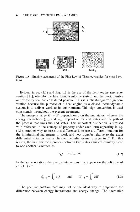
Figure 1.3 Graphic statements of the First Law of Thermodynamics for closed sys-tems.
Evident in eq. (1.1) and Fig. 1.3 is the use of the heat-engine sign con-vention [11], whereby the heat transfer into the system and the work transferout of the system are considered positive. This is a ‘‘heat-engine’’ sign con-vention because the purpose of a heat engine as a closed thermodynamicsystem is to deliver work to its environment. This sign convention is usedconsistently throughout the present treatment.
The energy change E2 � E1 depends only on the end states, whereas theenergy interactions Q1–2 and W1–2 depend on the end states and the path ofthe process that links the end states. This important distinction is stressedwith reference to the concept of property under each term appearing in eq.(1.1). Another way to stress this difference is to use a different notation forthe infinitesimal increments in work and heat transfer relative to the exactdifferential notation that applies to the infinitesimal change in E. For thisreason, the first law for a process between two states situated infinitely closeto one another is written as
�Q � �W � dE (1.2)
In the same notation, the energy interactions that appear on the left side ofeq. (1.1) are
2 2
Q � � �Q and W � � �W (1.3)1–2 1–21 1
The peculiar notation ‘‘�’’ may not be the ideal way to emphasize thedifference between energy interactions and energy change. The alternative
THE FIRST LAW FOR CLOSED SYSTEMS 7
Figure 1.4 Path dependence of the energy interactions Q1–2 and W1–2.
used by Truesdell [12] consists of introducing the concept of time in thedescription of the process (see the bottom of Fig. 1.3). In this new description,state (1) is the condition of the system at time t1, state (2) is the condition attime t2, and the net energy interactions Ql–2 and W1–2 are the time integrals
t t2 2
˙ ˙Q � � Q dt, W � � W dt (1.4)1–2 1–2t t1 1
Quantities Q and W are the instantaneous heat transfer rate and themechanical-power output, respectively (note that the Q and W notations areused routinely in the analysis of open systems in steady flow). By using thenotation of eqs. (1.4), the First Law of Thermodynamics for a closed systemcan be written on a per-unit-time basis as
dE˙ ˙Q � W � (1.5)dt
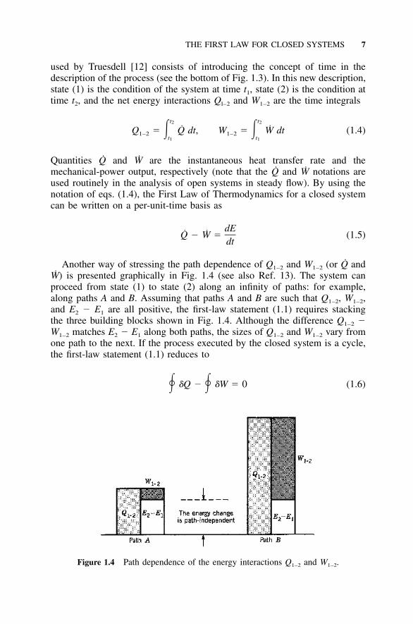
Another way of stressing the path dependence of Q1–2 and W1–2 (or Q andW) is presented graphically in Fig. 1.4 (see also Ref. 13). The system canproceed from state (1) to state (2) along an infinity of paths: for example,along paths A and B. Assuming that paths A and B are such that Q1–2, W1–2,and E2 � E1 are all positive, the first-law statement (1.1) requires stackingthe three building blocks shown in Fig. 1.4. Although the difference Q1–2 �W1–2 matches E2 � E1 along both paths, the sizes of Q1–2 and W1–2 vary fromone path to the next. If the process executed by the closed system is a cycle,the first-law statement (1.1) reduces to
� �Q � � �W � 0 (1.6)

8 THE FIRST LAW OF THERMODYNAMICS
In other words, the white blocks in Fig. 1.4 shrink to zero thickness. Thisstatement stresses again the difference between energy change and energyinteractions: The latter depend on the path followed by the cycle.
1.3 WORK TRANSFER
The work interactions encountered most often in classical engineering ther-modynamics are those associated with the displacement of the system’sboundary in the presence of forces that act on the boundary. If F is the forceexperienced by the system at a certain point on its boundary (i.e., the forceexerted by the environment on the system) and if dr is the infinitesimal dis-placement of the point of application, the infinitesimal work transfer is
�W � �F � dr (1.7)
Discussed already in connection with Fig. 1.3 is the convention that the worktransfer is considered positive when the system does work on its environment;in other words, when the boundary displacement occurs against the force feltby the system, cos (F, dr) �0.
Two features must be present simultaneously if a system is to experiencea work interaction with its environment: (1) A force must be present on theboundary, and (2) the point of application of this force (hence, the boundary)must move. The mere presence of forces on the boundary, without the dis-placement or the deformation of the boundary, does not amount to worktransfer. Similarly, the occurrence of boundary displacement without a forceopposing or driving this motion does not mean work transfer. For example,in the ‘‘free expansion’’ of a gas into an evacuated space, the gas as a closedsystem does not experience work transfer because the pressure is zero on themoving boundary.
One special application of expression (1.7) is encountered in the analyticaldescription of the relations between the thermodynamic properties of a sub-stance in equilibrium (Chapter 4). The same special form is also used rou-tinely (however, only as an approximate engineering model) to estimate thework transfer when a batch of ‘‘working fluid’’ expands or contracts in acylinder and piston apparatus. With reference to Fig. 1.5a, when the systemis in equilibrium, the pressure P is uniform throughout the system; therefore,�F � dr can be replaced by P dV in eq. (1.7):
�W � P dV (1.8)rev
The discussion of the subscript ‘‘rev,’’ which stands for ‘‘reversible,’’ ispostponed until Chapter 2, where we review the concepts associated primarilywith the Second Law of Thermodynamics. If eq. (1.8) is to be used to evaluatethe work transfer transmitted through the movement of a piston, the pressure

WORK TRANSFER 9
Figure 1.5 Examples of P dV work transfer and shaft work transfer.
P at the boundary must be known at any instant during the volume change.This means that the analyst first has to solve the complete equations thatgovern convection inside the expanding fluid (i.e., the mass, momentum, andenergy equations) in order to calculate the value of P versus time right onthe moving boundary. However, in engineering thermodynamics the descrip-tion is simpler: The engineer is taught to rely on eq. (1.8) to estimate thework transfer as the area under the P(V) curve on Watt’s famous ‘‘indicatordiagram.’’† The assumption is that the expansion is slow enough so that thestate of the fluid batch can be represented at all times by a single point inthe two-dimensional plane P–V. In engineering thermodynamics, then, therequirement that P of eq. (1.8) must be known on the moving boundary isconsiderably more restrictive: The pressure P must also be instantaneouslyuniform throughout the expanding system.
The sufficiently slow process to which eq. (1.8) applies is called quasi-static, and the states along the path of such a process are quasistatic states.This terminology has served as a source of confusion—not that the wordquasistatic is that difficult to grasp [literally, it means ‘‘seemingly (as if)static,’’ which is an appropriate description for a process that is sufficientlyslow], but because different schools of thermodynamics have attached differ-ent meanings to the word.
If we go back to the beginning of this century, we find that one influentialauthor (Caratheodory) used quasistatic to describe an adiabatic process that
† The mechanism for drawing this diagram was conceived by John Southern (see Fig. 2.1).

10 THE FIRST LAW OF THERMODYNAMICS
happens infinitely slowly so that it ‘‘can be regarded as a series of equilibriumstates.’’ Caratheodory was quite explicit in his argument that in systems inwhich rate-dependent processes (internal friction was his example) convergeto zero as the pace of the process becomes infinitely slow, the quasistaticadiabatic process is reversible. Now, if we think of the simple systems thatare of concern to us in the thermodynamics of power and refrigeration (i.e.,batches of common gases and liquids—in other words, the same simple sys-tems that were contemplated by the founders of classical thermodynamics),then, adiabatic or not, any quasistatic process is a reversible process. Carath-eodory’s special interest in adiabatic processes was essential only to his ax-iomatic reconstruction of classical thermodynamics, which consists of firstruling out heat transfer and, later, defining the heat transfer interaction as aderived concept (see Table 1.3).
Another interpretation of the words quasistatic process stops at the literaltranslation and stresses that an infinitely slow process is not necessarily areversible process. There are two factors that fueled the emergence of thisnewer interpretation. First, it was the effort to generalize the science of ther-modynamics to cover systems (bodies) whose internal constitution differsfrom that of the simple systems of the classical calorimetry–thermostaticsline. Caratheodory noted that the quasistatic processes executed by substancesin which the internal friction effect does not converge to zero are not revers-ible and that such substances would, in fact, require a new kind of thermo-dynamics.
The second reason is that by employing a mechanics-sounding name(quasistatic) in a discussion that deliberately avoids the concept of heat trans-fer, Caratheodory left the impression that the infinite slowness implied by theword quasistatic refers only to the time scale of mechanical effects, say, tothe time needed for the pressure to become uniform inside a working cylinderand piston expander. Obviously, if heat transfer takes place through the cyl-inder wall lined by the system boundary, temperature gradients and irrevers-ibility will be present inside the system. Since the effect of thermal diffusionhas a time scale that generally speaking is not the same as the scale of viscousslowdown or the scale of the imposed volume change, the process is not asequence of equilibrium states even though it may be slow enough to be calledquasistatic. Therefore, according to the newer interpretation, the concept of areversible process is more restrictive than the concept of a quasistatic process:All the reversible processes are quasistatic, but not all the quasistatic pro-cesses are reversible.
As a summary to the two competing interpretations, the best I can do isto warn the engineer that the potential for confusion exists and that, becauseof this potential, the best course is to avoid using the word quasistatic. If theprocess is sufficiently slow so that it can be viewed as a sequence of equilib-rium states, the process is reversible. If for any reason the intermediate statesvisited during the process cannot be regarded as equilibrium states (i.e., if

WORK TRANSFER 11
each state cannot be represented as one point in a two-dimensional plane suchas the P–v diagram of Fig. 2.2), the process is not reversible.
Another mode of work transfer that is very common in engineering appli-cations is the shaft work Wsh transmitted through a shaft that penetratesthrough the system boundary. The origin of this work transfer mode mayseem mysterious to the problem solver in view of (1) the exclusive use of theP dV work transfer mode in thermodynamics, and (2) definition (1.7) and thefact that the boundary surface does not move. To clarify this issue, Fig. 1.5bshows the cut made by the boundary through the shaft. In the shaft crosssection that is attached to the system, the point of application of each shearstress vector � moves as the shaft turns. By integrating the work done by eachshear stress over the cross section [i.e., by applying definition (1.7)], it is easyto show that the infinitesimal work transfer �Wsh is equal to the angular dis-placement times the torque with which the environment opposes the turningof the shaft (or that the shaft power output Wsh is equal to the angular speed� times the same torque).
Based on this discussion of Fig. 1.5b and on the coincidence that in Englishthe words shaft and shear admit the same abbreviation, the symbol Wsh canalso be used as notation for ‘‘shear work transfer.’’ An example of worktransfer associated with shear forces occurs in the derivation of the First Lawof Thermodynamics for an infinitesimally small control volume in a flow field(e.g., 1, Chap. 1). An example of shear forces that although present along thesystem’s boundary do not account for any shear work transfer is the distri-bution of shear stresses caused by fluid friction against a rigid wall that con-fines a fluid in motion. In this case, the work transfer is zero because thepoint of application of each shear force is stationary.
A more general definition of work transfer that also applies to electricaland magnetic work interactions was formulated by Hatsopoulos and Keenan[9, p. 22]: ‘‘Work is an interaction between two systems such that what hap-pens in each system at the interaction boundary could be repeated while thesole effect external to each system was the change in level of a weight.’’Analogous definitions can be formulated in terms of the energy stored in atranslational spring or in another conservative mechanical system. Hatsopou-los and Keenan refer to a footnote in Gibbs’ second paper [14] as the originof the idea behind their general definition of work transfer interactions. Fur-thermore, it has been standard engineering practice to evaluate the capacityof an engine in terms of the height to which it could raise a given weight[15]. Indeed, the weight lifted to a height was the British engineer’s commonunit of ‘‘duty’’ in the description of the early steam engines (Fig. 2.1).
The concept of reversible work transfer can be envisioned not only in thecontext of systems that expand or contract quasistatically [eq. (1.8)] but alsofor systems that can experience other modes of work transfer. A collectionof such work interactions is presented in Table 1.1 next to examples of verysimple mechanical and electrical systems whose energy storage capability is

12 THE FIRST LAW OF THERMODYNAMICS
TABLE 1.1 Examples of Simple (Uncoupled) Forms of Energy Storage andCorresponding Work Interactions
Macroscopic Formsof Energy Storage,(E2 � E1)i
[Eq. (1.13)]
RelationAssumed in
Writing Each(E2 � E1)i
Expression
InfinitesimalWork Transfer,�W [Eq. (1.8)] Notation
Kinetic, translational
1 2 1 2– –mV � mV2 2 2 1
dVF � m
dt�F dx
Kinetic, rotational
1 2 1 2– –J� � J�2 2 2 1
d�T � J
dt�T d�
Spring, translational
1 2 1 2– –kx � kx2 2 2 1 F � kx �F dx
Spring, rotational
1 2 1 2– –K� � K�2 2 2 1 T � K� �T d�
Gravitational spring(or constant-forcetranslational spring)
mgz2 � mgz1 F � mg �F dz
Electrical capacitance
21 q 1 2� Cu2 C 2
qu �
C�u dq
Electrical inductance
21 1 �2Li �2 2 L
� � Li �i d�

HEAT TRANSFER 13
the subject of the discussion that ends this section (and is the reason forconstructing the table). It is sufficient to note that for systems that are capableof experiencing more than one work interaction, eq. (1.8) can be replaced by
�W � � Y dX (1.8�)�rev i ii
The terms Yi and Xi are the generalized forces and the generalized displace-ments (or deformation coordinates), respectively. The units of these quantitiesare not necessarily those of force and displacement. In this somewhat abstractterminology, it is the negative of the pressure P that plays the role of gen-eralized force in the reversible work done by closed systems that expandquasistatically.
1.4 HEAT TRANSFER
The First Law of Thermodynamics does not distinguish between heat transferand work transfer as two possible forms of energy interaction between asystem and its environment. Indeed, the role of the first law is to place heatinteraction and work interaction on an equal footing. In the earliest analyticalstatements of the first law made by Clausius and adopted by contemporaryengineers, the work transfer and the energy change terms appear on the sameside of the equal sign [16,17]. Clausius’s arrangement of the terms was alsoadopted by Poincare in his thermodynamics course taught in 1888–1889 atthe Faculty of Sciences of the University of Paris [18]. These early worksand their appearance are worth keeping in mind: Like Planck’s [3] and Zeu-ner’s [17] courses among the physicists and engineers educated in the Germanlanguage, Poincare’s course [18] emerged as a dominant factor in the practiceand writing of thermodynamics in the first half of the twentieth century.
The fundamental distinction between heat transfer and work transfer ismade by the Second Law of Thermodynamics: Heat transfer is the energyinteraction accompanied by entropy transfer, whereas work transfer is theenergy interaction that takes place in the absence of entropy transfer. If thisway of distinguishing �Q from �W sounds abstract, it is simply because thesecond law and related concepts such as entropy transfer are usually notpracticed in the problems proposed during a first course in engineering ther-modynamics. Nevertheless, it is a rigorous definition that has the additionalbenefit that it draws attention to the existence of entropy transfer of type �Q/T, where T is the thermodynamic (absolute) temperature of the boundarycrossed by �Q (Fig. 1.2).
The intuitively more appealing description of heat transfer preferred bymost engineering treatments of thermodynamics originated with Poincare’scourse [18]: Heat transfer is the energy interaction driven by the temperaturedifference between the system and its environment. The same view has been

14 THE FIRST LAW OF THERMODYNAMICS
held from the beginning in the field of heat transfer. The phenomenologicaltreatment of heat transfer initiated by Poincare makes sense because it appealsto the familiarity of modern man with the concepts of heating and tempera-ture. Yet the phenomenological description has been criticized by those whofavor a precise definition of each word that appears in the thermodynamicslanguage. The challenge faced so successfully by Poincare was not to ‘‘de-fine’’ terminology to an audience already familiar with the essence of classicalthermodynamics, but rather, to communicate and explain a new theory thathad gelled only two decades earlier and was still unknown to waves of would-be inventors. To do this, Poincare used (or misused) very effectively the ter-minology of his time.
No matter how rigorous the treatment and how strong the desire to pin thedefinition of each new concept on the definitions of older concepts, sooneror later the engineer must speak of thermal equilibrium and temperature. Toreview what is meant by thermal equilibrium, consider two closed systemswhose boundaries are such that both systems cannot experience work transfer(e.g., two arbitrary amounts of air sealed in rigid containers, where arbitrarymeans that the mass, volume, and pressure of each system are not specified).If two systems of this kind are positioned close to one another, it is generallyobserved that changes are induced in both systems. In the air-filled containersof the example above, these changes can be documented by recording the airpressure versus time. It is commonly observed that there exists a time intervalbeyond which the changes triggered by the proximity of the two systemscease. The condition of the closed system is said to be one of equilibriumwhen after a sufficiently long period, changes cease to occur inside the sys-tem. In particular, when the closed system is incapable of experiencing workinteractions, the condition is one of thermal equilibrium.
Let A and B be the closed systems that interact and reach thermal equilib-rium in the preceding example. The same experiment can be repeated usingsystem A and a third system C, which is also closed and unfit for worktransfer. It is also a matter of common experience that if systems B and Care individually in thermal equilibrium with system A, then when placed indirect communication, systems B and C do not undergo any changes as timepasses. This second observation can be summarized as follows: If systems Band C are separately in thermal equilibrium with a third system, they are inthermal equilibrium with each other. It was stressed more than a century agoby Maxwell that this summarizing statement carries the weight of physicallaw. After Maxwell’s death, in fact more than half a century after the for-mulation and labeling of the First and Second Laws of Thermodynamics, thisview has come to be recognized as the Zeroth Law of Thermodynamics. Thezeroth law was first formulated and labeled in 1931 by Fowler [19].
Each law of thermodynamics can be thought of as a way to define a newsystem property: for example, the internal energy via the first law and theentropy via the second law. In this sense, the zeroth law defines the ther-modynamic property called temperature. Returning to the vast experimental

HEAT TRANSFER 15
evidence on which the zeroth law and the much older science of thermometryare based, we recognize as temperature the property whose numerical valuedetermines whether the system is in thermal equilibrium with another system.Two systems are in thermal equilibrium when their temperatures are identical.
The temperature of a system is measured by placing it in thermal com-munication with a special system (a test system) called a thermometer. Thethermometer has to be sufficiently smaller than the actual system so that theheat interaction en route to thermal equilibrium is negligible from the pointof view of the system. The thermometer, on the other hand, is designed sothat the same heat interaction leads to measurable effects such as changes involume or electrical resistance.
The development of the science concerning the measuring of temperature(the science of thermometry) has a long history that is tightly connected tothat of calorimetry, caloric theory, and classical thermodynamics (see Table1.2). The calibration of thermometers and the adoption of certain temperaturescales is very much part of this history. Traditionally, calibration consisted ofagreeing on two easy-to-reproduce states of the thermometer: Following asuggestion made in 1701 by Newton [20] that the interval between the freez-ing point of water and the human body temperature be a scale of 12 degrees,the most often used states were (1) the thermal equilibrium with a mixtureof ice and water at atmospheric pressure, and (2) the thermal equilibrium witha batch of water boiling at atmospheric pressure. These traditional scales,named in order after Fahrenheit,† Reaumur,‡ and Celsius,§ are said to be basedon two fiducial points (literally, on two points based on firm faith). In viewof the arbitrariness of the material that fills the thermometer, the temperaturemeasurements recorded on the traditional scales are recognized nowadays asempirical temperatures.
The temperature scales in use today are all based on the concept of ther-modynamic temperature defined in terms of the Second Law of Thermody-
† Gabriel Daniel Fahrenheit (1686–1736), German instrument maker native of Danzig (today,Gdansk) and long-time resident of Holland, invented the mercury-in-glass thermometer in 1714.He assigned the number 0 to the mercury level corresponding to the thermal equilibrium of amixture of ice and common salt and assigned the number 96 to the level corresponding to thetemperature of the human body. He found that on the same scale, the freezing and boiling pointsof water correspond to numbers 32 and 212, respectively.‡ Rene Antoine Ferchault de Reaumur (1683–1757) was a leading physicist, engineer, and natu-ralist. In thermodynamics, he is remembered for inventing in 1731 the alcohol thermometer andthe Reaumur temperature scale, on which the freezing point of water is 0 degrees and the boilingpoint 80 degrees. His fascinating career included the study of gold-bearing rivers, turquoise mines,forests, insects, crayfish, Chinese porcelain, opaque glass, the composition and manufacture ofiron and steel, and methods for tinning iron.§ Anders Celsius (1701–1744), professor of astronomy at the University of Uppsala, proposed in1742 the centigrade scale on which the freezing and boiling of water at atmospheric pressureoccur at 100�C and 0�C, respectively. The present Celsius system has the scale reversed; it wasintroduced in 1747.
16 THE FIRST LAW OF THERMODYNAMICS
Figure 1.6 The four thermodynamic temperature scales.
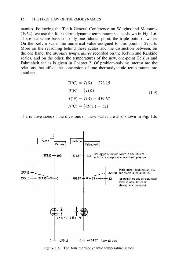
namics. Following the Tenth General Conference on Weights and Measures(1954), we use the four thermodynamic temperature scales shown in Fig. 1.6.These scales are based on only one fiducial point, the triple point of water:On the Kelvin scale, the numerical value assigned to this point is 273.16.More on the reasoning behind these scales and the distinction between, onthe one hand, the absolute temperatures recorded on the Kelvin and Rankinescales, and on the other, the temperatures of the new, one-point Celsius andFahrenheit scales is given in Chapter 2. Of problem-solving interest are therelations that effect the conversion of one thermodynamic temperature intoanother:
T(�C) � T(K) � 273.159–T(R) � T(K)5 (1.9)
T(�F) � T(R) � 459.675–T(�C) � [T(�F) � 32]9
The relative sizes of the divisions of these scales are also shown in Fig. 1.6:

ENERGY CHANGE 17
5–1 R or 1�F � (1 K or 1�C) (1.10)9
Returning now to the concept of heat interaction, the method ofengineering thermodynamics relies on two additional words, adiabatic anddiathermal, that effectively do away with the concept of time and, conse-quently, build a wall between thermodynamics and heat transfer. The wordadiabatic† describes the boundary for which
Q � 0 (1.11)
regardless of the magnitude of the temperature gradient in the direction nor-mal to the boundary. This concept was introduced by Laplace in caloric theory[6, p. 61; however, in engineering thermodynamics, it was made popular byRankine’s book [21] and the creative use of adiabatic lines in the graphicdescription of steam-engine cycles. The second word, diathermal,‡ refers toa boundary across which the temperature gradient is zero even in the presenceof heat transfer. If n is the direction normal to the boundary, for a diathermalboundary we can write
�T� 0 (1.12)
�n
The adiabatic boundary model does not invalidate the boundary definitionrule discussed in connection with Fig. 1.2: The temperature varies continu-ously across the boundary surface; however, the thermal conductivity of thelocal material is so low, or the time of observation is so short, that Q � 0 isa very good approximation of the energy transferred as heat across the bound-ary.
To model a boundary as adiabatic or diathermal means to compare the timescale of the process executed by the system with the time that elapses if thesystem and its environment are allowed to reach thermal equilibrium. If theprocess time scale is considerably shorter than the time to thermal equilib-rium, the boundary can be modeled as adiabatic. In the opposite extreme, theboundary approaches the diathermal model.
1.5 ENERGY CHANGE
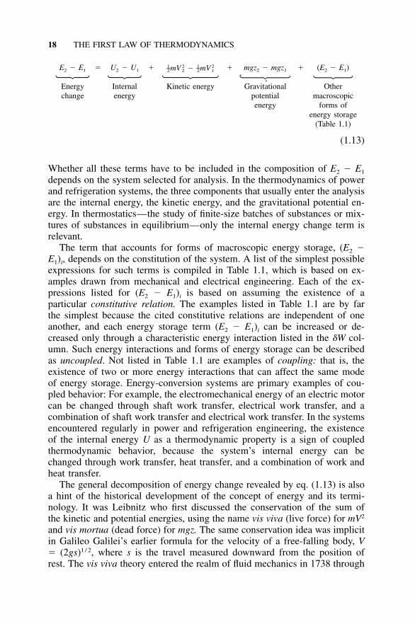
The right side of eq. (1.1) is shorthand for a general expression whose termsdistinguish between macroscopically identifiable forms of energy storage andthe form that cannot be identified macroscopically (which for this reason iscalled internal energy):
† From the Greek word adiabatos (not to be passed; impossible to pass).‡ From the Greek words dia (through) and therme (hot), or thermotis (heat).
18 THE FIRST LAW OF THERMODYNAMICS
E2 � E1 � U2 � U1 � �1 2 1 2– –mV mV2 2 2 1 � mgz2 � mgz1 � (E2 � E1)
Energychange
Internalenergy
Kinetic energy Gravitationalpotentialenergy
Othermacroscopic
forms ofenergy storage
(Table 1.1)
(1.13)
Whether all these terms have to be included in the composition of E2 � E1
depends on the system selected for analysis. In the thermodynamics of powerand refrigeration systems, the three components that usually enter the analysisare the internal energy, the kinetic energy, and the gravitational potential en-ergy. In thermostatics—the study of finite-size batches of substances or mix-tures of substances in equilibrium—only the internal energy change term isrelevant.
The term that accounts for forms of macroscopic energy storage, (E2 �E1)i, depends on the constitution of the system. A list of the simplest possibleexpressions for such terms is compiled in Table 1.1, which is based on ex-amples drawn from mechanical and electrical engineering. Each of the ex-pressions listed for (E2 � E1)i is based on assuming the existence of aparticular constitutive relation. The examples listed in Table 1.1 are by farthe simplest because the cited constitutive relations are independent of oneanother, and each energy storage term (E2 � E1)i can be increased or de-creased only through a characteristic energy interaction listed in the �W col-umn. Such energy interactions and forms of energy storage can be describedas uncoupled. Not listed in Table 1.1 are examples of coupling: that is, theexistence of two or more energy interactions that can affect the same modeof energy storage. Energy-conversion systems are primary examples of cou-pled behavior: For example, the electromechanical energy of an electric motorcan be changed through shaft work transfer, electrical work transfer, and acombination of shaft work transfer and electrical work transfer. In the systemsencountered regularly in power and refrigeration engineering, the existenceof the internal energy U as a thermodynamic property is a sign of coupledthermodynamic behavior, because the system’s internal energy can bechanged through work transfer, heat transfer, and a combination of work andheat transfer.
The general decomposition of energy change revealed by eq. (1.13) is alsoa hint of the historical development of the concept of energy and its termi-nology. It was Leibnitz who first discussed the conservation of the sum ofthe kinetic and potential energies, using the name vis viva (live force) for mV2
and vis mortua (dead force) for mgz. The same conservation idea was implicitin Galileo Galilei’s earlier formula for the velocity of a free-falling body, V� (2gs)1 / 2, where s is the travel measured downward from the position ofrest. The vis viva theory entered the realm of fluid mechanics in 1738 through

ENERGY CHANGE 19
Daniel Bernoulli’s famous treatise on hydrodynamics [22] and in an isolatedearlier instance, through Torricelli’s 1644 formula for the discharge velocityof a fluid driven by its own weight through an orifice. The internal energyterm and the symbol U come from Clausius [16,23] and Rankine [21], al-though the terms inner work, internal work, and intrinsic energy were alsoused by their engineering contemporaries (e.g., Zeuner [17]). The term energy,which in thermodynamics was proposed by William Thomson in 1852, hadbeen coined in 1807 by Thomas Young, the discoverer of the phenomenonof optical interference [24]. Additional highlights of the history of first-lawconcepts are given in Table 1.2 and in the closing sections of this chapter.
Example 1.1. Consider a rigid and evacuated container (bottle) of volume Vthat is surrounded by the atmosphere (T0, P0). At some point in time, the neckvalve of the bottle opens, and atmospheric air gradually flows in. The wall of thebottle is thin and conductive enough so that the trapped air and the atmosphereeventually reach thermal equilibrium. In the end, the trapped air and the atmosphereare also in mechanical equilibrium, because the neck valve remains open.
Determine the net heat interaction that takes place through the wall of the bottleduring the entire filling process. The challenge consists of solving the problem usingthe first-law statement for closed systems [eq. (1.1)]. As the closed system in thisexample, we identify the total airmass that eventually rests inside the bottle:
P V0m � (a)RT0
The final state of the system is represented by the properties (T0, P0, V). Next, wevisualize the position of the airmass m in the beginning of the process: That massresides outside the bottle, and its temperature and pressure are atmospheric. Usingeq. (a) and the PV � mRT equation of state, we learn that the original volumeoccupied by m outside the bottle is also equal to V.
Using 1 and 2 for the beginning and the end of the process by which the closedsystem m moves inside the bottle, the first law provides the equation with whichto calculate the unknown Q1–2:
Q � W � U � U (b)1–2 1–2 2 1
Since we are treating the airmass as an ideal gas in which T1 � T2 � T0, we notethat U2 � U1 � mcv(T2 � T1) � 0; that is,
Q � W (c)1–2 1–2
Finally, we calculate the work interaction by noting that two portions of theboundary of system m move during the process: first, the interface between m andthe rest of the atmosphere, and second, the interface between m and the evacuatedspace. The pressure along these two surfaces are P0 and 0, respectively, whichmeans that work transfer is associated only with the movement of the first interface:
20 THE FIRST LAW OF THERMODYNAMICS
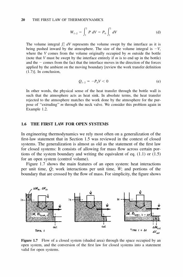
Figure 1.7 Flow of a closed system (shaded area) through the space occupied by anopen system, and the conversion of the first law for closed systems into a statementvalid for open systems.
2 2
W � � P dV � P � dV (d)1–2 01 1
The volume integral dV represents the volume swept by the interface as it is2�1
being pushed inward by the atmosphere. The size of the volume integral is �V,where the V comes from the volume originally occupied by m outside the bottle(note that V must be swept by the interface entirely if m is to end up in the bottle)and the � comes from the fact that the interface moves in the direction of the forcesapplied by the ambient on the moving boundary [review the work transfer definition(1.7)]. In conclusion,
Q � �P V � 0 (e)1–2 0
In other words, the physical sense of the heat transfer through the bottle wall issuch that the atmosphere acts as heat sink. In absolute terms, the heat transferrejected to the atmosphere matches the work done by the atmosphere for the pur-pose of ‘‘extruding’’ m through the neck valve. We consider this problem again inExample 1.2.
1.6 THE FIRST LAW FOR OPEN SYSTEMS
In engineering thermodynamics we rely most often on a generalization of thefirst-law statement that in Section 1.5 was reviewed in the context of closedsystems. The generalization is almost as old as the statement of the first lawfor closed systems: It consists of allowing for mass flow across certain por-tions of the system boundary and writing the equivalent of eq. (1.1) or (1.5)for an open system (control volume).
Figure 1.7 shows the main features of an open system: heat interactionsper unit time, Q; work interactions per unit time, W; and portions of theboundary that are crossed by the flow of mass. For simplicity, the figure shows

THE FIRST LAW FOR OPEN SYSTEMS 21
only one of each type of boundary crossing, one inlet port labeled ‘‘in,’’ andone outlet port labeled ‘‘out.’’ The open system, or the control volume, is theregion contained between the inlet and outlet ports; in other words, the sta-tionary dashed lines labeled ‘‘in’’ and ‘‘out’’ belong to the boundary of theopen system. The work transfer rate W refers to any mode or combination ofwork modes, P dV /dt, Wsh, Welectrical, Wmagnetic, and so on.
Since the first-law statement (1.1) applies strictly to closed systems, weseek a system with a fixed mass inventory that is related to the open systemof interest. If Mopen is the mass inventory of the open system at a certain pointin time t, we can think of the fixed mass inventory Mclosed that at time t‘‘flows’’ through the control volume. According to Fig. 1.7, the relationshipbetween Mopen and Mclosed is
M (constant) � M � M � M � M (1.14)closed open,t in open,(t�t) out
For the process from state 1 (time t) to state 2 (time t � t) executed by theclosed system, the First Law of Thermodynamics (1.1) reads
˙ ˙E � E � Q t � W t � (P V) � (P V) (1.15)closed,(t�t) closed,t in out
The last two terms on the right side account for the P dV type of work transferassociated with the deformation of the closed system from time t to time t �t. Note that in each term, P is the local pressure: that is, the pressure in theimmediate vicinity of the port. Relations similar to eqs. (1.14) express therelative size of the energy inventories of the closed and open systems:
E � E � E (1.16)closed,t open,t in
E � E � E (1.17)closed,(t�t) open,(t�t) out
Furthermore, the E’s and V’s can be rewritten in terms of their per-unit-mass counterparts e and v as
(E) � (e M) and (V) � (v M) (1.18)in,out in,out in,out in,out
Like the port pressure P, the specific energy and volume (e and v, respec-tively) are properties of the intensive state of the fluid that crosses the bound-ary at time t. Combining eqs. (1.15)–(1.17) for the purpose of eliminating theterms that refer to the energy inventory of the closed system (Eclosed), weobtain
1 M M˙ ˙(E � E ) � Q � W � (e � Pv) � (e � Pv)� � � �open,(t�t) open,tt t tin out
(1.19)

22 THE FIRST LAW OF THERMODYNAMICS
Invoking the limit t→0, writing m for the mass flow rate M /t, droppingthe subscript ‘‘open’’ from the energy inventory of the control volume, andassuming that more than one inlet port and outlet port exist, we arrive at themost general statement of the First Law of Thermodynamics for an opensystem:
dE ˙ ˙� Q � W � m(e � Pv) � m(e � Pv) (1.20)� �dt in out
What makes this statement more general than the per-unit-time first lawfor closed systems [eq. (1.5)], are the terms m(e � Pv): These terms representthe energy transfer associated with the flow of mass across the system bound-ary. Finally, in the absence of macroscopic forms of energy storage other thankinetic and gravitational, the specific energy e can be decomposed into (u �V2 � gz) [eq. (1.13)]. The result of this decomposition is that the specific1–2
enthalpy
h � u � Pv (1.21)
shows up explicitly in the terms accounting for energy transfer via mass flow:
dE 1 2 1 2˙ ˙ – –� Q � W � m(h � V � gz) � m(h � V � gz) (1.22)� �2 2dt in out
In the fields of gas dynamics and compressible fluid mechanics, the group (h� V2) is recognized as the local stagnation enthalpy of the flowing fluid.1–2Kestin proposed an engineering generalization of the enthalpy concept underthe name methalpy (symbol h�) [25, p. 223]:
1 2–h� � e � Pv � h � V � gz (1.23)2
which is intended to mean ‘‘beyond enthalpy’’ or ‘‘transcending enthalpy’’[note the Greek word meta (beyond)].
Following a procedure that is analogous to the transformation from closedsystem to open system illustrated in Fig. 1.7, the first-law statement (1.22)can be generalized further by considering the class of open systems wherethe inflows and the outflows are not restricted to penetrating discrete patches(ports) on the control surface. If is the closed control surface that containsAAA
the control volume , the First Law of Thermodynamics readsVVV
�(e) ˙� dVVV � � � q � n dAAA � W � � h�v � n dAAA (1.24)VVV AAA AAA�t
In this expression, q and v represent the heat-flux vector and the velocityvector, respectively, at the points that make up the control surface. The unit

THE FIRST LAW FOR OPEN SYSTEMS 23
vector n is normal to the control surface and points outward. The specificenergy e and methalpy h� are local properties of the material that residesinside the volume element d and along the area element d .VVV AAA
The first-law statement for a control volume of point size situated insideis obtained by transforming the surface integrals of eq. (1.24) into volumeVVV
integrals via the divergence theorem:
�(e) � �� � q � � � (h�v) � w� (1.25)
�t
Or, using the mass-continuity statement shown later [eq. (1.29)], we obtain
�e � v � �e � �� � q � � � (Pv) � w� (1.26)
�t
In these expressions, w� represents the contribution made by the point-sizesystem to the overall work transfer rate W delivered by the finite-size controlvolume in other words, W � w� d (note the definition of positive W)VVV � VVVVVV
(Fig. 1.3). In the continua studied in the field of conduction heat transfer, w�usually accounts for the negative of the volumetric rate of electrical powerdissipation q� [26]. In the fluid media encountered in convective heat transfer,w� accounts for both �q� and the negative of the work done via viscousforces on the point-size control volume [1].
The t→0 limit can be invoked in connection with the second of eqs. (1.14)to yield the mass-conservation statement:
dM� m � m (1.27)� �
dt in out
This equation spells out the difference between open systems and closedsystems (in the latter, the m values are all zero and the mass inventory M isa constant). In the language of eq. (1.24)—that is, for a control volume VVV
enclosed by a permeable control surface —the mass-conservation equationAAA
is
�� dVVV � � � v � n dAAA (1.28)VVV AAA�t
The corresponding statement for a control volume of point size is
D� �� � v (1.29)
Dt
Important in engineering applications is a special class of open systemswhose inventories of mass (M), energy (E), and entropy (S), (Chapter 2) are
24 THE FIRST LAW OF THERMODYNAMICS
time independent. Such systems are said to operate in the steady-state orstationary regime. The equations that govern their operation are simpler be-cause time derivatives such as dE /dt and dM /dt in eqs. (1.22) and (1.27)vanish. The constancy of the M, E, and S inventories in time does not meanthat the mass, energy, and entropy are distributed uniformly through the spaceoccupied by the open system. The steady state should not be confused withthe spatial uniformity of the intensive state.
The First Law of Thermodynamics for open systems and its enthalpy-basedpresentation illustrate admirably the aging of engineering thermodynamicsinto a discipline that threatens to lose sight of its origins. The first law foropen systems was first formulated by Gustav Zeuner as part of the analysisof flow systems that operate in the steady state. He made this result knownprimarily through his technical thermodynamics treatise, whose first Germanedition was published in 1859 [17, pp. 225–231]. Equally impressive is thatZeuner saw and stressed the important role played by the first law in fluidmechanics next to the other equations that in his time were recognized as thepillars of fluid and gas dynamics [27]. Zeuner’s name never made it into fluidmechanics vocabulary; more surprising is that it disappeared from engineeringthermodynamics beginning with the turn of the century.† The most recentreference I can find in connection with ‘‘Zeuner’s formula’’ is in Stodola’streatise on steam turbines, first published in German in 1903 [28]. Zeuner’sstatement of the first law for steady flow and the argument on which itsderivation was based are present in virtually every engineering thermodynam-ics treatise of the twentieth century.
Another example of death and forgetting in the world of engineering ther-modynamics is the invention of the word enthalpy. The widespread use ofthis term was triggered by the work of another professor from the old Uni-versity of Dresden, Richard Mollier (the other influential Dresden figure hadbeen Gustav Zeuner). Mollier recognized the importance of the group u �Pv in the first-law analysis of steam turbines, next to entropy (s) in second-law analysis. He presented graphically and in tabular form the properties of
† About the forget-first-the-engineer syndrome, Rankine wrote in 1859:
. . . the improvers of the mechanical arts were neglected by biographers and historians, froma mistaken prejudice against practice, as being inferior in dignity to contemplation; and evenin the case of men such as Archytas [an ancient Greek philosopher] and Archimedes, whocombined practical skill with scientific knowledge, the records of their labours that havereached our time give but vague and imperfect accounts of their mechanical inventions, whichare treated as matters of trifling importance in comparison with their philosophical specula-tions. The same prejudice, prevailing with increased strength during the middle ages, andaided by the prevalence of the belief in sorcery, rendered the records of the progress of practicalmechanics, until the end of the fifteenth century, almost a blank. Those remarks apply, withpeculiar force, to the history of those machines called PRIME MOVERS . . .. [21, p. xv]
Which is why Rankine—the engineer and cofounder of classical thermodynamics (next to Clau-sius and Kelvin)—is almost never mentioned by the philosophers.

THE FIRST LAW FOR OPEN SYSTEMS 25
steam as the now famous enthalpy–entropy chart (the Mollier chart, h–s) [29].Mollier referred to the group u � Pv as ‘‘heat contents’’ and ‘‘total heat’’ andlabeled it ‘‘i.’’ The symbol i was used until about 40 years ago in the engi-neering thermodynamics taught in German, Russian, and the languages ofCentral and Eastern Europe. Mollier’s contribution is not the discovery of thegroup u � Pv—this group was already known as Gibbs’ ‘‘heat function forconstant pressure’’ (symbol ) [14, p. 92]—rather, it is the invention of animportant graphical tool whose impact on the efficiency of slide-rule calcu-lations in thermal design is beyond question. The term enthalpy† was coinedby Kamerlingh-Onnes [30], professor at the University of Leiden, otherwisefamous for having been the first to liquefy helium and to discover the phe-nomena of superconductivity and superfluidity. Part of the mystery that per-sists in the wake of Kamerlingh-Onnes’ innovations is due to the limitedcirculation enjoyed by his original writings, for which he used Dutch as lan-guage and the bulletin of his own low-temperature laboratory as journal [31].
Example 1.2. Consider again the problem stated in Example 1.1, this time inthe context of open systems: This phenomenon is the common ‘‘filling’’ process.The object is to determine the heat interaction that occurs across the bottle wallduring the filling process.
As open system, we choose the space contained by the bottle. The system hasone inlet port (the neck valve), and the operation of the system is unsteady (thesystem accumulates mass during the process). The mass-conservation equation andthe first law require at any instant that
dM� m (a)
dt
dU ˙� Q � mh (b)0dt
where M and U are the instantaneous inventories of mass and internal energy ofthe system. Symbols Q, m, and h0 stand for the instantaneous heat transfer rate intothe system, the instantaneous inlet flow rate, and the enthalpy of atmospheric air,h0(T0, P0) � constant. The unknown is the integral
2
˙Q � � Q dt (c)1–21
where 1 and 2 denote the start and finish of the filling operation, respectively.Combining eqs. (a)–(c), it is easy to show that
Q � U � U � h (M � M ) (d)1–2 2 1 0 2 1
† Accent on the second syllable; from the Greek word enthalpein (to heat).

26 THE FIRST LAW OF THERMODYNAMICS
or since the open system is initially evacuated (U1 � 0, M1 � 0),
Q � U � M h (e)1–2 2 2 0
Finally, we note that U2 � M2u0, where u0 is the specific internal energy of air atT0 and P0 (recall that T2 � T0 and P2 � P0). Combining eq. (e) with the definitionof enthalpy, we obtain
h � u � P v (f)0 0 0 0
and noting that V � M2v0, we arrive at the same answer as in Example 1.1:
Q � �P M v � � P V (g)1–2 0 2 0 0
Comparing the two methods of deriving this answer, my impression is that theopen-system analysis of Example 1.2 is more direct. However, the closed-systemapproach used in Example 1.1 reveals not only the size and sign of Q1–2, but alsothe physical meaning of the expression P0V. We discuss this physical meaning againin Example 2.2.
The combined message of Examples 1.1 and 1.2 is that there is more thanone way in which to pursue the solution to a given problem. The researcheris free to choose the method [1, p. 53].
1.7 HISTORICAL BACKGROUND
The review presented so far emphasized the main concepts associated withthe first law and those items that are most likely to lead to confusion in theprocess of analyzing an engineering problem. I was unable to discuss thesepoints without drawing attention to their historical background: I believe thatthe effort to understand the pioneers (their personality, research methodology,fights, victories, and disappointments en route to ‘‘making it’’) deserves em-phasis. If we are to speak exotic words such as energy, enthalpy, and entropy,the best teachers of this language can only be its inventors.
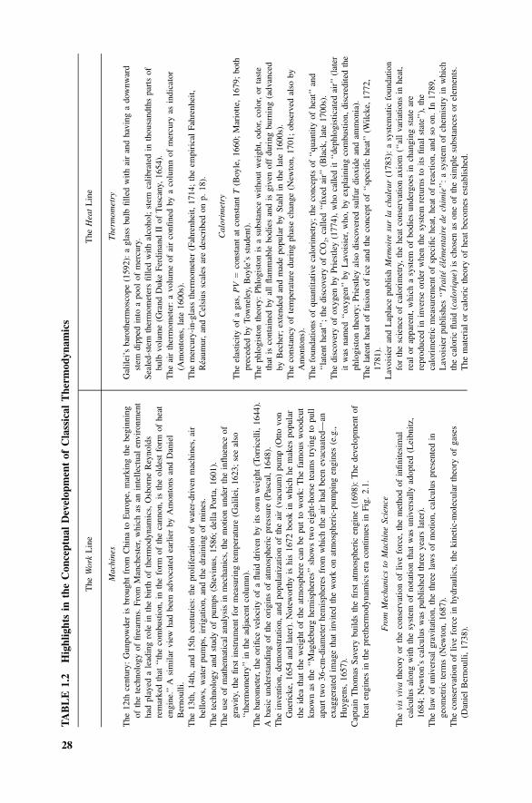
We develop a better understanding of the meaning of the first law bylooking at its position against the development of engineering science in gen-eral. A number of highlights are presented in Table 1.2 by recording first anew concept or discovery, the person responsible for it, and the time frame(usually, the year of publication of the innovator’s main opus). The historicrecord is so vast that any condensation of the type exhibited here reflects firstthe writer’s bias and incomplete knowledge of history. In the present display,an engineering bias was used intentionally to organize these events in twocolumns (or ‘‘currents’’) whose confluence is marked by the emergence ofthermodynamics in the mid-1800s.

HISTORICAL BACKGROUND 27
On the practical side, the ‘‘work’’ line refers to human preoccupation with(1) mechanisms that transmit the mechanical power derived from animal,hydraulic, aeolian, or combustible origins, and (2) machines that producemechanical power while consuming fuel (atmospheric-pumping engines,steam engines). On the practical side of the preoccupation with hotness (the‘‘heat’’ line), (Table 1.2), we recall the measurement of temperature, quantityof heat, and in more recent times the rate of heat propagation (heat transfer).
One practical contribution of the ‘‘heat’’ line was the recording of thechanges undergone by various substances under the influence of heating andcooling: for example, the dilation of thermometric fluids and ‘‘permanentgases.’’ Through such experiments, it was discovered that the state of a batchis determined by two independent properties in addition to the mass of thebatch that was being studied. It is this early work that provides the empiricalfoundation for what we now call state principle and for the analytical andtabular summaries known as equations of state (Chapter 4).
The confluence of the ‘‘work’’ and ‘‘heat’’ lines was accompanied on atheoretical level by the coexistence of two views on the nature of hotness:(1) the mechanical theory, holding that heat is the manifestation of motion(live force) at the molecular level, and (2) the material or caloric theory,maintaining that the caloric fluid contained in a substance is uniquely definedif the state is specified. A key word in describing the evolution of these twoviews is coexistence, which means that the mechanical and caloric theorieswere not mutually exclusive and that they were accepted together as comple-mentary. Note that the success and wide acceptance of the newer theory (thecaloric theory) was the result of the great service that this theory rendered tothe quantitative fields of thermochemistry and ‘‘heat engineering.’’
No theory is perfect and forever. One respect in which the caloric theoryfailed—the generation of heat through friction—was well known in the 1700sand was certainly known by Lavoisier and Laplace. This particular limitationof the caloric theory was assaulted in a series of papers started in 1798 byCount Rumford [32,33] based on exhaustive and otherwise approximate ob-servations of the heat generated by a drill during the boring of a cannon.†
† Count Rumford’s 1798 paper begins with advice to all researchers to keep their eyes open:
It frequently happens, that in the ordinary affairs and occupations of life, opportunities presentthemselves of contemplating some of the most curious operations of nature; and very inter-esting philosophical experiments might often be made, almost without trouble or expence, bymeans of machinery contrived for the mere mechanical purposes of the arts and manufacturer.
I have frequently had occasion to make this observation; and am persuaded, that a habit ofkeeping the eyes open to every thing that is going on in the ordinary course of the businessof life has oftener led, as it were by accident, or in the playful excursions of the imagination,put into action by contemplating the most common appearances, to useful doubts and sensibleschemes for investigating and improvement, than all the more intense meditations of philos-ophers, in the hours expressly set apart for study. [32, p. 80] (continued on p. 30)
28
TA
BL
E1.
2H
ighl
ight
sin
the
Con
cept
ual
Dev
elop
men
tof
Cla
ssic
alT
herm
odyn
amic
s
The
Wor
kL
ine
The
Hea
tL
ine
Mac
hine
s
The
12th
cent
ury:
Gun
pow
der
isbr
ough
tfr
omC
hina
toE
urop
e,m
arki
ngth
ebe
ginn
ing
ofth
ete
chno
logy
offir
earm
s.Fr
omM
anch
este
r,w
hich
asan
inte
llect
ual
envi
ronm
ent
had
play
eda
lead
ing
role
inth
ebi
rth
ofth
erm
odyn
amic
s,O
sbor
neR
eyno
lds
rem
arke
dth
at‘‘
the
com
bust
ion,
inth
efo
rmof
the
cann
on,
isth
eol
dest
form
ofhe
aten
gine
.’’A
sim
ilar
view
had
been
advo
cate
dea
rlie
rby
Am
onto
nsan
dD
anie
lB
erno
ulli.
The
13th
,14
th,
and
15th
cent
urie
s:th
epr
olif
erat
ion
ofw
ater
-dri
ven
mac
hine
s,ai
rbe
llow
s,w
ater
pum
ps,
irri
gatio
n,an
dth
edr
aini
ngof
min
es.
The
tech
nolo
gyan
dst
udy
ofpu
mps
(Ste
vinu
s,15
86;
della
Port
a,16
01).
The
use
ofm
athe
mat
ical
anal
ysis
inm
echa
nics
,th
em
otio
nun
der
the
influ
ence
ofgr
avity
,th
efir
stin
stru
men
tfo
rm
easu
ring
tem
pera
ture
(Gal
ilei,
1623
;se
eal
so‘‘
ther
mom
etry
’’in
the
adja
cent
colu
mn)
.T
heba
rom
eter
,th
eor
ifice
velo
city
ofa
fluid
driv
enby
itsow
nw
eigh
t(T
orri
celli
,16
44).
Aba
sic
unde
rsta
ndin
gof
the
orig
ins
ofat
mos
pher
icpr
essu
re(P
asca
l,16
48).
The
inve
ntio
n,de
mon
stra
tion,
and
popu
lari
zatio
nof
the
air
(vac
uum
)pu
mp
(Otto
von
Gue
rick
e,16
54an
dla
ter)
.N
otew
orth
yis
his
1672
book
inw
hich
hem
akes
popu
lar
the
idea
that
the
wei
ght
ofth
eat
mos
pher
eca
nbe
put
tow
ork:
The
fam
ous
woo
dcut
know
nas
the
‘‘M
agde
burg
hem
isph
eres
’’sh
ows
two
eigh
t-ho
rse
team
str
ying
topu
llap
art
two
36-c
m-d
iam
eter
hem
isph
eres
from
whi
chth
eai
rha
dbe
enev
acua
ted—
anex
agge
rate
dim
age
that
invi
ted
the
wor
kon
atm
osph
eric
-pum
ping
engi
nes
(e.g
.,H
uyge
ns,
1657
).C
apta
inT
hom
asSa
very
build
sth
efir
stat
mos
pher
icen
gine
(169
8):
The
deve
lopm
ent
ofhe
aten
gine
sin
the
pret
herm
odyn
amic
ser
aco
ntin
ues
inFi
g.2.
1.
Fro
mM
echa
nics
toM
achi
neSc
ienc
e
The
vis
viva
theo
ryor
the
cons
erva
tion
ofliv
efo
rce,
the
met
hod
ofin
finite
sim
alca
lcul
usal
ong
with
the
syst
emof
nota
tion
that
was
univ
ersa
llyad
opte
d(L
eibn
itz,
1684
;N
ewto
n’s
calc
ulus
was
publ
ishe
dth
ree
year
sla
ter)
.T
hela
wof
univ
ersa
lgr
avita
tion,
the
thre
ela
ws
ofm
otio
n,ca
lcul
uspr
esen
ted
inge
omet
ric
term
s(N
ewto
n,16
87).
The
cons
erva
tion
ofliv
efo
rce
inhy
drau
lics,
the
kine
tic-m
olec
ular
theo
ryof
gase
s(D
anie
lB
erno
ulli,
1738
).
The
rmom
etry
Gal
ilei’
sba
roth
erm
osco
pe(1
592)
:a
glas
sbu
lbfil
led
with
air
and
havi
nga
dow
nwar
dst
emdi
pped
into
apo
olof
mer
cury
.Se
aled
-ste
mth
erm
omet
ers
fille
dw
ithal
coho
l;st
emca
libra
ted
inth
ousa
ndth
spa
rts
ofbu
lbvo
lum
e(G
rand
Duk
eFe
rdin
and
IIof
Tus
cany
,16
54).
The
air
ther
mom
eter
:a
volu
me
ofai
rco
nfine
dby
aco
lum
nof
mer
cury
asin
dica
tor
(Am
onto
ns,
late
1600
s).
The
mer
cury
-in-
glas
sth
erm
omet
er(F
ahre
nhei
t,17
14;
the
empi
rica
lFa
hren
heit,
Rea
umur
,an
dC
elsi
ussc
ales
are
desc
ribe
don
p.18
).
Cal
orim
etry
The
elas
ticity
ofa
gas,
PV
�co
nsta
ntat
cons
tant
T(B
oyle
,16
60;
Mar
iotte
,16
79;
both
prec
eded
byTo
wne
ley,
Boy
le’s
stud
ent)
.T
heph
logi
ston
theo
ry:
Phlo
gist
onis
asu
bsta
nce
with
out
wei
ght,
odor
,co
lor,
orta
ste
that
isco
ntai
ned
byal
lfla
mm
able
bodi
esan
dis
give
nof
fdu
ring
burn
ing
(adv
ance
dby
Bec
her;
exte
nded
and
mad
epo
pula
rby
Stah
lin
the
late
1600
s).
The
cons
tanc
yof
tem
pera
ture
duri
ngph
ase
chan
ge(N
ewto
n,17
01;
obse
rved
also
byA
mon
tons
).T
hefo
unda
tions
ofqu
antit
ativ
eca
lori
met
ry;
the
conc
epts
of‘‘
quan
tity
ofhe
at’’
and
‘‘la
tent
heat
’’;
the
disc
over
yof
CO
2,
calle
d‘‘
fixed
air’
’(B
lack
,la
te17
00s)
.T
hedi
scov
ery
ofox
ygen
byPr
iest
ley
(177
4),
who
calle
dit
‘‘de
phlo
gist
icat
edai
r’’
(lat
erit
was
nam
ed‘‘
oxyg
en’’
byL
avoi
sier
,w
ho,
byex
plai
ning
com
bust
ion,
disc
redi
ted
the
phlo
gist
onth
eory
;Pr
iest
ley
also
disc
over
edsu
lfur
diox
ide
and
amm
onia
).T
hela
tent
heat
offu
sion
ofic
ean
dth
eco
ncep
tof
‘‘sp
ecifi
che
at’’
(Wilc
ke,
1772
,17
81).
Lav
oisi
eran
dL
apla
cepu
blis
hM
emoi
resu
rla
chal
eur
(178
3):
asy
stem
atic
foun
datio
nfo
rth
esc
ienc
eof
calo
rim
etry
,th
ehe
atco
nser
vatio
nax
iom
(‘‘a
llva
riat
ions
inhe
at,
real
orap
pare
nt,
whi
cha
syst
emof
bodi
esun
derg
oes
inch
angi
ngst
ate
are
repr
oduc
edin
inve
rse
orde
rw
hen
the
syst
emre
turn
sto
itsfin
alst
ate’
’),
the
calo
rim
etri
cm
easu
rem
ent
ofsp
ecifi
che
at,
heat
ofre
actio
n,an
dso
on.
In17
89,
Lav
oisi
erpu
blis
hes
‘‘Tr
aite
elem
enta
ire
dech
imie
’’:
asy
stem
ofch
emis
try
inw
hich
the
calo
ric
fluid
(cal
oriq
ue)
isch
osen
ason
eof
the
sim
ple
subs
tanc
esor
elem
ents
.T
hem
ater
ial
orca
lori
cth
eory
ofhe
atbe
com
eses
tabl
ishe
d.

29
The
mat
hem
atic
alfo
unda
tions
ofin
visc
idflu
idflo
w(E
uler
,17
55).
The
grav
itatio
nal
field
theo
ry,
the
mat
hem
atic
sof
ther
mal
diff
usio
n(L
apla
ce,
1785
and
late
r).
The
law
gove
rnin
gfr
ictio
n(C
oulo
mb,
ina
1781
priz
e-w
inni
ngpa
per)
.T
heeq
uatio
nsof
anal
ytic
alm
echa
nics
(Lag
rang
e,17
88).
The
foun
datio
nsof
desc
ript
ive
geom
etry
(Mon
ge,
1795
).T
hebe
ginn
ings
ofa
scie
nce
ofm
achi
nes
(mec
hani
sms)
;th
e‘‘
Car
not
prin
cipl
e’’
ofav
oidi
ngsh
ocks
,pe
rcus
sion
,an
dtu
rbul
ent
flow
inor
der
toac
hiev
em
axim
umef
ficie
ncy
orco
ntin
uity
inth
etr
ansm
issi
onof
mec
hani
cal
pow
er(L
azar
eC
arno
t,17
83;
heal
sode
fines
the
conc
ept
of‘‘
mom
ent
ofac
tivity
,’’w
hich
in18
29w
asna
med
‘‘w
ork,
’’in
depe
nden
tlyby
Cor
iolis
and
Ponc
elet
).T
heE
cole
Poly
tech
niqu
eis
esta
blis
hed
in17
95:
unde
rits
influ
ence
and
thro
ugh
the
teac
hing
sof
som
eof
itsfir
stgr
adua
tes,
the
stud
yof
mac
hine
sbe
com
esce
ntra
lto
engi
neer
ing
educ
atio
nev
eryw
here
(e.g
.,co
urse
sby
Nav
ier,
1826
;C
orio
lis,
1829
;Po
ncel
et,
1829
).T
he‘‘
dyna
mic
unit’
’or
‘‘dy
nam
ode,
’’as
the
wor
kre
quir
edto
rais
e1
kilo
gram
toa
heig
htof
1m
eter
(Hac
hette
,18
11);
the
‘‘ca
lori
e’’
was
defin
edas
the
quan
tity
ofhe
atre
quir
edto
rais
eth
ete
mpe
ratu
reof
1ki
logr
amof
wat
erby
1 �C
(Cle
men
t,18
26).
The
gas
law
V�
Tat
cons
tant
P(G
ay-L
ussa
c,18
02;
heal
sodi
scov
ered
that
U
�0
atco
nsta
ntT
inga
ses)
.T
hela
wof
part
ial
pres
sure
sin
gas
mix
ture
s(D
alto
n,18
05);
Avo
gadr
o’s
law
(181
1).
The
disc
over
yof
‘‘cr
itica
lte
mpe
ratu
re’’
(Cag
nard
Lat
our,
1810
s).
The
appr
oxim
ate
char
acte
rof
Boy
le’s
law
for
real
gase
s;th
eca
refu
lm
easu
rem
ent
ofth
esp
ecifi
che
atan
dth
erm
alex
pans
ion
coef
ficie
ntof
gase
s,liq
uids
,an
dso
lids
(Reg
naul
t,m
id-1
800s
).
Hea
tTr
ansf
er
The
prop
ortio
nalit
ybe
twee
nco
olin
gra
tean
dbo
dy-s
urro
undi
ngs
tem
pera
ture
diff
eren
ce(N
ewto
n,17
01).
Com
para
tive
mea
sure
men
tof
ther
mal
cond
uctiv
ity(I
ngen
Hou
sz,
1785
,17
89;
Cou
ntR
umfo
rd,
1786
and
late
r).
Con
vect
ion
asa
prin
cipa
lhe
attr
ansf
erm
echa
nism
thro
ugh
clot
hing
(Rum
ford
,17
97;
the
wor
dco
nvec
tion
was
coin
edby
Prou
tin
1834
).T
hepr
opor
tiona
lity
betw
een
heat
tran
sfer
rate
and
tem
pera
ture
grad
ient
(Bio
t,18
04);
also
the
dist
inct
ion
betw
een
the
ther
mal
cond
uctiv
ityan
dth
ehe
attr
ansf
erco
effic
ient
(Fou
rier
,18
07).
Four
ier
form
ulat
esth
epa
rtia
ldi
ffer
entia
leq
uatio
nfo
rtim
e-de
pend
ent
heat
cond
uctio
n(1
807)
:In
toda
y’s
lang
uage
,th
isra
nks
asth
efir
stan
alyt
ical
form
ulat
ion
ofth
efir
stla
w(i
nth
eco
ntex
tof
zero
-wor
kpr
oces
ses,
Tabl
e1.
3).
The
field
ofhe
attr
ansf
erco
ntin
ues
tode
velo
pal
ong
the
pure
‘‘he
at’’
line
into
the
late
1900
s,w
hen
itis
reun
ited
with
the
field
ofen
gine
erin
gth
erm
odyn
amic
sin
1982
[11]
.
The
assa
ult
onth
eco
nser
vatio
nof
calo
ric
doct
rine
(Cou
ntR
umfo
rd,
1798
and
late
r;Si
rH
umph
ryD
avy,
1799
).
The
‘‘he
at’’
equi
vale
ntof
‘‘w
ork,
’’or
,tr
aditi
onal
ly,
the
‘‘m
echa
nica
leq
uiva
lent
ofhe
at’’
(the
theo
retic
allin
e:M
ayer
,18
42an
dla
ter;
also
Segu
in,
1839
;H
oltz
man
n,18
45;
the
expe
rim
enta
llin
e:Jo
ule,
1843
and
late
r;en
rich
edby
Vio
lle,
1870
;R
owla
nd,
1879
;H
irn;
and
othe
rs).
The
‘‘fir
stla
w’’
asan
inte
gral
part
ofth
ene
wsc
ienc
eof
‘‘th
erm
odyn
amic
s’’
(Cla
usiu
s,18
50an
dla
ter;
Ran
kine
,18
50an
dla
ter;
Kel
vin,
1851
and
late
r).

30 THE FIRST LAW OF THERMODYNAMICS
This theme was also advocated by Sir Humphry Davy, who communicatedthat he was able to induce the melting of two blocks of ice by rubbing themagainst each other. Although the correctness of Davy’s communication hasbeen questioned [34], and despite the view expressed by some that Rumfordhad a gift for exaggeration, the vociferous attack on one shortcoming of thecaloric theory played an important role in the developments that were to takeplace in the 1840s and 1850s. The Rumford–Davy theme did not win manyconverts at the turn of the century; however, it was used conveniently andsuccessfully by the founders of thermodynamics (Joule even attributed toRumford the honor of having first measured the heat equivalent of work—this, in order to draw the establishment’s attention to his own measurements[35]).
The Rumford–Davy line of questioning contributed to preparing an audi-ence for the theory that was to arrive. Note Sadi Carnot’s Manuscript Notespapers, which were saved and revealed first in 1871 by Sadi’s brother Hip-polyte and which had probably been written around the time of his 1824memoir [36]. In these notes we find that Sadi Carnot had questioned theconservation of caloric doctrine and decided, ‘‘Heat is nothing more thanmotive power, or, in other words, the motion that has changed form. Wherevermotive force is produced, there is always production of heat in a quantityprecisely proportional to the quantity of motive power destroyed. Conversely:Wherever there is destruction of heat, there is production of motive power.’’He concludes that ‘‘one can state as a general thesis that the motive power isan invariable quantity in nature and that it is never, properly speaking, pro-duced or destroyed. In fact, it changes form; that is, it produces sometimesone kind of motion, sometimes another, but it is never exhausted’’ [18, p. 51;
About the experiment in which water boiled as a result of frictional heating, he wrote:
At 2 hours 20 minutes it was at 200�(F); and at 2 hours 30 minutes it ACTUALLY BOILED!
It would be difficult to describe the surprise and astonishment expressed by the countenancesof the by-standers, on seeing so large a quantity of cold water heated, and actually made toboil, without any fire.
Though there was, in fact, nothing that could justly be considered as surprising in this event,yet I acknowledge fairly that it afforded me a degree of childish pleasure, which, were Iambitious of the reputation of a grave philosopher, I ought most certainly rather to hide thanto discover. [32, p. 92]
His final and famous conclusion on the origin of the observed heating effect was as follows:
It is hardly necessary to add, that any thing which any insulated body, or system of bodies,can continue to furnish without limitation, cannot possibly be a material substance: and itappears to me to be extremely difficult, if not quite impossible, to form any distinct idea ofany thing, capable of being excited, and communicated, in the manner the heat was excitedand communicated in these experiments, except it be MOTION. [32, p. 99]

HISTORICAL BACKGROUND 31
my translation]. After this unambiguous statement of the future principle ofthe conservation of energy (the first law), he reports an estimate of the heatequivalent of one unit of motive power, which today amounts to 3.7 joules/calorie—that is, only 12 percent below the modern value of 4.186 joules/calorie.
Sadi Carnot’s unpublished notes do not in any way detract from the creditthat Mayer and Joule deserve for publishing similar views, and for fightingthe battle to have them accepted. The notes show, however, that Sadi Carnot’sthinking was well ahead of the views expressed in his published memoir and,quite possibly, that the conservation of caloric doctrine was losing groundamong some of his peers. One of these, Emile Clapeyron, wrote in 1834 that‘‘a quantity of mechanical action and a quantity of heat which can pass froma hot body to a cold body are quantities of the same nature, and that it ispossible to replace the one by the other—in the same manner as in mechanicsa body which is able to fall from a certain height and a mass moving with acertain velocity are quantities of the same order, which can be transformedone into the other by physical means’’ [4, pp. 36–51].
The first clear-cut theory expressing that ‘‘heat’’ and ‘‘work’’ are equivalentand that their respective units are convertible was published independently byMayer in May 1842 [37] and Joule in August 1843 [38]. This dual approachto such a great step is a perfect example of how differently two people canthink, and it is a very strong case for free access to the marketplace of ideasas the best recipe for scientific progress. An important item in the history ofthe first law is the fact that both Mayer and Joule had difficulty in gettingtheir papers published and in being taken seriously by their established con-temporaries.
Mayer was the theoretician, the man obsessed by the idea: He conceivedit in circumstances that even today appear removed from the thermodynamicsscene (more on this shortly), and then he relied on the contemporary state ofknowledge to support its validity. Joule, on the other hand, was the ultimateexperimentalist: He first discovered in his measurements that the heat gen-erated by electrical resistances is proportional to the mechanical power re-quired to generate the electrical power. He then recognized the importance ofthis proportionality and drew the revolutionary conclusion that a universalproportionality must exist between the two effects (work and heat). Only topolish this idea and to convince the skeptics (e.g., the Royal Society), heproduced a series of nakedly simple experiments whose message proved im-possible to refute. From the point of view of mechanical engineers, the mostmemorable among these experiments was the heating of a pool of water byan array of paddle wheels driven by falling weights.
Mayer’s entrance on this controversial stage was considerably different. Amedical doctor by training, he was serving as surgeon on a ship sailingthrough the East Indies when he observed that the blood of European sailorsshowed a brighter color of red: that is, a smaller rate of oxidation. This wasin July 1840. He attributed this observation to the high temperatures near
32 THE FIRST LAW OF THERMODYNAMICS
the equator: that is, to the lower metabolic rate that is needed to maintain thebody temperature. Mayer, however, went beyond the connection betweenthe chemical energy contained in food and the rejection of body heat to theambient: He saw the energy of food as the common source of both body heatand muscular work; in other words, he saw intuitively that heat and workhave similar origins and are interconvertible.
It was pointed out by Epstein [39] that the field of physiology had alreadyseen a connection between heat and work in the form of an outmoded theoryof respiration that claimed that body heat is generated by the friction of airin the air passages of the lungs. The theory was being displaced at the timeby Lavoisier’s conclusive theory of oxidation. Epstein’s research of the phys-iology literature and of the healthy intellectual milieu of Manchester (of whichCardwell [7] writes so well) goes on to suggest that the physiologists’ con-nection between heat and work was also known to Joule.†
Mayer was very clear about the meaning of his theory: ‘‘We must find outhow high a particular weight must be raised above the surface of the earth inorder that its falling power may be equivalent to the heating of an equalweight of water from 0� to 1�C’’ [37, p. 240]. He reasoned that an amount ofgas has to be heated more at constant pressure than at constant volume,because at constant pressure it is free to dilate and do work against the at-mosphere; in today’s notation we would write mcP T � mcv T � Patm V,where V is the volume increment associated with T and P � Patm. Usingthe cP and cP /cv constants known in his time, he estimated the left side ofthe equation in calories, while the right side was known in mechanical units.He established the equivalence between these units numerically by listing‘‘365 m’’ as the answer to the question quoted earlier in this paragraph (thisnumber corresponds to 3.58 joules/calorie; that is, it is nearly the same asSadi Carnot’s estimate on p. 31). Worth noting is that if we use Clapeyron’sequation Pv � RT in Mayer’s argument previously, we arrive at ‘‘cP � cv �R’’: This classical relation between the specific heats of an ideal gas is rec-ognized as Mayer’s equation.
Most, if not all, of the credit for convincing the skeptics and putting theheat/work equivalence on the books belongs to Joule, whose experiments
† Revealing is Tisza’s one-sentence dismissal of the suggestion that Joule’s work and ideas mayhave had something to do with physiology and Count Rumford [8, p. 25]: This is just one of themany subtle attempts to banish the thought that the pioneers might have been something otherthan physicists: namely, engineers (Sadi Carnot, Clapeyron, Seguin, Rankine, and the many enginebuilders of Scotland and Cornwall) (Fig. 2.1), medical doctors (Mayer, Helmholtz), public servants(Fourier, Lazare Carnot), and—we should not forget—military men (Lazare and Sadi Carnot,Count Rumford, Helmholtz). The symbol of this diverse group is Joule himself, a man whoreceived no formal education: that is, a veritable amateur.

HISTORICAL BACKGROUND 33
found a strong and very influential supporter in William Thomson.† Mayerreceived recognition for his theoretical contribution later, thanks to the effortsof Tyndall, Helmholtz, and, among engineers, Zeuner. Helmholtz’s letter toTait on behalf of Mayer [41,42] is, in retrospect, an important statement onscientific progress and a discoverer’s troubles with the establishment in gen-eral:
I must say that to me the discoveries of Kirchhoff in this area (radiation andabsorption) appear to be one of the most instructive cases in the history of science,precisely because so many others had previously been so close to making the samediscoveries. Kirchhoff’s predecessors in this field were related to him in roughlythe same way in which, with respect to the conservation of force, Robert Mayer,Colding, and Seguin were related to Joule and William Thomson.
With respect to Robert Mayer, I can, of course, understand the position you havetaken in opposition to him; I cannot, however, let this opportunity pass withoutstating that I am not completely of the same opinion. The progress of the naturalsciences depends always upon new inductions being formed out of available facts,and upon the consequence of these inductions, insofar as they refer to new facts,being compared with reality through the use of experiments. There can be no doubtconcerning the necessity of this second undertaking. This part of science oftenrequires a large amount of work and great ingenuity, and we are obligated in thehighest degree to those who do it well. The fame of discovery, however, remainswith those who have found the new idea; the later experimental verification is quitea mechanical occupation. Further, we cannot demand unconditionally that the per-son who discovers a new idea also be obligated to carry out the second part of thework. If this were the case, we would have to reject the greatest part of the workof all mathematical physicists. William Thomson, for example, produced a numberof theoretical papers concerning Carnot’s law and its consequences before he per-formed a single experiment, and it would not occur to any one of us to treat theselightly.
Robert Mayer was not in a position to conduct experiments; he was repulsed bythe physicists with whom he was acquainted (this also happened to me several
† In a note dated 1885, Joule wrote:
It was in the year 1843 that I read a paper ‘‘On the Calorific Effects of Magneto-Electricityand the Mechanical Value of Heat’’ to the Chemical Section of the British Association assem-bled at Cork. With the exception of some eminent men . . . the subject did not excite muchgeneral attention; so that when I brought it forward again at the meeting in 1847, the chairmansuggested that . . . I should not read my paper, but confine myself to a short verbal descriptionof my experiments. This I endeavoured to do, and discussion not being invited, the commu-nication would have passed without comment if a young man had not risen in the section,and by his intelligent observation created a lively interest in the new theory. The young manwas William Thomson, who had two years previously passed the University of Cambridgewith the highest honour, and is now probably the foremost scientific authority of the age . . ..[40]

34 THE FIRST LAW OF THERMODYNAMICS
years later); it was only with difficulty that he could find space for the publicationof his first condensed formulation of this principle. You must know that as a resultof this rejection he at last became mentally ill. It is now difficult to set oneselfback into the modes of thought of that period, and to make clear to oneself howabsolutely new the whole idea seemed at that time. I should imagine that Joule toomust have fought for a long time in order to gain recognition for his discovery.
Thus, although no one can deny that Joule did much more than Mayer, and althoughone must admit that in the first publications of Mayer there were many things thatwere unclear, still I believe that one must accept that Mayer formulated this idea,which determined the most important recent progress in the natural sciences, in-dependently and completely. His reward should not be lessened because at the sametime another man in another country and under other conditions made the samediscovery and, to be sure, carried it through afterwards better than he did.
1.8 THE STRUCTURED PRESENTATION OF THE FIRST LAW
The objective of this chapter has been to review the various concepts of thefirst law. We end the chapter by reviewing several ways of streamlining andstructuring the presentation of the first law (Table 1.3). Each formulationreveals the same structure, which begins with the selection of the smallestnumber of understandable notions that serve as primary concepts for the re-mainder of the scheme. Additional concepts are later defined using the pri-mary concepts and an appropriate statement of the first law.
1.8.1 Poincare’s Scheme
The first structured presentation of this kind was made by Poincare [18]. Asprimary concepts, he chose the heat transfer, the temperature, and the expe-rience condensed in the Zeroth Law of Thermodynamics. For the definitionof the concept of heat transfer (heat, in the thermodynamics language of thelate 1800s), he relied heavily on the science of calorimetry, which—it is worthnoting—is a science that serves us well to this day despite the celebratedfailure of certain aspects of the caloric theory. Heat transfer was defined asthe system–environment interaction made possible by the inequality of tem-peratures between the two systems. The size of the heat interaction was mea-sured by counting the number of auxiliary standard systems that must beplaced in thermal communication with the system of interest. The functionof the standard system is to undergo a temperature excursion between twostandard temperature levels under the influence of the heat interaction that isto be measured.
As foundation for the first law, Poincare chose the numerous measurementsof the mechanical equivalent of heat pioneered by Joule and continued byRowland, Violle, and Hirn, and then he stated that the work transfer equalsthe heat transfer during a complete cycle. Finally, Poincare defined the dif-
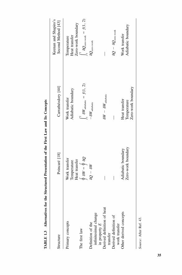
35
TA
BL
E1.
3A
lter
nati
ves
for
the
Stru
ctur
edP
rese
ntat
ion
ofth
eF
irst
Law
and
Its
Con
cept
s
Stru
ctur
ePo
inca
re[1
8]C
arra
theo
dory
[44]
Kee
nan
and
Shap
iro’
sSe
cond
Met
hod
[43]
Prim
ary
conc
epts
Wor
ktr
ansf
erTe
mpe
ratu
reH
eat
tran
sfer
Wor
ktr
ansf
erA
diab
atic
boun
dary
Tem
pera
ture
Hea
ttr
ansf
erZ
ero-
wor
kbo
unda
ryT
hefir
stla
w��
W���
Q2 ��
W�
ƒ(1,
2)ad
iabat
ic1
2 ��Q
�ƒ(
1,2)
zero
-work
1
Defi
nitio
nof
the
infin
itesi
mal
chan
gein
prop
erty
E
�Q
��W
��W
adia
bat
ic�Q
zero
-wo
rk
Der
ived
defin
ition
ofhe
attr
ansf
er—
�W
��W
adia
bat
ic—
Der
ived
defin
ition
ofw
ork
tran
sfer
——
�Q
��Q
zero
-wo
rk
Oth
erde
rive
dco
ncep
tsA
diab
atic
boun
dary
Zer
o-w
ork
boun
dary
Hea
ttr
ansf
erTe
mpe
ratu
reZ
ero-
wor
kbo
unda
ry
Wor
ktr
ansf
erA
diab
atic
boun
dary
Sour
ce:
Aft
erR
ef.
43.

36 THE FIRST LAW OF THERMODYNAMICS
ference between heat transfer and work transfer as a new quantity calledinternal energy, and he relied on the first law to prove that the internal energyis a thermodynamic property.
1.8.2 Caratheodory’s Scheme
The third column of Table 1.3 shows another approach, which relies on theconcepts of work transfer and adiabatic boundary as primary concepts [44].The work transfer is defined by reference to the mechanical concept of work.While avoiding any reference to thermal concepts that would certainly soundmore appealing and natural, the adiabatic wall is defined by the special featurethat the ‘‘equilibrium of a body enclosed by (this wall) is not disturbed byany external process as long as no part of the wall is moved (distance forcesbeing excluded in the whole consideration)’’ [45].
The next step in the Caratheodory structure is the first-law statement thatthe work transfer experienced by a closed system surrounded by an adiabaticboundary depends only on the end states of the process. One consequence ofthis statement is that the adiabatic work transfer is a thermodynamic prop-erty—hence the definition of the property E:
dE � ��W (1.30)adiabatic
Under the Caratheodory scheme, the heat transfer becomes a derived concept,as �Q is defined simply as the sum dE � �W. The temperature also becomesa derived concept: Two bodies are said to have the same temperature whenthe heat transfer �Q (or dE � �W) is zero in the absence of an adiabatic wall.
1.8.3 Keenan and Shapiro’s Second Scheme
Although the Poincare and Caratheodory presentations cover very well therange from the most successful to the most abstract, they do not represent allthe possibilities of introducing the first law and its concepts. Keenan andShapiro [43] proposed two alternate routes, the second of which is summa-rized in the fourth column of Table 1.3. The primary concepts are the tem-perature, the heat transfer, and the zero-work boundary. The temperature andthe heat transfer are defined in the same way as Poincare’s method. Theconcept of zero-work boundary, on the other hand, is an instrument requiredto get to the first law while avoiding any reference to work transfer (note herethe relationship between this idea and Caratheodory’s). In Keenan and Sha-piro’s definition, ‘‘a zero-work wall is a wall which is motionless (except inthe absence of force at the wall) and through which pass no moving forcefields and no electrical currents.’’
The first law amounts to the statement that the heat transfer experiencedby a system surrounded by a zero-work boundary depends only on the end
REFERENCES 37
states of the process. Energy, then, is the name given to this thermodynamicproperty:
dE � �Q (1.31)zero-work
As a derived concept, the work interaction is defined as the difference �Q �dE, or
�W � �Q � �Q (1.32)zero-work
Finally, the adiabatic boundary is the one for which we can write �Q � 0.Keenan and Shapiro’s second scheme draws attention to a very special set
of circumstances in which ‘‘heat’’ is indeed ‘‘conserved’’ [eq. (1.31)]. Thisobservation begs us to look back at what preceded modern thermodynamicsand to appreciate a little more the legitimacy of the caloric theory [46] as amilestone in man’s search for truth and in the development of his language.Of course, no theory is perfect and forever, which is why there is somethingrotten in the contemporary trend of portraying the caloric thinking as theequivalent of ‘‘failure’’ and ‘‘bad thermodynamics.’’ A theory that was createdby the minds of Lavoisier and Laplace—the theory that was misused so cre-atively by Sadi Carnot—couldn’t have been all bad!
REFERENCES
1. A. Bejan, Convection Heat Transfer, Wiley, New York, 1984, 1995, 3rd ed., 2004.2. S. Carnot, Reflections on the Motive Power of Fire, and on Machines Fitted to
Develop That Power, Bachelier, Paris, 1824; also in E. Mendoza, ed., Reflectionson the Motive Power of Fire and Other Papers, Dover, New York, 1960; abbre-viated in Ref. 4.
3. M. Planck, Treatise on Thermodynamics, 3rd ed., translated by A. Ogg, Dover,New York, 1945, p. 40.
4. J. Kestin, ed., The Second Law of Thermodynamics, Pt. I, Dowden, Hutchinson &Ross, Stroudsburg, PA, 1976.
5. C. Truesdell, The Tragicomedy of Classical Thermodynamics, International Centrefor Mechanical Sciences, Udine, Italy, Courses and Lectures, No. 70, Springer-Verlag, Berlin and New York, 1983.
6. C. Truesdell, Rational Thermodynamics, 2nd ed., Springer-Verlag, New York,1984, pp. 1–48.
7. D. S. L. Cardwell, From Watt to Clausius, Cornell University Press, Ithaca, NY,1971.
8. L. Tisza, Generalized Thermodynamics, MIT Press, Cambridge, MA, 1966, pp.5–29.
9. G. N. Hatsopoulos and J. H. Keenan, Principles of General Thermodynamics,Wiley, New York, 1965, pp. XV–XLII.

38 THE FIRST LAW OF THERMODYNAMICS
10. M. Modell and R. C. Reid, Thermodynamics and Its Applications, Prentice-Hall,Englewood Cliffs, NJ, 1974, pp. 1–8.
11. A. Bejan, Entropy Generation Through Heat and Fluid Flow, Wiley, New York,1982, p. 3.
12. C. Truesdell, Irreversible heat engines and the second law of thermodynamics,Invited Paper, Lett. Heat Mass Transfer, Vol. 3, 1976, pp. 267–290.
13. A. Bejan, Engineering thermodynamics, in M. Kutz, ed., Mechanical Engineers’Handbook, Wiley, New York, 1986, Chapter 54.
14. J. W. Gibbs, The Collected Works of J. Willard Gibbs, Vol. I, Longmans, Green,New York, 1928, p. 51.
15. C. C. Gillispie, Lazare Carnot, Savant, Princeton University Press, Princeton, NJ,1971, p. 110.
16. R. Clausius, On the moving force of heat, and the laws regarding the nature ofheat itself which are deducible therefrom, Philos. Mag., Ser. 4, Vol. 2, 1851, pp.1–20, 102–119; On the application of a theorem of the equivalence of transfor-mations to the internal work of a mass of matter, ibid., Vol. 24, 1862, pp. 81–97,201–213; also in Ref. 4, pp. 98 and 142.
17. G. Zeuner, Technical Thermodynamics, 1st Engl. ed., translated by J. F. Klein,Van Nostrand, New York, 1907.
18. H. Poincare, Thermodynamique, Georges Carre, Paris, 1892, pp. 66–68.19. R. H. Fowler and E. A. Guggenheim, Statistical Thermodynamics, 3rd impression,
Cambridge University Press, London and New York, 1951, p. 56.20. I. Newton, Scala Graduum Caloris, Philos. Trans. Soc., Vol. 8, 1701, pp. 824–
829.21. W. J. M. Rankine, A Manual of the Steam Engine and Other Prime Movers, 12th
ed., revised by W. J. Millar, Charles Griffin & Co., London, 1888.22. Daniel Bernoulli, Hydrodynamics, translated by T. Carmody and H. Kobus, Dover,
New York, 1968; Johann Bernoulli, Hydraulics, translated by T. Carmody and H.Kobus, Dover, New York, 1968.
23. R. Clausius, Mechanical Theory of Heat, edited by T. A. Hirst, John Van Voorst,London, 1867.
24. M. von Laue, History of Physics, translated by R. Oesper, Academic Press, NewYork, 1950, p. 83.
25. J. Kestin, A Course in Thermodynamics, rev. print., Vol. I, Hemisphere, Washing-ton, DC, 1979, p. 40.
26. A. Bejan, Heat Transfer, Wiley, New York, 1993, p. 8.27. G. Zeuner, Das Locomotiven-Blasrohr (The Locomotive Blast-pipe) (experimental
and theoretical investigations on the production of draft by steam jets and on thesuction action of liquid jets in general), Verlag von Meyer & Zeller, Zurich, Swit-zerland, 1863.
28. A. Stodola, Steam Turbines (with an appendix on gas turbines and the future ofheat engines), translated by L. C. Loewenstein, Van Nostrand, New York, 1905.
29. R. Mollier, The Mollier Steam Tables and Diagrams (extended to the critical pres-sure), translated by H. Moss, Pitman, London, 1927 (1st German ed. published in1906).

PROBLEMS 39
30. A. W. Porter, The generation and utilization of cold: a general discussion—generalintroduction, Trans. Faraday Soc., Vol. 18, 1922–1923, pp. 139–143.
31. F. A. Freeth, H. Kamerlingh Onnes, 1853–1926, Nature (London), Vol. 117, 1926;also in Smithson. Inst. Annu. Rep., 1926, pp. 533–535.
32. Count of Rumford, Benjamin, An enquiry concerning the source of heat which isexcited by friction, Philos. Trans. R. Soc. London, 1798, pp. 80–102.
33. S. C. Brown, Benjamin Thompson: Count Rumford, MIT Press, Cambridge, MA,1979.
34. E. N. da C. Andrade, Humphry Davy’s experiments on the frictional developmentof heat, Nature (London), Mar. 9, 1935, pp. 359, 360.
35. J. P. Joule, The Scientific Papers of James Prescott Joule, Dawson’s, London,1963, p. 299.
36. E. Mendoza, Contributions to the study of Sadi Carnot and his work, Arch. Int.Hist. Sci., Vol. 12, 1959, pp. 377–396.
37. J. R. Mayer, Remarks on the forces of inorganic nature, Ann. Chem. Pharm., Vol.42, 1842, pp. 233–240.
38. J. P. Joule, On the calorific effects of magneto-electricity, and on the mechanicalvalue of heat, Philos. Mag., Ser. 3, Vol. 23, 1843.
39. P. S. Epstein, Textbook of Thermodynamics, Wiley, New York, 1937, pp. 27–34.40. J. P. Joule, Joint Scientific Papers of James Prescott Joule, Taylor & Francis,
London, 1887, p. 215.41. P. G. Tait, Sketch of Thermodynamics, Edmonston & Douglas, Edinburgh, Scot-
land, 1868, pp. v–vii.42. H. von Helmholtz, Selected Writings of Hermann von Helmholtz, edited by R.
Kahl, Wesleyan University Press, Middleton, CT, 1971, pp. 52–53.43. J. H. Keenan and A. H. Shapiro, History and exposition of the laws of thermo-
dynamics, Mech. Eng., Vol. 69, 1947, pp. 915–921.44. C. Caratheodory, Untersuchungen uber die Grundlagen der Thermodynamik,
Math. Ann. (Berlin), Vol. 67, 1909, pp. 355–386; an English translation can befound in Ref. 4, pp. 229–256.
45. M. Born, Natural Philosophy of Cause and Chance, Oxford University Press,London and New York, 1949, pp. 34 and 35; also in Ref. 4, pp. 294 and 295.
46. S. C. Brown, The caloric theory of heat, Am. J. Phys., Vol. 18, 1950, pp. 367–373.
47. J. B. Chaddock, Private communication, Duke University, Durham, NC, Septem-ber 1985.
PROBLEMS
1.1 One invention that revolutionized the design of the early steam enginewas the principle of expansive operation (see Hornblower and Watt, Fig.2.1). According to the ‘‘old design,’’ high-pressure steam was admittedfrom the boiler throughout the work-producing stroke of the piston, i–ƒ. During this process, the cylinder pressure remained practically con-
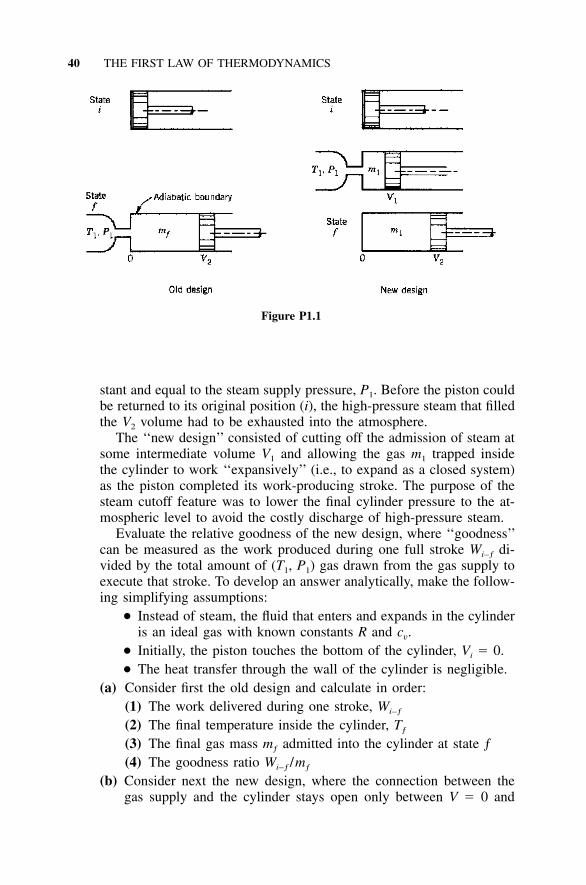
40 THE FIRST LAW OF THERMODYNAMICS
Figure P1.1
stant and equal to the steam supply pressure, P1. Before the piston couldbe returned to its original position (i), the high-pressure steam that filledthe V2 volume had to be exhausted into the atmosphere.
The ‘‘new design’’ consisted of cutting off the admission of steam atsome intermediate volume V1 and allowing the gas m1 trapped insidethe cylinder to work ‘‘expansively’’ (i.e., to expand as a closed system)as the piston completed its work-producing stroke. The purpose of thesteam cutoff feature was to lower the final cylinder pressure to the at-mospheric level to avoid the costly discharge of high-pressure steam.
Evaluate the relative goodness of the new design, where ‘‘goodness’’can be measured as the work produced during one full stroke Wi–ƒ di-vided by the total amount of (T1, P1) gas drawn from the gas supply toexecute that stroke. To develop an answer analytically, make the follow-ing simplifying assumptions:
● Instead of steam, the fluid that enters and expands in the cylinderis an ideal gas with known constants R and cv.
● Initially, the piston touches the bottom of the cylinder, Vi � 0.● The heat transfer through the wall of the cylinder is negligible.
(a) Consider first the old design and calculate in order:(1) The work delivered during one stroke, Wi–ƒ
(2) The final temperature inside the cylinder, Tƒ
(3) The final gas mass mƒ admitted into the cylinder at state ƒ(4) The goodness ratio Wi–ƒ /mƒ
(b) Consider next the new design, where the connection between thegas supply and the cylinder stays open only between V � 0 and

PROBLEMS 41
Figure P1.3
V � V1. The expansion from V � V1 to V � V2 can be modeled asreversible and adiabatic. Calculate in order:(1) The ideal gas mass m1 trapped in the cylinder at V � V1 and
later(2) The work delivered during one stroke, Wi–ƒ
(3) The goodness ratio Wi–ƒ /m1
(c) Show that the goodness ratio of the new design is greater than thegoodness ratio of the old design.
1.2 One kilogram of H2O (the ‘‘system’’) is being heated in a rigid con-tainer. In the initial state, the system is a mixture of liquid water andsteam of temperature T1 � 100�C and vapor quality x1 � 0.5. The totalheat transfer experienced by the system from state 1 to state 2 is Q1–2
� 2199.26 kJ.(a) Draw the path of the process on a P–v diagram.(b) Pinpoint the final state 2; that is, determine two independent prop-
erties of the system at state 2.(c) Determine T2 and P2.(d) Comment on the dependence of the system’s internal energy on
temperature at states near state 2. For example, can H2O be modeledas an ideal gas in the vicinity of state 2?
1.3 An amount of ideal gas m (with known constants R and cv) is confinedby means of two rigid and diathermal diaphragms and one floating pis-ton in three compartments, as shown in Fig. P1.3. Each compartmentcontains one-third of the amount of ideal gas; however, the pressurediffers from one compartment to the next (pressures P1A, P1B, and P1C
are known). The three compartments are initially in thermal equilibriumat temperature T1.

42 THE FIRST LAW OF THERMODYNAMICS
Consider next the adiabatic process 1 → 2 triggered when the twodiaphragms are punctured. In the end (at state 2), the ideal gas is char-acterized by a unique pressure P2 and a unique temperature T2. Deter-mine the final temperature T2 and show that your conclusion can beshaped as follows:
T R P P2 1A 1A� function , ,� �T c P P1 v 1B 1C
1.4 During its warm-up phase and before the pressure-release safety valveopens, a pressure cooker can be modeled as a constant-volume rigidcontainer that is being heated at a rate Q. Let m be the mass of theliquid–water vapor mixture at some point in time t when the quality ofthe mixture is x and the pressure is P. Assuming that Q, x, and P areknown, determine analytically the rate of pressure increase in the pres-sure cooker (dP /dt) as a function of Q, m, x, and various properties ofthe saturated states ƒ (liquid) and g (gas) that correspond to pressure P.
1.5 The air from a glass tube has been evacuated completely before the tipof the tube was fused and sealed. You are invited to break the tip of thetube, wait a second or two, and dip the open end of the tube into abeaker containing some water. Do you expect the water to rise into theglass tube, or do you expect air bubbles to come out of the tube intothe water? Explain the basis for your expectations [47].
1.6 A rigid container with volume V is originally filled with water of tem-perature T1. A hose is then connected to an inlet port and hotter waterof temperature T2 is pumped into the container at a mass flow rate
while another venting port allows the displaced water to flow out,m ,in
the pressure being constant.Assume that inside the container the incoming hot water mixes
quickly with the water inside, so that the temperature is to a good ap-proximation uniform. The water can be viewed as an incompressibleliquid with constant specific volume vw and with du � c dT, where thespecific heat c is given.(a) Treating the container as an open system, derive an expression for
the temperature T inside the container as a function of time. Neglecteffects due to gravity and kinetic energy.
(b) Suppose that the container has a volume of 1 m3 and vw � 10�3
m3/kg. If T1 � 10�C and T2 � 40�C, what hot water mass must bepumped into the container to raise the inside temperature from 10�Cto 20�C?
1.7 A rigid and well-insulated container holds 1 kg of dry saturated steamat P1 � 5 MPa. At some point in time, a tiny crack develops in the
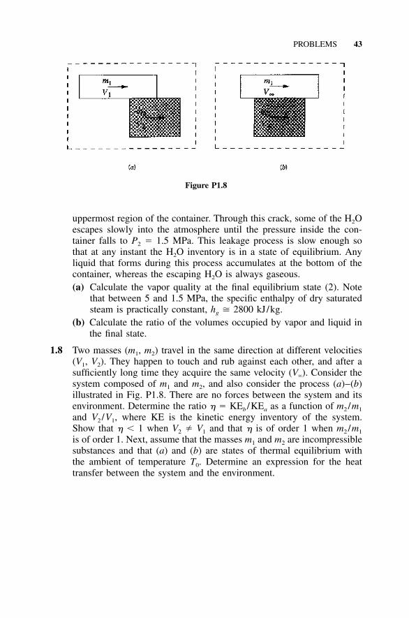
PROBLEMS 43
Figure P1.8
uppermost region of the container. Through this crack, some of the H2Oescapes slowly into the atmosphere until the pressure inside the con-tainer falls to P2 � 1.5 MPa. This leakage process is slow enough sothat at any instant the H2O inventory is in a state of equilibrium. Anyliquid that forms during this process accumulates at the bottom of thecontainer, whereas the escaping H2O is always gaseous.(a) Calculate the vapor quality at the final equilibrium state (2). Note
that between 5 and 1.5 MPa, the specific enthalpy of dry saturatedsteam is practically constant, hg 2800 kJ/kg.
(b) Calculate the ratio of the volumes occupied by vapor and liquid inthe final state.
1.8 Two masses (m1, m2) travel in the same direction at different velocities(V1, V2). They happen to touch and rub against each other, and after asufficiently long time they acquire the same velocity (V�). Consider thesystem composed of m1 and m2, and also consider the process (a)–(b)illustrated in Fig. P1.8. There are no forces between the system and itsenvironment. Determine the ratio � � KEb /KEa as a function of m2 /m1
and V2 /V1, where KE is the kinetic energy inventory of the system.Show that � � 1 when V2 � V1 and that � is of order 1 when m2 /m1
is of order 1. Next, assume that the masses m1 and m2 are incompressiblesubstances and that (a) and (b) are states of thermal equilibrium withthe ambient of temperature T0. Determine an expression for the heattransfer between the system and the environment.