the first albany building - penn state engineering · pdf filethe first albany building 677...
TRANSCRIPT

AE Structural Concepts & Existing
Conditions Report
Gerald Craig
Technical Report 1
Page 1 of 22
The First Albany Building 677 Broadway
Albany, NY
Gerald Craig
Architectural
Engineering
Structural option
Consultant:
Dr. Boothby
October 6, 2009

AE Structural Concepts & Existing
Conditions Report
Gerald Craig
Technical Report 1
Page 2 of 22
TABLE OF CONTENTS Executive Summary 3 Introduction 4 Applicable Building Codes & Building Design Loads
5
Structural System Discussion 6 Wind Loads 7 Seismic Loads 8 Conclusion 9 Appendices
Appendix A – Project Team Directory Appendix B – Figures Appendix C – Seismic Load Calculations Appendix D – Spot Check Calculations Appendix E – Photos
10
11 - 16 17
18 - 19 20 - 21
AE Structural Concepts & Existing
Conditions Report
Gerald Craig
Technical Report 1
Page 3 of 22
EXECUTIVE SUMMARY The First Albany Building is a 12 story, 180,000 square feet structure designed to house mixed-use office space and condominiums. Dimensions of the building are roughly 115’ x 135’ and the overall height is about 172’ to the mechanical penthouse roof. The first floor is at grade and the building has no basement. The exterior of the building is mostly brick veneer. The foundation system consists of a mixture of H piles, pile caps, and grade beams to support the structure. The first floor is supported by a 6” concrete slab on grade with the remaining 11 stories (and roof) comprised of a semi-regular grid of simply supported beams and girders. Floor slabs are 4.5” thick on a composite steel deck. Composite steel and concrete design was utilized in the floor members (partial composite action). Lateral forces are resisted by sets of concentrically braced steel frames around the core of the building. Bracing patterns include "K", inverted "K", and standard diagonal. The braced frames each act like a vertical, cantilevered truss. There are 2 wide frames in the east-west direction and 3 narrower frames in the north-south direction. Live loads used by the engineer were found to be 70 psf for the lower floors and 115 psf for the upper floors. Live loads required by ASCE 7-05 Chapter 4 were found to be roughly the same. Spot checks of existing structural elements’ performance and serviceability confirmed that the loads calculated were close to those used by the design engineer. ASCE 7-05 was used to determine all wind and seismic loads. For wind loads Method 2 (Analytical procedure) of ASCE 7-05 Chapter 6 was used. Design wind velocity was found to be 90 mph. Seismic design loads were established using the equivalent lateral force procedure outlined in ASCE 7-05 Chapter 12. The First Albany Building was found to be in a Seismic Design Category “B”.

AE Structural Concepts & Existing
Conditions Report
Gerald Craig
Technical Report 1
Page 4 of 22
INTRODUCTION
Building Description
The First Albany Building is a 12 story, 180,000 square feet structure designed to house mixed-use office space and condominiums. Dimensions of the building are roughly 115’ x 135’ and the overall height is about 172’ to the mechanical penthouse roof. The first floor is at grade and the building has no basement. The exterior of the building is mostly brick veneer.
The foundation system consists of a mixture of H piles, pile caps, and grade beams to support the structure. The first floor is supported by a 6” concrete slab on grade with the remaining 11 stories (and roof) comprised of a semi-regular grid of simply supported beams and girders. H-piles had to be driven to practical refusal to fully support the building. Six test piles were driven and their capacities tested to verify calculated load capacities of all the piles. Design capacity of each pile was 120 tons.
Gravity loads are resisted by a 4.5" reinforced concrete slab utilizing composite deck design. The floor slab is supported by a semi-regular grid of simply supported beams and girders. Composite beam and composite deck design (partial composite action) was incorporated in to the floor system design and bays are typically about 25'x25' with some variations. Sizes of floor members range between W12 and W18 shapes with varying numbers of shear stud connectors on each member. Column lines transfer loads directly to the ground through pile caps and to the piles themselves. The piles are laid out symmetrically under each cap because there are no eccentricities associated with column loads. Lateral forces are resisted by sets of concentrically braced steel frames around the core of the building. Bracing patterns include "K", inverted "K", and standard diagonal. The braced frames each act like a vertical, cantilevered truss. There are 2 wide frames in the east-west direction and 3 narrower frames in the north-south direction. Material specifications
Structural Steel –
Miscellaneous shapes, plates, bars – ASTM A36, Fy = 36 ksi Structural Shapes, W8 and larger – ASTM A572, Grade 50, Fy = 50 ksi Hollow Structural Shapes (HSS) – A500, Grade B, Fy = 46 ksi (square and rect.) – ASTM A53, Type E or S, Fy = 35 ksi (round shapes) Anchor Bolts – ASTM A307 – ASTM A449 (at braced bays) Cast-in-place Concrete –
Slab on Grade – 3500 psi (28 day compressive strength) Supported Floor Slabs – 4000 psi, lightweight (115 pcf) Grade Beams, Pile Caps, Walls – 4000 psi Foundation Piers – 6000 psi Reinforcing bars – ASTM A615, Grade 60, deformed Welded Reinforcing bars – ASTM A706, Grade 60 Welded Wire Fabric – ASTM A185 (Sheet type only)
Steel Deck –
Roof Deck – 1 ½” x 22 Gage Type B Rib Deck Floor Deck – 2” x 22 Gage Composite Floor Deck

AE Structural Concepts & Existing
Conditions Report
Gerald Craig
Technical Report 1
Page 5 of 22
APPLICABLE BUILDING CODES New York State Building Code 2002 New York State Energy Conservation Code “Manual of Steel Construction” AISC ASD 9th Ed. ”Building Code Requirements for Structural Concrete” ACI 318-02 Gravity Live Loads Loading Used by Engineer ASCE 7-05 Required Loading
Office Space (2-8) 50 psf +20 psf Partition Allowance
50 +15
psf (ASCE 7-05, Table 4.1) (Partition Allowance)
Office Space (9-12) +Computer Use
100 psf +15 psf Access Flooring
100 psf (ASCE 7-05 Table 4.1)
Office Space File Storage
125 psf 125 psf (ASCE 7-05 Table 4.1)
Stairways 100 psf 100 psf (ASCE 7-05 Table 4.1) Roof Snow Load 65 psf 65 psf (NYS Bldg Code) Balconies 100 psf 100 psf (ASCE 7-05 Table 4.1) Roof 20 psf 20 psf (ASCE 7-05 Table 4.1) Restaurants 100 psf 100 psf (ASCE 7-05 Table 4.1) Dead Loads Loading
MEP 15 psf Structural Steel 15 psf Concrete Slab 43 psf Deck 2 psf Finishes 5 psf Misc 10 psf
Total 90 psf Live Load Reductions Reduction Factor (RF) = 0.25+15/√(KLL*A T) For structural members supporting 1 floor; RF ≥ 0.5
For structural members supporting 2 or more floors; RF ≥ 0.4
AE Structural Concepts & Existing
Conditions Report
Gerald Craig
Technical Report 1
Page 6 of 22
STRUCTURAL SYSTEM DISCUSSION
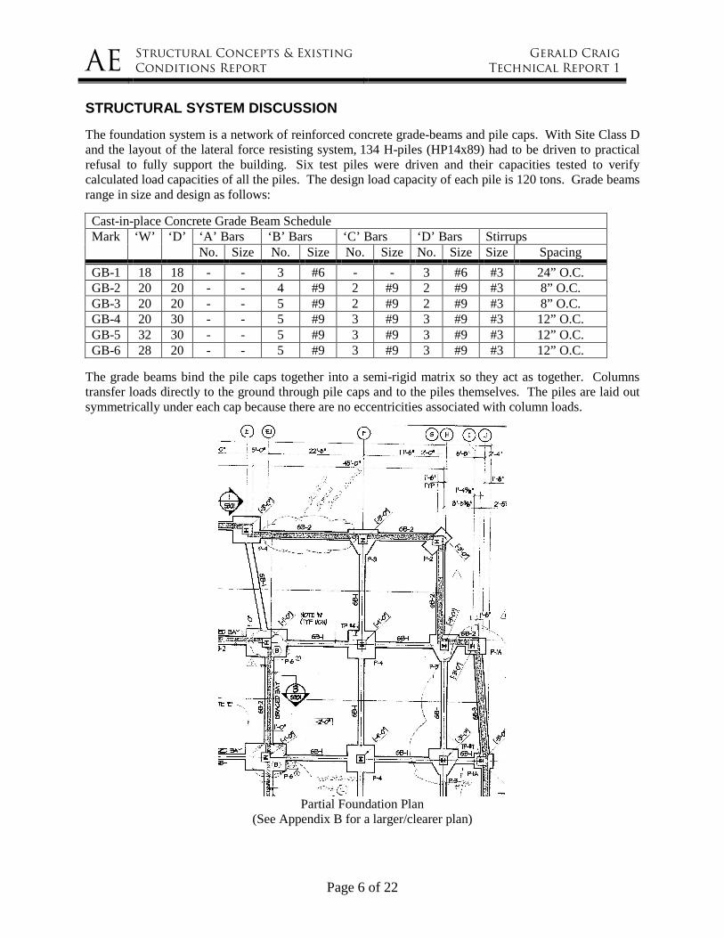
The foundation system is a network of reinforced concrete grade-beams and pile caps. With Site Class D and the layout of the lateral force resisting system, 134 H-piles (HP14x89) had to be driven to practical refusal to fully support the building. Six test piles were driven and their capacities tested to verify calculated load capacities of all the piles. The design load capacity of each pile is 120 tons. Grade beams range in size and design as follows:
Cast-in-place Concrete Grade Beam Schedule ‘A’ Bars ‘B’ Bars ‘C’ Bars ‘D’ Bars Stirrups Mark ‘W’ ‘D’ No. Size No. Size No. Size No. Size Size Spacing
GB-1 18 18 - - 3 #6 - - 3 #6 #3 24” O.C. GB-2 20 20 - - 4 #9 2 #9 2 #9 #3 8” O.C. GB-3 20 20 - - 5 #9 2 #9 2 #9 #3 8” O.C. GB-4 20 30 - - 5 #9 3 #9 3 #9 #3 12” O.C. GB-5 32 30 - - 5 #9 3 #9 3 #9 #3 12” O.C. GB-6 28 20 - - 5 #9 3 #9 3 #9 #3 12” O.C.
The grade beams bind the pile caps together into a semi-rigid matrix so they act as together. Columns transfer loads directly to the ground through pile caps and to the piles themselves. The piles are laid out symmetrically under each cap because there are no eccentricities associated with column loads.
Partial Foundation Plan
(See Appendix B for a larger/clearer plan)
AE Structural Concepts & Existing
Conditions Report
Gerald Craig
Technical Report 1
Page 7 of 22
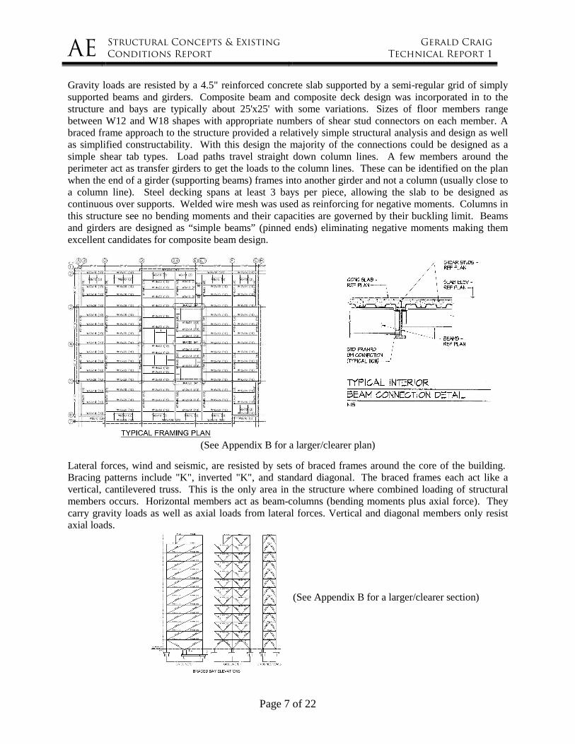
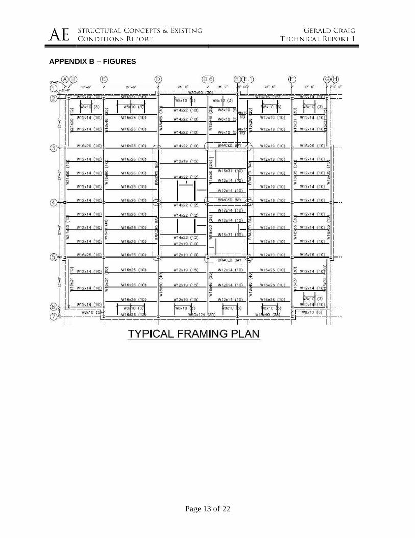
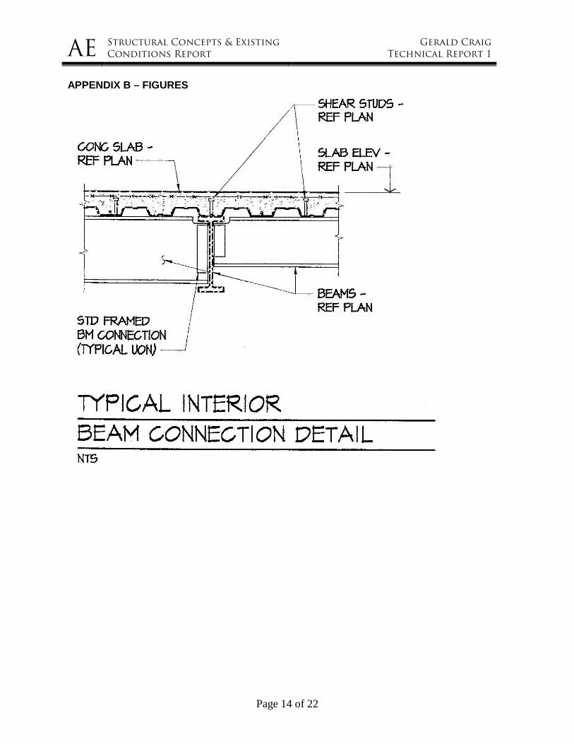
Gravity loads are resisted by a 4.5" reinforced concrete slab supported by a semi-regular grid of simply supported beams and girders. Composite beam and composite deck design was incorporated in to the structure and bays are typically about 25'x25' with some variations. Sizes of floor members range between W12 and W18 shapes with appropriate numbers of shear stud connectors on each member. A braced frame approach to the structure provided a relatively simple structural analysis and design as well as simplified constructability. With this design the majority of the connections could be designed as a simple shear tab types. Load paths travel straight down column lines. A few members around the perimeter act as transfer girders to get the loads to the column lines. These can be identified on the plan when the end of a girder (supporting beams) frames into another girder and not a column (usually close to a column line). Steel decking spans at least 3 bays per piece, allowing the slab to be designed as continuous over supports. Welded wire mesh was used as reinforcing for negative moments. Columns in this structure see no bending moments and their capacities are governed by their buckling limit. Beams and girders are designed as “simple beams” (pinned ends) eliminating negative moments making them excellent candidates for composite beam design.
(See Appendix B for a larger/clearer plan)
Lateral forces, wind and seismic, are resisted by sets of braced frames around the core of the building. Bracing patterns include "K", inverted "K", and standard diagonal. The braced frames each act like a vertical, cantilevered truss. This is the only area in the structure where combined loading of structural members occurs. Horizontal members act as beam-columns (bending moments plus axial force). They carry gravity loads as well as axial loads from lateral forces. Vertical and diagonal members only resist axial loads.
(See Appendix B for a larger/clearer section)
AE Structural Concepts & Existing
Conditions Report
Gerald Craig
Technical Report 1
Page 8 of 22
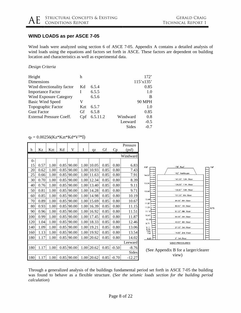
WIND LOADS as per ASCE 7-05 Wind loads were analyzed using section 6 of ASCE 7-05. Appendix A contains a detailed analysis of wind loads using the equations and factors set forth in ASCE. These factors are dependent on building location and characteristics as well as experimental data. Design Criteria Height h 172’ Dimensions 115’x135’ Wind directionality factor Kd 6.5.4 0.85 Importance Factor I 6.5.5 1.0 Wind Exposure Category 6.5.6 B Basic Wind Speed V 90 MPH Topographic Factor Kzt 6.5.7 1.0 Gust Factor Gf 6.5.8 0.85 External Pressure Coeff. Cpf 6.5.11.2 Windward 0.8 Leeward -0.5 Sides -0.7 qz = 0.00256(Kz*Kzt*Kd*V²*I)
(See Appendix B for a larger/clearer
view)
Through a generalized analysis of the buildings fundamental period set forth in ASCE 7-05 the building was found to behave as a flexible structure. (See the seismic loads section for the building period calculation)
h Kz Kzt Kd V I qz Gf Cp Pressure
(psf)
Windward 0-15 0.57 1.00 0.85 90.00 1.00 10.05 0.85 0.80 6.83 20 0.62 1.00 0.85 90.00 1.00 10.93 0.85 0.80 7.43 25 0.66 1.00 0.85 90.00 1.00 11.63 0.85 0.80 7.91 30 0.70 1.00 0.85 90.00 1.00 12.34 0.85 0.80 8.39 40 0.76 1.00 0.85 90.00 1.00 13.40 0.85 0.80 9.11 50 0.81 1.00 0.85 90.00 1.00 14.28 0.85 0.80 9.71 60 0.85 1.00 0.85 90.00 1.00 14.98 0.85 0.80 10.19 70 0.89 1.00 0.85 90.00 1.00 15.69 0.85 0.80 10.67 80 0.93 1.00 0.85 90.00 1.00 16.39 0.85 0.80 11.15 90 0.96 1.00 0.85 90.00 1.00 16.92 0.85 0.80 11.51
100 0.99 1.00 0.85 90.00 1.00 17.45 0.85 0.80 11.87 120 1.04 1.00 0.85 90.00 1.00 18.33 0.85 0.80 12.46 140 1.09 1.00 0.85 90.00 1.00 19.21 0.85 0.80 13.06 160 1.13 1.00 0.85 90.00 1.00 19.92 0.85 0.80 13.54 180 1.17 1.00 0.85 90.00 1.00 20.62 0.85 0.80 14.02
Leeward 180 1.17 1.00 0.85 90.00 1.00 20.62 0.85 -0.50 -8.76
Sides 180 1.17 1.00 0.85 90.00 1.00 20.62 0.85 -0.70 -12.27

AE Structural Concepts & Existing
Conditions Report
Gerald Craig
Technical Report 1
Page 9 of 22
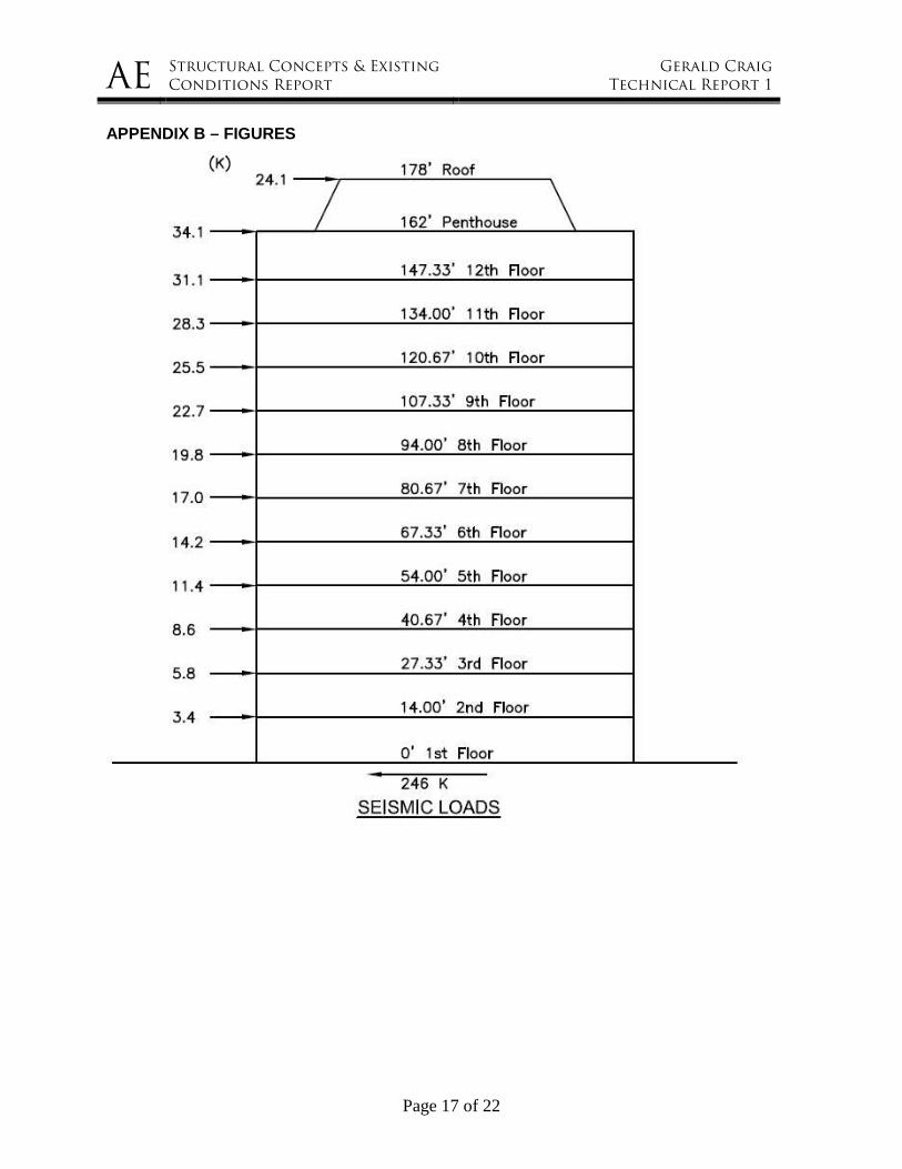
SEISMIC LOADS as per ASCE 7-05 Seismic loads were found using the applicable sections of ASCE 7-05; Equivalent Lateral Force procedure (12.8). All factors and accelerations were found using the tables and equations contained in ASCE. All dead loads used are based on ASCE 7-05 and are listed in the gravity loads section of this report. Site Class D Occupancy Category II Importance Factor 1.0 Seismic Design Category B Response Modification Factor (R) 5 Period (Ta) 1.46 Ss 0.229 * S1 0.069 * SDS 0.28 SD1 0.12 TL 6 Figure 22-15 Cs 0.016 Base Shear (V) 246 (K) *From USGS website - earthquake.usgs.gov/research/hazmaps/design
(See Appendix B for a larger/clearer
view)
Level wx hf hx wx(hx)^k Fx Vx Mx (k) (ft) (ft) (K) (K) (FT-K)
Pent 750 16.00 178.00 133500.0 24.1 0.0 4286.5 12 1170 14.67 162.00 189540.0 34.2 24.1 5538.8 11 1170 13.33 147.33 172380.0 31.1 58.3 4581.3 10 1170 13.33 134.00 156780.0 28.3 89.4 3789.6 9 1170 13.33 120.67 141180.0 25.5 117.6 3073.0 8 1170 13.33 107.33 125580.0 22.7 143.1 2431.4 7 1170 13.33 94.00 109980.0 19.8 165.8 1864.9 6 1170 13.33 80.67 94380.0 17.0 185.6 1373.3 5 1170 13.33 67.33 78780.0 14.2 202.6 956.9 4 1170 13.33 54.00 63180.0 11.4 216.8 615.4 3 1170 13.33 40.67 47580.0 8.6 228.2 349.0 2 1170 13.33 27.33 31980.0 5.8 236.8 157.7 1 1350 14.00 14.00 18900.0 3.4 242.6 47.7
Total 14970 1363740.0 246.0 246.0 29065.7
AE Structural Concepts & Existing
Conditions Report
Gerald Craig
Technical Report 1
Page 10 of 22
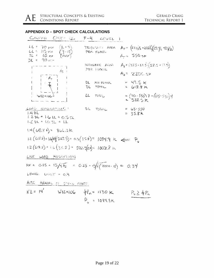
CONCLUSIONS In the first technical report the existing structural conditions were introduced through a detailed description of the foundation, gravity load resisting and lateral load resisting systems. Structural concepts were investigated including determining loads on the lateral force resisting system. Spot checks of gravity loads were done on typical beams, girders, and columns under design loads. W shapes as noted in the calculations were found adequate to resist moments, shears, and/or axial forces resulting from typical uniform dead and live loads. A more in depth analysis containing the analysis of the gravity and lateral loads in the structural frame as well as addressing serviceability requirements will be contained in a later report. The results of the gravity load spot checks have been presented in Appendix D. ASCE 7-05 was used to determine all wind and seismic loads. For wind loads Method 2 (Analytical procedure) of ASCE 7-05 section 6 was used. Seismic design loads were established using the equivalent lateral force procedure set forth in ASCE 7-05. Seismic load calculations have been presented in Appendix C.

AE Structural Concepts & Existing
Conditions Report
Gerald Craig
Technical Report 1
Page 11 of 22
APPENDIX A – PROJECT TEAM MEMBERS
Owner & Developer
Columbia Development Companies 302 Washington Ave. Ext., Albany, NY 12203 http://www.columbiadev.com/
Architect
HCP Architects 302 Washington Ave. Ext., Albany, NY 12203 http://www.hcpdesign.com/
Construction Manager & General Contractor
BBL Construction Services 302 Washington Ave. Ext., Albany, NY 12203 http://www.bblconstructionservices.com/
Structural Engineers
Stroud, Pence, & Associates LTD 204-A Grayson Road, Virginia Beach, VA 23462 http://www.stroudpence.com/
Site Engineers & Surveyor
Hershberg & Hershberg 18 Locust Street, Albany, NY 12203 http://www.hhershberg.com/
Geotechnical Engineers
Dente Engineering, P.C. 594 Broadway, Watervliet, NY 12189 http://www.dente-engineering.com/
Interior Designer / Architect Woodward, Connor, Gillies, & Seleman 20 Corporate Woods Blvd, Albany, NY 12211 http://www.wcgsarchitects.com/

AE Structural Concepts & Existing
Conditions Report
Gerald Craig
Technical Report 1
Page 12 of 22
APPENDIX B – FIGURES
PARTIAL FOUNDATION LAYOUT
AE Structural Concepts & Existing
Conditions Report
Gerald Craig
Technical Report 1
Page 13 of 22
APPENDIX B – FIGURES
AE Structural Concepts & Existing
Conditions Report
Gerald Craig
Technical Report 1
Page 14 of 22
APPENDIX B – FIGURES

AE Structural Concepts & Existing
Conditions Report
Gerald Craig
Technical Report 1
Page 15 of 22
APPENDIX B – FIGURES

AE Structural Concepts & Existing
Conditions Report
Gerald Craig
Technical Report 1
Page 16 of 22
APPENDIX B – FIGURES
AE Structural Concepts & Existing
Conditions Report
Gerald Craig
Technical Report 1
Page 17 of 22
APPENDIX B – FIGURES

AE Structural Concepts & Existing
Conditions Report
Gerald Craig
Technical Report 1
Page 18 of 22
APPENDIX C – SEISMIC LOAD CALCULATIONS
AE Structural Concepts & Existing
Conditions Report
Gerald Craig
Technical Report 1
Page 19 of 22
APPENDIX D – SPOT CHECK CALCULATIONS

AE Structural Concepts & Existing
Conditions Report
Gerald Craig
Technical Report 1
Page 20 of 22
APPENDIX C – SEISMIC LOAD CALCULATIONS
AE Structural Concepts & Existing
Conditions Report
Gerald Craig
Technical Report 1
Page 21 of 22
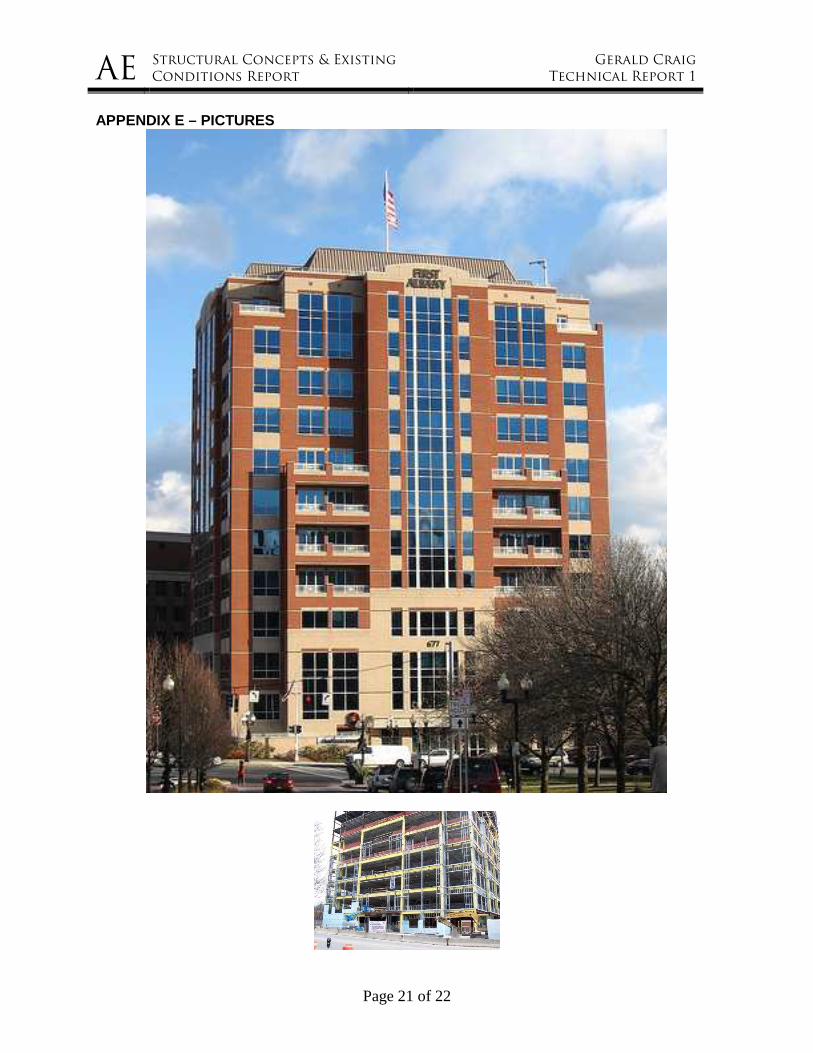
APPENDIX E – PICTURES

AE Structural Concepts & Existing
Conditions Report
Gerald Craig
Technical Report 1
Page 22 of 22
APPENDIX E – PICTURES