the electricity wiring regulations (third edition)
TRANSCRIPT

Th
e Electricity W
iring R
egulation
s (Th
ird E
dition
)
The ElectricityWiring Regulations(Third Edition)
Issued by:The Regulation and Supervision Bureaufor the water, wastewater and electricity sectorin the Emirate of Abu DhabiThe Electricity Wiring Regulations (Third Edition)
March 2014P
ublication
No. E
D/R
01/010


The Electricity Wiring Regulations
(Third Edition)
Issued by:the Regulation and Supervision Bureau
for the water, wastewater and electricity sector in the Emirate of Abu Dhabi
www.rsb.gov.ae
March 2014


The Electricity Wiring Regulations (Third Edition) 3
The Regulation and Supervision Bureau (the Bureau) is established in Abu Dhabi law to oversee the economic and technical activities of electricity, water and wastewater companies that are licensed to operate in the Emirate of Abu Dhabi.
In addition to its duties in respect of licensed companies, the Bureau has certain responsibilities towards the general public, including the assurance of safe and efficient electricity supplies to customers and these Regulations have been produced with this primary aim in mind.
The Regulations promote the installation and operation of safe electricity wiring systems in premises and are based on the general principles defined in British Standard BS 7671 (otherwise known as the IET Wiring Regulations, UK), which are also similar to the International Standard IEC 60364. Such principles are common practice in Abu Dhabi and were adopted in previous documents, including the first Wiring Regulations issued by the old Water and Electricity Department (WED) in 1972.
The Regulations also take account of the physical environment in Abu Dhabi and the skills and language diversity of the region.
These Regulations were first published in 2007 as the Electricity Wiring Regulations 2007 and were effective from 1 January 2008. The Bureau subsequently issued Revision 1 of the Regulations, which were effective from 1 January 2009. Following feedback from various parties, the Bureau issued its Third Edition of the Regulations, effective1 March 2014. The Regulations can be downloaded from the Bureau’s website, www.rsb.gov.ae.
Nicholas CarterDirector General
1 March 2014
Foreword

The Electricity Wiring Regulations (Third Edition)4
The Bureau gratefully acknowledges the contributions and comments provided by the following organisations:
Government organisations:
Al Ain Distribution Company (AADC)Abu Dhabi Distribution Company (ADDC)Abu Dhabi Municipality (ADM)Abu Dhabi Quality and Conformity Council (QCC)Abu Dhabi Urban Planning Council (UPC)Abu Dhabi Water and Electricity Authority (ADWEA)Al Mirfa Power Company (AMPC)Dubai Electricity and Water Authority (DEWA)Dubai Municipality (Central Laboratory)Emirates Standardization and Metrology Authority (ESMA)Federal Electricity and Water Authority (FEWA)Sharjah Electricity and Water Authority (SEWA)
Private organisations:
Anglian Power LTDBritish Standards Institute Cundall Johnston and Partners LLPElectrium LTD Hilson Moran Partnership LTDObermeyer Middle East GmbHParsons International LTDPower Economy Middle East LLCSchneider Electric FZESinyar Property Management LLCWSP Middle East LTD
In particular, the Bureau wishes to acknowledge permission granted by the Institute of Engineering Technology and the British Standards Institute for the use in this document of data and information taken from BS 7671:2008+A1:2011 (The IET Wiring Regulations, UK). BS 7671:2008 Incorporating Amendment No 1: 2011 can be purchased in hardcopy format only from the IET website http://electrical.theiet.org/ and the BSI online shop: http://shop.bsigroup.com.
Acknowledgements

The Electricity Wiring Regulations (Third Edition) 5
27
3
The Electricity Wiring Regulations (Third Edition)
General principles and safety requirements
3.1 Technical standards, materials and workmanship
3.1.1 These Regulations provide guidelines and technical standards which are consistent with the principles contained in BS 7671:2008 (also known as the IET Wiring Regulations 17th Edition). Where any provision in these Regulations contradicts any provision in BS 7671, the requirements, standards or specifications under these Regulations shall apply.
[Note: these Regulations are in some aspects more prescriptive than BS 7671, and take account of the physical environment of Abu Dhabi Emirate, as well as the typical skills and language diversity in the region.]
3.1.2 Where a provision or technical requirement is not covered by these Regulations, BS 7671 may be used as a guideline or specification, with prior approval from the Distribution Company and the Bureau.
3.1.3 All materials used in Electrical Installations shall be of good quality and installed in a neat and orderly manner.
3.1.4 All materials and equipment shall comply with relevant international standards which shall be mainly BS (British Standards) or IEC (International Electrotechnical Commission) standards, as referenced in these Regulations. Other international standards may be used, in particular where none are specified in these Regulations, with the prior approval of the Distribution Company and the Bureau. A list of BS and IEC standards applying to the main types of equipment is given in Appendix A3.
3.1.5 The Distribution Company may issue specifications and requirements in addition to these Regulations, which will be endorsed or approved by the Bureau, and provided to interested parties on request. The Distribution Company shall ensure that any such specifications or requirements are consistent with these Regulations, unless otherwise approved by the Bureau.
These Regulations use the following numbering system:
Chapters: are referenced by integers (e.g. 1, 2, 3, etc)
Regulations: are referenced by one full stop between numbers (e.g. 1.1, 1.2, etc)
Clauses: are referenced by two full stops between numbers (e.g. 3.1.2, etc)
Notes: are indicated below the clause in square brackets and italic text. For example, [Note: this clause does not apply to Electrical Installations that have been …]
Amendments: amended text is highlighted by a red margin (as amended in the Third Edition, March 2014)
Document numbering
Chapter
Note
Regulation
Clause
Amended text(Third Edition)

The Electricity Wiring Regulations (Third Edition)6
Publication Number
Date Prepared by:
Checked by:
Issued to:
ED/R01/010Issue 1 Dec 2007 T Khan L Hill Publication
ED/R01/010Revision 1 Jan 2009 T Khan L Hill Publication
ED/R01/010Third Edition Mar 2014 M Yousif
C K Lee M Preece Publication
List of publications

The Electricity Wiring Regulations (Third Edition) 7
Table of contents
Foreword 3Acknowledgements 4Document numbering 5List of publications 6
1 Introduction 11
1.1 Citation and commencement 111.2 Purpose and document structure 111.3 Scope and enforcement 12
2 Definitions 15
2.1 Interpretation 15
3 General principles and safety requirements 27
3.1 Technical standards, materials and workmanship 273.2 Approval of Electrical Installations 283.3 Extensions, alterations and repairs 293.4 Licensed Contractors 303.5 Requirements for safety 303.6 Labelling and identification 323.7 Environmental conditions 33
4 Electricity parameters and Electricity Intake 35
4.1 Electricity parameters 354.2 Electricity Intake 364.3 The Connection Point 384.4 Multiple occupancy Premises 384.5 Metering requirements 38
The Electricity Wiring Regulations (Third Edition)8
5 Protection 39
5.1 General principles 395.2 Overload and short-circuit protection 395.3 Electric shock protection 405.4 Earth Leakage Protected Systems 425.5 Earthed Equipotential Bonded Systems 455.6 Isolation and switching 475.7 Insulation 48
6 Earthing 51
6.1 General principles 516.2 Systems of Earthing 516.3 Main Earth Terminal 526.4 Earth Electrodes 536.5 Earth Conductors 556.6 Exposed-Conductive-Parts 566.7 Earth Fault Loop Impedance 576.8 Lightning protection 586.9 Functional Earthing and high leakage currents 59
7 Selection of components and installation requirements 61
7.1 Plugs, socket-outlets, and flex outlets 617.2 Switches and isolators 637.3 Lighting 647.4 Conduit, trunking and Cable Trays 677.5 Cables 697.6 Final Circuits 737.7 Busways, bus ducts and busbar risers 747.8 Distribution Boards 757.9 LV switchboards 79

The Electricity Wiring Regulations (Third Edition) 9
8 Inspection,testingandcertification 81
8.1 Inspection and testing by the Licensed Contractor 81
8.2 Inspection and testing by the Distribution Company 828.3 Electrical Installation Certificates 84
9 Special locations and systems 85
9.1 Separated Extra-Low Voltage 859.2 Protective Extra-Low Voltage 869.3 Bathrooms and similar locations 869.4 Swimming pools 889.5 Water fountains 899.6 Temporary Electrical Installations 909.7 Street lighting 929.8 External lighting 939.9 Marinas and similar locations 949.10 Solar photovoltaic systems 97
10 Power factor correction 103
10.1 General requirements 10310.2 Specifications for capacitors 104
11 Electric motors and starters 107 11.1 General requirements 10711.2 Protection and isolation 108
12 Standby generators 109
12.1 General requirements 109
Appendices 111
Guidance notes 209

The Electricity Wiring Regulations (Third Edition)10

The Electricity Wiring Regulations (Third Edition) 11
1Introduction
1.1 Citation and commencement
1.1.1 These Regulations shall be cited as the Electricity Wiring Regulations (Third Edition).
1.1.2 These Regulations are effective from 1 January 2008. Amendments incorporated in Revision 1 of the Regulations are effective from 1 January 2009. Amendments incorporated in this Third Edition of the Regulations are effective from 1 March 2014.
[Note: effective from 1 August 2013 the Bureau’s publications will be called ‘Editions’ instead of ‘Revisions’.]
1.1.3 These Regulations are issued by the Regulation and Supervision Bureau through the powers vested in it under Article 62 of Law No (2) of 1998 (as amended).
1.1.4 These Regulations supersede the following regulations:
(a) ADWEA’s Wiring Rules and Regulations (3rd Edition 2003);
(b) WED’s Regulations for Electrical Installation Works (1980); and
(c) Earth Leakage Protection Regulations (2001).
1.2 Purpose and document structure
1.2.1 The purpose of these Regulations is to establish standards and principles that promote the design, construction, installation, maintenance and operation of safe and efficient Low Voltage (LV) Electrical Installations in all Premises within the Emirate of Abu Dhabi.

The Electricity Wiring Regulations (Third Edition)12
11.2.2 The main part of this document is structured into chapters,
regulations and clauses, see illustration on page 5. Regulations and clauses are mandatory. Notes which are included below clauses, in italic text, are for guidance, clarification or provide supporting technical information.
1.2.3 The second part of this document consists of Appendices, which contain mandatory information, and Guidance notes which contain supporting information.
1.3 Scope and enforcement
1.3.1 These Regulations apply to all Distribution Companies, Customers, Owners, Licensed Contractors, or any other persons involved in the design, construction, installation, maintenance or operation of LV Electrical Installations in all Premises within the Emirate of Abu Dhabi. Such locations include, but are not limited to apartments, villas, offices, shops, warehouses, hotels, commercial complexes, leisure complexes, public buildings, parks, farms, temporary Electrical Installations, entertainment arenas, construction sites, tents, outbuildings, caravans, street lighting, and traffic signs.
[Note: certain Premises such as industrial, manufacturing, railway, oil and gas etc, due to the nature of their operation, may have specific requirements or standards that are not covered in these Regulations. In such cases, evidence of compliance with such requirements or standards must be provided to the relevant Distribution Company.]
1.3.2 The scope of these Regulations does not include the design and technical requirements of the High Voltage (HV) and LV electricity distribution networks belonging to Distribution Companies.
[Note: requirements governing Distribution Companies’ networks are covered under the Electricity Supply Regulations, as well as relevant Licences, codes and standards.]

The Electricity Wiring Regulations (Third Edition) 13
1
1n
trod
uct
ion
1.3.3 These Regulations shall apply to all new Electrical Installations constructed following the commencement date (clause 1.1.2). Requirements for extensions, alterations and repairs to existing Electrical Installations are covered under Regulation 3.3.
[Note: where the design of an Electrical Installation has been completed before the date of commencement of these Regulations advice must be sought from the Distribution Company before construction is commenced.]
1.3.4 For Electrical Installations constructed before the date of commencement (1 January 2008), the table in Appendix A4(a) lists those clauses that either do not apply or that apply after 1 January 2015 or the date of the next inspection or re-certification (whichever is the earlier).
1.3.5 These Regulations shall be enforced by the relevant Distribution Company in the Emirate of Abu Dhabi, in accordance with procedures which shall be published by the Distribution Company and approved by the Bureau. See Regulation 3.2.
1.3.6 Compliance with these Regulations requires compliance with other relevant technical standards, see Regulation 3.1. References to British Standards or other standards means the current edition of the standard cited or its replacement. For existing Electrical Installations clause 1.3.4 applies.
1.3.7 Failure to comply with these Regulations, or any part thereof, shall be deemed as contrary to the Law and subject to punishment by the imposition of a fine. Any such failures will be addressed in accordance with the Law under Article 65(5) (notices served by the Bureau) and Article 66 (failure to comply and imposition of fines). Action may be taken against any Distribution Company, Customer, Owner, Licensed Contractor or other person to which these Regulations apply.
[Note: see Appendix A4(b) for a list of relevant Articles of Law No (2) of 1998.]

The Electricity Wiring Regulations (Third Edition)14
11.3.8 Relaxation of any of the requirements of the Regulations
shall be approved by the Bureau upon written request by any Distribution Company, Customer, Owner, Licensed Contractor or other person. Such requests may be referred to a dispensation panel established for such purpose by the Bureau.
[Note: relaxation requests from a Customer, Owner, Licensed Contractor or other person must be directed to the relevant Distribution Company in the first instance, in accordance with the procedures published by the Company.]
1.3.9 In the event of a dispute between any parties mentioned in clause 1.3.1, the matter may be referred to the Bureau to advise a solution or recommended action. This does not preclude any party referring a matter to the relevant Court of Abu Dhabi.
1.3.10 These Regulations and the rights and duties of any parties thereunder shall be governed by, construed and applied in accordance with, the Laws of Abu Dhabi Emirate and the Federal Laws of the UAE as applied by the Courts of Abu Dhabi.

15
2
The Electricity Wiring Regulations (Third Edition)
2.1 Interpretation
Words which are defined under this section are used in the Regulations beginning with capital letters. For example, “all Earth Conductors within a Premises shall be ...”.
Terms in common use are not defined here and normal dictionary definitions apply (e.g. circuit-breaker, plug, conduit). Words and expressions other than those described in this section, which are defined in the Law, shall have the meanings ascribed to them in the Law.
Words using the singular or plural number also include the plural or singular number, respectively.
2.1.1 Accessory: a device, other than current-using equipment, associated with an Electrical Installation.
2.1.2 Appliance: an item of current-using equipment.
2.1.3 Arm’s Reach: a zone of accessibility to touch, extending from any point on a surface where a person may stand or move about, to the limits which such person may reach without assistance (i.e. without any tool or ladder, etc). Such a distance may be taken as 2.5 m height from the standing surface, and 1.25 m horizontally from the standing position.
2.1.4 Bureau: the Regulation and Supervision Bureau for the Water, Wastewater and Electricity Sector in the Emirate of Abu Dhabi, as established under the Law.
2.1.5 Cable Tray: a cable support consisting of a continuous base with raised edges and no covering. A Cable Tray is considered to be perforated where more than 30% of the material is removed from the base.
2.1.6 Cable Trunking: a manufactured enclosure for the protection of cables, normally of rectangular cross-section, of which one side is removable or hinged.
Definitions
16 The Electricity Wiring Regulations (Third Edition)
2
2.1.7 Category 1 Circuit: a Circuit (other than a fire alarm or emergency lighting Circuit) operating at LV.
2.1.8 Category 2 Circuit: a Circuit (other than a fire alarm or emergency lighting Circuit) which supplies telecommunications equipment (such as telephones, intruder alarms, data transmission, call bells, etc).
2.1.9 Category 3 Circuit: a fire alarm or emergency lighting Circuit.
2.1.10 Circuit: a set of phase and neutral conductors installed as a group to supply power to a location and which originate from one Protective Device. The following are related definitions:
(a) Ring Circuit: a Circuit which is wired from a single Protective Device, being run through an area to be supplied (via appropriate socket-outlets, switched flex outlets, etc) and returning back to the same Protective Device, thus forming an electrically continuous loop;
(b) Radial Circuit: a Circuit which is wired in a ‘radial’ or ‘branch’ configuration, emanating from a Protective Device, to the area to be supplied;
(c) Final Circuit: a Circuit which directly supplies Appliances (normally via socket-outlets, switched flex outlets, isolators, ceiling roses, etc.); and
(d) Distribution Circuit: a Circuit connecting between Distribution Boards (may also be referred to as a ‘sub-Circuit’).
2.1.11 Class I Equipment: equipment which includes a means for connection of Exposed-Conductive-Parts of the equipment to the Earth Conductor, thus providing protection against electric shock in case of failure of the basic insulation of the equipment or other fault condition.
17
Defi
nitions
The Electricity Wiring Regulations (Third Edition)
2
2.1.12 Class II Equipment: equipment which does not include a means for connection to an Earth Conductor, and which provides supplementary insulation in addition to the basic insulation of the equipment such that a breakdown of the basic insulation will not present a dangerous Voltage on Exposed-Conductive-Parts (also known as Double Insulated Equipment). Class II Equipment is required to comply with BS 2754. See Appendix A18(b).
2.1.13 Class III Equipment: equipment in which protection against electric shock relies on supply at SELV and in which Voltages higher than SELV are not generated in the equipment, see BS 2754.
2.1.14 Competency Licence: a specific licence issued by a Distribution Company to a Licenced Contractor assessed as competent for work on LV Electrical Installations.
2.1.15 Connected Load: the aggregate load of Appliances and other electrical equipment at a Premises, summated using the method described under clause 3.2.7. See Guidance note G2.
2.1.16 Customer: any person, corporate body, or company who has an agreement with a Distribution Company for the supply of electricity.
2.1.17 Connection Point (CP): the point which defines the boundary between the Owner’s Electrical Installation installed at a Premises and the main cable or equipment owned by the Distribution Company.
2.1.18 Danger: risk of injury to people or animals from fire, electric shock, burns, explosion or from mechanical movement of electrically controlled equipment, or the risk of damage to property.
2.1.19 Direct Contact: the contact with electricity by a person (accidental or otherwise) through the phase or neutral conductors of an Electrical Installation or Appliance, leading to an electric shock, see Guidance note G4(a).

18 The Electricity Wiring Regulations (Third Edition)
2
2.1.20 Distribution Company: a company or body holding a distribution licence, granted by the Bureau, pursuant to the Law.
2.1.21 Distribution Board: an assembly designed for housing isolation switches and Protective Devices and for connecting multiple Circuits, including their associated neutral and Earth Conductors. The following are related definitions:
(a) Main Distribution Board (MDB): the Distribution Board which accepts the main incoming LV supply from the Distribution Company or Owner’s transformer;
(b) Sub Main Distribution Board (SMDB): any Distribution Board which is neither a Main Distribution Board nor a Final Distribution Board; and
(c) Final Distribution Board (FDB): a Distribution Board which supplies Final Circuits only.
2.1.22 Diversified Load: the load at a Distribution Board, at the Electricity Intake or at any other point in an Electrical Installation, calculated using diversity factors as illustrated in Guidance note G2.
2.1.23 Double Insulated Equipment: see Class II Equipment.
2.1.24 Earth: the conductive mass of Earth, whose electrical potential (Voltage) at any point is conventionally taken as zero. The following are related definitions:
(a) Locally Earthed System (TT): a system of supply where the Owner provides a Main Earth Terminal for the Electrical Installation, which is connected to a sufficient number of local Earth Electrodes to provide a maximum Earth Resistance measured at the Owner’s Main Earth Terminal of not more than 10 Ohms.

19
Defi
nitions
The Electricity Wiring Regulations (Third Edition)
2
(b) Distribution Company Earthed System (TN-S): a system of supply where the Distribution Company provides a connection to the Owner’s Main Earth Terminal, using the distribution network Earthing system.
2.1.25 Earthing or Earthed: a general term used to describe the connection of conductive parts of an Electrical Installation or an Appliance to Earth.
2.1.26 Earth Conductor: a conductor used to connect Exposed-Conductive-Parts of an Electrical Installation and associated Appliances to Earth, and providing a means for the safe passage of earth fault current. This includes the following defined terms:
(a) Main Earth Conductor (MEC): conductors connected between Earth Electrodes and Main Earth Terminals; and
(b) Circuit Earth Conductor (CEC): conductors connecting all Circuits emanating from Main Distribution Boards, Sub Main Distribution Boards, Final Distribution Boards including Circuits connecting to equipment and Appliances. Outside these Regulations these may also be known as the Circuit Protective Conductor (CPC) or Earth Continuity Conductor (ECC).
2.1.27 Earth Electrode: a conductor or group of conductors in intimate contact with Earth, providing an electrical connection to Earth, and normally having a known and measurable value of Earth Resistance.
2.1.28 Earthed Equipotential Bonding (EEB): the connection of Extraneous-Conductive-Parts within a Premises using designated conductors such that potential Touch Voltages are kept to a safe value during the passage of earth fault current (also known outside these Regulations as ‘PME Bonding’). This definition includes the following:

20 The Electricity Wiring Regulations (Third Edition)
2
(a) Main Equipotential Bonding: the connection of major Extraneous-Conductive-Parts, such as pipe services and metallic structures, at their point of entry into a Premises to the Main Earth Terminal in an Electrical Installation, using designated conductors; and
(b) Supplementary Equipotential Bonding: the connection of Extraneous-Conductive-Parts with each other or with Exposed-Conductive-Parts within an area where such parts are simultaneously accessible to persons, such that the potential Touch Voltage during an earth fault is kept to safe limits.
[Note: for disconnection times greater than 0.4 seconds, a safe Touch Voltage limit may be taken as 50 V for dry conditions and 25 V for wet conditions.]
2.1.29 Earthed Equipotential Bonded System (EEBS): a system where protection against electric shock due to Indirect Contact is achieved by the provision of Earthed Equipotential Bonding conductors, in association with Protective Devices for the automatic disconnection of supply.
2.1.30 Earth Leakage Protection (ELP): the provision of protection against electric shock due to Indirect Contact by the use of RCDs or other sensitive earth leakage Protective Devices which automatically disconnect the supply sufficiently quickly so as to prevent Danger to persons.
2.1.31 Earth Leakage Protected System (ELPS): a system of supply where Earth Leakage Protection is provided on Final Circuits and an additional ELP is provided at the Electricity Intake.
2.1.32 Earth Resistance: the resistance (in Ohms) from any point on an Electrical Installation to Earth, being measured using an approved testing device and approved procedure.

21
Defi
nitions
The Electricity Wiring Regulations (Third Edition)
2
2.1.33 Earth Fault Loop Impedance (Zs): the total impedance presented to an earth fault current, comprising the impedance of the following parts of a system, illustrated in Appendix A5(g):
(a) the Circuit Earth Conductor;
(b) the Main Earth Terminal;
(c) the main Earth Conductors connecting to Earth Electrodes or the Distribution Company Earth;
(d) the path of earth fault current through the general mass of Earth, or through the conductors or Earth sheath or armouring of the Distribution Company cable;
(e) the neutral Earth connection(s) of the Distribution Company;
(f) the distribution transformer winding; and
(g) the phase conductor of the Circuit back to the point of fault.
2.1.34 Electricity Intake: a term used to describe the location or room housing the Main Distribution Board and/or the main cable and equipment owned by a Distribution Company to which the Electrical Installation of the Premises is connected via a defined Connection Point.
2.1.35 Electrical Installation: an Electrical Installation comprises any fixed or temporary cable, switchgear or other electrical equipment or apparatus within a Premises or other place where there is an electricity supply (including outdoor locations). Fixed or portable electrical Appliances are not considered part of the Electrical Installation, although these Regulations do include requirements for the connection of Appliances (e.g. plugs and socket-outlets).

22 The Electricity Wiring Regulations (Third Edition)
2
2.1.36 Electrical Installation Certificate: a certificate in the format indicated in these Regulations which is issued by a Licensed Contractor after completion of work on an Electrical Installation and provided to the Customer or Owner of the Premises.
2.1.37 Electricity Distribution Code: a code prepared and maintained by the Distribution Companies detailing technical parameters and other requirements relating to the connection and the use of the distribution networks owned and operated by the Distribution Companies.
2.1.38 Exposed-Conductive-Part: a conductive part of an Electrical Installation or Appliance which can be touched by persons and which is not normally live but may become live due to a fault condition. Exposed-Conductive-Parts are required to be connected to Earth, see Regulation 6.6.
2.1.39 Extraneous-Conductive-Part: a conductive part, structure or any metalwork within a Premises which is not part of, and is unrelated to, the Electrical Installation and which is not designed to carry current, but which may become live due to a fault condition. Extraneous-Conductive-Parts are required to be connected to Earth for Electrical Installations or parts of Electrical Installations classified as Earthed Equipotential Bonded Systems, see Regulation 5.5.
2.1.40 Extra-Low Voltage (ELV): see Voltage.
2.1.41 Final Circuit: see Circuit.
2.1.42 Functional Earth: an Earth or Earthing system which is provided for special functions (such as reduction of radio frequency interference, noise filtering for computers, etc) and which is separate from other Earth Conductors in an Electrical Installation but is connected to the Main Earth Terminal.
2.1.43 High Voltage: see Voltage.
23
Defi
nitions
The Electricity Wiring Regulations (Third Edition)
2
2.1.44 Indirect Contact: contact of a person with electricity through Exposed-Conductive-Parts of an Electrical Installation or Appliance, or through Extraneous-Conductive-Parts in a Premises which have become live during fault conditions, see Guidance note G4(b).
2.1.45 Law: means Law No (2) of 1998 Concerning the Regulation of the Water, Wastewater and Electricity Sector in the Emirate of Abu Dhabi (as amended).
2.1.46 Licensed Contractor: a person, entity or company which has been assessed by the Distribution Company as competent to work on Electrical Installations and issued a Competency Licence by that Distribution Company.
2.1.47 Low Voltage: see Voltage.
2.1.48 Luminaire: equipment which is designed to house one or more electric lamps and which may include diffusers, fixtures, transformers and auxiliary Circuits but is taken to exclude the lamps themselves. Outside of these Regulations a Luminaire may commonly be referred to as a ‘light fitting’.
2.1.49 Main Distribution Board: see Distribution Board.
2.1.50 Main Earth Terminal (MET): the main Connection Point at which the nominal value of Earth Resistance for an Electrical Installation is taken, and to which Earth Conductors from Earth Electrodes or the Distribution Company Earth are connected. This will normally be at or close to the Connection Point.
2.1.51 Marina: a facility for the mooring of Leisure Crafts which has fixed wharves, jetties, piers or a pontoon arrangement capable of berthing one or more Leisure Craft. The following are related definitions:
(a) Leisure Craft: a boat, vessel, yacht, motor launch, houseboat or other floating craft used exclusively for sport or leisure; and

24 The Electricity Wiring Regulations (Third Edition)
2
(b) Pedestal: an electrical service enclosure providing electricity connection to Leisure Crafts in Marinas.
2.1.52 Owner: the legal owner of the Premises in which an Electrical Installation is installed.
2.1.53 Premises: any occupied or unoccupied land, structure, building, enclosure or other place. Such locations include, but are not limited to, apartments, villas, offices, shops, warehouses, hotels, commercial complexes, leisure complexes, public buildings, parks, farms, temporary Electrical Installations, entertainment arenas, construction sites, tents, outbuildings, caravans, street lighting and traffic signs.
2.1.54 Prospective Fault Current: the value of current that would flow due to a short-circuit fault of negligible impedance between live phase conductors, or between phase conductors and Earth. The maximum Prospective Fault Current for an Electrical Installation is normally taken at the Connection Point.
2.1.55 Protective Device: a device installed at the start of a Circuit which will automatically disconnect the input of electricity in the event of a fault or overload occurring on that Circuit. Such devices include, but are not limited to, fuses, fuse links, miniature circuit-breakers (MCB), moulded case circuit-breakers (MCCB) and Residual Current Devices (RCD).
2.1.56 PV: photovoltaic. The following are related definitions:
(a) a.c. side: part of a PV installation from the a.c. terminals of the PV Inverter to the point of connection of the PV supply cable to the Electrical Installation;
(b) Array: mechanically and electrically integrated assembly of PV Modules, and other necessary components, to form a d.c. power supply unit;

25
Defi
nitions
The Electricity Wiring Regulations (Third Edition)
2
(c) Array Junction Box: enclosure where PV Strings of any PV Array are electrically connected and where devices can be located;
(d) d.c. side: part of a PV installation from a PV cell to the d.c. terminals of the PV Inverter;
(e) Inverter: device which converts d.c. voltage and d.c. current into a.c. voltage and a.c. current;
(f) Module: smallest completely environmental protected assembly of interconnected PV cells;
(g) Open Circuit Voltage, Voc: voltage under standard test conditions across unloaded (open) PV Module, PV String, PV generator, or on the d.c. side of the PV Inverter;
(h) Short Circuit Current, Isc: short circuit current of a PV Module, PV String, PV Array or PV generator under standard test conditions; and
(i) String: Circuit in which PV Modules are connected in series, in order for a PV Array to generate the required output voltage.
2.1.57 Radial Circuit: see Circuit.
2.1.58 Residual Current Device (RCD): a Protective Device which is installed to automatically isolate the supply to a Circuit or Distribution Board when the vector sum of currents in the phase and neutral conductors reaches a preset value (referred to as the residual operating current or residual current rating).
2.1.59 Ring Circuit: see Circuit.
2.1.60 Sub Main Distribution Board: see Distribution Board.

26 The Electricity Wiring Regulations (Third Edition)
2
2.1.61 Touch Voltage: the Voltage that would appear during an earth fault condition between Exposed-Conductive-Parts and Extraneous-Conductive-Parts which are simultaneously accessible to persons.
[Note: this term is used only in connection with protection against Indirect Contact and is not used to refer to Direct Contact with electricity. The seriousness of impact of Touch Voltage on a person will depend on the body resistance and the immediate surroundings, in particular the presence of water. See Guidance note G4(h) and G5(b).]
2.1.62 Voltage:
(a) High Voltage (HV): an a.c. voltage greater than Low Voltage and less than 36 kV between phases or 21 kV between any phase and Earth (internationally referred to as Medium Voltage);
(b) Low Voltage (LV): an a.c. voltage below 1000 V between phases, or below 600 V between any phase and Earth or; a d.c. voltage below 1500 V between conductors, or below 900 V between any conductor and Earth;
(c) Extra-Low Voltage (ELV): a voltage not exceeding 50 V a.c. or 120 V d.c. whether between live conductors or between live conductors and Earth;
(d) Separated Extra-Low Voltage (SELV): an Extra-Low Voltage system which is electrically separated from Earth in such a way that a single fault cannot give rise to the risk of electric shock;
(e) Protective Extra-Low Voltage (PELV): a system which has the same features as SELV except that connection of Exposed-Conductive-Parts to Earth is allowed; and
(f) Reduced Low Voltage (RLV): a voltage which does not exceed 55 V a.c. between phase and Earth or 110 V a.c. between phases.

27
3
The Electricity Wiring Regulations (Third Edition)
General principles and safety requirements
3.1 Technical standards, materials and workmanship
3.1.1 These Regulations provide guidelines and technical standards which are consistent with the principles contained in BS 7671:2008 (also known as the IET Wiring Regulations 17th Edition). Where any provision in these Regulations contradicts any provision in BS 7671, the requirements, standards or specifications under these Regulations shall apply.
[Note: these Regulations are in some aspects more prescriptive than BS 7671, and take account of the physical environment of Abu Dhabi Emirate, as well as the typical skills and language diversity in the region.]
3.1.2 Where a provision or technical requirement is not covered by these Regulations, BS 7671 may be used as a guideline or specification, with prior approval from the Distribution Company and the Bureau.
3.1.3 All materials used in Electrical Installations shall be of good quality and installed in a neat and orderly manner.
3.1.4 All materials and equipment shall comply with relevant international standards which shall be mainly BS (British Standards) or IEC (International Electrotechnical Commission) standards, as referenced in these Regulations. Other international standards may be used, in particular where none are specified in these Regulations, with the prior approval of the Distribution Company and the Bureau. A list of BS and IEC standards applying to the main types of equipment is given in Appendix A3.
3.1.5 The Distribution Company may issue specifications and requirements in addition to these Regulations, which will be endorsed or approved by the Bureau, and provided to interested parties on request. The Distribution Company shall ensure that any such specifications or requirements are consistent with these Regulations, unless otherwise approved by the Bureau.

28 The Electricity Wiring Regulations (Third Edition)
3
3.1.6 Reference must be made, where relevant, to UAE or Gulf standards which may be issued from time to time by the Emirates Standardization and Metrology Authority (ESMA).
3.2 Approval of Electrical Installations
3.2.1 Any Owner requiring a new connection or alteration to an existing connection must make an application to the Distribution Company using the appropriate forms and procedures published by the Company.
3.2.2 The design of an Electrical Installation must be approved by the Distribution Company before commencement of construction. Details of the design must be submitted, together with appropriate calculations and wiring diagrams, using the standard symbols shown in Appendix A11.
[Note: even though the relevant Distribution Company approves the design of Electrical Installations, this does not relieve the Owner and associated Licensed Contractor from the obligation to fully comply with these Regulations.]
3.2.3 For large developments, the Owner may, with the prior approval of the Bureau and the Distribution Company, enter into an undertaking with the Distribution Company to the effect that all parts of an Electrical Installation downstream from the Connection Point shall comply with these Regulations. Any such approval, including as to the form of undertaking, will be at the discretion of the Bureau and the Distribution Company. If given, the Owner will not be required to submit details of the Electrical Installation design to the Distribution Company for prior approval. A decision by the Bureau and the Distribution Company to allow the Owner to self-certify the design of an Electrical Installation shall not have any bearing on any inspection of the Electrical Installation by the Distribution Company, and the Owner shall rectify any non-compliance identified by the Distribution Company (either in the pre-energisation inspection or upon any other inspection) at its own cost and within the timeframes specified by the Distribution Company or set out in these Regulations.

29
Gen
eral
pri
nci
ple
s an
d
saf
ety
req
uir
emen
ts
The Electricity Wiring Regulations (Third Edition)
3
3.2.4 Notwithstanding clause 3.2.3, in all instances the Owner and associated Licensed Contractor are responsible for ensuring that the design, construction and installation of Electrical Installations complies with these Regulations.
3.2.5 New Electrical Installations must be inspected and tested by the Distribution Company in accordance with the requirements of Chapter 8 of these Regulations, prior to and upon energisation.
3.2.6 The Distribution Company may, where appropriate, seek evidence of compliance against relevant standards of equipment and components used in the Electrical Installation.
3.2.7 The Owner must provide an estimate of the Connected Load at the Premises, including at each Distribution Board. In addition, the Diversified Load for the whole Premises and at each Distribution Board, must be calculated by the Owner’s appointed Licensed Contractor (i.e. design engineer or other qualified person) and submitted in the format given in Appendix A20(e), see Guidance note G2.
3.3 Extensions, alterations and repairs
3.3.1 No extension or alteration to an Electrical Installation may be made without prior notification to the Distribution Company or without approval, testing and certification in accordance with Regulation 3.2.
3.3.2 All extensions or alterations to an existing Electrical Installation must comply with the requirements of these Regulations.
3.3.3 Notwithstanding clause 3.3.1 and 3.3.2, repairs to existing Electrical Installations may be made using standards of equipment compliant with the original Electrical Installation, but limited to work of an essential nature on a like-for-like basis. Work on any part of the Electrical Installation other than Final Circuits, including any Distribution Board and any items at the Electricity Intake, must be notified to the Distribution Company.

30 The Electricity Wiring Regulations (Third Edition)
3
3.3.4 Any proposed increase greater than 10% of the total Connected Load at a Premises, or greater than 10% of the Connected Load at any Distribution Board, must be approved by the Distribution Company.
3.4 Licensed Contractors
3.4.1 Work on Electrical Installations may only be carried out by Licensed Contractors who have been assessed and approved by the Distribution Company.
3.4.2 The process for approval of Licensed Contractors shall be published by the Distribution Company and approved by the Bureau.
3.4.3 A register of Licensed Contractors shall be kept up-to-date by the Distribution Company and provided on request to any person.
3.5 Requirements for safety
3.5.1 The provisions of these Regulations require that all Electrical Installations are designed and constructed so as to ensure the safety of all persons who may operate, maintain or otherwise use or be affected by any part of an Electrical Installation. In addition to the requirements detailed under the relevant sections of these Regulations, the following general safety principles shall apply.
[Note: these Regulations do not include detailed requirements for the maintenance of Electrical Installations. However, the maintainability of Electrical Installations must be adequately catered for in their design and construction. In addition, the requirements for periodic inspection and testing, as detailed in Chapter 8, may give rise to the need for maintenance and repair work.]
3.5.2 All parts of an Electrical Installation shall be designed and constructed so as to prevent Danger.
31
Gen
eral
pri
nci
ple
s an
d
saf
ety
req
uir
emen
ts
The Electricity Wiring Regulations (Third Edition)
3
3.5.3 All parts of an Electrical Installation shall be sufficiently sized and rated to safely carry out the function for which they are required.
3.5.4 All parts of an Electrical Installation shall be insulated appropriately according to the function they serve and in consideration of the expected operating environment, so as to prevent Danger.
[Note: for areas classified as explosive or flammable, the requirements of BS EN 60079 shall be satisfied.]
3.5.5 All Exposed-Conductive-Parts of an Electrical Installation and of Appliances must be connected to Earth via appropriate Earth Conductors, so as to protect against electric shock, see Regulation 6.6.
3.5.6 Except in specified circumstances, all Electrical Installations shall be provided with Earth Leakage Protection at the source of supply, at all Final Circuits and at other appropriate points. In addition, Earth Equipotential Bonding shall be provided, see clause 5.3.4.
3.5.7 All Electrical Installations must be protected against damage caused by excess current due to a fault or overload by suitable Protective Devices, see Regulation 5.2.
3.5.8 All Electrical Installations must be provided with a means of isolating the electricity supply at suitable sections, subsections and Circuits, and at points where Appliances are used, see Regulation 5.6.
3.5.9 All parts of an Electrical Installation must be suitably located so as to provide safe access for operation, maintenance and repair and must be protected against accidental or deliberate interference or damage.
3.5.10 Electrical Installations must be designed and constructed with particular consideration given to the risk of fire due to electrical faults and the propagation of fire through parts of the Electrical Installation. See clauses 6.1.1(c), 7.2.4, 7.4.5, 7.4.15, 7.5.3, 7.5.4, 8.2.1(g) and 11.2.1.

32 The Electricity Wiring Regulations (Third Edition)
3
3.5.11 All Electrical Installations must be inspected and tested at the time of first commissioning and at regular intervals thereafter to ensure ongoing safety, as detailed under Chapter 8 of these Regulations.
3.5.12 Inspection and testing of Electrical Installations must be carried out with due skill and care to avoid Danger to persons, property and installed equipment.
3.5.13 Additional requirements for safety in special locations are covered in Chapter 9.
3.6 Labellingandidentification
3.6.1 Electrical Installations at the Electricity Intake room must be suitably labelled so as to give information on the electricity supply parameters, the source of supply, location in relation to other Electrical Installations, assets ownership, authorised personnel contact details and any special precautions to be taken. See example in Appendix A12(a).
[Note: special precautions would include information on other sources of electricity such as local generation or interconnection with other Premises.]
3.6.2 The means of isolation from all sources of electricity must be clearly labelled and accessible to authorised persons, see Regulation 5.6.
3.6.3 The provision of Earth Leakage Protection (as required under clause 5.3.4) must be clearly indicated at appropriate isolation points, including a notice informing Owners of the need for regular testing of RCD devices, see Appendix A12(c).
3.6.4 Individual Circuits (including neutral and Earth Conductors) must be identified by numbering at the source end and where appropriate, at intervals along the route, see Guidance note G7(f).

33
Gen
eral
pri
nci
ple
s an
d
saf
ety
req
uir
emen
ts
The Electricity Wiring Regulations (Third Edition)
3
3.6.5 For non-domestic Electrical Installations, all Accessories and fittings must be marked with Circuit identification numbers.
[Note: Circuit identification numbers must indicate the Distribution Board from which an Accessory or fitting is supplied, and may be fixed externally or internally, i.e. either outside or inside cover plates.]
3.6.6 Load distribution schedules, as shown in Appendix A20(e), must be provided at each Distribution Board. An overall wiring diagram showing the Connection Point(s), the location and interconnection of Distribution Boards must be provided at the Electricity Intake.
3.6.7 Where parts of an Electrical Installation are accessible or visible to the general public they must be labelled with a warning: “LIVE – 230/400 VOLTS – DANGER OF DEATH” or similar wording. This warning must be written in English and Arabic, see example in Appendix A12(a). However, parts of Final Circuits and other points of normal use may be excluded from this requirement.
3.7 Environmental conditions
3.7.1 All parts of an Electrical Installation must be suitably designed, constructed and maintained so as to operate safely and carry out their designed function in the expected operating environment. The following environmental conditions may be used as a guide if no other special factors apply:
(a) maximum ground temperature (at 1m depth): 35˚C;
(b) soil resistivity: according to local conditions;
(c) weather: mainly sunny, occasional fog (causing condensation on outdoor equipment), and occasional sandstorms;
(d) air quality: frequently dusty, corrosive in coastal areas;
(e) maximum humidity: 100%; and

34 The Electricity Wiring Regulations (Third Edition)
3
(f) maximum ambient (air) temperatures:
• outdoor (shaded): 50˚C
• outdoor (unshaded): temperature rise due to solar gain must be calculated for the relevant equipment or the maximum ‘black bulb’ temperature may be used (typically 10 ˚C above ambient temperature)
• indoor (not air conditioned): 40˚C
• indoor (air conditioned): 30˚C
[Note: in some situations the ambient temperature for indoor non-air-conditioned situations may reach the outdoor shaded temperature e.g. a small prefabricated building with little ventilation, or a garage which is open to the atmosphere.]

35
4
The Electricity Wiring Regulations (Third Edition)
Electricity parameters and Electricity Intake
4.1 Electricity parameters
4.1.1 The parameters for electricity supplies provided in the Emirate of Abu Dhabi are defined in the Electricity Supply Regulations, issued by the Bureau.
Voltage and frequency
4.1.2 The nominal Voltage at LV shall be 230 V single-phase or 400 V three-phase.
4.1.3 The permissible variation from the nominal Voltage shall
be kept within + 10% and - 6%.
4.1.4 The nominal frequency shall be 50 Hz.
Harmonics, voltage disturbances and power factor
4.1.5 Electrical Installations, and the use of electrical equipment therein, must be designed to avoid the generation of disturbances in the electricity supply voltage. These may include voltage fluctuations, voltage dips, voltage unbalance and harmonics, which are of a magnitude that adversely affects the Customers of the Distribution Company.
4.1.6 The permitted limits of such disturbances are given in the Electricity Distribution Code, Annex 1. Owners will be required to install filters or other equipment to mitigate against such disturbances that are outside the permitted limits (as explained in the Electricity Distribution Code).
4.1.7 The power factor at the Connection Point between the Distribution Company and the Owner’s Electrical Installation shall be maintained between 0.9 lagging and unity. Power factor correction equipment must be used where required to achieve this value, see Chapter 10.

36 The Electricity Wiring Regulations (Third Edition)
4
Prospective Fault Current
4.1.8 The maximum three-phase Prospective Fault Current at LV shall be 46 kA (1 second) at the LV busbar of the Distribution Company’s HV/LV substation, or 30 kA (1 second) at a LV feeder pillar, or 25 kA (1 second) at a LV service turret or such lower value as otherwise agreed between the Distribution Company and the Owner.
4.2 Electricity Intake
4.2.1 The Electricity Intake must be positioned in a dedicated room or housing and would typically be made from concrete block, brick or similar construction.
[Note: where prefabricated enclosures are used, the enclosures must be verified in accordance with the relevant international standards and be approved by the Distribution Company prior to installation.]
4.2.2 Other than in exceptional circumstances, and with prior approval from the Distribution Company, there shall be only one Electricity Intake for any Premises.
4.2.3 The Electricity Intake must be positioned in an area which is readily accessible to Distribution Company staff and other authorised persons, particularly in an emergency, and must be at or close to the outside perimeter of a Premises.
4.2.4 The Electricity Intake must not be positioned in an area controlled by one of the tenants in a multi-occupancy building.
4.2.5 Equipment at the Electricity Intake must be located in a safe and accessible position, and kept clear of hindrance at all times.
4.2.6 The use of Electricity Intake rooms as storage rooms for any tools, equipment or other materials is prohibited.

37
Ele
ctri
city
par
amet
ers
an
d E
lect
rici
ty I
nta
ke
The Electricity Wiring Regulations (Third Edition)
4
4.2.7 The Electricity Intake must not be located on the reverse side of a bathroom or kitchen wall, or below a bathroom or kitchen. The Electricity Intake must not be located below any water services or pipes, such as mains water supply, drainage systems, storage tanks, air conditioning chillers, or other liquids or hazardous materials.
4.2.8 The Electricity Intake room must be well ventilated, preferably without the need for forced air circulation. Where air conditioning is required in the Electricity Intake room, the requirement for fresh air circulation must also be provided to avoid condensation.
[Note: consideration must be given to the relevant UAE fire code requirements.]
4.2.9 At least one emergency lighting unit must be fitted in all Electricity Intake rooms, which must be provided with a battery rated for minimum 3 hours illumination, and subject to adequate routine maintenance.
4.2.10 Doors to Electricity Intake rooms must be arranged to open outwards, be kept free from obstructions, and be capable of being opened from the inside without the use of a key.
4.2.11 The need for delivery of heavy equipment to the Electricity Intake room during construction and for future repair or alterations must be taken into account in the location of the Electricity Intake room.
4.2.12 For Electricity Intake rooms greater than 6 m in length, more than one door shall be provided as a means of emergency access.
4.2.13 Electrical Installation layouts and minimum sizes of the Electricity Intake are given in Appendix A12(b) and A12(d).
4.2.14 For large Electrical Installations, the Electricity Intake may contain one or more LV switchboards, the requirements for which are given in Regulation 7.9.
38 The Electricity Wiring Regulations (Third Edition)
4
4.2.15 Where a HV/LV substation is required within the Premises, the design and construction requirements for the substation will be specified by the Distribution Company.
4.3 The Connection Point
4.3.1 Equipment at the Connection Point must be locked or sealed by the Distribution Company to prevent deliberate or accidental interference. Such locks or seals will include those for metering equipment, etc.
4.3.2 The Owners’ Main Distribution Board must always include a means of emergency isolation in the case of a fault or breakdown (e.g. main circuit-breaker) which is readily accessible and clearly labelled so as to be easily operated by the Owner. Such means of emergency isolation must be left unlocked at all times, except when locked in the open position to allow access to the Electrical Installation (e.g. for maintenance).
4.4 Multiple occupancy Premises
4.4.1 Individual Customers within multiple occupancy Premises may be supplied by the Premises Owner’s Electrical Installation consisting of rising and lateral mains (cabling or busbars). Rising and lateral mains will normally be owned and operated by the Premises Owner.
4.4.2 The electricity metering for individual Customers for a rising or lateral mains system will normally be at the point nearest to each Customer, remote from the main Electricity Intake.
4.5 Metering requirements
4.5.1 The requirements for Customer metering are contained in the Customer Metering Regulations, issued by the Bureau. Additional detailed requirements and procedures will be provided by the Distribution Company where required.

39The Electricity Wiring Regulations (Third Edition)
5
5.1 General principles
5.1.1 All Electrical Installations and individual Circuits therein must be designed, constructed and maintained to provide protection against the following:
(a) overload;
(b) short-circuits (phase to phase or phase to Earth); and
(c) electric shock (due to Direct or Indirect Contact with electricity).
5.1.2 Protection against conditions of overload and short-circuit will normally be provided by MCBs, MCCBs or similar devices, see Regulation 5.2 below.
5.1.3 Protection of persons against electric shock due to Direct Contact or Indirect Contact must be provided by one of the methods detailed in Regulation 5.3 below.
[Note: see Guidance note G4(a) and G4(b) for explanation of Direct and Indirect Contact.]
5.2 Overload and short-circuit protection
5.2.1 All Electrical Installations and individual Circuits therein must be provided with devices that protect against thermal, electromagnetic and other detrimental effects caused by overload and short-circuits. Such devices must be located at suitable sections and Circuits so as to give effective automatic disconnection in such conditions.
5.2.2 The main circuit-breaker at the Connection Point must be of MCCB or ACB type and adequately rated for the maximum Prospective Fault Current.
5.2.3 All Circuits must be individually protected against overloads and short-circuits by suitable devices. Replaceable or re-wireable fuse links are not permitted for this purpose.
Protection

40 The Electricity Wiring Regulations (Third Edition)
5
5.2.4 The time-current performance characteristics of Protective Devices must conform to the relevant reference standards listed in Appendix A3.
[Note: the time-current performance curves for MCBs are shown in Appendix A6(a) – (d).]
5.2.5 To ensure protection against overload, Circuit conductors must be sized taking into account the time-current characteristic of the Protective Device.
[Note: see note 2 of Appendix A6(f).]
5.2.6 Protective Devices at the Main Distribution Board must have a Prospective Fault Current withstand and interruption rating above the maximum Prospective Fault Current declared by the Distribution Company for the relevant Connection Point.
5.2.7 Protective Devices downstream of the Main Distribution Board may have a reduced Prospective Fault Current withstand and interruption rating, taking into account the ‘energy let-through’ characteristic (I2t) of the upstream Protective Device, see Appendix A6(e). Where appropriate, an allowance may also be made for the attenuation of Prospective Fault Current due to the Circuit impedance.
5.3 Electric shock protection
Direct Contact
5.3.1 Protection of persons against the risk of Direct Contact with electricity must be provided by either physically preventing contact or by an inherently safe systems of supply, using one or more of the following measures:
(a) insulated conductors, see Regulation 5.7;
(b) secure enclosures, barriers or covers on live parts;
(c) Separate Extra-Low Voltage (SELV) system; or
(d) Protective Extra-Low Voltage (PELV) system.
41
Pro
tect
ion
The Electricity Wiring Regulations (Third Edition)
5
[Note: SELV conductors at voltages of 12 V a.c. or 30 V d.c. may be un-insulated but must be provided with overload and short-circuit protection.]
5.3.2 Residual Current Devices with a residual current rating of 30 mA and complying with BS EN 61008 and BS IEC 1008 may be used as a means of supplementary protection against Direct Contact. However, RCDs may not be used as the sole means of protection against Direct Contact i.e. one of items (a) to (d) above must be used in addition to RCD protection.
[Note: RCD devices with a residual current rating above 30 mA are not considered to provide adequate protection against Direct Contact but may be used to provide protection against Indirect Contact – see Regulation 5.4. It should be noted that RCD devices do not protect against electric shock between phase conductors or between phase conductors and neutral.]
Indirect Contact
5.3.3 Indirect Contact with electricity can occur when a Voltage appears on Earthed parts of an Electrical Installation or Appliance due to the passage of earth fault current and whilst a person is in contact with either:
(a) an Exposed-Conductive-Part and an Extraneous-Conductive-Part; or
(b) an Exposed-Conductive-Part and Earth; or
(c) an Extraneous-Conductive-Part and Earth.
5.3.4 Protection against the risk of electric shock in the above cases must be provided by:
(a) an Earth Leakage Protected System, where RCDs or similar devices are provided at Final Circuits and additional RCDs or other sensitive Earth Leakage Protection is provided at the Electricity Intake, see Regulation 5.4; and
(b) an Earthed Equipotential Bonded System, see Regulation 5.5.

42 The Electricity Wiring Regulations (Third Edition)
5
[Note: short-circuit Protection Devices provide the primary means of clearance of earth faults within 0.4 seconds, which will require the Earth Fault Loop Impedance to be sufficiently low for this to occur. ELP devices provide a secondary means of earth fault clearance.]
5.4 Earth Leakage Protected Systems
5.4.1 An Earth Leakage Protected System (ELPS) is defined as one where protection against Indirect Contact is provided by the use of RCDs or other similar devices on all Final Circuits and ELP is provided at the Electricity Intake. Such a system is required to automatically disconnect the supply at a Final Circuit or at the Electricity Intake sufficiently quickly so as to prevent Danger.
5.4.2 For Final Circuits, ELP devices must be of the RCD type whereby the device will trip if the vector sum of currents carried by the phase and neutral conductors is above a preset value, see Guidance note G5(c). Voltage-operated earth leakage devices (ELCB) are not permitted.
5.4.3 RCD devices for Final Circuits must have a time-current performance characteristic complying with BS EN 61008 and BS IEC 1008. This requires that the device must operate within 200 milliseconds at its residual current rating and within 40 milliseconds at 5 times its residual current rating. It must not operate below 50% of its residual current rating, see Guidance note G5(a).
[Note: Earth Leakage Protection Devices provide protection against electric shock by limiting the time that current may pass through the body of a person to Earth; they do not limit the magnitude of current, except by the feature of early cut-off for a rising current. In addition, ELP devices provide protection against ‘high resistance’ earth faults that may persist in an Electrical Installation if the fault current is too low to operate overcurrent devices such as MCBs. Such faults may cause overheating of Circuits or connections and lead to a fire.]

43
Pro
tect
ion
The Electricity Wiring Regulations (Third Edition)
5
5.4.4 For Final Circuits which are liable to carry pulsating or d.c. currents, RCD devices must be of type A (pulsating d.c. sensitivity) and for RCD devices requiring time-delayed operation, type S devices must be used, see Guidance note G5(d).
5.4.5 Earth Leakage Protection provided at the Electricity Intake must be set to discriminate with RCDs at Final Circuits (i.e. earth faults on Final Circuits must be automatically disconnected by the closest RCD). See Appendix A5(m) and Guidance note G4(e).
[Note: such discrimination may be provided by time-delayed RCD’s, earth fault relays or other suitable devices fitted at each incoming and outgoing Protective Device at the Electricity Intake.]
5.4.6 The operating current setting for ELP devices at the Electricity Intake must take into account the nature of the Electrical Installation (e.g. commercial, industrial, etc), the likelihood and magnitude of earth fault currents, and the requirement for protection against Indirect Contact, see Appendix A5(m) and Guidance note G4(f).
[Note: where the Electricity Intake consists of a multi-panel LV switchboard, the incoming and each outgoing Protective Device of the LV switchboard should be fitted with ELP devices in order to limit the extent of power interruptions. These ELP devices should provide full discrimination between the upstream and downstream devices.]
5.4.7 At each Distribution Board, or other point where a RCD is provided, a suitable label must be affixed to inform the Owner of the characteristics and mode of operation of the device and the need for routine testing, see Appendix A12(c).
5.4.8 For domestic Premises the residual current rating for RCDs must be no greater than 100 mA for Final Circuits supplying fixed equipment (e.g. lighting and air conditioning) and no

44 The Electricity Wiring Regulations (Third Edition)
5
greater than 30 mA for Final Circuits where Appliances may be used by persons (e.g. all socket-outlets, all kitchen Appliances, other Appliances accessible to persons), and no greater than 30 mA for all Circuits in a bathroom, see Regulation 9.3. A full list of applications and residual current ratings is provided in Appendix A5(m).
5.4.9 Special Circuits within a Premises, where there would be significant detriment or Danger from the tripping of the Earth Leakage Protection, may be excluded from the zone of Earth Leakage Protection. Such instances may include Circuits supplying data centres or fire protection equipment or safety alarms (not security alarms) or unoccupied sites (such as telecommunications stations, water pumping stations, etc). All such cases must be declared in the Electrical Installation Certificate for the site and approved by the Distribution Company. In these cases, the requirements for an Earthed Equipotential Bonded System must be met for the relevant Circuits, see Regulation 5.5.
[Note: Earth leakage alarm must be provided for Circuits which are excluded from the zone of Earth Leakage Protection (e.g. an alarm that does not cause tripping of the Circuit but gives an audible and visible warning to appropriate persons in the Premises. This alarm should be transmitted back to the building management system where fitted.]
5.4.10 Final Circuits with high Earth leakage currents (e.g. electronic equipment or industrial machinery) may be provided with ELP devices with higher residual current ratings, up to 500 mA. These must be clearly stated on the Electrical Installation Certificate.
5.4.11 Notwithstanding clauses 5.4.9 and 5.4.10, all Circuits from which portable Appliances may be used, or any outdoor equipment accessible to persons, must be provided with Earth Leakage Protection devices with a residual current rating no greater than 30 mA.

45
Pro
tect
ion
The Electricity Wiring Regulations (Third Edition)
5
5.5 Earthed Equipotential Bonded Systems
5.5.1 An Earthed Equipotential Bonded System (EEBS) is defined as one where protection against Indirect Contact is provided by the installation of Earthed Equipotential Bonding such that Voltage rises between Exposed-Conductive-Parts and Extraneous-Conductive-Parts are kept to a safe value for the duration of an earth fault (i.e. the time it takes for the relevant Protective Device to trip).
[Note: an EEB system relies on the principle that all Exposed-Conductive-Parts and Extraneous-Conductive-Parts which are accessible to persons are connected to the Main Earth Terminal and therefore the prospective Touch Voltage between them is limited to a value which is safe when taking into account the operating time of the relevant Protective Device. In addition, it is assumed that a person cannot be in contact with Earth whilst touching any Conductive Part in a Premises – see Guidance notes G4(b) and G4(h).]
5.5.2 For an EEB system, the operating characteristics of Protective Devices must limit the duration of any earth fault to less than 0.4 seconds for all Circuits supplying an Electrical Installation.
5.5.3 The most commonly used method for checking the prospective fault duration is by reference to data on the limiting values of earth fault loop impedance for the Protective Device concerned. For MCBs this is provided in Appendix A5(h), taken from BS 7671.
5.5.4 Main Equipotential Bonding Conductors must be installed from the Main Earth Terminal to connect metallic service pipes and other Extraneous-Conductive-Parts at points closest to the entry of such parts to a Premises. See Guidance notes G4(c).
5.5.5 In high risk areas, Supplementary Equipotential Bonding must be provided so that the Touch Voltage between Exposed-Conductive-Parts and Extraneous-Conductive-Parts is kept to safe limits for the duration of an earth fault.

46 The Electricity Wiring Regulations (Third Edition)
5
[Note: high risk areas may include bathrooms, kitchens, laboratories, garages, confined spaces or other locations where the normal resistance of the body is reduced or the consequence of an electric shock may lead to another accident, such as fall from a height. For disconnection times greater than 0.4 seconds, safe Touch Voltage limits may be taken as 50 V for dry conditions and 25 V for wet conditions.]
5.5.6 The method for calculation of Touch Voltage between Exposed-Conductive-Parts and Extraneous-Conductive-Parts is illustrated in Guidance note G4(h).
5.5.7 Items requiring Equipotential Bonding may include metallic pipes (particularly those connected to underground services such as water supply), steel beams, water tanks, baths, sinks and washbasins. An illustration of typical Equipotential Bonding arrangements is given in Guidance note G4(c).
5.5.8 It is not necessary to provide Equipotential Bonding for standalone metallic items which:
(a) do not pose any risk of providing a conductive path to Earth (are isolated from Earth);
(b) do not pose any risk of providing a conductive path to any other Earthed part of the Electrical Installation;
(c) do not pose any risk of becoming live as a result of an electrical fault in the Electrical Installation (i.e. are sufficiently remote from any Circuit or Appliance); or
(d) are out of reach of any person.
[Note: such items may include metal doors, window frames, handrails, inaccessible structural beams, small metallic fixings such as screws and brackets.]
5.5.9 Where Circuit conductors are installed close to or within items of metalwork (such as mentioned in clause 5.5.7) consideration must be given to provide additional protection or double insulation of such conductors.

47
Pro
tect
ion
The Electricity Wiring Regulations (Third Edition)
5
[Note: examples include situations where cables pass through walls containing steel frames, metal door frames, metallic floor grids, suspended ceilings, etc.]
5.5.10 The sizing of Equipotential Bonding Conductors is given in Appendix A5(j).
5.5.11 The point of connection of an Equipotential Bonding Conductor to any item must be labelled: SAFETY EARTH BONDING – DO NOT REMOVE, as illustrated in Appendix A5(d).
[Note: Clamps for Earthing and bonding shall be in accordance with BS 951.]
5.6 Isolation and switching
5.6.1 All Electrical Installations must be provided with a means of safe isolation at the Electricity Intake, which must be lockable or otherwise provided with a means of preventing interference (e.g. by the removal of operating handles into the safe custody of a responsible person).
5.6.2 An Electrical Installation must be further sectionalised by means of isolation at the origin of each Circuit, in order to provide ease of access for safe working.
5.6.3 All mechanical equipment should be provided with a means of isolation close to the equipment which can be locked and kept under the control of the person performing maintenance. This isolation must be effective on all phases and neutral of the supply, must be clearly marked and must be located in an easily accessible position, see Guidance note G9.
5.6.4 Water heaters, air-conditioning units, fan-coil units, motors and other similar items must be provided with double pole isolation (or 4 pole isolation for 3-phase items) to ensure safe access for the purpose of maintenance and repair.
48 The Electricity Wiring Regulations (Third Edition)
5
[Note: double-pole isolation may be provided by a plug and socket-outlet arrangement.]
5.6.5 All socket-outlets, flex outlets or other connection point to an Appliance or other electrical equipment must be provided with a switch as a means of isolation. Such switches must be provided with a neon indicator where it is desirable to have a visual indication of the presence or absence of power (e.g. fridge, gas or smoke alarm, and water heater).
5.6.6 In addition to the above, emergency switching (e.g. push-button switch) must be provided for moving machinery which may require immediate switch off from the supply in the case of an accident or other situation to avoid Danger. Such equipment may include large motors, ventilation equipment, industrial machinery, etc. Emergency push switches, must be clearly marked and must be located in an easily accessible position, see Guidance note G9.
5.6.7 Emergency switches must be designed so that their operation retains the switch in the off position until it is intentionally unlocked or reset. The release of the emergency switch must not automatically restart the related Appliance or machinery.
5.6.8 Functional switching devices required for control or operation of equipment and not for safety reasons need not comply with the requirements of clauses 5.6.1 to 5.6.7.
5.6.9 Semiconductor devices cannot be used as a means of isolation for safety.
5.7 Insulation
5.7.1 All Electrical Installations must be sufficiently insulated to protect against electric shock from Direct Contact by any person (clause 5.3.1). Such insulation must be capable of withstanding wear and tear during normal use of the equipment. Supplementary insulation or ‘double insulation’ may be used where additional robustness is required.

49
Pro
tect
ion
The Electricity Wiring Regulations (Third Edition)
5
5.7.2 The application of paints, resins, varnishes and similar materials is not considered to satisfy the requirements of clause 5.7.1 and additional insulation, barriers or obstacles are required to prevent Direct Contact by any person.
[Note: an example may be a motor winding which is enamelled or resin coated and therefore must be guarded against Direct Contact by persons.]
5.7.3 Live conductors are required to be inaccessible without the use of a special key or tool, available only to authorised persons and only for the purpose of testing, using special equipment and procedures.
5.7.4 Uninsulated equipment may be used at voltages not exceeding 12 V a.c. or 30 V d.c. and only where supplied by a SELV source, see Regulation 9.1.
5.7.5 The insulation resistance of Circuit conductors must be measured and recorded as part of the test procedures given in Chapter 8 and must be greater than the values given in Appendix A19(f).
5.7.6 Where an Electrical Installation is supplied by underground cables, no special provisions are required for protection against over-voltages arising from atmospheric origin or from switching. Where an Electrical Installation is supplied by overhead lines, advice should be sought from the Distribution Company or the requirements of BS 7671 – Chapter 44 may be used.

50 The Electricity Wiring Regulations (Third Edition)

51The Electricity Wiring Regulations (Third Edition)
6
6.1 General principles
6.1.1 Earthing of Exposed-Conductive-Parts of an Electrical Installation and of Appliances in a Premises is required and must provide the following functions of safety:
(a) allow the passage of fault current in the event of a live conductor touching an Exposed-Conductive-Part;
(b) ensure that the magnitude of fault current is sufficient to operate Protective Devices within 0.4 seconds for all parts of an Electrical Installation; and
(c) ensure that, in association with Protective Devices, a ‘high resistance’ fault to Earth does not persist so as to cause overheating or fire.
6.1.2 The necessary requirements to achieve the above functions of safety are detailed in the following sections.
6.2 Systems of Earthing
6.2.1 The following types of system Earthing are considered in these Regulations:
(a) Locally Earthed System (TT): the Owner provides a Main Earth Terminal for the Electrical Installation, which is connected to a sufficient number of local Earth Electrodes to provide a maximum Earth Resistance measured at the Owner’s Main Earth Terminal no greater than 10 Ohms (referred to in BS 7671 as a ‘TT’ system); and
Earthing

52 The Electricity Wiring Regulations (Third Edition)
6
(b) Distribution Company Earthed System (TN-S): the Distribution Company provides a connection to the Owner’s Main Earth Terminal, using the distribution network Earthing system, normally via the armouring or metallic sheath of the incoming connection cable (referred to in BS 7671 as a TN-S system). The Distribution Company system is Earthed at the distribution transformer and separate Earth and neutral conductors are used throughout the distribution network.
[Note: these types of Earthing systems are illustrated in Appendix A5(a) – A5(c). Earth Resistance values of less than 10 Ohms may be specified by the designer for purposes such as Functional Earthing or for specialist installations such as petrol stations, telecommunications sites, etc.]
6.2.2 The Earthing system to be used in Abu Dhabi Emirate is a combination of both TN-S and TT. The use of any other system of Earthing must be approved by the Distribution Company. The type of Earthing system must be stated on the Electrical Installation Certificate and clearly labelled at the Main Distribution Board.
6.2.3 In all cases, the neutral and Earth Conductors must be kept separate and not connected together at the MET or at any other point downstream from the Owner’s Connection Point.
6.3 Main Earth Terminal
6.3.1 The Owner’s Electrical Installation must include a Main Earth Terminal located close to or within the Main Distribution Board and must be clearly labelled.
6.3.2 The Locally Earthed System (TT) and the Distribution Company Earthed System (TN-S) shall be connected to the MET.

53
Ear
thin
g
The Electricity Wiring Regulations (Third Edition)
6
6.3.3 A means of removing the connection to the Locally Earthed System (TT) and the connection to the Distribution Company’s Earthed System (TN-S) (such as by a removable metal link) must be provided at the Main Earth Terminal to facilitate testing of the Earthing conductivity within the Electrical Installation and the Locally Earthed System (TT), see Appendix A5(e).
6.3.4 The Earth Resistance of the Locally Earthed System (TT) measured at the MET must be recorded on the Electrical Installation Certificate in accordance with the procedures described in Chapter 8. Methods of measuring Earth Resistance are shown in Appendix A19(a).
6.4 Earth Electrodes
6.4.1 A Locally Earthed System (TT) must be provided at all Premises.
6.4.2 For Premises consisting of more than one building, a Locally Earthed System (TT) must be provided at each building that is at a distance of more than 30 m from the Electricity Intake.
6.4.3 Earth Electrodes will normally comprise of 15 mm diameter steel-cored copper rods driven to a minimum depth of 3 m. The top of each Earth Electrode must be housed inside a 300 mm x 300 mm x 300 mm inspection pit which is clearly labelled and accessible for routine testing, see Appendix A5(d). Alternative types of Earth Electrodes may be used with prior approval of the Distribution Company (e.g. plate or wire mesh type, or structural steelwork in a building).
6.4.4 Where more than one Earth Electrode is required to achieve the required Earth Resistance value, these must be separated at a distance greater than their mutual resistance zone.
[Note: a minimum separation of twice the Earth Electrode depth is considered to give adequate separation of the mutual resistance zones. See BS 7430 for further advice on spacing of Earth Electrodes.]

54 The Electricity Wiring Regulations (Third Edition)
6
6.4.5 The condition of the ground in which an Earth Electrode is placed must be taken into account to ensure its long-term performance. In particular, potential corrosion effects and ground moisture content is of critical importance. Proprietary chemical or salt materials may be used around the Earth Electrode to maintain moisture content but these must be stable and sustain their chemical properties over time.
[Note: consideration to be given to the use of stainless steel rods in coastal regions.]
6.4.6 For supplies of 500 A rating and above, at least two independent Earth Electrodes must be provided, regardless of the Earth Resistance value achieved for each Earth Electrode, and connected to the same Main Earth Terminal, see Appendix A5(k).
6.4.7 Metallic service pipes (such as water, gas, etc) must not be used as Earth Electrodes.
6.4.8 The use of structural foundations or piles as an Earth Electrode shall be in accordance with the requirement of BS 7430 and be subjected to all of the following conditions:
(a) adequate precautions against the possibility of electrolysis and consequential degradation of the metal (e.g. corrosion, continuous d.c. earth leakage current);
(b) electrical continuity between all metalwork forming part of the Earth Electrode is maintained (e.g. welding, clamping or bonding links across structural joints);
(c) provision for measuring and monitoring the Earth Resistance value at regular intervals;
(d) prior approval of the design by the Distribution Company;
(e) the consent of the Owner of the Premises; and
(f) the consent of the Premises structural engineer.

55
Ear
thin
g
The Electricity Wiring Regulations (Third Edition)
6
6.5 Earth Conductors
6.5.1 In these Regulations the following terminology is used to refer to Earth Conductors in an Electrical Installation, see illustration in Appendix A5(f):
(a) Main Earth Conductors (MEC): conductors connected between Earth Electrodes and Main Earth Terminals; and
(b) Circuit Earth Conductors (CEC): conductors connecting all Circuits emanating from Main Distribution Boards, Sub Main Distribution Boards, Final Distribution Boards including Circuits connecting to equipment and Appliances. Outside these Regulations, these may also be known as the Circuit Protective Conductor (CPC) or Earth Continuity Conductor (ECC).
6.5.2 All Earth Conductors must be covered with green/yellow PVC insulation and be securely terminated with purpose- made lugs or fixings.
6.5.3 Where associated with Circuits, all Earth Conductors must be labelled at their termination points with Circuit identification numbers, see Guidance note G7(f).
6.5.4 The connection of Earth Conductors to Earth Electrodes must be made using corrosion resistant clamps.
6.5.5 Where Earth Conductors are buried below ground they must be mechanically protected (e.g. in metal duct or pipe) and, where necessary, with additional tiles or plates laid above the duct or pipe, see Appendix A5(d) and Guidance note G6.
6.5.6 The connection of Earth Conductors to the Main Earth Terminal must be made using purpose-made lugs or other fixings and the connection must be clearly labelled as shown in Appendix A5(d).

56 The Electricity Wiring Regulations (Third Edition)
6
6.5.7 All Circuits must have a Circuit Earth Conductor sized in accordance with Appendix A5(j).
6.5.8 Circuit Earth Conductors must run alongside the associated phase and neutral conductors.
[Note: this minimises the risk of a Circuit Earth Conductor being damaged or disconnected without any damage or fault indication being detected via the phase conductors.]
6.5.9 For metal-sheathed or armoured cables, the sheath or armouring shall not be used as the Earth Conductor. However, the metal sheath or armouring shall be terminated by suitable cable glands with appropriate connection to an Earth Conductor providing a supplementary return path, see Guidance note G7(i).
6.5.10 The use of metal conduit, trunking, busbar trunking or switchgear metal enclosures as Earth Conductors is not permitted without the prior approval of the Distribution Company. In such cases, the provision of additional measures such as resistance measurements or supplementary Earth Conductors will normally be required.
[Note: metal conduit, although not to be used as an Earth Conductor, must nevertheless be effectively connected to Earth since it comprises an Exposed-Conductive-Part. See Guidance note G7(j).]
6.5.11 No switches, isolators or circuit-breakers may be installed in the electrical path of any Earth Conductor. Removable links may be installed to allow testing at the Main Earth Terminal.
6.6 Exposed-Conductive-Parts
6.6.1 All Exposed-Conductive-Parts of an Electrical Installation, including Appliances, must be connected to Earth via Earth Conductors in accordance with the requirements of Regulation 6.5.

57
Ear
thin
g
The Electricity Wiring Regulations (Third Edition)
6
6.6.2 Exceptions to clause 6.6.1 may include internal parts of equipment or Appliances which cannot be accessed without first disconnecting the electricity supply.
6.6.3 Class I Appliances having Exposed-Conductive-Parts must be provided with a suitable connection point or plug and socket arrangement which includes connection to the Circuit Earth Conductor. Class II Appliances do not require an Earth connection, see illustrations in Appendix A18(a) and A18(b).
6.6.4 All connection points in an Electrical Installation must include an Earth Conductor for future use.
[Note: an example would be a plastic light switch which does not require a Circuit Earth Conductor but one must be provided in any case for the protection of the Circuit and future use – see Guidance note G7(d).]
6.6.5 Items within an Electrical Installation where it is mandatory for a connection to be made to an Earth Conductor are listed in Appendix A5(l).
6.7 Earth Fault Loop Impedance
6.7.1 The Earth Fault Loop Impedance (Zs) is defined as the total impedance presented to an earth fault current, comprising the impedance of the following parts of a system, illustrated in Appendix A5(g):
(a) the Circuit Earth Conductor (including the Appliance Earth Conductor);
(b) the Main Earth Terminal;
(c) the Main Earth Conductors connecting to local Earth Electrodes (TT system) and the Distribution Company Earth (TN-S system);
(d) the path of earth fault current through the general mass of Earth, and through the Earth sheath or

58 The Electricity Wiring Regulations (Third Edition)
6
armouring of the Distribution Company cable;
(e) in the case of a Locally Earthed System (TT system), the neutral Earth connection at the Distribution Company transformer;
(f) the distribution transformer winding; and
(g) the phase conductors of the Circuit back to the point of fault.
6.7.2 All Electrical Installations must be designed and tested such that the Earth Fault Loop Impedance at any point in the Electrical Installation is of a sufficient value to operate Protective Devices within 0.4 seconds.
[Note: this requirement is important for parts of Electrical Installations where protection against Indirect Contact is provided by Earthed Equipotential Bonding, see Regulation 5.5.]
6.7.3 The maximum Earth Fault Loop Impedance values required to meet the disconnection times in clause 6.7.2 for MCB devices are given in Appendix A5(h).
6.7.4 The method for testing Earth Fault Loop Impedance (including the external Earth Fault Loop Impedance) is given in Appendix A19(b) and A19(c).
6.8 Lightning protection
6.8.1 Lightning protection systems must be designed, constructed and maintained in accordance with BS EN 62305.
6.8.2 Where practicable, a minimum distance of 7 m must be provided between lightning protection Earth Electrodes and the Electrical Installation Earth Electrodes.
6.8.3 Surge protective devices must be used at the Connection Point for Premises with a lightning protection system. These shall be installed typically at the Main Distribution Board. See Guidance note G10.

59
Ear
thin
g
The Electricity Wiring Regulations (Third Edition)
6
[Note: a risk assessment evaluating the full requirements of lightning protection systems including the impact on electrical and electronic systems (e.g. surge protective devices) is to be carried out by the designer of the Electrical Installation.]
6.8.4 The use of structural steel in place of, or in connection with, lightning down conductors is not permitted unless approved by the Distribution Company. Where such approval is given, provision must be made for regular testing of the structural Earth system from roof level to ground (e.g. via a separate test cable installed through the building). Structural foundations or piles may be used as lightning Earth Electrodes if sufficiently separated from the Main Earth Electrodes and where inspection/ testing points are provided for future maintenance. See Guidance note G10.
6.9 Functional Earthing and high leakage currents
6.9.1 Functional Earth Conductors may be required for purposes such as, but not limited to, radio frequency noise reduction, filters for computers and other equipment with high earth leakage currents.
6.9.2 Functional Earth Conductors must be separate from other parts of the Electrical Installation Earthing system, except at their connection to the Electrical Installation Earth via terminals at Main Distribution Board or Sub Main Distribution Board or Final Distribution Board where a suitable label must be provided, see Appendix A5(f).
6.9.3 Equipment which produces high earth leakage currents (above 10 mA) may be provided with a Functional Earth and in any case must be provided with duplicate Circuit Earth Conductors to the Main Earth Terminal. Such equipment must remain connected to Earth at all times to avoid the risk of electric shock from Exposed-Conductive-Parts of the equipment.
60 The Electricity Wiring Regulations (Third Edition)
6
[Note: metallic conduit may be considered as one of the duplicate Earth Conductors required for high leakage equipment. Alternatively, Circuit Earth Conductors in a Ring Circuit are also accepted as providing a duplicate Earth path. This requirement safeguards against electric shock due to Indirect Contact if only one Circuit Earth was provided and was damaged or broken.]

61
7
The Electricity Wiring Regulations (Third Edition)
7.1 Plugs,socket-outletsandflexoutlets
7.1.1 For domestic Electrical Installations, all single-phase plugs and socket-outlets must comply with BS 1363 and be fitted with a switch. The use of any other type of single-phase plugs and sockets-outlets, such as BS 546 (3 round pins) is not permitted.
[Note: BS 1363 requires plugs to have partly insulated live and neutral pins and include a fuse complying with BS 1362. Socket-outlets are required to have tamper-proof shutters on the live, neutral and Earth connections.]
7.1.2 For single-phase applications in non-domestic Electrical Installations either BS 1363 or BS 546 type plugs and socket-outlets are permitted. However, BS 546 plugs and socket-outlets must be restricted to specialist applications such as high load Appliances (BS 546 15 A plug) or where it is desirable not to intermix certain Appliances, see Appendix A17(a).
[Note: examples of the use of BS 546 plugs include table lamps in hotel rooms which are switched from a dedicated lighting Circuit (3 A or 5 A) or self-contained air-conditioning units (15 A). In the latter case, 15 A BS 546 socket-outlets must be supplied from a dedicated Radial Circuit.]
7.1.3 The use of ‘Shuko’ CEE7/7 2-pin type plugs is strictly prohibited. The use of ‘Euro’ CEE7/16 plugs is permitted only where used with an approved adaptor converting such plugs for use on BS 1363 type socket-outlets, see Appendix A17(a).
[Note: adaptors must be certified by a recognised approvals authority.]
7.1.4 An allowable exception to clause 7.1.1 is the use of shaver supply units in bathrooms, complying with BS EN 61558-2-5. For these types of socket-outlet, which are supplied by a safety isolating transformer, 2-pin unearthed type plugs may be used. See Appendix A17(c).
Selection of componentsand installation requirements

62 The Electricity Wiring Regulations (Third Edition)
7
7.1.5 No socket-outlets shall be installed in a bathroom except for a socket-outlet complying with BS EN 61558-2-5 (shaver socket-outlet including a safety isolating transformer).
7.1.6 Three-phase and industrial plugs and socket-outlets must comply with BS EN 60309, see Appendix A17(b). The rating of three-phase socket-outlets must be selected according to the load of the Appliance or equipment to be connected.
[Note: BS EN 60309 plugs and socket-outlets are not fused and are not shuttered and therefore must not be used in any domestic application.]
7.1.7 Socket-outlets for normal use must be positioned at a standard height of 300 mm or 450 mm above floor level or 100 mm above work surfaces, see Appendix A16. Where required, low level or skirting height may be used (e.g. in offices) at a minimum of 100 mm above the floor level, and where adequate precautions are taken against damage. Access for limited ability persons must be given due consideration in such cases (e.g. alternative socket-outlets provided).
7.1.8 Floor socket-outlets may be used where there is no undue risk of water ingress or flooding and which are designed to relevant international standards.
7.1.9 Socket-outlets in kitchens must be positioned at least 1 m away from sources of water (e.g. sinks, basins, filter units, supply taps).
7.1.10 The minimum number of socket-outlets for domestic Electrical Installations is given in Appendix A15.
7.1.11 All socket-outlets in one room or service area shall be connected to the same phase.
7.1.12 The maximum number of single-phase socket-outlets on each Ring or Radial Circuit shall be determined according to the anticipated load and usage of Appliances. The assumed loads given in Guidance note G2 may be used in the absence of other loading information.

63
Sel
ecti
on o
f co
mp
onen
ts a
nd
inst
alla
tion
req
uir
emen
ts
The Electricity Wiring Regulations (Third Edition)
7
7.1.13 Three-phase socket-outlets must be connected on individual Radial Circuits.
7.1.14 For outdoor, damp or wet areas (e.g. water pump rooms, outdoor water coolers and drinking fountains) socket-outlets must be of the weather protected type (IP55) and incorporate a 30 mA RCD, see Guidance note G7(c).
[Note: where a number of outdoor socket-outlets are installed in close proximity, the above requirement may be met by one RCD device serving the group of outlets, provided that the RCD device is readily accessible and visible to persons using the socket-outlets and is clearly labelled.]
7.1.15 Flex-outlets (with switch and fuse) complying with BS 1363 may be used in place of socket-outlets for fixed Appliances, see Guidance note G7(m).
7.2 Switches and isolators
7.2.1 All switches provided for local isolation of Appliances and equipment (including lighting) must comply with BS EN 60669. The rating of switches must be selected based on the expected load, taking into account any capacitive or inductive effects.
7.2.2 For outdoor locations, damp or wet areas, weather-protected switches must be used (BS EN 60669).
7.2.3 Wall-mounted switches must not be installed in bathrooms, shower rooms or other locations where normal body resistance is reduced due to the presence of water. In such locations, ceiling mounted cord-pull switches may be used or wall-mounted switches may be used outside the room. Wall-mounted switches may be used in kitchens but at least 2 m from a sink or other source of water.
7.2.4 For areas with higher-than-normal risk of fire or explosion, gas-sealed switches must be used (BS EN 60079). For example, in gas storage areas, battery rooms, etc.

64 The Electricity Wiring Regulations (Third Edition)
7
7.2.5 The normal mounting height for switches shall be 1.3 m from floor level. Other mounting heights may be used where there is a specific need, such as, but not limited to, the prevention of access by children or the requirement for access by disabled persons.
7.2.6 Switches with neon indicators must be provided for Appliances such as water heaters, air conditioning units, cookers, fridges and freezers, where a visual indication of the presence of power is desirable.
7.2.7 Double-pole switches must be provided for water heaters, air-conditioning units and other fixed Appliances operating with or near water supplies.
7.2.8 Cooker control units (isolators) for domestic Electrical Installations must comply with BS 4177. The use of cooker control units with an integral 3-pin socket-outlet is prohibited except where the Final Circuit supplying the cooker control unit is protected by a RCD with a residual current rating of 30 mA, in accordance with clause 5.4.8.
[Note: in addition to the above restriction, it is considered undesirable to use cooker control units with integral socket-outlets where there is a risk of Appliances or flexible cables supplied by the socket-outlet being damaged by heat from the cooker.]
7.2.9 Flexible cables from switches or isolators to fixed Appliances (such as water heaters, cookers, etc) must be adequately rated and securely fixed with a purpose-made flex outlet plate (which may be integral with or separate from the switch or isolator unit), see Guidance note G7(m).
7.3 Lighting
7.3.1 Lighting Circuits will normally be fed from 6 A, 10 A or 16 A MCBs from a Final Distribution Board.

65
Sel
ecti
on o
f co
mp
onen
ts a
nd
inst
alla
tion
req
uir
emen
ts
The Electricity Wiring Regulations (Third Edition)
7
7.3.2 The rating of lighting Circuits shall be selected in accordance with the number of connection points to be supplied, the type and rating of Luminaires to be used and the Connected Load for the Circuit. A standard method of calculating Connected Load is given in Guidance note G2.
7.3.3 Lighting Circuits supplying small Edison screw (SES) or small bayonet cap (SBC) fittings must be supplied from Protective Devices of nominal current rating no greater than 6 A.
[Note: where these lamps are used in high numbers, eg. in chandeliers, the Protective Device current rating may be greater than 6A.]
7.3.4 Switching of Circuits containing discharge lighting or other lighting with high inductance may require special consideration due to high switching voltages that may occur. In order to accommodate the switching voltage in discharge lighting Circuits, the rating of the switch shall be suited to the conditions expected and shall not be less than twice the load current.
7.3.5 The design and construction of lighting signs used for publicity, decorative and general purposes (such as neon signs) must comply with BS 559. High voltage discharge lighting is to be provided with an emergency isolation switch which must be clearly marked and located in an easily accessible position.
[Note: such switches may be marked “Fireman’s Switch for Neon Sign” or similar wording.]
7.3.6 The connection of mains-operated clocks to lighting Circuits other than through a clock connector unit is prohibited.
7.3.7 All Luminaires must be connected to Final Circuits using a ceiling rose or other purpose made connection point and not directly to such Circuits. Where cables are run within Luminaires, they shall be of the heat resistant type, or protected by heat resistant sleeving. See Guidance notes G7(b) and G8.

66 The Electricity Wiring Regulations (Third Edition)
7
7.3.8 Lighting Circuits in false ceilings or voids must be installed in conduits or trunking in compliance with clauses 7.5.12 and 7.5.13. However, short lengths (less than 3 m) of flexible or insulated and sheathed cables may be provided between a lighting connection point or ceiling rose and a Luminaire, provided that provision is made for future access and maintenance. In addition, the use of purpose made plug and socket connection systems for Luminaires is not precluded, provided that approval is sought from the Distribution Company. See Guidance notes G7(h) and G8.
7.3.9 Luminaires and other light fittings must be installed with due consideration to the weight taken by fixings and supports, and the need for adequate ventilation and heat dissipation.
7.3.10 Heat resistant cables and flexible cords should be used for the connection of high temperature Luminaires. See Guidance notes G7(b) and G8.
7.3.11 Where light switch boxes contain more than one phase (for large groups of lighting) they must be labelled to indicate the presence of a 400 V supply, and suitable phase barriers should be provided inside the box.
7.3.12 Outdoor lighting should be of suitable weatherproof construction with appropriate connection points and fittings, see also Regulation 9 and Guidance notes G8.
7.3.13 Underwater lighting must be supplied by a Separated Extra-Low Voltage System (SELV) not exceeding 12 V a.c. or 30 V d.c.
7.3.14 Emergency light fittings must comply with BS 5266 and shall be provided with a battery of minimum 3 hours rating.

67
Sel
ecti
on o
f co
mp
onen
ts a
nd
inst
alla
tion
req
uir
emen
ts
The Electricity Wiring Regulations (Third Edition)
7
7.4 Conduit, trunking and Cable Trays
7.4.1 All plastic conduits and trunking must comply with BS 4607 and be suitable for the ambient conditions expected.
7.4.2 All metal conduits and trunking must comply with either BS 4568, BS EN 60423 or BS EN 61386-21. Cable Tray must comply with BS EN 61537.
7.4.3 Flexible conduits must be of metal construction, PVC covered and comply with BS EN 61386-23. Flexible conduit may be of plastic construction only in indoor locations, where damage is unlikely.
7.4.4 Metal conduits, trunking or Cable Tray may not, on their own, be used as Circuit Earth Conductors; separate Circuit Earth Conductors must be run inside the conduits, trunking or Cable Tray, see also clause 6.5.10. This does not obviate the requirement to comply with clause 6.6.1 (i.e. metal conduits are required to be Earthed), see Guidance note G7(j).
7.4.5 Plastic conduits or trunking must not be used in situations subject to higher than normal temperatures or fire risk (e.g. near industrial machinery, generator rooms, workshops, petrol stations, plant rooms, etc). Where a plastic conduit is installed outdoors, it should be suitable for exposure to solar radiation.
7.4.6 Where a plastic conduit is installed within a wall, floor or ceiling it must be at a minimum depth of 50 mm from the surface. If it is installed at a shallower depth not less than 25 mm from the surface, then a metal conduit must be used, and the Circuits contained in the conduit must be protected by a 30mA RCD. See Guidance note G7(e).
7.4.7 Conduits, trunking and Cable Tray must be installed so as to provide ease of access to cable Circuits throughout the route. Sufficient inspection plates and pulling points must be provided to enable inspection, repair and drawing out of cables throughout the life of the Electrical Installation.

68 The Electricity Wiring Regulations (Third Edition)
7
7.4.8 The ends of conduits, trunking and Cable Tray shall be provided with bushes or other finished ends such that cables do not sustain damage during installation or throughout the life of the Electrical Installation, and must be suitably sealed against the ingress of water. Where such bushes or ends are not provided, any sharp angles, burrs or projections must be removed. All exposed steel edges and threads should be painted with zinc-rich paint, see Guidance note G7(g). Care must be taken not to leave sections of cable exposed at the ends of conduits or trunking. See Guidance note G7(a).
7.4.9 Plastic conduit boxes for Accessories shall be provided with copper or brass Earth terminals. See Guidance note G7(d).
7.4.10 Single-insulated cables may not be installed in slotted (perforated) trunking or Cable Trays.
7.4.11 The minimum internal radius of any bend or elbow fitting in a conduit shall be 2.5 times the diameter of the conduit.
7.4.12 Elbow fittings of trunking may be in a 90º formation only
where the cover is removable so that cables may be installed without the need for pulling through.
7.4.13 Conduit shall be installed with a maximum of two 90º bends or three 120º bends between inspection or pulling points.
7.4.14 Cable Trunking and Cable Tray shall be run exposed or otherwise accessible after installation, throughout its length, for the purpose of removing or installing cables.
7.4.15 Where Cable Trunking or a Cable Tray passes through walls, floors or other barriers, it shall be provided with a continuous cover and an internal fire barrier where fire separation is specified for the Premises. See Guidance note G3(a).
7.4.16 Where trunking or Cable Tray is used for the combined provision of power, telecommunications and other Circuits, adequate segregation must be provided, together with suitably sealed service boxes and connection boxes.

69
Sel
ecti
on o
f co
mp
onen
ts a
nd
inst
alla
tion
req
uir
emen
ts
The Electricity Wiring Regulations (Third Edition)
7
7.4.17 Category 3 Circuits (fire and emergency lighting) may not be installed in the same conduit or trunking as Category 1 (mains supplied) Circuits or Category 2 (telecommunications) Circuits unless suitable segregation is provided.
7.4.18 Category 1 and Category 2 Circuits may only be installed in the same conduit or trunking if the latter is insulated to the level of Category 1 Circuits.
[Note: trunking or conduit referred to in clauses 7.4.17 and 7.4.18 may be metallic or non-metallic.]
7.4.19 Under floor Cable Trunking shall be used only in areas which are not susceptible to water ingress or flooding. Suitable junction boxes, flush service boxes and inspection compartments shall be provided according to the design of the under-floor trunking system.
7.4.20 The maximum number of cables for typical sizes of conduits and trunking are given in Appendix A9.
[Note: the use of different Final Circuits in a common conduit or switch drops in shared conduits are not permitted]
7.4.21 Where a conduit or trunking is installed on the Distribution Company’s side of the Connection Point, these must be provided with a means of locking or sealing against unauthorised interference.
7.5 Cables
7.5.1 For fixed wiring within Premises, PVC, rubber or XLPE insulated cables with stranded copper conductors must be used, complying with the reference standards given in Appendix A3. Solid-core copper or aluminium conductor cables are not permitted.
7.5.2 For locations subject to a higher than normal risk of interference or damage, armoured cables are recommended.

70 The Electricity Wiring Regulations (Third Edition)
7
7.5.3 For locations with higher than normal fire risk, either cables must be installed in metal conduit or mineral-insulated-copper-clad (MICC) complying with BS EN 60702 or enhanced fire-resistance cables must be used. In addition, safety Circuits such as fire alarms, emergency lighting and control Circuits, which are required to remain operational in the event of a fire, must be installed in metal conduits or supplied by MICC cables.
[Note: enhanced fire-resistance cables should meet the PH 120 classification when tested in accordance with BS EN 50200 and the 120 minutes survival time when tested in accordance with BS 8434-2.]
7.5.4 The location and selection of cables must take into consideration any special requirements for the prevention of spread of fire. Fire barriers, low smoke insulation or other measures may be required (relevant building regulations should be referenced).
7.5.5 General-purpose flexible cables and cords for Appliances must be PVC insulated, with a PVC oversheath, stranded copper conductors, and comply with BS EN 50525.
7.5.6 Cables for high-temperature Appliances (e.g. electric heaters, irons, pendant lighting, connections within Luminaires) must be heat resistant rubber or PVC insulated, with oversheath, stranded copper conductors, and comply with BS EN 50525.
7.5.7 Cables under repetitive mechanical strain (e.g. lifts, heavy outdoor machinery, etc) must comply with BS EN 50214.
7.5.8 Where cables are installed underground, they must be installed so as to protect against mechanical damage and enable future removal, see Guidance note G6.
7.5.9 Cables for meter tails (at 230 V) shall be single-core, PVC insulated, with oversheath, and comply with BS EN 50525.

71
Sel
ecti
on o
f co
mp
onen
ts a
nd
inst
alla
tion
req
uir
emen
ts
The Electricity Wiring Regulations (Third Edition)
7
7.5.10 The cross-section of cables must be selected according to the expected load, voltage drop, ambient temperature and installation conditions using Appendix A7(a) - A7(h) including appropriate grouping factors. The maximum Voltage drop from the Connection Point to the remote end of any Final Circuit must not exceed 4%, except in special cases where equipment has been designed to operate under a greater voltage drop (such cases must be clearly stated in the Electrical Installation design and approved by the Distribution Company).
[Note: the sizing of Final Circuits and Circuits feeding FDBs must be in accordance with the Connected Load. Other Circuits may be sized in accordance with the Diversified Load, with allowance made for future load growth where appropriate. See clause 7.6.1, 7.7.7 and Guidance note G2.]
7.5.11 The use of single-core armoured cables should be avoided due to the possibility of induced heating effects. However, such cables may be used where there is an exceptional need, with the written consent of the Distribution Company and where adequate precautions are taken to avoid induced heating effects. Such precautions must include the appropriate configuration of phases to balance induced currents, Earthing at one end only and the use of non-ferromagnetic armouring, cable glands, and switchgear gland plates, see Guidance note G7(l).
7.5.12 Other than as allowed under clause 7.5.15, all cables that are not armoured, or that do not have a metallic sheath or screen, must be installed in plastic or metal conduits or trunking throughout their entire length.
7.5.13 Cables running through inaccessible areas such as walls, floors and solid ceilings shall be installed, without exception, in conduits or trunking so as to be withdrawable in the future. In such cases, suitable inspection plates and pulling out points must be provided.
7.5.14 Non-sheathed cables must not be installed in concrete ducts.

72 The Electricity Wiring Regulations (Third Edition)
7
7.5.15 Exceptions to clause 7.5.12 may be allowed only for insulated and sheathed or flexible cables which will remain accessible but in locations free from undue risk of damage or interference (e.g. above-head height, or in unoccupied areas). Such cables must be securely supported by cable clips, Cable Tray or other fixings at suitable intervals.
[Note: although flexible cords must not be used as fixed wiring, this clause covers Appliance connection cables which should be limited to 3 m in length where practicable. In addition, proprietary plug and fit connection systems may be installed from a suitable connection point in the fixed wiring system, provided they are suitably supported, mechanically protected, or otherwise located in areas where there is minimal risk of damage or interference. See Guidance note G7(h).]
7.5.16 All cables must be installed between purpose-made termination points (switches, junction boxes, Distribution Boards) and be terminated with purpose-made lugs, crimps, screw or other connectors. Joints between such points are strictly prohibited. Termination points and junction boxes must remain accessible to facilitate future inspection, repair and alteration. See Guidance note G7(k).
[Note: terminations for MICC cables must be suitably sealed against the ingress of moisture.]
7.5.17 Where cables are terminated at high-temperature Appliances, their insulation must be suitable for the expected operating temperature or, where necessary, shall be protected by heat-resistant material. See Guidances notes G7(b) and G8.
7.5.18 Armoured cables must be terminated using suitable cable glands which incorporate a suitably rated Earth tag or other purpose-made connection to the armouring of the cable and to the metallic sheath if present. See Guidance note G7(i).
7.5.19 Cables must not be installed in lift shafts other than those serving lift functions.

73
Sel
ecti
on o
f co
mp
onen
ts a
nd
inst
alla
tion
req
uir
emen
ts
The Electricity Wiring Regulations (Third Edition)
7
[Note: although a lift shaft may be a convenient means of providing a cable route through a building this creates unwarranted risk when accessing such Circuits for maintenance and also provides a vulnerable route for the propagation of fire.]
7.5.20 The colour identification for cables is given in Appendix A8.
[Note: although the identification colours for cables has recently been changed in European countries, a similar change is not currently proposed for Abu Dhabi Emirate. For fixed wiring in an Electrical Installation, the phase colours remain as red, yellow and blue whilst neutral remains as black. However, for flexible sheathed cables supplying single-phase Appliances, brown is used for live and blue is used for neutral – see Appendix A8.]
7.6 Final Circuits
7.6.1 The sizing of Final Circuits must be in accordance with the Connected Load on each Circuit (see Guidance note G2), whilst taking account of ambient temperature, grouping factors, power factor and voltage drop, see Appendices A7(a) - A7(h).
7.6.2 Radial Circuits should be provided to large Appliances, particularly those in continuous or near continuous operation, or those of importance for safety or other priority functions within a Premises. Examples include main water pumps, air conditioning units, water heaters, room heating, fire or intruder alarms, cookers and ovens.
7.6.3 Ring Circuits should be provided to areas within a
Premises which can be most economically served by several Appliances sharing the same cable feed, arranged in a loop, from one circuit-breaker on the Final Distribution Board. This is particularly suitable where Appliances are expected to operate at diverse times of the day. Ring Circuits would typically be installed in bedrooms, living rooms, kitchens (except major Appliances such as cookers), partitioned office areas, etc.

74 The Electricity Wiring Regulations (Third Edition)
7
7.6.4 The number of Radial Circuits and Ring Circuits installed in a Premises shall take into consideration future accessibility, maintainability, and safety of the system, whilst limiting the extent of power outage to serviced areas.
7.6.5 Circuits supplying a kitchen must not be used to supply any other area. However, ceiling lighting Circuits from a kitchen may be common to other areas.
7.6.6 For domestic Premises, all Circuits supplying one room must be on the same phase, other than for kitchens and for ceiling lighting.
7.6.7 Typical layout for small power and lighting Circuits for domestic Premises are shown in Appendix A14.
7.7 Busways, bus ducts and busbar risers
7.7.1 Busways, bus ducts, busbar risers or other similar systems may be used in Premises for the supply of large loads where they provide a more economical or practical option than cables.
7.7.2 Busways, bus ducts and busbar risers shall comply with the relevant reference standards given in Appendix A3.
7.7.3 Busways, bus ducts and busbar risers shall be totally enclosed (non-perforated) for protection against mechanical damage, moisture, dust and other environmental effects.
7.7.4 Busways, bus ducts and busbar risers shall not be located in areas prone to mechanical damage or where they may be exposed to hazardous materials, liquids or gases, unless special precautions are taken.
7.7.5 Busways, bus ducts and busbar risers shall be located so that they are accessible for future maintenance and repair throughout their length. They shall not be installed in habitable areas such as flats, offices, shops, etc (a separate riser shaft or room must be provided).

75
Sel
ecti
on o
f co
mp
onen
ts a
nd
inst
alla
tion
req
uir
emen
ts
The Electricity Wiring Regulations (Third Edition)
7
7.7.6 Busways, bus ducts and busbar risers shall have neutral conductors of equal size to the phase conductors and shall have a dedicated Earth Conductor. The use of the metal casing as an Earth Conductor is permitted only with the prior approval of the Distribution Company.
[Note: aluminium metal casings should be used in preference to steel due to the risk of corrosion and high resistance joints. In either case, the sizing of such conductors must meet the values equivalent to copper conductors given in Appendix A5(j).]
7.7.7 The current rating of busways, bus ducts and busbar risers shall be based on the Diversified Load of the relevant part of the Electrical Installation being supplied, with allowance made for future load growth where appropriate. Diversity factors must be justified and submitted with the design for approval by the Distribution Company, see Regulation 3.2 and Guidance note G2.
7.7.8 Purpose made plug-in circuit-breaker units may be used with busbar risers systems where they are mechanically interlocked to prevent removal whilst energised. See Guidance note G3(a).
7.7.9 The number of busways, bus ducts or busbar risers required for a high-rise building and the number of floors served by each must be selected by taking due account of the future accessibility, maintainability and safety of the system, whilst limiting the extent of power outage to serviced areas.
[Note: a typical arrangement may be to serve each 10 floors of a 30 storey building by a separate bus riser; however, other arrangements are not precluded.]
7.8 Distribution Boards
7.8.1 All Distribution Boards must be factory assembled, type-tested and comply with BS EN 61439.

76 The Electricity Wiring Regulations (Third Edition)
7
7.8.2 Distribution Boards must be of robust construction, capable of withstanding expected electrical, thermal, and environmental stresses in normal service and during faults.
[Note: Final Distribution Boards, including the incoming cable, will normally be sized in accordance with the Connected Load of the Circuits supplied; other Distribution Boards and Distribution Circuits may be sized in accordance with the Diversified Load, using appropriate diversity factors, and with allowance made for future load growth where appropriate - see Guidance note G2.]
7.8.3 Apparatus forming part of the assembly of Distribution Boards shall have electrical isolation clearances sufficient to withstand normal Voltages, surge Voltages and creepages as defined in BS EN 61439-1.
7.8.4 Each Distribution Board must have a neutral bar which is mounted on insulators and which has a sufficient number of terminal points of adequate size for the largest cable expected to be used.
7.8.5 Each Distribution Board must have an Earth bar which has a means of connection to the incoming Earth Conductor and cable gland of the incoming cable, see Appendices A5(e) and A12(c).
7.8.6 All Final Distribution Boards must, be arranged so as to provide for at least two zones of Earth Leakage Protection (e.g. 100mA and 30mA or 30mA and 30mA) and to avoid complete disconnection of power to the area being served, in the event of an earth fault. This may be achieved by either of the following methods:
(a) two or more busbar sections, each protected by a RCD;
[Note: it is recommended that no more than 9 single phase Circuits are protected by an individual RCD.]

77
Sel
ecti
on o
f co
mp
onen
ts a
nd
inst
alla
tion
req
uir
emen
ts
The Electricity Wiring Regulations (Third Edition)
7
(b) one busbar section, with individual RCBOs fitted on all Final Circuits (the incomer device may be a time-delayed RCD or an isolator switch where adequate fault protection is provided by an upstream Protective Device); or
(c) two or more FDBs installed together to serve an area, each having one busbar section protected by a RCD of appropriate rating (e.g. one DB with an incomer 100 mA or 30 mA RCD for lighting and another DB with incomer 30 mA RCD for power Circuits).
[Note: either solid busbar or removable (‘comb’) busbar DB’s are acceptable (horizontal or vertical type) if factory assembled and where the manufacturer’s type tests are provided. Single phase DBs up to 12 ways, serving a limited area, may be provided with one busbar section, and one incomer RCD of appropriate rating, e.g. hotel rooms, pump room, central air-conditioning room, etc.]
7.8.7 Other than for small 2-storey buildings, each floor of a Premises shall be provided with at least one Final Distribution Board installed in an easily accessible location.
7.8.8 The number of Final Distribution Boards and Sub Distribution Boards provided in a Premises shall take into account the future accessibility, maintainability and safety of the system, whilst limiting the extent of possible power outages to serviced areas.
[Note: to meet the above requirement Final Distribution Boards should be limited to a maximum capacity of 14 ways 3-phase (or 42 ways single phase) and Sub Main Distribution Boards should be limited to 18 ways 3-phase.]
7.8.9 Single-phase Distribution Boards may be permitted in a Premises where adequate provision is made for balancing the total load at the Electricity Intake between the three phases.
[Note: single-phase Distribution Boards would normally be used for small load applications such as hotel rooms, garages or small out buildings.]

78 The Electricity Wiring Regulations (Third Edition)
7
7.8.10 The phase and neutral busbars in all Distribution Boards shall be identified by the colours given in Appendix A8.
7.8.11 The phase and neutral conductors in all Distribution Boards shall be of the same cross sectional area.
7.8.12 Neon indicators, voltmeters and ammeters must be provided for Distribution Boards rated at 400 A and above and, where reasonably practicable, for other Distribution Boards.
[Note: where practicable, maximum demand meters and power factor meters should also be provided. This can also be achieved by the use of a multifunctional meter. Consideration should be given to the provision of sub-metering facilities that allow the energy performance of building to be recorded and monitored in accordance with the relevant UAE energy efficiency requirements.]
7.8.13 All outgoing Circuits of Distribution Boards must be provided with only circuit-breakers (such as CBs, MCBs, MCCBs, ACBs, RCDs, RCBOs) and shall not contain fuses of any kind, except for capacitor banks. See Regulation 10.2.
[Note: the incoming device of a DB may be an isolator switch, where adequate fault protection is provided by an upstream Protective Device.]
7.8.14 All Distribution Boards must be installed in locations easily accessible for inspection, operation and maintenance, preferably at the entrance to the area they serve. Such locations must be secured from unauthorised interference.
7.8.15 Distribution Boards of rating 200 A and above shall be installed in a dedicated room. Distribution Boards of rating below 200 A may be installed in a cupboard or other suitable enclosure complying with clause 7.8.14 and clause 3.5.9.
[Note: Main Distribution Boards of rating 200 A and above must be located in an Electricity Intake room, see Appendix A12(b).]

79
Sel
ecti
on o
f co
mp
onen
ts a
nd
inst
alla
tion
req
uir
emen
ts
The Electricity Wiring Regulations (Third Edition)
7
7.8.16 Distribution Boards shall not be installed in locations where water is used (e.g. kitchens, bathrooms, pump rooms), within 2 m of any pipe or other source of water, or in difficult-to-access positions (such as stairways).
7.8.17 Distribution Boards and all electrical equipment installed outdoors must be corrosion resistant and give protection against mechanical damage and a minimum ingress protection of IP55 unless otherwise specified in these Regulations.
7.8.18 Distribution Boards must be provided with sufficient numbers of Protective Devices so as to enable every outgoing Circuit to be connected to an individual Protective Device and shall include not less than 10% spare Protective Devices or blank positions.
7.9 LV switchboards
7.9.1 Where prefabricated Distribution Boards of sufficient rating are not available, LV switchboards, consisting of cubicle panel switchgear, may be provided. LV switchboards must consist of type-tested assemblies which satisfy the requirements of BS EN 61439.
7.9.2 Switchboards must be located in a dedicated room to provide for safe access and egress at all times, including during maintenance, repair and replacement work.
7.9.3 LV switchrooms must meet the requirements of Electricity Intake rooms listed in Regulation 4.2. Typical layouts and minimum space requirements for LV switchrooms are given in Appendix A12(d) and A12(b).
7.9.4 Switchboards rated above 400 A must be provided with instruments for Voltage, current, maximum demand and power factor measurement, as well as phase indicating lamps.

80 The Electricity Wiring Regulations (Third Edition)
7
7.9.5 Where more than one incoming supply cable is provided at the Electricity Intake, these must be connected to separate switchboards (or separate sections of the same switchboard) which have the facility for interconnection through a bus coupler circuit-breaker or switch. In order to prevent parallel connection of the incoming supply cables, the bus coupler circuit-breaker or switch must be interlocked to prevent its closure when both incoming supply cables are live. Bus switches and circuit-breakers must be capable of closure onto a fault unless interlocked so as to only be operated whilst dead.
7.9.6 All busbars in switchboards must be tinned copper and rigidly supported throughout their length. The neutral and Earth busbars must run throughout the length of the switchboard. The neutral busbar must be of the same cross-sectional area as the phase busbars.
7.9.7 The main incoming circuit-breaker(s) must be clearly marked and left unlocked to allow immediate operation in an emergency, see clause 4.3.2.
81
8
The Electricity Wiring Regulations (Third Edition)
Inspection, testingandcertification
8.1 Inspection and testing by the Licensed Contractor
8.1.1 Every new Electrical Installation shall, during installation and on completion before being energised, be inspected and tested by a Licensed Contractor who shall duly complete the relevant test reports and submit these to the Distribution Company (with the exception of tests that can only be carried out upon energising).
8.1.2 Inspection and testing shall be recorded on the standard forms shown in Appendices A20(b) – A20(d) and shall include the following tests:
(a) continuity of Ring and Final Circuit conductors;
(b) continuity of Earth Conductors including Equipotential Bonding Conductors;
(c) insulation resistance;
(d) protection against Direct Contact;
(e) protection against Indirect Contact;
(f) polarity of Circuits;
(g) Earth Fault Loop Impedance and Prospective Fault Current measurements;
(h) Earth Electrode Resistance; and
(i) operation of Earth Leakage Protection devices.
[Note: see Appendices A19(a) to A19(g) for relevant test procedures.]
8.1.3 The continuity test shall be carried out with an instrument having a no-load voltage between 4 V and 24 V d.c or a.c. and a short-circuit current not less than 200 mA, in accordance with the procedure in Appendix A19(d).
8.1.4 The insulation resistance tests between live conductors and between each live conductor and Earth shall be measured with a test voltage of 500 V d.c, in accordance with the procedure in Appendix A19(f).

82 The Electricity Wiring Regulations (Third Edition)
8
8.1.5 Every Electrical Installation shall be inspected and tested on a periodic basis. The responsibility for periodic inspection and testing of Electrical Installations lies with the Owner of the Premises who shall request the services of a Licensed Contractor at the intervals shown in the table below. The Owner must also ensure that any necessary rectification work is carried out.
[Note: see clause 8.1.2 for the required tests.]
8.1.6 Electrical Installations which were constructed before the date of commencement of these Regulations (clause 1.1.2) shall be inspected and tested within the time indicated above, from the date of commencement.
8.2 Inspection and testing by the Distribution Company
8.2.1 The Distribution Company shall verify on site the test results for Earth Resistance at the Main Earth Terminal and inspect or test other items as deemed appropriate, including as a minimum:
Internal Electrical
Installation
ExternalElectrical
Installation
Domestic 3 years 3 years
Non-domestic (commercial, industrial, farms, etc) 2 years 1 year
Premises used by the public (schools, hospitals, hotels, malls, parks, tents, mosques)
1 year 1 year
Special locations(construction sites, swimming pools and fountains, street lighting)
1 year 1 year

83
In
spec
tion
, tes
tin
ga
ndcertifica
tion
The Electricity Wiring Regulations (Third Edition)
8
(a) connection of conductors;
(b) identification of conductors and labelling of equipment;
(c) routing of cables and their protection against mechanical damage;
(d) cross-sectional area of conductors for current-carrying capacity and Voltage drop;
(e) connection of single-pole devices for protection or switching in phase conductors only;
(f) correct positioning and connection of Accessories and equipment;
(g) presence of fire barriers and protection against thermal effects;
(h) methods of protection against electric shock, both Direct and Indirect Contact;
(i) inspection of integrity of Main Earth Conductors and Earth Electrodes;
(j) presence and correct location of devices for isolation; and
(k) measurement of Earth Fault Loop Impedance.
8.2.2 The Distribution Company may carry out intermediate inspection(s) prior to the final inspection mentioned in clause 8.2.1. This is to verify compliance of concealed parts of the Electrical Installation (e.g. conduits, buried cables and Earth Conductors).
8.2.3 Internal checks and inspection shall be carried out on a minimum of 10% sample of the Electrical Installation, relevant to the items listed under clause 8.2.1.

84 The Electricity Wiring Regulations (Third Edition)
8
8.3 ElectricalInstallationCertificates
8.3.1 In order to verify compliance with these Regulations:
(a) the Licensed Contractor and the designer of the Electrical Installation shall complete and sign an Electrical Installation Certificate in the format shown in Appendix A20(a); and
(b) the Licensed Contractor shall complete and sign the inspection report, and installation testing report in the format shown in Appendices A20(b), A20(c), and A20(d) respectively.
8.3.2 Two original copies of the Electrical Installation Certificate and associated test results shall be provided; one to the Owner of the Premises and one to the Distribution Company. An additional copy must be affixed at the Main Distribution Board or Electricity Intake position, see Appendix A12(d).
8.3.3 After any extension or alteration to an Electrical Installation, a Licensed Contractor is required to issue an amended Electrical Installation Certificate, together with a copy of the original certificate and stating the details of the work carried out; in addition to an amended inspection report, and installation testing report, see Regulations 3.2 and 3.3.

85
9
The Electricity Wiring Regulations (Third Edition)
Special locations and systems
9.1 Separated Extra-Low Voltage
9.1.1 Separated Extra-Low Voltage (SELV) systems are used where an inherently safe system of supply is required such that a breakdown of primary insulation will not lead to the risk of electric shock. This is achieved by electrical separation of the Final Circuit from the source of energy, typically using a safety isolating transformer, see illustration in Appendix A18(c).
9.1.2 For a SELV system, the Final Circuit Voltage shall not exceed “Extra-Low Voltage” i.e. 50 V a.c. or 120 V d.c. between conductors or to Earth.
9.1.3 The source of SELV power shall be provided by either:
(a) a safety isolating transformer complying with BS EN 61558, in which there is no connection between the output winding and the body or with the Circuit Earth Conductor, if any; or
(b) a battery source.
9.1.4 All components of a SELV system (including conductors, switches, relays, etc) shall be physically separated from those of any other live system.
9.1.5 No Exposed-Conductive-Part of a SELV system shall be connected to any of the following:
(a) Earth;
(b) any Earthed conductive part of another system or Extraneous-Conductive-Part; or
(c) an Earth Conductor of any system.
9.1.6 Insulation against Direct Contact of the conductive parts of a SELV system is required if the operating Voltage exceeds 12 V a.c. or 30 V d.c. Insulation is not required if the operating voltage is at or below these values.

86 The Electricity Wiring Regulations (Third Edition)
9
9.2 Protective Extra-Low Voltage
9.2.1 A Protective Extra-Low Voltage (PELV) system is one where the same provision for electrical separation is provided as for SELV, i.e. between the source of energy and the Final Circuit. However, in a PELV system the connection to Earth of Exposed-Conductive-Parts is permitted. See Appendix A18(d).
9.3 Bathrooms and similar locations
9.3.1 Special provisions are required for the protection against electric shock of persons in locations containing a bath or shower. Such provisions, as listed in the following clauses, must also be applied in other similar situations where persons are likely to be partly clothed and in contact with water, with or without footwear.
[Note: similar locations would include washrooms, toilets, wudu areas in mosques, etc. The requirements for swimming pools are listed in Regulation 9.4.]
9.3.2 The following principal requirements must be met for bathrooms and similar locations:
(a) all Final Circuits (including lighting, water heater, extract fan, etc) must be protected by a RCD of residual current rating 30 mA and complying with BS EN 61008. Such protection may be grouped across several Circuits at the Final Distribution Board. However, fan-coil units mounted in a ceiling void in a bathroom may be provided with 100mA RCD protection.
(b) no socket-outlets are permitted except those supplied by an isolating transformer and complying with BS EN 61558-2-5 (e.g. ‘shaver’ socket-outlet);

87
Sp
ecia
l loc
atio
ns
an
d s
yste
ms
The Electricity Wiring Regulations (Third Edition)
9
(c) all Appliances, Luminaires and other Accessories must have a minimum level of moisture ingress protection of IPX5;
(d) Appliances, Luminaires or other Accessories may not be installed within Arm’s Reach of a bath, shower or similar facility. However, such items are permitted within the room containing a bath or shower at a distance greater than Arm’s Reach from the bath, provided that the requirements of clauses 9.3.2(a) to 9.3.2(c) above are complied with. In addition, all switches associated with such equipment must be installed outside the bathroom or provided with a cord-pull switch; and
(e) Appliances, Luminaires or Accessories which are within Arm’s Reach of a bath, shower or similar facility must be supplied by SELV or PELV and have a minimum level of ingress protection of IPX5. Underwater lighting must be supplied by SELV at a maximum Voltage of 12 V a.c. or 30 V d.c. and with ingress protection IPX8.
[Note: items which are within a distance of Arm’s Reach but are inaccessible to persons need not comply with clause 9.3.2(e). For example, water pumps installed under a bath which are not accessible without removal of covers requiring a tool.]
9.3.3 The requirement for Earth Leakage Protection on Final Circuits must be met, along with the requirements for Earthed Equipotential Bonding and Supplementary Equipotential Bonding. See Guidance note G4(c).
88 The Electricity Wiring Regulations (Third Edition)
9
9.4 Swimming pools
9.4.1 The requirements for protection against electric shock for swimming pools are similar to those of bathrooms, with some exceptions, as follows:
(a) all Final Circuits must be protected by a RCD of residual current rating 30 mA and complying with BS EN 61008. Such protection may be grouped across several Circuits at the Final Distribution Board. Exceptions may be allowed for high leakage current applications where RCD protection of 100 mA residual current rating may be allowed, but only where such equipment is out of reach of persons;
[Note: an example of Circuits where 30 mA RCD protection may not be practical is floodlighting or large water pumps. Such items must be out of reach of any person using the swimming pool or any associated washing areas.]
(b) no socket-outlets are permitted within Arm’s Reach of a swimming pool. Socket-outlets may be provided outside this distance for purposes such as cleaning of the pool, which must have a minimum ingress protection of IPX6 and must have an integral RCD of residual current rating 30 mA, see Guidance note G7(c);
(c) all Appliances, Luminaries and other Accessories must have a minimum level of moisture ingress protection of IPX5;
(d) no Appliances, Luminaires or other Accessories may be installed within Arm’s Reach of a swimming pool. However, such items are permitted within the swimming pool area (but not shower room area) at a distance greater than Arm’s Reach from the pool, provided that the requirements of clauses 9.4.1(a) to 9.4.1(c) above are complied with; and

89
Sp
ecia
l loc
atio
ns
an
d s
yste
ms
The Electricity Wiring Regulations (Third Edition)
9
(e) Appliances, Luminaires or Accessories which are within Arm’s Reach of a swimming pool must be supplied by SELV or PELV and have a minimum level of ingress protection of IPX7. Underwater lighting must be supplied by SELV at a maximum Voltage of 12 V a.c. or 30 V d.c. and with ingress protection IPX8.
9.4.2 The requirement for Earth Leakage Protection on Final Circuits must be met, along with the requirements for EEB and Supplementary Equipotential Bonding.
9.5 Water fountains
9.5.1 The requirements for protection against electric shock for water fountains are similar to those required for swimming pools, with some exceptions, as follows:
[Note: it is assumed that persons may enter a water fountain for the purpose of maintenance, or other reason, and the exposure to electric shock is therefore similar to that of swimming pools.]
(a) all Final Circuits must be protected by a RCD of residual current rating 30 mA and complying with BS EN 61008. Such protection may be grouped across several Circuits at the Final Distribution Board. Exceptions may be allowed for high leakage current applications where RCD protection of 100 mA residual current rating may be allowed, but only where such equipment is out of reach of any person;
[Note: an example of Circuits where 30 mA RCD protection may not be practical is floodlighting or large water pumps. Such items must be out of reach of persons whilst standing within the water fountain.]

90 The Electricity Wiring Regulations (Third Edition)
9
(b) no socket-outlets are permitted within Arm’s Reach of a water fountain. Socket-outlets may be provided outside this distance for purposes such as cleaning of the water fountain, which must have a minimum ingress protection of IPX6 and must have an integral RCD of residual current rating 30 mA, see Guidance note G7(c);
(c) all Appliances, Luminaires and other Accessories must have a minimum level of moisture ingress protection of IPX5;
(d) no Appliances, Luminaires or other Accessories may be installed within Arm’s Reach of a water fountain. However, such items are permitted at a distance greater than Arm’s Reach from the water fountain, provided that the requirements of clauses 9.5.1(a) to 9.5.1(c) above are complied with; and
(e) Appliances, Luminaires or Accessories which are within Arm’s Reach of a water fountain must be supplied by SELV or PELV and have a minimum level of ingress protection of IPX7. Underwater lighting must be supplied by SELV at a maximum voltage of 12 V a.c. or 30 V d.c. and with ingress protection IPX8.
9.5.2 The requirement for Earth Leakage Protection on Final Circuits must be met, along with the requirements for EEB and Supplementary Equipotential Bonding.
9.6 Temporary Electrical Installations
9.6.1 This Regulation applies to temporary Electrical Installations (e.g. construction sites, work sites, exhibitions, tents, amusement parks, circuses) which are fixed or movable.
9.6.2 Due to the additional risks of damage and interference to
temporary Electrical Installations, the following precautions should be catered for in the design and construction of such systems:

91
Sp
ecia
l loc
atio
ns
an
d s
yste
ms
The Electricity Wiring Regulations (Third Edition)
9
(a) all cables which are not installed in conduits or trunking must be armoured and adequately protected against accidental or deliberate interference by persons, and against the effects of weather;
[Note: type HO7 RN-F braided or armoured cables complying with BS EN 50525 are recommended.]
(b) outdoor temporary Electrical Installations must have a minimum ingress protection level of IP55 and switchgear assemblies must comply with BS 4363 and BS EN 61439-4;
(c) specification for distribution assemblies for RLV electricity supplies for construction and building sites shall comply with BS 4363;
(d) cables passing on or over walkways and access roads must be adequately enclosed to avoid Danger. Buried cables must be installed so as to afford adequate protection against damage, see Guidance note G6;
(e) particular attention should be given to the location, signing and protection of equipment where the public may have access, in particular children;
(f) equipment should be located and adequate notices displayed so that emergency disconnection of the electricity supply can be effected without delay. Locking arrangements should be such that these can be removed in an emergency (e.g. panic bar or keys available in break-out box);
[Note: typically an emergency power off facility should be provided.]
(g) regular inspection and testing appropriate for the nature and use of the Electrical Installation and sufficient to ensure compliance with these Regulations at all times shall be carried out;
(h) an Earth Leakage Protected System and an Equipotential Bonded System must be provided in line with Regulations 5.4 and 5.5; and

92 The Electricity Wiring Regulations (Third Edition)
9
(i) outdoor socket-outlets must be provided with integral RCD protection with a residual operating current of 30 mA or less, and must have a minimum ingress protection level of IP55.
[Note: water coolers and drinking fountains must be provided with individual RCD protection, in addition to that provided at the Final Distribution Board.]
9.6.3 Reduced voltage supply (RLV) should be used where there is a high exposure to potential damage, and where persons are involved in working in confined spaces or other hazardous circumstances. See Appendix A18(e).
[Note: RLV is recommended on construction sites compared with supply by ELPS to avoid nuisance tripping and the potential failure of RCDs in harsh outdoor environments.]
9.7 Street lighting
9.7.1 Protection against electric shock for street lighting shall be provided by an Earth Leakage Protected System (Regulation 5.4) and by an Earthed Equipotential Bonded System (Regulation 5.5). In the latter case, the street light column or other structure shall be connected to a means of Earthing, which will normally be from the Distribution Company supply cable.
9.7.2 Temporary supplies taken from street lights, such as for decorative lighting or signboards, must be provided with Earth Leakage Protection using RCDs of residual current rating no greater than 30 mA where within reach of persons, or 100 mA where not within reach of persons. Time delayed devices may be used to avoid nuisance tripping. Alternatively, such supplies may be provided by SELV or RLV.

93
Sp
ecia
l loc
atio
ns
an
d s
yste
ms
The Electricity Wiring Regulations (Third Edition)
9
9.8 External lighting
9.8.1 This Regulation applies to Electrical Installations associated with external lighting installed outdoors on Premises (e.g. decorative and landscape lighting etc.).
[Note: the scope does not include specialist high-mast lighting systems, e.g. football stadiums, where used, the relevant approval shall be sought from the Distribution Company.]
9.8.2 External lighting Luminaires mounted on poles shall be supplied from a suitably rated single phase RCBO.
[Note: the RCBO would typically be mounted at a lower level within the pole and be accessible via an opening in the pole normally closed by a secure cover.]
9.8.3 The connecting cable between the Luminaire and the cut-out shall be a 3 core (L-N-E) Double Insulated heat resistant flexible cord.
9.8.4 The cut-out shall include suitably sized shrouded terminals to accommodate for the looping in and looping out of 3 core (L-N-E) steel wire armoured cables and the connections to the single phase RCBO.
9.8.5 Earth bonding connections to the steel wire armour of the cable, the metal enclosure of the cut-out or gland plate and the metal pole, shall be made within the cut-out.
9.8.6 The cut-out shall be metal enclosed or ABS plastic with minimum ingress protection of IP55.
9.8.7 Temporary supplies taken from external lighting cut-outs, such as for decorative lighting or signboards, must be provided with Earth Leakage Protection using RCBOs of residual current rating preferably 10mA but no greater than 30 mA Alternatively, such temporary supplies shall be SELV or RLV.

94 The Electricity Wiring Regulations (Third Edition)
9
9.8.8 All Circuits supplying external lighting shall be single phase and protected by an Earth Leakage Protected System (Regulation 5.4) and by an Earthed Equipotential Bonded System (Regulation 5.5).
[Note: the use of three phase supply arrangements must be approved by the Distribution Company.]
9.8.9 Looping of external lighting Circuits shall be via purpose-made junction boxes or cut-outs in compliance with clause 7.5.16.
9.9 Marinas and similar locations
9.9.1 This Regulation applies to Electrical Installations in Marinas and similar locations.
9.9.2 Electrical Installation in a Marina environment shall be designed to minimise the following:
(a) risk of electric shock due to the wet environment and proximity to water;
(b) deterioration of the condition of electrical equipment due to the presence of salt and water;
(c) damage to supply cables and flexible cord connections; and
(d) risk of fire and explosion.
[Note: for Electrical Installations on Leisure Crafts, refer to BS EN 60092-507]
9.9.3 Inspection, testing and certification of Electrical Installations in Marinas shall satisfy the requirements set out in Chapter 8
of these Regulations.

95
Sp
ecia
l loc
atio
ns
an
d s
yste
ms
The Electricity Wiring Regulations (Third Edition)
9
Cables
9.9.4 Cables shall be selected and installed so that mechanical damage due to tidal and other movement of craft and other floating structures is prevented.
9.9.5 Where cable management systems are used, they shall be installed to allow the discharge of water by drainage holes and/or installation of the equipment on an incline.
9.9.6 Where flexible cables are used, they shall be in accordance with BS EN 50525.
Distribution Boards and Pedestals
9.9.7 Distribution Boards and Pedestals and all equipment mounted thereon and installed outdoors must be corrosion resistant and give protection against mechanical damage and ingress of dust and sand. A minimum ingress protection of IP55 is required.
[Note: Selection of IP code must take into account the particular location of the Electrical Installation]
9.9.8 Pedestals must be located in the immediate vicinity of the berths.
9.9.9 In order to minimise the Pedestal exposure to water, any water outlet within the Marina shall be suitably sited away from the Pedestal.
9.9.10 Pedestals shall include means of local isolation that disconnects phase(s) and neutral.
9.9.11 Circuits supplying Pedestals must be individually protected against short-circuit, overload, and earth leakage. The Earth Leakage Protection shall be effective for leakage currents of 30 mA.
[Note: refer to Appendix A21 for general arrangement for the connection of Pedestals]

96 The Electricity Wiring Regulations (Third Edition)
9
Socket-Outlets and lighting
9.9.12 Socket-outlets and lights shall be placed at a height of not less than 1 m above the highest water level.
9.9.13 Socket-outlets shall comply with BS EN 60309, refer to Appendix A17(b).
9.9.14 A maximum of four socket-outlets shall be allowed on a single Pedestal.
9.9.15 All single phase socket-outlets and lighting on a common Pedestal shall be connected on the same phase.
9.9.16 Socket-outlet(s) and lighting in a Pedestal shall be individually protected against short-circuit, overload, and earth leakage. The Earth Leakage Protection shall be effective for leakage currents of no greater than 30 mA.
9.9.17 There shall be at least one single-phase socket-outlet with a rated current of 16A on each Pedestal.
[Note: person(s) operating a Leisure Craft must ensure that the Leisure Craft plug is suitable for the Pedestal socket-outlet rating.]
9.9.18 One socket-outlet shall supply only one Leisure Craft.
9.9.19 All socket-outlets shall be provided with an interlock to prevent the insertion and removal of plugs under loads.
9.9.20 Single-phase socket-outlets shall be blue in colour, and three-phase socket-outlets shall be red in colour.
9.9.21 Where a three phase socket-outlet(s) is used, a warning sign of the existence of 400V shall be provided on the Pedestal refer to Appendix A12(a).

97
Sp
ecia
l loc
atio
ns
an
d s
yste
ms
The Electricity Wiring Regulations (Third Edition)
9
9.10 Solar photovoltaic systems
General principles
9.10.1 This Regulation applies to Electrical Installations associated with solar photovoltaic (PV) systems.
[Note: solar PV system intended for standalone operations (not connected in parallel with the Low Voltage distribution system) are not covered in these Regulations.]
9.10.2 The design of solar PV systems shall be submitted to the relevant Distribution Company for approval.
[Note: the solar PV system shall be inspected and tested by the Distribution Company prior to energising the solar PV system.]
9.10.3 Solar PV system components and switchgear assemblies shall comply with the relevant equipment standards listed in Appendix A(3).
9.10.4 The designer of a solar PV system shall consider the potential risks during the installation, operation and maintenance of such systems. The design should consider the assessment of the installation constraints including wind and structural loading.
9.10.5 Precautions shall be made to ensure that live parts are either not accessible or cannot be touched during installation, operation and maintenance.
[Note: PV Modules cannot be switched off. A String of solar PV Modules can produce a voltage in excess of 1000 V d.c.]
9.10.6 The design and installation of solar PV system shall enable maintenance and service work to be carried out safely.
Protection
9.10.7 Solar PV system components shall be selected and erected so as to minimise the risk of overloads, and short-circuits.

98 The Electricity Wiring Regulations (Third Edition)
9
9.10.8 The wiring of solar PV systems shall withstand external influences such as wind, temperature and solar radiation.
9.10.9 Equipment on the d.c. side of the solar PV system shall be suitably rated in consideration of the highest d.c. voltage and highest d.c. current.
9.10.10 The current carrying capacity for solar PV system d.c. cables shall be at least 1.25 times Short Circuit Current (Isc) under standard test conditions at any location.
9.10.11 All PV d.c. cables shall be Double Insulated and black in colour.
[Note: to minimise Voltages induced by lightning, the area of all wiring loops shall be as small as possible.]
9.10.12 PV Modules may be connected in series up to the maximum allowed operating voltage of the PV Module and the PV Inverter, whichever is lower.
9.10.13 The d.c. side of the solar PV system shall be protected by the use of Class II Equipment.
9.10.14 For Inverters that are able to feed d.c. fault currents to the a.c. side of the Electrical Installation, a type B RCD, in accordance with IEC 62423, shall be provided for the automatic disconnection of the supply.
9.10.15 Where the d.c. side of the Electrical Installation is constructed to meet the requirements of an installation using double or reinforced insulation, no connection to Earth between the PV Modules or frame and main Earthing terminal is required.
9.10.16 Where blocking diodes are used, they shall be connected in series with the PV String, and their reverse Voltage shall be rated for 2 times Open Circuit Voltage (Voc) under standard test condition of the PV String.

99
Sp
ecia
l loc
atio
ns
an
d s
yste
ms
The Electricity Wiring Regulations (Third Edition)
9
9.10.17 The solar PV system shall automatically disconnect from the public grid supply in the event of loss of grid or deviation of the electricity parameters at the supply terminals.
9.10.18 Single phase Inverters must be interlocked and configured to behave as an integrated multiphase Inverter providing a reasonably balanced output to all connected phases at all times whilst connected to the distribution system and taking into account of the permitted disturbance limits under clause 4.1.6.
[Note: this can be achieved by the internal controls of the Inverters. If the Inverter is not capable of this functionality then protection by the use of a phase balance relay which shall disconnect all Inverters simultaneously in the absence of reasonable balance is required].
9.10.19 All a.c. Circuits connected to solar PV system Inverters shall be protected against fault current by suitably rated overcurrent Protective Devices.
Isolation and switching
9.10.20 A switch disconnector shall be provided on the d.c. side of the Inverter with the following requirements:
(a) the switch disconnector must isolate all live conductors;
(b) the switch disconnector must be in a prominent position;
(c) the switch disconnector must be rated for d.c. operation at the system Voltage maxima as calculated;
(d) the switch disconnector must be rated for d.c. operation at the system current maxima as calculated;
(e) the switch disconnector must be clearly labelled as shown in Appendix A12(a); and
(f) the switch disconnector must clearly show the “On” and “Off ” position.

100 The Electricity Wiring Regulations (Third Edition)
9
9.10.21 A switch disconnector shall be provided on the a.c. side of the Inverter with the following requirements:
(a) the switch disconnector must be located adjacent to the Inverter;
(b) the switch disconnector must switch all live conductors including the neutral;
(c) the switch disconnector must be clearly labelled as shown in Appendix A12(a):
(d) the switch disconnector must clearly show the “On” and “Off ” position; and
(e) the switch disconnector must be lockable in the off position only.
9.10.22 Solar PV systems shall be connected via a dedicated Circuit from a switch disconnector located adjacent to the MDB. The switch disconnector shall be connected via a dedicated Circuit from the MDB. The switch disconnector shall be a standalone wall mounted unit, clearly labelled, easily accessed, and lockable. It is also preferable that the switch disconnector function be incorporated within a suitable enclosure together with the loss of mains protection and metering devices where required. Refer to Appendix A22.
[Note: the switch disconnector provides isolation of the PV system from the public grid supply.]
Labelling requirements
9.10.23 All labels must be clear, easily visible, constructed and affixed to remain legible for as long as the enclosure is in use and written both in English and Arabic. PVC engraved labels shall be used, see Appendix A12(a).
9.10.24 Labelling along PV d.c. cables shall indicate the polarity and associated Dangers as shown in Appendix A12(a). The labels shall be fixed every 5 to 10 m.

101
Sp
ecia
l loc
atio
ns
an
d s
yste
ms
The Electricity Wiring Regulations (Third Edition)
9
Inspection and testing
9.10.25 Inspection and testing of the completed solar PV system shall be carried out and documented by a Licensed Contractor under the supervision of a solar PV system designer, refer to Appendix A20(f) and Appendix A20(g) for a sample Solar PV test and inspection reports.
9.10.26 The inspection and testing of a.c. Circuits is covered in Chapter 8 of these Regulations.
9.10.27 The inspection and testing of the d.c. side of the Solar PV system shall be in accordance with the requirements of BS EN 62446. The tests required as a minimum shall include the following:
(a) connection of conductors;
(b) continuity test of protective Earthing and/or equipotential bonding conductors (where used);
(c) polarity test;
(d) string Open Circuit Voltage test;
(e) string Short Circuit Current test;
(f) functional tests; and
(g) insulation resistance of the d.c. Circuits.

102 The Electricity Wiring Regulations (Third Edition)

103
10
The Electricity Wiring Regulations (Third Edition)
Power factor correction
10.1 General requirements
10.1.1 The power factor at any Connection Point between the Distribution Company and an Owner’s Electrical Installation shall be maintained between 0.9 lagging and unity.
10.1.2 Air-conditioning units, motors, large electrical machines, fluorescent or discharge lighting, etc, shall be provided with power factor correction. Where the requirements in clause 10.1.1 still cannot be achieved, the use of capacitor banks shall be permitted.
[Note: Power factor correction may be provided by a selection of equipment including variable speed drives, integral capacitors, or other suitable methods. The design must account for restrictions of disturbances under clause 4.1.6.]
10.1.3 Notwithstanding the above, the use of capacitor banks in residential villas shall not be permitted.
10.1.4 All power factor correction capacitors shall normally be of dry or oil-filled, metal encapsulated, sealed type. The use of oil containing PCB (poly-chlorinated biphenyls) is strictly prohibited.
10.1.5 Power factor correction capacitors shall be provided with a means of prompt discharge on disconnection of the supply Voltage. The discharge circuit shall be permanently or automatically connected to the capacitor. Manual means of switching or connecting the discharge circuit is not permitted.
10.1.6 Automatically regulated capacitor banks, when used, shall provide, as far as reasonably practicable, a smoothed power factor throughout the range of operation.
10.1.7 Capacitor banks and associated components shall be suitably designed and selected to ensure reliable and continuous operation at a maximum system Voltage of 440 V and at a maximum ambient temperature of 50˚C.

104 The Electricity Wiring Regulations (Third Edition)
10
[Note: the design of capacitor banks must be verified by the appropriate type test.]
10.1.8 For induction motors with a permanently connected capacitor unit, the capacitor unit rating must not exceed 90% of the no-load reactive power of the motor.
[Note: this is required in order to avoid the occurrence of self excitation on run-down condition of the motor.]
10.1.9 The occurrence of harmonics while employing variable speed drives, welding machines or similar devices in Circuits can lead to disturbances in the system and may cause capacitor failure. To minimise this risk, harmonic filter reactors must be employed in series with capacitors.
10.2 Specificationsforcapacitors
10.2.1 The Voltage rating of capacitor units shall be 480 V as a minimum.
10.2.2 Capacitor units shall be temperature class D.
10.2.3 Capacitor units shall be metal encapsulated.
10.2.4 Capacitor units shall be capable of continuous operation in accordance with the over-voltage and overcurrent requirements of IEC 60831.
10.2.5 Built-in discharge resistors for capacitors shall be sized to ensure safe discharge of the capacitor to less than 50 V in one minute after a switch off.
[Note: capacitors should not restart until a minimum 3 minutes after the restoration of the supply.]
10.2.6 Each capacitor shall be provided with a permanent nameplate, which includes the following information:

105
Pow
er f
acto
r c
orre
ctio
n
The Electricity Wiring Regulations (Third Edition)
10
(a) name of the manufacturer;
(b) serial number;
(c) year of manufacture;
(d) rated reactive power;
(e) rated Voltage (rms);
(f) number of phases;
(g) rated frequency;
(h) statement of discharge device;
(i) short-circuit current; and
(j) statement of liquid fill (if any).
10.2.7 Capacitors shall have provision for effective Earth connection of the case to the capacitor mounting frame and to the Circuit Earth Conductor.
10.2.8 Capacitors and related components such as regulators, indicating instruments, contactors, etc, shall be capable of withstanding local environmental conditions.
10.2.9 Contactors shall be suitably rated and designed for capacitive back to back switching with pre insertion resistors and be able to withstand switching surges. Contactors shall isolate all three phases on switch off of the capacitor bank or on loss of supply voltage.
10.2.10 Each capacitor step shall be protected against conditions of overload and short-circuit by means of suitably rated overcurrent relays and suitably rated HRC fuses (current limiting type) respectively.
10.2.11 The capacitor panel must be provided with a suitably rated main incomer isolating switch. This shall be a three-pole isolator or MCCB. The handle of the incomer isolator or MCCB shall be interlocked with the door to ensure that the capacitor bank is de-energised when the door is open.

106 The Electricity Wiring Regulations (Third Edition)
10
10.2.12 A capacitor bank shall not be a part of the motor control centre, main LV panel or sub-main panel, but it shall be accommodated in a separate cubicle, see Appendix A12(d).
10.2.13 Capacitor banks shall conform to the latest relevant international standards, including the following:
Relevant international standards for capacitors
LV switchboard IEC 61439-1
Degree of protection IEC 60529
LV circuit-breaker and disconnector IEC 60947 (1-5)
Power factor correction capacitors IEC 60831 (1-2)
Power factor regulator IEC 60664 and IEC 1010-1
Capacitor switching contactors IEC 60070 and IEC 60831
Detuning reactors IEC 60289 and IEC 60076
Low-voltage power factor correction banks IEC 61921

107
11
The Electricity Wiring Regulations (Third Edition)
Electric motors and starters
11.1 General requirements
11.1.1 When motors are starting and running up to full speed, a current higher than the normal full load amps (FLA) is drawn. This starting current results in a Voltage drop. The permissible Voltage drop levels are as stated in the Electricity Distribution Code. The motor starting current and resulting Voltage drop is reduced when motor starters employing current limiting starting equipment are used.
11.1.2 All single-phase motors above 1 HP and three-phase motors above 3 HP shall be provided with current limiting starting equipment to effectively keep the starting current within the following limits:
[Note: it is preferred that modern practice is followed by the provision of variable frequency drives, where appropriate, to limit the starting current but also to afford further control and reduce the energy usage. Other starting techniques such as star-delta, primary resistance starter, auto transformer or electronic soft starter may also be considered depending on the application.]
11.1.3 Where motor ratings and starting currents exceed those above, then the relevant diagrams, operation information, protection arrangements, starter details, system Voltage drop calculations etc. must be provided to the Distribution Company to gain approval for connection.
11.1.4 All electric motors shall be provided with internal proprietary terminal block to facilitate connection.
Rating of motor Maximum permissible starting current
1 HP to 5 HP 5 x full-load current
Above 5 HP and up to 50 HP 2 x full-load current
Above 50 HP and up to 150 HP 1.5 x full-load current

108 The Electricity Wiring Regulations (Third Edition)
11
11.1.5 Wiring and control diagrams must be permanently fixed, adjacent to motors.
11.2 Protection and isolation
11.2.1 All electric motors shall be adequately protected against overload, short-circuit, loss of one or more phases and Voltage dips, etc. as appropriate for each application. Emergency fire fighting motors or pumps are excluded from this clause as they may be required to operate to failure without the provision of Protective Devices.
[Note: motor control and protection equipment must be arranged so that re-starting is not automatic after automatic tripping due to a fault or other disturbance mentioned in clause 11.2.1 above. It is recommended that air-conditioning units above 3 kW be provided with under-Voltage tripping relays operating at 75% of the nominal supply Voltage and with an auto-reset timer set at between 5 and 10 minutes.]
11.2.2 All electric motors above 5 HP must be provided with protection against mechanical overload.
11.2.3 Emergency switching (e.g. push-button switch) shall be provided for moving machinery which may require immediate manual disconnection from the supply in case of an accident or other situation to avoid Danger.
11.2.4 All mechanical equipment shall be provided with a means of isolation close to the equipment which can be locked and kept under the control of the person performing maintenance, see Guidance note G9.

109
12
The Electricity Wiring Regulations (Third Edition)
12.1 General requirements
12.1.1 Installation and connection of standby generators in any Electrical Installation, for the purpose of maintaining power in the case of a failure of the incoming supply, shall be permitted only with the prior approval of the Distribution Company.
12.1.2 The changeover circuit-breaker shall have 4 poles for a three-phase generator and 2 poles for a single-phase generator, to ensure that all live and neutral conductors are disconnected at the same time.
12.1.3 The installation and changeover arrangements must ensure that there is no possibility of paralleling the generator and incoming mains supply. If paralleling arrangements are required, these must be mechanically and electrically interlocked and be specifically assessed and approved by the Distribution Company.
12.1.4 The requirements for generator connections and Earthing arrangements are provided in the Electricity Distribution Code.
Standby generators

110 The Electricity Wiring Regulations (Third Edition)

Appendices

113
A
The Electricity Wiring Regulations (Third Edition)
Appendices
A1. Glossary of terms and abbreviations 117
A2. Recommended books and references 120
A3. Reference standards 123
A4. Legal references
(a) List of regulations and clauses which do not apply to existing Electrical Installations 127
(b) Relevant extracts of Law No (2) of 1998 128
A5. Earthing
(a) Distribution Company Earthed System (TN-S) 132
(b) Locally Earthed System (TT) 133
(c) Distribution Company Earthed System with Locally Earthed System (TN-S and TT) 134
(d) Earth Electrode pit and standard labels 135
(e) Main Earth Terminal (MET) at Main Distribution Board (MDB) 136
(f) Main Earth Conductors (MEC) and Circuit Earth Conductors (CEC) 137
(g) Components of Earth Fault Loop Impedance 138
(h) Earth Fault Loop Impedance values required for MCBs (at 230 V) 139
(i) Resistance per metre of copper conductors 140
(j) Sizing of Earth Conductors and Equipotential Bonding Conductors 141
(k) Minimum number of Earth Electrodes 142
(l) Mandatory connections to Earth Conductors 143
(m) Residual operating current settings for RCDs and ELP devices 144

114 The Electricity Wiring Regulations (Third Edition)
A6. MCB characteristics
(a) Time-current characteristic of MCBs as multiple of rated current 146
(b) Time-current characteristic of Type B MCBs 147
(c) Time-current characteristic of Type C MCBs 148
(d) Time-current characteristic of Type D MCBs 149
(e) Typical energy let-through characteristics of MCBs 150
(f) MCBs selection criteria 151
(g) Internal construction of MCB 153
A7. Circuit rating and Voltage drop for cables
(a) Circuit rating and Voltage drop for PVC single core cables (non-armoured) 154
(b) Circuit rating and Voltage drop for PVC multi-core cables (non-armoured) 155
(c) Circuit rating and Voltage drop for PVC multi-core cables (armoured) 157
(d) Circuit rating and Voltage drop for thermo-setting (XLPE) multi-core cables (armoured) 158
(e) Circuit rating for MICC cable 159
(f) CircuitratingandVoltagedropforflexiblecords 160
(g) Rating factors with respect to ambient (air) temperature 161
(h) Rating factors with respect to grouping of cables 162
A8. Colouridentificationforcables 163
A9. Capacity of conduits, trunking and Cable Trays 164
A10. IP coding for ingress protection 165
A11. Standard wiring diagram symbols 166

115The Electricity Wiring Regulations (Third Edition)
A12. Electricity Intake
(a) Labelling of Electrical Installation 168
(b) Minimum sizes of LV switchrooms 169
(c) Typical layout of Final Distribution Board (FDB) and RCD label 170
(d) Typical layout of LV switchroom 172
A13. Boundary of Connection Point and scope of the Regulations 173
A14. Typical layout for small power and lighting circuits 174
A15. Minimum number of socket-outlets and connection points 176
A16. Mounting height for Accessories and socket-outlets 177
A17. Plugs and socket outlets
(a) Approved and prohibited plugs and socket-outlets (domestic) 178
(b) Industrial plugs and socket-outlets 179
(c) Shaver socket-outlets for bathrooms 180
A18. Special systems
(a) Class I Equipment (Earthed Conductive Parts) 181
(b) Class II Equipment (double insulated) 182
(c) Separated Extra-Low Voltage (SELV) supply 183
(d) Protective Extra-Low Voltage (PELV) supply 184
(e) Reduced Low Voltage (RLV) supply 185

116 The Electricity Wiring Regulations (Third Edition)
A19. Test procedures
(a) Measurement of Earth Electrode resistance 186
(b) Measurement of Distribution Company supply impedance (Ze) 188
(c) Measurement of total Earth Fault Loop Impedance (Zs) 189
(d) Circuit continuity, (R1+R2) and (R1+Rn) tests 190
(e) Lamp holder Circuit polarity tests 193
(f) Segregation and insulation resistance tests 194
(g) Sequence of testing for new Electrical Installations 196
A20. Formsandcertificates
(a) ElectricalInstallationCertificate 197
(b) Inspection report (front) 198
(c) Inspection report (back) 199
(d) Electrical Installation testing report 200
(e) Load distribution schedules 201
(f) Solar PV test report 204
(g) Solar PV system inspection report 205
A21. General Marinas connection arrangements 207
A22. General solar PV connection arrangements 208

117The Electricity Wiring Regulations (Third Edition)
A1
A1. Glossary of terms and abbreviations
A Amps or Amperes
ABS Acrylonitrile Butadiene Styrene
ACB Air Circuit Breaker
a.c. alternating current
a/c air-conditioning
ADWEA Abu Dhabi Water and Electricity Authority
BS British Standard
BS EN British Standard which has been published under the European Normalisation procedure
BSI British Standards Institute
CB Circuit-Breaker
CP ConnectionPoint(seedefinitions)
CEC CircuitEarthConductor(seedefinitions)
CPC CircuitProtectiveConductor(seedefinitionforCEC)
d.c. direct current
ECC EarthContinuityConductor(seedefinitionforCEC)
EEB EarthedEquipotentialBonding(seedefinitions)
EEBS EarthedEquipotentialBondedSystem(seedefinitions)
E/F Earth Fault (protective device)
ELCB Earth Leakage Circuit-Breaker
ELP EarthLeakageProtection(seedefinitions)
ELPS EarthLeakageProtectedSystem(seedefinitions)
ELV Extra-LowVoltage(seedefinitions)
EN European Normalisation standard document
ESMA Emirates Standardization & Metrology Authority
FCU Fan Coil Unit

118 The Electricity Wiring Regulations (Third Edition)
A1
A1. Continued...
FDB FinalDistributionBoard(seedefinitions)
HP Horse-Power (= 0.746 kW)
HRC High Rupture Capacity (fuse)
HV HighVoltage(seedefinitions)
IEC International Electrotechnical Commission
In Nominal current rating or current setting of a Protective Device
kA kilo-Amps
kV kilo-Volts
LV LowVoltage(seedefinitions)
m Metres
MCB Miniature Circuit-Breaker
MCCB Moulded Case Circuit-Breaker
MDB MainDistributionBoard(seedefinitions)
MEC MainEarthConductor(seedefinitions)
MET MainEarthTerminal(seedefinitions)
MICC Mineral Insulated Copper-Clad (type of cable)
ms milli-seconds
˚C degrees Celsius
PELV ProtectiveExtra-LowVoltage(seedefinitions)
PV Photovoltaic
PVC Poly-vinyl Chloride (insulation for LV cables)
r.m.s root-mean-square (value of voltage, current etc)
RCBO Residual Current Breaker (with) Overcurrent Protection
RCCB Residual Current Circuit-Breaker
RCD ResidualCurrentDevice(seedefinitions)

119The Electricity Wiring Regulations (Third Edition)
A1
A1. Continued...
RLV ReducedLowVoltage(seedefinitions)
s seconds
S cross-sectional area (of conductors, mm²)
SMDB SubMainDistributionBoard(seedefinitions)
SELV SeparatedExtra-LowVoltage(seedefinitions)
TN-S a Distribution Company Earthed System (see definitions)
TT aLocallyEarthedSystem(seedefinitions)
Uo nominal phase Voltage
WED Water and Electricity Department (Abu Dhabi)
Ze External Earth Fault Loop Impedance
Zs TotalEarthFaultLoopImpedance(seedefinitions)
ZR1+R2 Internal Loop Impedance (R1 = resistance of Circuit conductor, R2 = resistance of Earth Conductor)

120 The Electricity Wiring Regulations (Third Edition)
Books:
(1) Requirements for Electrical Installations (BS 7671: 2008)The Institution of Engineering and Technology (formerly the Institution of Electrical Engineers)
(2) IEE Guidance Note 8 - Earthing & Bonding The Institution of Engineering and Technology
(3) IEE Guidance Note 7 – Special Locations The Institution of Engineering and Technology
(4) IEE Guidance Note 5 – Protection Against Electric Shock The Institution of Engineering and Technology
(5) Exam Success – The IEE Wiring Regulations 2381 The Institution of Engineering and Technology, City & Guilds
(6) The IEE On-site Guide to BS 7671:2008 (2011) The Institution of Engineering and Technology
(7) The IEE Electrical Installation Design Guide The Institution of Engineering and Technology
(8) The Electricians Guide – 3rd Edition JohnWhitfield,EPAPress
(9) Testing Electrical Installations A Hinsley, Castleknight Publications
(10) Advanced Testing Techniques A Hinsley, Castleknight Publications
(11) Inspection, Testing and Certification The Electrical Safety Council (NICEIC)
(12) Snags and Solutions Part 1 – Earthing & Bonding The National Inspection Council for Electrical Installation Contracting (NICEIC)
(13) Domestic Electrical Installation Guide The National Inspection Council for Electrical Installation Contracting (NICEIC)
A2
A2. Recommended books and references
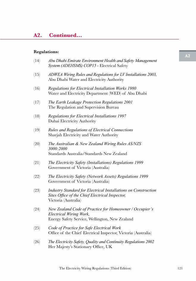
121The Electricity Wiring Regulations (Third Edition)
Regulations:
(14) Abu Dhabi Emirate Environment Health and Safety Management System (ADEHSMS) COP15 - Electrical Safety
(15) ADWEA Wiring Rules and Regulations for LV Installations 2003, Abu Dhabi Water and Electricity Authority
(16) Regulations for Electrical Installation Works 1980 Water and Electricity Department (WED) of Abu Dhabi
(17) The Earth Leakage Protection Regulations 2001 The Regulation and Supervision Bureau
(18) Regulations for Electrical Installations 1997 Dubai Electricity Authority
(19) Rules and Regulations of Electrical Connections Sharjah Electricity and Water Authority
(20) The Australian & New Zealand Wiring Rules AS/NZS 3000:2000 Standards Australia/Standards New Zealand
(21) The Electricity Safety (Installations) Regulations 1999 Government of Victoria (Australia)
(22) The Electricity Safety (Network Assets) Regulations 1999 Government of Victoria (Australia)
(23) Industry Standard for Electrical Installations on Construction Sites Office of the Chief Electrical Inspector, Victoria (Australia)
(24) New Zealand Code of Practice for Homeowner / Occupier’s Electrical Wiring Work, Energy Safety Service, Wellington, New Zealand
(25) Code of Practice for Safe Electrical Work Officeof theChief ElectricalInspector,Victoria(Australia)
(26) The Electricity Safety, Quality and Continuity Regulations 2002 HerMajesty’sStationaryOffice,UK
A2
A2. Continued...

122 The Electricity Wiring Regulations (Third Edition)
(27) The Plugs and Sockets etc. (Safety) Regulations 1994 HerMajesty’sStationaryOffice,UK
(28) The Low Voltage Electrical Equipment (Safety) Regulations 1989 (Adoption of the Low Voltage Directive No. 73/23/EEC)HerMajesty’sStationaryOffice,UK
(29) The Electrical Equipment (Safety) Regulations 1994 HerMajesty’sStationaryOffice,UK
Reference Papers:
(30) Cahier Technique no. 172 – Earthing Systems in LV B Lacroix, R Calvas, Schneider Electric
(31) Cahier Technique no. 173 – Earthing Systems Worldwide B Lacroix, R Calvas, Schneider Electric
(32) Neutral Earthing in LV Networks A Robert, J Hoeffelman, CIRED Conference June 2001
(33) Plugs and Sockets Around the World Conrad H. McGregor, World Standards
(34) The Distribution Code – Annex 1 – E/R 1 – Limits for Harmonics in the Electricity Supply System Approved by the Regulation and Supervision Bureau
(35) The Distribution Code – Annex 1 – E/R 7 – Limits for Voltage Fluctuations in the Electricity Supply System Approved by the Regulation and Supervision Bureau
(36) The Distribution Code – Annex 1 – E/R 10 – Limits for Voltage Unbalance in the Electricity Supply System Approved by the Regulation and Supervision Bureau
(37) Designing for Low Resistance Grounding Lightning Eliminators & Consultants, Inc
(38) Guide to the Installation of Photovoltaic Systems MicrogenerationCertificationScheme(‘MCS’)
A2
A2. Continued...

123The Electricity Wiring Regulations (Third Edition)
The standards listed below are for typical components used in an Electrical Installation. However, this list is not exhaustive and the latest relevant BS or IEC standards should be used.
A3
A3. Reference standards
Components BS IEC
Cables Power & lighting (70˚C PVC,
thermoplastic)6004 502
Power and lighting (90˚C rubber, thermosetting)
50525-1:2011*, 50525-2-41:2011*, 50525-2-42:2011*,
7889 Mineral insulated (copper-clad) 6207, 60702-1* 702
Flexible cables & cords (domestic)
6500, 50525-1:2011*, 50525-2-11:2011*, 50525-2-12:2011*, 50525-2-21:2011*, 50525-2-71:2011*
227
Flexible cables & cords (industrial)
50525-1:2011*, 50525-2-11:2011*, 50525-2-21:2011*, 50525-2-51:2011*, 50525-2-83:2011*, 50525-3-21:2011*
245
Low smoke (90˚C rubber, thermosetting)
7846, 7211, 6724, 7629
Armoured cables (90˚C rubber, thermosetting)
5467
Switchgear and control wiring 6231 Flexible cables for lifts 50214* Cable glands 6121 Crimp connectors 61238* Cable cleats 61914*
Conduits & trunking
Steel 4568, 60423*, 61386-21 50086*, 31 423, 614
PVC 4607 Flexible steel 61386-23
Cable tray 61537*
Trunking 4678

124 The Electricity Wiring Regulations (Third Edition)
A3
A3. Continued...
Components BS IEC
Electrical Accessories General 5733 Ceiling roses 67
Cooker Control Units 4177 Household Appliances 60335* Plugs & socket-outlets (domestic) 546, 1363, 4573 Plugs & socket-outlets (industrial) 60309* Switches (domestic) 60669* Lighting 60598* Emergency lighting 5266 Signs and discharge lighting 559 Isolating (safety) transformers 61558*
LV switchgear & assemblies General 61439* 61439 Contactors & motor starters 60947* 947 Circuit-Breakers (MCB, MCCB) 60898* 898
Circuit-Breakers (RCD, RCBO) 61008*, 61009* 1008, 755
Fuses 88, 60269* 269 Busbar trunking systems 61439-6* 61439-6
General Fire / combustibility test 60695- 4* Degrees of protection & ingress 60529* 529 Assemblies for construction sites 4363 364-7-704 Hazardous areas 60079* Lightning protection 62305*
Earthing7430, 951, 4444, 6701
364-5-54
Wiring diagram symbols 60617* Identification and marking of the
man-machine interface60446*
RCD socket-outlets 7288

125The Electricity Wiring Regulations (Third Edition)
A3
A3. Continued...
Components BS IEC
Solar PV system Thin-film terrestrial photovoltaic PV
modules61646* 61646
Crystalline silicon terrestrial PV modules
61215* 61215
Solar PV modules safety qualification
61730-1* 61730-2*
61730-1, 61730-2
Solar PV inverters degree of protection
60529* 60529
Solar PV inverters protection class 60664-1* 60664-1 Solar PV inverters characteristics of
the utility interface61727
Solar PV inverters EMC Conformance
61000-6-1, 61000-6-2, 61000-6-3, 61000-6-4
Solar PV inverters Harmonics Conformance
61000-3-2, 61000-3-3,
61000-3-11, 61000-3-12
Solar PV inverters power converting equipment safety
62109* 62109
Solar PV d.c. cable See Note 4 See Note 4 Solar PV d.c. connectors 50521* RCD Type B 62423* 62423
Note 1: British Standards marked with an asterix * are also issued as European Standards under the same number (labelled as BS EN).
Note 2: for compliance requirements under the Regulations see clause 3.1.2 and 3.1.4.
Note 3: reference standards for capacitors are given under Regulation 10.2.
Note 4: for solar d.c. cables the following standards may be referenced UL 4703, TUV 2 PfG 1169/08.2007, VDE E PV 01:2008-02 and BS EN 50618 (when published).

126 The Electricity Wiring Regulations (Third Edition)
British Standards are issued by the British Standards Institute (BSI), a UKNationalStandardsbody.TheUKWiringRegulations(BS7671)are published jointly by BSI and the IET (formerly known as the IEE). The BSI represents UK international standards work through theBritish Electrotechnical Committee (BEC) which is a member of the International Electrotechnical Commission (IEC) and also a member of the European Committee for Electrotechnical Standardisation (CENELEC). There are 24 member countries of CENLEC (formed in 1973) whose role is to prepare standards for the European market. CENELEC issues ‘EN’ standardswhichareadoptedby themembercountries, and ‘HD’ standards which are adopted in their generaltechnical content by member countries. The IEC (formed in 1906) has 48 member countries and IEC standards may be adopted voluntarily by any country.
A3
A3. Continued...

127The Electricity Wiring Regulations (Third Edition)
The Electricity Wiring Regulations are effective from 1 January 2008. For any Electrical Installations which were constructed prior to this date, the following Regulations do not apply.
A4(a)
A4(a) List of regulations and clauses which do not apply to existing Electrical Installations
Clause or Regulation Reason Application
Clause 3.1.4 Installation components to meet international standards
Does not apply (see also Clause 3.3.3 referring to repairs to existing installations)
Clause 3.5.6 Clause 5.3.4 Clause 5.5.1
Requirement for Earth Leakage Protection (ELP) and Earthed Equipotential Bonding (EEB)
Does not apply
Clause 4.2.9 Emergency lighting in Electricity Intake rooms
Does not apply
Clause 7.1.1 Prohibition of BS 546 plugs and socket-outlets in domestic premised
Does not apply but it is recommended to replace BS 546 socket-outlets with BS 1363 type
Clause 7.8.6 All Final Distribution Boards must, be arranged so as to provide for at least two zones of ELP
Does not apply if a single RCD of residual operating current 30 mA is fitted to cover the whole DB, or a RCD of residual operating current of 100 mA is fitted to cover the whole DB and 30 mA RCBOs fitted in the DB for all bathrooms and socket-outlet circuits. Otherwise this Regulation shall apply after 1 January 2015, or the date of the next inspection or re-certification, whichever is the earlier
Note: for the avoidance of doubt, for any Electrical Installations constructed before 1 January 2008, Clause 7.8.6 (Regulation 7.8) shall apply after 1 January 2015, or the date of the next inspection or re-certification (which ever is the earlier), unless the conditions in the above table are satisfied.
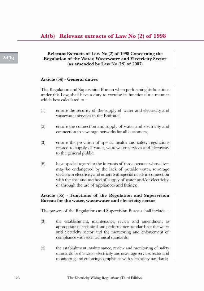
128 The Electricity Wiring Regulations (Third Edition)
Relevant Extracts of Law No (2) of 1998 Concerning the Regulation of the Water, Wastewater and Electricity Sector
(as amended by Law No (19) of 2007)
Article (54) - General duties
The Regulation and Supervision Bureau when performing its functions under this Law, shall have a duty to exercise its functions in a manner which best calculated to –
(1) ensure the security of the supply of water and electricity and wastewater services in the Emirate;
(2) ensure the connection and supply of water and electricity and connection to sewerage networks for all customers;
(3) ensure the provision of special health and safety regulations related to supply of water, wastewater services and electricity to the general public;
(6) have special regard to the interests of those persons whose lives may be endangered by the lack of potable water, sewerage services or electricity and others with special needs in connection with the cost and method of supply of water and/or electricity, orthroughtheuseof appliancesandfittings;
Article (55) - Functions of the Regulation and Supervision Bureau for the water, wastewater and electricity sector
The powers of the Regulations and Supervision Bureau shall include –
(3) the establishment, maintenance, review and amendment as appropriate of technical and performance standards for the water and electricity sector and the monitoring and enforcement of compliance with such technical standards;
(4) the establishment, maintenance, review and monitoring of safety standards for the water, electricity and sewerage services sector and monitoring and enforcing compliance with such safety standards;
A4(b)
A4(b) Relevant extracts of Law No (2) of 1998
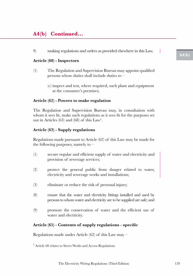
129The Electricity Wiring Regulations (Third Edition)
9) making regulations and orders as provided elsewhere in this Law.
Article (60) - Inspectors
(1) TheRegulationandSupervisionBureaumayappointqualifiedpersons whose duties shall include duties to –
(c) inspect and test, where required, such plant and equipment at the consumer’s premises;
Article (62) - Powers to make regulation
The Regulation and Supervision Bureau may, in consultation with whomitseesfit,makesuchregulationsasitseesfitforthepurposessetout in Articles (63) and (68) of this Law¹.
Article (63) - Supply regulations
Regulations made pursuant to Article (62) of this Law may be made for the following purposes, namely to –
(1) secureregularandefficientsupplyof waterandelectricityandprovision of sewerage services;
(2) protect the general public from danger related to water, electricity and sewerage works and installations;
(3) eliminate or reduce the risk of personal injury;
(8) ensure that thewater and electricity fittings installed and used bypersons to whom water and electricity are to be supplied are safe; and
(9) promote the conservation of water and the efficient use of water and electricity.
Article(65)-Contentsof supplyregulations-specific
Regulations made under Article (62) of this Law may –
A4(b)
A4(b) Continued...
1 Article 68 relates to Street Works and Access Regulations

130 The Electricity Wiring Regulations (Third Edition)
(1) prohibittransmissionorsupplyinspecifiedcircumstances;
(2) require notification of accidents, failures of supply and/ortransmission or distribution facilities and/or when sewerage services are provided;
(3) require plans, maps etc to be kept and made available for inspection and copying;
(4) relieve the Abu Dhabi Water and Electricity Company and
classesof licensedoperatorsspecified in theregulations fromobligations to supply water, electricity or sewerage services in specifiedcircumstances;
(5) require compliance with notices served by the Regulation and Supervision Bureau which – are intended to prevent or end a breach of regulations made under Chapter Three of Part Four of this Law; or eliminate/reduce risk of personal injury or property damage or interference with property;
(6) provide for deemed compliance with technical standards and requirements;
(7) provide for exemptions from the requirements of regulations made under Chapter Three of Part Four of this Law;
(8) restrict or require the use of certain, products, substances or processes or forbid unapproved substances, products and processes;
(9) require substances, products and processes to comply with standards or other requirements established by the regulations;
(10) provide for certain persons/organisations to give approvals required by the regulations and for such approvals to be subject toconditionsormodificationandrevocation;
(11) require the provision of information to prescribed persons;
(13) forbid theuseor installationof fittingswhichhavenotbeenapproved;
A4(b)
A4(b) Continued...

131The Electricity Wiring Regulations (Third Edition)
(14) require water, electricity and wastewater fittings to be of aprescribed size, nature, strength and workmanship;
(15) impose requirements as to installation, arrangement, connection, testing, disconnection, alteration and repair;
(16) impose requirements regarding earthing of electrical installations, electrical voltage and frequency; and
(17) enable the Regulation and Supervision Bureau to authorise any departures from the regulations as may be required and to make those departures subject to conditions.
Article (66) - Failure to comply with regulations
Failure of any person to comply with regulations made under Article (62) of thisLaw shall bepunishedwith afineof not less thanAED250,000.Incasethesamefailureisrepeatedbysuchperson,thefineisdoubled.
Article (67) - Regulations disputes
The court with the appropriate jurisdiction shall hear disputes relating to regulations made under Article (62) of this Law.
Article(106)-Dutytoenforcebyfinalorder
Subject to Article (107) of this Law, where the Regulation and SupervisionBureauissatisfiedthatalicensedoperatoriscontraveningor is likely to contravene any condition of its licence, the Regulation and SupervisionBureaushallassoonaspracticablebyafinalordermakesuch provision as appears to the Regulation and Supervision Bureau to be requisite so as to secure compliance with that condition.
Article(114)-Powertofine
Afinalordermayincludearequirementonthelicenceholdertopaya fine of such amount, being not less than Dirhams 50,000, as theRegulation and Supervision Bureau determines to be appropriate.
A4(b)
A4(b) Continued...

132 The Electricity Wiring Regulations (Third Edition)
A5(a)
A5(a) Distribution Company Earthed System (TN-S)
L1
L2
L3
N
E
Distribution Network
Conductors
Distribution Company
Transformer
TransformerNeutral Point Earth
Main EarthTerminal
Earth sheath or armour ofDistribution Company Cable
is connected toCustomers Installation
Earth fault current
Earth fault currentthrough Distribution
Company cable
Customer’sMain
DistributionBoard
Earth fault in Appliance
A
A
[ see Regulation 6.2 ]

133The Electricity Wiring Regulations (Third Edition)
A5(b)
L1
L2
L3
N
E
A
A
Insulated cablegland
Earth sheath or armour ofDistribution Company Cable
not connected toCustomers Installation
Earth fault current
Earth fault in Appliance
Distribution Network
Conductors
Distribution Company
Transformer
Earth fault currentthrough ground / soil
TransformerNeutral Point Earth
Customer’s Earth Electrode
Main EarthTerminal
Customer’sMain
DistributionBoard
A5(b) Locally Earthed System (TT)
[ see Regulation 6.2 ]

134 The Electricity Wiring Regulations (Third Edition)
A5(c)
A5(c) Distribution Company Earthed System with Locally Earthed System (TN-S and TT)
L1
L2
L3
N
E
Earth fault current
Earth fault current
Earth fault in Appliance
Distribution Network
Conductors
Distribution Company
Transformer
Earth fault currentshared between Customer Earth Electrode andDistribution
Company Earth
Earth sheath or armour ofDistribution Company Cable
is connected toCustomers Installation
TransformerNeutral Point Earth
Customer’s Earth Electrode
Main EarthTerminal
Customer’sMain
DistributionBoard
A
A
[ see Regulation 6.2 ]

135The Electricity Wiring Regulations (Third Edition)
A5(d)
A5(d) Earth Electrode pit and standard labels
SAFETY EARTH CONNECTIONDO NOT REMOVE
SAFETY EARTH BONDINGDO NOT REMOVE
Main Earth Conductor inmetallic conduit 300 x 300mm
Inspection cover
Standard safety label for Main Earth Connections
Standard safety label for main and supplementary bonding connections
[ see clauses 5.5.11, 6.4.3 and 6.5.6 ]

136 The Electricity Wiring Regulations (Third Edition)
A5(e)
A5(e) Main Earth Terminal (MET) at Main Distribution Board (MDB)
CircuitEarth Conductors
for sub-mainCircuits
DistributionCompany
Earth
Main Circuit Breaker
To SMDB 2
To SMDB 1
MET Neutral Bar
Earth connectionto metal door
CEC
Distribution Company Earth
MEC to Owner Earth Electrode
Test Link
DISTRIBUTION COMPANY EARTH
CUSTOMER EARTH ELECTRODE
DB2 MAIN EARTHCONDUCTOR
Earth conductor labels at MET A
A
B
B
DB1 MAIN EARTHCONDUCTOR
Note 1: illustration shows a Distribution Company Earthed System with a Locally Earthed System (TN-S and TT).
Note 2: for sizing of Earth Conductors refer to Appendix A5(j) (S for cables up to 16 mm2, 16 mm2 for cables up to 35 mm2 and S above this).
Note 3: this arrangement shows single core cables for SMDBs, other arrangement may be used (e.g. cables with SWA with seperate Earth Conductor).
2
[ see Regulations 6.2 and 6.3 ]

137The Electricity Wiring Regulations (Third Edition)
FinalDistribution
Board
MainDistribution
Board
Main EarthConductor to
Earth Electrode
Main EarthTerminal Functional Earth
(see clause 6.9.2)
CEC in applianceflexible cord
CEC in metal orplastic conduit
Distribution Company Earth
CEC to fixed Appliance
CEC to switches andAccessories
Earth Bar
MEC
CEC
CEC
CEC
A5(f)
A5(f) Main Earth Conductors (MEC) and Circuit Earth Conductors (CEC)
Note 1: common terminology (outside these Regulations) includes CPC (Circuit Protective Conductor) and ECC (Earth Continuity Conductor ) in place of CEC illustrated above. [ see Regulation 6.2 ]
Note 2: for sizing of Earth Conductors refer to Appendix A5(j) (S for cables up to 16 mm2, 16 mm2 for cables up to 35 mm2 and S above this). 2

138 The Electricity Wiring Regulations (Third Edition)
A5(g)
A5(g) Components of Earth Fault Loop Impedance
X
Internal Earth Loop Impedance
Source Earth Loop Impedance, Ze
Impedance of Circuit phase conductor1
Resistance of fault2
2
Impedance of Circuit Earth Conductor (CEC)3
3
Impedance of Local Earth Electrode and Main Earth Conductor 4
4
Impedance of fault path through Earth5
Impedance of transformer Earth Electrode and Earth Conductor to the transformer star point
6
Impedance of network cable Earth Conductor / armouring 8
Distribution Company transformer winding9
Live conductor of distribution network cable10
10
Live conductor of supply cable
Note: Sub Main Distribution board is omitted for clarity.
11
7 Impedance of supply cable Earth Conductor / armouring
Distribution CompanyTransformer
Transformer NeutralPoint Earth
METMain EarthTerminal
Electricity Intake Circuit Breaker
Earth fault in Appliance
L
N
E
8
5 1
7
6 11
9 L1 L2 L3
N E
Distribution Network
Conductors
[ see Regulation 6.7 ]
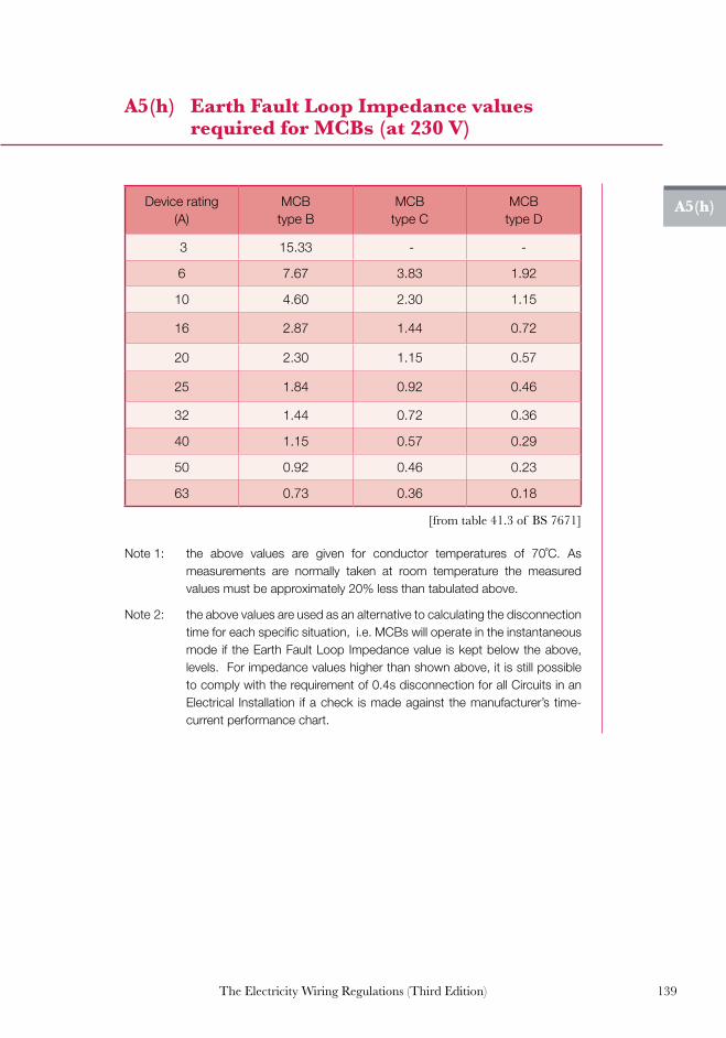
139The Electricity Wiring Regulations (Third Edition)
A5(h)
A5(h) Earth Fault Loop Impedance values required for MCBs (at 230 V)
Device rating(A)
MCB type B
MCB type C
MCB type D
3 15.33 - -
6 7.67 3.83 1.92
10 4.60 2.30 1.15
16 2.87 1.44 0.72
20 2.30 1.15 0.57
25 1.84 0.92 0.46
32 1.44 0.72 0.36
40 1.15 0.57 0.29
50 0.92 0.46 0.23
63 0.73 0.36 0.18
[from table 41.3 of BS 7671]
Note 1: the above values are given for conductor temperatures of 70˚C. As measurements are normally taken at room temperature the measured values must be approximately 20% less than tabulated above.
Note 2: the above values are used as an alternative to calculating the disconnection time for each specific situation, i.e. MCBs will operate in the instantaneous mode if the Earth Fault Loop Impedance value is kept below the above, levels. For impedance values higher than shown above, it is still possible to comply with the requirement of 0.4s disconnection for all Circuits in an Electrical Installation if a check is made against the manufacturer’s time-current performance chart.

140 The Electricity Wiring Regulations (Third Edition)
A5(i)
A5(i) Resistance per metre of copper conductors
Conductor cross-sectional area (mm²)
Resistance per metre (milli-ohms)
1.0 18.1
1.5 12.1
2.5 7.41
4.0 4.61
6.0 3.08
10.0 1.83
16.0 1.15
25.0 0.73
Note: to allow for the increase in resistance with increased temperature under fault conditions these values must be multiplied by 1.2 for PVC insulated cables.
[above values at 20˚C]

141The Electricity Wiring Regulations (Third Edition)
A5(j)
A5(j) Sizing of Earth Conductors and Equipotential Bonding Conductors
Cross sectional area of phase and neutral
conductors (S) (mm2)
Minimum cross-sectional area of Earth
conductors [see note 1]
(mm2)
Minimum cross-sectional area of
equipotential bonding conductors
(mm2)
S <= 16S
(not less than 1.5 see note 2)
S / 2 (not less than 4 or
6, see note 3)
16 < S <= 35 16 10
S > 35 S / 2S / 4
(but not exceeding 25)
[from table 54.7 of BS 7671]
Note 1: for Main Earth Conductors between Earth Electrodes and the Main Earth Terminal of an Electrical Installation, S should be taken as the cross-sectional area of the conductors of the incoming supply cable. For Circuit Earth Conductors S should be taken as the cross-sectional area of the Circuit phase conductors.
Note 2: Earth Conductors must always be insulated and a cross-sectional area of less than 1.5 mm2 must not be used unless they are an integral part of a sheathed cable (e.g. an Appliance flexible cord).
Note 3: Main Equipotential Bonding Conductors should be sized according to the live conductors of the incoming supply, but should not be less than 6 mm2. Supplementary Bonding Conductors should be sized according to the live conductors of the circuit to which they are connected but should not be less than 4 mm2.
Note 4: as an alternative to using the above selection table, the sizing of Earth Conductors and Equipotential Bonding Conductors may be calculated using the adiabatic equation provided in the IET Wiring Regulations BS 7671:2008 paragraph 543.1.3. This normally allows smaller sizes of Earth Conductor to be used.
For example: 4.0 mm2 earth for 6 mm2 circuit conductor 2.5 mm2 earth for 4 mm2 circuit conductor 1.5 mm2 earth for 2.5 mm2 circuit conductor

142 The Electricity Wiring Regulations (Third Edition)
A5(k)
A5(k) Minimum number of Earth Electrodes
The number of Earth Electrodes required at a Premises will be determined primarily by the value of Earth Resistance that can be achieved from each. However, the minimum number in any case shall be as shown below:
Main incoming circuit-breaker rating (Amps)
Minimum number of Earth
Electrodes
Minimum size of main Earth Conductor (mm2)
60/100 1 16
200 1 50
300 1 50
400 1 70
500 2 70
600 2 70
800 2 70
1000 2 70
1600 2 70
2000 2 150
2500 2 150
Note 1: standard Earth Electrode diameters are 9 mm, 12.5 mm or 15 mm for copper-clad steel, or 16 mm for stainless steel. Standard lengths are 1.2 m or 1.5 m (see also BS 7430).
Note 2: structural foundations of large buildings may be used as Earth Electrodes, see clause 6.4.8 and 6.8.4.
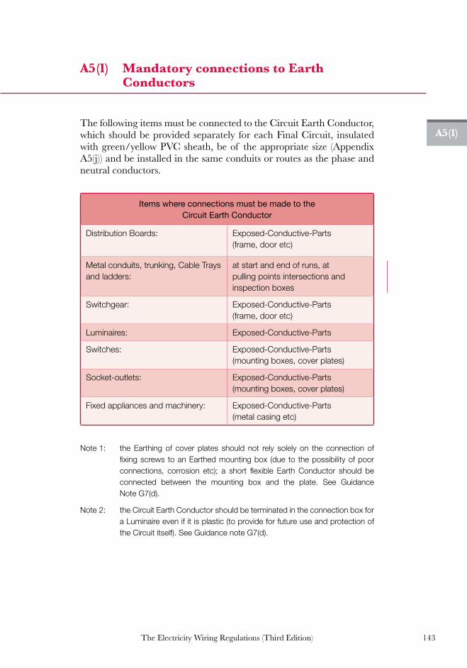
143The Electricity Wiring Regulations (Third Edition)
A5(l)
A5(l) Mandatory connections to Earth Conductors
The following items must be connected to the Circuit Earth Conductor, which should be provided separately for each Final Circuit, insulated with green/yellow PVC sheath, be of the appropriate size (Appendix A5(j)) and be installed in the same conduits or routes as the phase and neutral conductors.
Items where connections must be made to the Circuit Earth Conductor
Distribution Boards: Exposed-Conductive-Parts (frame, door etc)
Metal conduits, trunking, Cable Trays and ladders:
at start and end of runs, at pulling points intersections and inspection boxes
Switchgear: Exposed-Conductive-Parts (frame, door etc)
Luminaires: Exposed-Conductive-Parts
Switches: Exposed-Conductive-Parts (mounting boxes, cover plates)
Socket-outlets: Exposed-Conductive-Parts (mounting boxes, cover plates)
Fixed appliances and machinery: Exposed-Conductive-Parts (metal casing etc)
Note 1: the Earthing of cover plates should not rely solely on the connection of fixing screws to an Earthed mounting box (due to the possibility of poor connections, corrosion etc); a short flexible Earth Conductor should be connected between the mounting box and the plate. See Guidance Note G7(d).
Note 2: the Circuit Earth Conductor should be terminated in the connection box for a Luminaire even if it is plastic (to provide for future use and protection of the Circuit itself). See Guidance note G7(d).

144 The Electricity Wiring Regulations (Third Edition)
A5(m)
A5(m) Residual operating current settings for RCDs and ELP devices
Equipment Maximum Residual operating current settings (mA)
13 A switched-socket outlets 30
Water heaters 30
Kitchen fixed Appliances (e.g. washing machine)
30
Domestic water pumps 30
Swimming pool pumps, or jacuzzi 30
Underwater lighting SELV only
General fixed lighting (except in bathrooms and swimming pools)
100
Floodlighting 100 - 300
Window or split type air-conditioning 100
Air handling, a/c fan coils etc 100
Central or package a/c units 100 - 300
Irrigation pump 100
Electric Cooker 30
Industrial machines etc 100 - 300
Elevators, escalators, lifts 300 - 500
Neon signs 300
School areas (e.g. laboratory for children)
10
LV main circuit breakers or switchboards (Electricity Intake)
See Note 4
Note 1: where two values are indicated, the higher value is allowed only where the equipment is not normally accessible to any person.
Note 2: all Final Circuits in a bathroom (including lighting, but excluding FCUs in a ceiling void) must be provided with 30 mA RCD protection. See clause 9.3.2(a).

145The Electricity Wiring Regulations (Third Edition)
A5(m)Note 3: where a Circuit supplies more than one type of equipment, the lower value
must be used for RCD protection (e.g. a Circuit supplying bedroom lighting and bathroom lighting must be protected by a 30 mA RCD).
Note 4: the selection of ELP devices at main switchboards must take into account the requirement for discrimination with downstream Protective Devices (clause 5.4.5 and 5.4.6). For small supplies (200A or less), a 300 mA RCD device may be used, with time delay of 200 ms. For larger supplies (above 200A), Earth Leakage Protection relays may be used in conjunction with MCCBs or ACBs incorporating a trip unit (e.g. 1A, 3A, 5A with a suitable time delay to ensure proper discrimination with downstream Protective Devices). Irrespective of the Earth Leakage Protection provided at the main switchboard, the incomer MCCB or ACB shall have short-circuit protection to ensure tripping within 400 ms taking into account the Earth Fault Loop Impedance.
The table opposite shows the required residual operating current values for RCDs and other Earth Leakage Protection devices. These are intended to provide supplementary protection of electric shock as well as protection against high resistance earth faults which may not operate overcurrent devices and pose a risk of overheating or fire, see Regulation 5.4.
All Final Circuits where Appliances may be used by any person must be provided with Earth Leakage Protection. Earth Leakage Protection must also be provided at the main Electricity Intake and subsequent Distribution Boards where necessary, see Regulation 5.4.
A5(m) Continued...

146 The Electricity Wiring Regulations (Third Edition)
A6(a)
A6(a) Time-current characteristic of MCBs as multiple of rated current
SHORT CIRCUIT CURRENT AS A MULTIPLE OF RATED CURRENT
2 HRS
1 HR
1,000
100
10
1.0
0.1
0.01
Type B
Type C
Type D
0.001 1 3 5 10 20 100 1,000
OP
ER
AT
ING
TIM
E IN
SE
CO
ND
S
Reproduced with permission of Crabtree / Electrium Ltd.
[ see notes to A6(f) ]

147The Electricity Wiring Regulations (Third Edition)
A6(b)
A6(
b)
Tim
e-cu
rren
t ch
arac
teri
stic
of
Typ
e B
MC
Bs
Current
Rating
Current fo
r tim
e 0.1 sec to 5 se
cs
Tim
e / current ch
aracteris
tics for Typ
e B
circuit-b
reak
ers to BS
EN 60
898
and RCBO
s to BS
EN 61
009
30 A
50 A
80 A
100 A
125 A
160 A
200 A
250 A
315 A
400 A
500 A
625 A
125 A
100 A
80 A
63 A
50 A
40 A
32 A
25 A
20 A
16 A
10 A
6 A
[ fro
m fi
g. 3A
4 of
BS 76
71 ]
TIME, SECONDS
PR
OS
PE
CT
IVE
CU
RR
EN
T, r
.m.s
. AM
PE
RE
S
10 0
00
1000
100 10
10
100
1 00
0 10
000
For p
rosp
ectiv
e fault c
urrents i
n ex
cess
of th
ose
prov
idin
g in
stan
tane
ous o
pera
tion
refe
r to
the
man
ufac
ture
r’s le
t-thr
ough
ene
rgy
data
.
1
1
0.1
0.01
6A
10 A
16 A
20 A
25 A
32 A
40 A
50 A
63 A
80 A
100 A
125 A

148 The Electricity Wiring Regulations (Third Edition)
A6(
d)
Tim
e-cu
rren
t ch
arac
teri
stic
of
Typ
e D
MC
Bs
A6(c)
A6(
c)
Tim
e-cu
rren
t ch
arac
teri
stic
of
Typ
e C
MC
Bs
[ fro
m fi
g. 3A
5 of
BS 76
71 ]
TIME, SECONDS
PR
OS
PE
CT
IVE
CU
RR
EN
T, r
.m.s
. AM
PE
RE
S
10 0
00
1000 10
0 10
1010
01
000
10 0
00
For p
rosp
ectiv
e fault c
urrents i
n ex
cess
of th
ose
prov
idin
g in
stan
tane
ous o
pera
tion
refe
r to
the
man
ufac
ture
r’s le
t-thr
ough
ene
rgy
data
.
1
1
0.1
0.01
Current
Rating
Current fo
r tim
e 0.1 sec to 5 se
cs
Tim
e / c
urre
nt ch
arac
teris
tics f
or T
ype
Cci
rcui
t-bre
aker
s to
BS E
N 60
898
and
RCBO
s to
BS E
N 61
009
60 A
100 A
160 A
200 A
250 A
320 A
400 A
500 A
630 A
800 A
1000 A
1250 A
125 A
100 A
80 A
63 A
50 A
40 A
32 A
25 A
20 A
16 A
10 A6 A
6A
10 A
16 A
20 A
25 A
32 A
40 A
50 A
63 A
80 A
100 A
125 A

149The Electricity Wiring Regulations (Third Edition)
A6(d)
A6(
d)
Tim
e-cu
rren
t ch
arac
teri
stic
of
Typ
e D
MC
Bs
[ fro
m fi
g. 3A
6 of
BS 76
71 ]
TIME, SECONDS
PR
OS
PE
CT
IVE
CU
RR
EN
T, r
.m.s
. AM
PE
RE
S
10 0
00
1000
100 10
10
100
1 00
0 10
000
For p
rosp
ectiv
e fault c
urrents i
n ex
cess
of th
ose
prov
idin
g in
stan
tane
ous o
pera
tion
refe
r to
the
man
ufac
ture
r’s le
t-thr
ough
ene
rgy
data
.
1
1
0.1
0.01
Current
Rating
Current fo
r tim
e 0.1 sec to 5 se
cs
Tim
e / c
urre
nt ch
arac
teris
tics f
or T
ype
D
circ
uit-b
reak
ers t
o BS
EN
6089
8 an
d R
CBO
s to
BS E
N 61
009
120 A
200 A
320 A
400 A
500 A
640 A
800 A
1000
A
1260
A
1600
A
2000
A
2500
A
125 A
100 A
80 A
63 A
50 A
40 A
32 A
25 A
20 A
16 A
10 A
6 A
6A
10 A
16 A
20 A
25 A
32 A
40 A
50 A
63 A
80 A
100 A
125 A

150 The Electricity Wiring Regulations (Third Edition)
A6(e)
A6(e) Typical energy let-through characteristics of MCBs
Reproduced with permission of Crabtree / Electrium Ltd.
PROSPECTIVE FAULT CURRENT (kA)
TO
TA
L L
ET
-TH
RO
UG
H E
NE
RG
Y (
I2 t)
105
1.0mm2
1.5mm2
2.5mm2
CA
BL
E C
ON
DU
CT
OR
SIZ
ES
I2t energy let-through in A2s (50Hz sine wave)
one complete 1/2 cycle
104
6A MCB
10A MCB
16A MCB
20A MCB32A MCB40A MCB
50&63A MCB
0.1 1.0 10 100.0
103
16

151The Electricity Wiring Regulations (Third Edition)
A6(f)
A6(f) MCBs selection criteria
Operating characteristics of MCB types and the required Earth Fault Loop Impedance values are given in Appendix A6(a) to A6(d) and Appendix A5(h). MCBs for common cable sizes and Circuits are shown in the following table:
MCB nominal rating Amps
Cable size mm2
Cable rating at
30˚C, PVC Amps, (kW)
Cable rating at
40˚C, PVC Amps, (kW)
Typical Circuit application
6 1.517.5 (3.4)
15.2 (3.0)
Lighting (light load)
10 2.524.0 (4.7)
20.9 (4.1)
Lighting (heavy load)
16 2.524.0 (4.7)
20.9 (4.1)
Radial Circuit to socket-outlets
20 4.032.0 (6.3)
27.8 (5.4)
Radial Circuit to fixed appliance
32 2 x 4.048
(9.3)41.7(8.1)
Ring Circuit to socket-outlets
32 6.041.0 (8.0)
35.7 (7.0)
Radial Circuit to large Appliance (e.g. cooker)
40 10.057.0 (11.1)
49.6 (9.7)
Radial Circuit to machinery (e.g. chiller unit)
Note 1: cable ratings are taken from Appendix A7(a), assuming one circuit in conduit, with temperature correction factors applied from Appendix A7(g). Power factor of 0.85 is assumed to calculate kW ratings at 230V.
Note 2: selection of MCBs for overload protection of cables must take account of the device characteristics given in Appendix A6(b) to A6(d). These are based on minimum MCB operating currents of 1.45 times the MCB nominal rating (In) and a maximum ‘non-tripping’ current of 1.15 times In. Hence, cables must be selected with ratings at least 1.15 times the MCB nominal rating (see IEE Guidance Note 6 - section 2).

152 The Electricity Wiring Regulations (Third Edition)
A6(f)
A6(f) Continued...
Theclassificationof TypesB,CorDisbasedonthefaultcurrentratingat which magnetic operation occurs and their ability to handle surge currents without tripping. See Appendix A6(a).
• TypeBdevicesaredesignedtotripatfaultcurrentsof 3-5timesrated current (In). For example a 10 A device will trip at 30-50 A
• TypeCdevicesaredesignedtotripat5-10timesIn • TypeDdevicesaredesignedtotripat10-20timesIn
Type B devices are generally suitable for domestic applications. Type C devices are the normal choice for commercial and industrial applications wherelargegroupsof fluorescentlighting,motors,etcareused.
Type D devices have more limited applications, where high inrush currents may be expected. For example, large battery systems, motors, transformers, etc.
Sometimesfailureof tungstenfilamentlampscantripTypeBcircuit-breakers in domestic and retail environments. This is caused by high arcing currents occurring at the time of failure and is generally associated with inferior quality lamps. A Type C device may be substituted for a Type B device where unwanted tripping persists, especially in commercial applications. A change from Type C to Type D devices should only be taken after careful consideration of the installation conditions, in particular the operating times required by Regulation 5.5.
(Referenced from www.voltimum.co.uk)
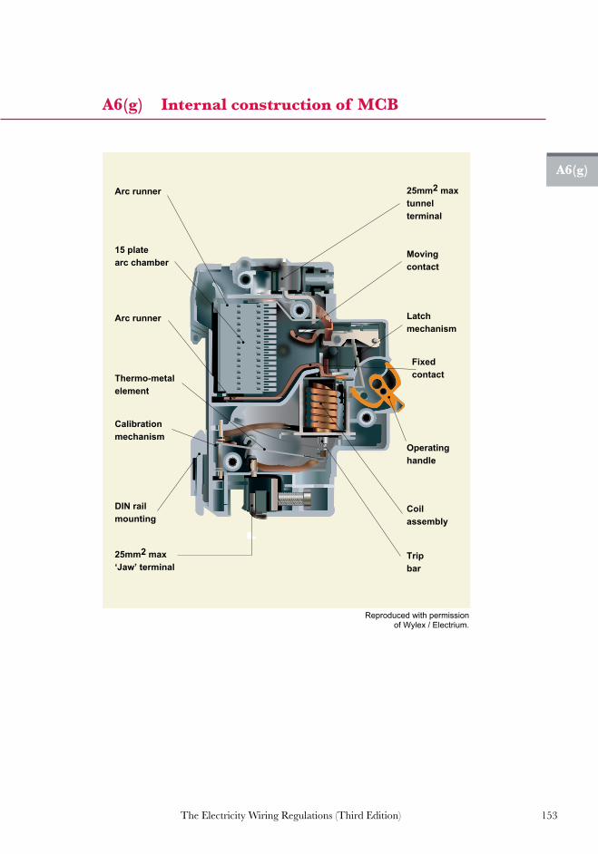
153The Electricity Wiring Regulations (Third Edition)
A6(g)
A6(g) Internal construction of MCB
Arc runner
Arc runner
15 plate arc chamber
Moving contact
Latch mechanism
Fixed contact
Operating handle
Coil assembly
Trip bar
Thermo-metal element
Calibration mechanism
DIN rail mounting
25mm2 max ‘Jaw’ terminal
25mm2 max tunnel terminal
Reproduced with permission of Wylex / Electrium.
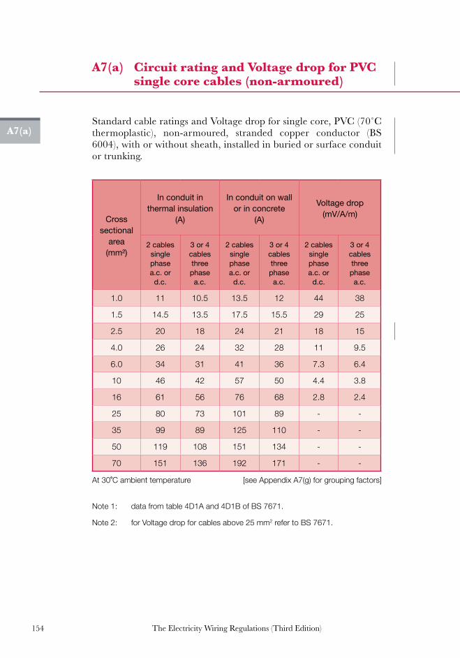
154 The Electricity Wiring Regulations (Third Edition)
A7(a)
A7(a) Circuit rating and Voltage drop for PVC single core cables (non-armoured)
StandardcableratingsandVoltagedropforsinglecore,PVC(70˚Cthermoplastic), non-armoured, stranded copper conductor (BS 6004), with or without sheath, installed in buried or surface conduit or trunking.
Cross sectional
area (mm²)
In conduit in thermal insulation
(A)
In conduit on wall or in concrete
(A)
Voltage drop (mV/A/m)
2 cables single phase a.c. or
d.c.
3 or 4 cables three phase a.c.
2 cables single phase a.c. or
d.c.
3 or 4 cables three phase a.c.
2 cables single phase a.c. or
d.c.
3 or 4 cables three phase a.c.
1.0 11 10.5 13.5 12 44 38
1.5 14.5 13.5 17.5 15.5 29 25
2.5 20 18 24 21 18 15
4.0 26 24 32 28 11 9.5
6.0 34 31 41 36 7.3 6.4
10 46 42 57 50 4.4 3.8
16 61 56 76 68 2.8 2.4
25 80 73 101 89 - -
35 99 89 125 110 - -
50 119 108 151 134 - -
70 151 136 192 171 - -
Note 1: data from table 4D1A and 4D1B of BS 7671.
Note 2: for Voltage drop for cables above 25 mm2 refer to BS 7671.
At 30˚C ambient temperature [see Appendix A7(g) for grouping factors]

155The Electricity Wiring Regulations (Third Edition)
A7(b)
A7(b) Circuit rating and Voltage drop for PVC multi-core cables (non-armoured)
StandardcableratingsandVoltagedropforPVC(70˚Cthermoplastic)multi-core cables (sheathed), non-armoured, stranded copper conductor (BS 6004), installed in buried or surface mounted conduit or trunking, or on exposed, perforated cable tray.
Cross sectional
area (mm²)
In conduit on wall or in concrete
(A)
Clipped direct to a wall
(A)
On perforated Cable Tray or in
free air (A)
2 core single phase a.c. or
d.c.
3 or 4 core three phase a.c.
2 core single phase a.c. or
d.c.
3 or 4 core three phase a.c.
2 core single phase a.c. or
d.c.
3 or 4 core three phase a.c.
1.0 13 11.5 15 13.5 17 14.5
1.5 16.5 15 19.5 17.5 22 18.5
2.5 23 20 27 24 30 25
4 30 27 36 32 40 34
6 38 34 46 41 51 43
10 52 46 63 57 70 60
16 69 62 85 76 94 80
25 90 80 112 96 119 101
35 111 99 138 119 148 126
50 133 118 168 144 180 153
70 168 149 213 184 232 196
95 201 179 258 223 282 238
120 232 206 299 259 328 276
150 258 225 344 299 379 319
At 30˚C ambient temperature [see Appendix A7(g) for grouping factors]
Note 1: data taken from table 4D2A and 4D2B of BS 7671.
Note 2: 2-core refers to single-phase Circuits, 3 or 4-core refers to three-phase Circuits.

156 The Electricity Wiring Regulations (Third Edition)
A7(b)
A7(b) Continued...
Cable size (mm²)
Voltage drop (mV/A/m)
1.0 1.5 2.5 4 6 10 16
2 core single phase a.c. or d.c.
44 29 18 11 7.3 4.4 2.8
3 or 4 core three phase a.c.
38 25 15 9.5 6.4 3.8 2.4
Note: for Voltage drop for cables above 16 mm² refer to BS 7671.

157The Electricity Wiring Regulations (Third Edition)
A7(c)
A7(c) Circuit rating and Voltage drop for PVC multi-core cables (armoured)
Standard cable ratings and Voltage drop for multi-core armoured, PVC (70˚C thermoplastic) cables, stranded copper conductor (BS 5467),installed exposed (clipped to a wall) or on perforated Cable Tray.
Cross sectional
area (mm²)
Clipped direct to a wall
(A)
On perforated Cable Tray
(A)
Voltage drop (mV/A/m)
2 core single phase a.c. or
d.c.
3 or 4 core three phase a.c.
2 core single phase a.c. or
d.c.
3 or 4 core three phase a.c.
2 core single phase a.c. or
d.c.
3 or 4 core three phase a.c.
1.5 21 18 22 19 29 25
2.5 28 25 31 26 18 15
4 38 33 41 35 11 9.5
6 49 42 53 45 7.3 6.4
10 67 58 72 62 4.4 3.8
16 89 77 97 83 2.8 2.4
25 118 102 128 110 - -
35 145 125 157 135 - -
50 175 151 190 163 - -
70 222 192 241 207 - -
95 269 231 291 251 - -
120 310 267 336 290 - -
150 356 306 386 332 - -
185 405 348 439 378 - -
240 476 409 516 445 - -
300 547 469 592 510 - -
Note 1: data taken from table 4D4A and 4D4B of BS 7671.
Note 2: 2 core refers to single-phase Circuits, 3 or 4 core refers to three-phase Circuits.
Note 3: for Voltage drop for cables above 16 mm² refer to BS 7671.
At 30˚C ambient temperature [see Appendix A7(g) for grouping factors]

158 The Electricity Wiring Regulations (Third Edition)
A7(d)
A7(d) Circuit rating and Voltage drop for thermo-setting (XLPE) multi-core cables (armoured)
Standard cable ratings and Voltage drop for multi-core, 90˚Cthermosetting plastic insulated (XLPE), armoured cable, stranded copper conductor (BS 5467 and BS 6724), surface mounted or on Cable Tray.
Cross sectional
area (mm²)
Clipped direct to a wall
(A)
On perforated Cable Tray
(A)
Voltage drop (mV/A/m)
2 core single phase a.c. or d.c.
3 or 4 core three phase a.c.
2 core single phase a.c. or d.c.
3 or 4 core three phase a.c.
2 core single phase a.c. or d.c.
3 or 4 core three phase a.c.
1.5 27 23 29 25 31 27
2.5 36 31 39 33 19 16
4 49 42 52 44 12 10
6 62 53 66 56 7.9 6.8
10 85 73 90 78 4.7 4.0
16 110 94 115 99 2.9 2.5
25 146 124 152 131 - -
35 180 154 188 162 - -
50 219 187 228 197 - -
70 279 238 291 251 - -
95 338 289 354 304 - -
120 392 335 410 353 - -
150 451 386 472 406 - -
185 515 441 539 463 - -
240 607 520 636 546 - -
300 698 599 732 628 - -
Note 1: from table 4E4A and 4E4B of BS 7671 [2 core refers to single-phase Circuits, 3 or 4 core refers to three-phase Circuits].
Note 2: for Voltage drop for cables above 16 mm² refer to BS 7671.
At 30˚C ambient temperature [see Appendix A7(g) for grouping factors]

159The Electricity Wiring Regulations (Third Edition)
A7(e)
A7(e) Circuit rating for MICC cable
Standard cable ratings and Voltage drop for mineral insulated copper-clad cables installed on a wall (clipped direct). PVC sheathed cable assumes 70˚C sheath temperature, bare copper-clad cable assumes105˚Csheathtemperature.
Cro
ss-s
ectio
nal
area
PVC
shea
th (7
0 ˚C)
2
x sin
gle
or tw
in c
ore
cabl
e a.
c. o
r d.c
.
PVC
she
ath
(70 ˚
C)
3 co
re
Bare
she
ath
105˚
C
2 x
sing
le o
r 1
two
core
cab
le, s
ingl
e ph
ase
a.c.
or d
.c.
Bare
she
ath
105˚
C3
x si
ngle
or 1
thre
e co
re, o
r fou
r cor
e ca
ble
(mm²) (A) (A) (A) (A)
Light duty
500 V
1.0 18.5 15 22 19
1.5 23 19 28 24
2.5 31 26 38 33
4 40 35 51 44
Heavy duty
750 V
1 19.5 16 24 20
1.5 25 21 31 26
2.5 34 28 42 35
4 45 37 55 47
6 57 48 70 59
10 77 65 96 81
16 102 86 127 107
25 133 112 166 140
35 163 137 203 171
50 202 169 251 212
Note 1: for MICC cable installed in perforated Cable Tray, the current rating is approximately 5 - 10% greater than shown above, see BS 7671 table 4G1A and 4G2A.
Note 2: where the sheath temperature may be above 70˚C, care should be taken that the cable is not within reach of any person or in contact with combustible materials.
At 30˚C ambient temperature [see Appendix A7(g) for grouping factors]

160 The Electricity Wiring Regulations (Third Edition)
A7(f)
A7(f) Circuit rating and Voltage drop for flexible cords
Standard current ratings and Voltage drop for flexible cords, 60˚Cconductor temperature (PVC or rubber insulated), stranded copper conductors to BS 6500 (domestic applications).
Cross sectional
area
Single phase
Three phase
Voltage drop
(single phase)
Voltage drop (three phase)
Mass supportable
by twin flexible cord
(mm²) (A) (A) (mV/A/m) (mV/A/m) (kg)
0.5 3 3 93 80 2
0.75 6 6 62 54 3
1.0 10 10 46 40 5
1.25 13 - 37 - 5
1.5 16 16 32 27 5
2.5 25 20 19 16 5
4.0 32 25 12 10 5
Forambienttemperaturesabove30˚C,thefollowingcorrectionfactorsmaybeappliedforflexiblecords:
At 30˚C ambient temperature [from table 4H3A of BS 7671]
Ambient temperature (°C) 35 40 45 50 55
Correction factor 0.91 0.82 0.71 0.58 0.41

161The Electricity Wiring Regulations (Third Edition)
A7(g)
A7(g) Rating factors with respect to ambient (air) temperature
Ambient temperature correction factors (relative to 30°C) for cable ratings shown in Appendices A7(a) to A7(e).
Type of cable insulation
Ambient
temperature (°C)
70°C PVC
thermo-plastic
90°C Rubber or XLPE
thermosetting
mineral insulated
(70°C sheath)
mineral insulated (105°C sheath)
25 1.03 1.02 1.07 1.04
30 1.00 1.00 1.00 1.00
35 0.94 0.96 0.93 0.96
40 0.87 0.91 0.85 0.92
45 0.79 0.87 0.78 0.88
50 0.71 0.82 0.67 0.84
55 0.61 0.76 0.57 0.80
60 0.50 0.71 0.45 0.75
[from table 4B1 of BS7671:2008]

162 The Electricity Wiring Regulations (Third Edition)
A7(h)
A7(h) Rating factors with respect to grouping of cables
Because of mutual heating effects, the following correction factors should be applied to the tables in Appendix A7(a) to A7(e) for situations where a number of cables are installed close together. These factors assume all cables are fully loaded; however, if an individual cable is loaded below 30% of its rating it may be excluded from the total number in the group.
Method of installation
Number of cables
Enclosed in conduit (surface or buried) or bunched on a non-metallic surface
Single layer, clipped to a non-metallic surface (wall
or floor)
Single layer multi-
core on a perforated Cable Tray
Single layer multi-core on cable ladder
system or cleats
2 0.80 0.85 0.88 0.87
3 0.70 0.79 0.82 0.82
4 0.65 0.75 0.77 0.80
5 0.60 0.73 0.75 0.80
6 0.57 0.72 0.73 0.79
7 0.54 0.72 0.73 0.79
8 0.52 0.71 0.72 0.78
9 0.50 0.70 0.72 0.78
12 0.45 0.70 0.72 0.78
16 0.41 0.70 0.72 0.78
20 0.38 0.70 0.72 0.78
[taken from table 4C1 of BS 7671]
Note 1: these factors are applicable to uniform groups of cable, equally loaded.
Note 2: where horizontal clearances between adjacent cables exceed twice their overall diameter, no rating factor need to be applied.
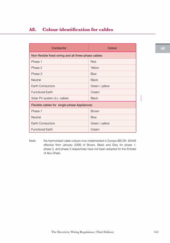
163The Electricity Wiring Regulations (Third Edition)
A8
A8. Colour identification for cables
Conductor Colour
Non-flexible fixed wiring and all three-phase cables:
Phase 1 Red
Phase 2 Yellow
Phase 3 Blue
Neutral Black
Earth Conductors Green / yellow
Functional Earth Cream
Solar PV system d.c. cables Black
Flexible cables for single-phase Appliances:
Phase 1 Brown
Neutral Blue
Earth Conductors Green / yellow
Functional Earth Cream
Note: the harmonised cable colours now implemented in Europe (BS EN 60446 effective from January 2006) of Brown, Black and Grey for phase 1, phase 2, and phase 3 respectively have not been adopted for the Emirate of Abu Dhabi.

164 The Electricity Wiring Regulations (Third Edition)
A9
A9. Capacity of conduits, trunking and Cable Trays
Conductor ( mm2 )
Diameter of Conduit (mm)
20 25 32
Maximum number of conductors
1.5 7 12 -
2.5 5 9 12
4.0 3 6 9
6.0 - 5 8
10.0 - 3 6
16.0 - - 4
25.0 - - 3
Note 1: for Cable Trunking, the space factor (total cross-sectional area of cables compared with the interior cross-sectional area of trunking) must not exceed 50%. Trunking is sized by multiplying the number of cables by the cable factor for each cable, applying the space factor to determine the capacity required. The appropriate trunking is then selected from the capacity chart published by the manufacturers.
Note 2: for Cable Trays, the sum of the combined diameter of all cables installed on the tray shall not exceed 60% of the internal Cable Tray width. Where cables are spaced on the Cable Tray, this can be used as part of the space factor.

165The Electricity Wiring Regulations (Third Edition)
A10
A10. IP coding for ingress protection
Ingress protection: IP codes
First digit: protection against ingress by solid objects
Second digit: protection against ingress of water
X Not tested or not applicable X Not tested or not applicable
0 No protection 0 No protection
1 Human hand or objects > 50mm
1 Vertically falling water
2 Human finger or objects > 12mm
2 Sprays of water < 15˚ from vertical
3 Objects > 2.5mm (e.g. tools or wires)
3 Sprays of water < 60˚ from vertical
4 Objects > 1.0mm (e.g. small wires)
4 Splashes of water (from any direction)
5 Limited protection against dust (to the extent that does not harm the equipment or impair safety)
5 Low pressure jets of water (from any direction)
6 Totally protected against dust6 Strong jets of water (from
any direction)
7 Temporary immersion
8 Total immersion
TheIPcodingsystemisspecifiedinBSEN60529:1992(adoptedfromIEC529:1989).Thefirstdigit specifiesprotectionagainst ingressof foreignobjectsof varyingsize,rangingfromhumanhandsorfingerstofinedustparticles.Theseconddigitspecifiesprotectionagainstingressof water, ranging from free falling water, to immersion in water.
BS EN 60529 does not specify protection against the risk of explosion, humidity or corrosive gases. If enclosures of equipment are drilled or knockouts removed, suitable measures should be taken to restore the equipment to the original IP rating.

166 The Electricity Wiring Regulations (Third Edition)
Symbol Description
Main Distribution Board (MDB)
Sub Main Distribution Board (SMDB)
Distribution Board (DB)
Air Circuit Breaker (ACB)
Moulded Case Circuit Breaker (MCCB)
Miniature Circuit Breaker (MCB)
Earth Leakage Protective Device (RCD)
Fuse
Link
kWh meter (direct reading)
kWh meter (ct operated)
Switched line (e.g. connecting all outlets controlled by one switch)
Circuit line (e.g. connecting all outlets on the same circuit)
13 A switched socket outlet
15 A switched socket outlet
Switched fuse connection unit
Unswitched fuse connection unit
Industrial socket-outlet
20 A double pole switch with neon indicator
A11
A11. Standard wiring diagram symbols
Note: additional wiring symbols may be taken from BS EN 60617

167The Electricity Wiring Regulations (Third Edition)
Symbol Description
Three phase isolator
Single phase isolator
Shaver socket to BS EN 61558-2-5
Cooker control unit
Tungsten light fitting - ceiling mounted
Tungsten light fitting - wall mounted
Fluorescent light fitting - ceiling mounted
Fluorescent light fitting - wall mounted
Light switch - 1 way
Light switch - 2 way
Light switch - intermediate way
Light switch - pull cord operated
Light switch - key operated
Light switch - weather proof type
Exhaust fan
Ceiling mounted fan
Low level cooker outlet connection
Earth connection
A11
A11. Continued...
Note: additional wiring symbols may be taken from BS EN 60617

168 The Electricity Wiring Regulations (Third Edition)
A12(a)
A12(a) Labelling of Electrical Installation
ImportantOwner Notice
Date of next inspection:
Date of last inspection:
This electrical installation should be periodicallyinspected and tested, and a report on itscondition obtained, as prescribed in the
Electricity Wiring Regulations.
XYZ Company
Owned and Operated by
Do not operate without prior permission
See clauses 3.6.1, 3.6.7, 8.1.5 and 9.9.21
In case of emergency call:
See Appendix A19(f)
ATTENTIONSENSITIVE
ELECTRONICDEVICES
OBSERVE PRECAUTIONS
PV a.c. Side Switch Disconnector
نظام الطاقة الشمسية – مفتاح العزل الرئيسي للتيار املتردد
"خطر – نظام الطاقة الشمسية – مشحون بتيار كهربائي مستمر في ضوء النهار“
PV LIVE DC CABLE
InverterWARNINGDual supply
Isolate AC and DCbefore carrying out work.
DO NOT DISCONNECTDC PLUGS UNDER LOAD.
TURN OFF AC AND DC ISOLATORS FIRST.
“Danger solar PV cables - d.c. Voltage -live during daylight”
See Regulations 9.10
PV d.c. Side Switch Disconnector
نظام الطاقة الشمسية – مفتاح العزل الرئيسي للتيار المستمر
WARNING
DUAL POWER SUPPLY
PHOTOVOLTAICSYSTEM

169The Electricity Wiring Regulations (Third Edition)
A12(b)
A12(b) Minimum sizes of LV switchrooms
Minimum size of LV switchrooms
Main circuit breaker rating (A)
Intake room dimensions (m)
1600 - 2500 3.5 x 3.5
1000 - 1200 3.0 x 3.0
600 - 800 2.5 x 2.5
400 - 500 2.5 x 2.0
200 - 300 2.0 x 2.0
Note: the above rooms sizes are given for guidance and other requirements for access and safety should be taken into account (see Regulation 3.5, 4.2 and Appendix A12(d)).

170 The Electricity Wiring Regulations (Third Edition)
A12(c)
A12(c) Typical layout of Final Distribution Boards (FDB) and RCD label
“Earth tail’ for door
MainEarth
Terminal
R1
Y1
B1
R3
Y3
B3
R4
Y4
B4
R7
Y7
B7
R8
Y8
B8
Y2
B2
Section 2
Section 1
R2
R5
Y5
B5
Y6
B6
R6
R1NR1E
Y1E
B1E
R2E
Y2E
B2E
Y1N
B1N
R5N
Y5N
B5N
R6N
R5N
Y5N
B5N
R7N
NeutralBar
RCD 2 30mA
MainIsolator
Earth BarTest Link
Load distribution schedule fixed to door
RCD Operation Label [ see clause 5.4.7 ]
RCD 1 100mA
Owner Notice
Section 1
RCD Operation & Test
Owner NoticeThis Distribution Board is fitted
with Residual Current Devices (RCDs) which will detect any fault current to earth and switch off the device. Note this Distribution Board is fitted with ____ number RCDs. If the device will not switch on after tripping consult a licensed electrical contractor or your local Electricity Supply Company.
Section 2

171The Electricity Wiring Regulations (Third Edition)
A12(c)
“Earth tail’ for door
MET
R1
Y1
B1
R3
Y3
B3
R6
Y6
B6
Y2
B2
R2
R4
Y4
B4
Y5
B5
R5
MainIsolator
RCBOs
Load distribution schedule fixed to door
NeutralBar
Owner Notice
R4N
Y4N
B4N
R5N
R1N
Y1N
B1N
R2N
R1E
Y1E
B1E
R2E
Y2E
B2E
A12(c) Continued...
Note: RCBOs Functional Earthing arrangements are not shown for clarity.

172 The Electricity Wiring Regulations (Third Edition)
A12(d)
A12(d) Typical layout of LV switchroom
Copy of InstallationCertificate and Wiring Diagram
[ see clause 8.3.2 ]
HRCfuses
capacitor bankautomatic
control panel
Emergency light(3 hours battery)
Outgoing circuits
Outgoingbusbar risers
min 0.75 mrear clearance
min 0.75 m
min 1.5 mfront clearance
Incoming cablesfrom Distribution Company
Transformer
Access doors forequipment delivery
2nd access door forpersonnel if switchroom
is greater than 6 m in length
F
D
L
OREM
CNI
ROOLF BROO
FTS1 B
BDOOR
N2 DS
DS
[ see clause 3.6.1 ]
Clearance for ventilation around capacitor bank tobe minimum of0.75m
Note: LV switchroom to be sized to accommodate the number of panels required (including spare positions) with minimum access clearances shown above. Headroom clearance should be sufficient to allow safe access for operation, maintenance and repairs in compliance with clause 3.5.9.

173The Electricity Wiring Regulations (Third Edition)
A13
A13. Boundary of Connection Point and scope of the Regulations
Meter
ConnectionPoint
To Distribution Company Transformer 11 kV/400V
Distribution Network“Electricity Wiring Regulations (Third Edition)”
Owner’s Electrical Installation
FDB
FDB
LV Feeder Pillar MDB
“Electricity Supply Regulations 2007”
[ see Regulation 4.3 and clause 1.3.2 ]

174 The Electricity Wiring Regulations (Third Edition)
32A Ring Circuit to socket-outlets
16A Radial Circuit to socket-outlets
20A Radial Circuit to washing machine ordishwasher
Flexible cord
4.0 mm2
4.0 mm2
4.0 mm2
6.0 mm2
32A DP cookercontrol unit
Cooker outlet
Heat resistantflexible cord
Heat resistantflexible cord
20A Radial Circuitto water heater
32A Radial Circuitto cooker controlunit
2.5 mm2
To FinalDistributionBoard
20A DP switch(above bench)
(below benchadjacent to machine)
Fusedconnectionunit
20A DP switch
A14
A14. Typical layout for small power and lighting circuits
Note 1: heat resistant flexible cords to be sized to match the rating of the Circuit.
Note 2: for cookers with higher power ratings, sizing of the Circuit to be increased accordingly.
Note 3: for connection to fixed Appliances, either fused connection unit or socket-outlet may be provided.

175The Electricity Wiring Regulations (Third Edition)
A14
A14. Continued...
Standard lighting Circuit arrangement
Two way switch lighting Circuit arrangement
A14. Continued...
Live loop connection
Neutral loop connection
Live,neutral andEarth fromDistributionBoard or previous light
Ceiling rose
Lamp holder
Flexible cable
2 wayswitch
Strapwires
Switch wire
Intermediateswitch
No live loop connection
Ceiling rose
Live,neutral andEarth to next light
2 wayswitch
Live loop connection
Neutral loop connection Switch wire connection
Live, neutral andEarth fromDistributionBoard or previous light
Lamp holder
Flexible cable
Switch wire
Earth from back of box and cover plate (where metallic)
Live loop connection
Earth terminal in ceiling rose
Live, neutral andEarth to next light
1 wayswitch

176 The Electricity Wiring Regulations (Third Edition)
A15
A15. Minimum number of socket-outlets and connection points
Room Minimum number of outlets for domestic premises
Kitchen:
13 A switched socket-outlets (worktops)
Minimum 2 double, plus every 2 m of worktop
13 A switched socket-outlets (Appliances)
Minimum 1 single, plus as required for free standing Appliances (e.g. fridge)
Connection points (for washing machine, dryer etc)
Minimum 1, plus as required for number of items installed (flex outlets or socket-outlets)
Cooker control unit (if fitted with an integral socket-outlet)
1 (see note 5)
Bedrooms 3 double
Lounge or dining 4 double
Hall or corridor 1 double
Bathroomsonly BS EN 61558-2-5 shaver socket
(if required)
Note 1: in general, double socket-outlets should be used in preference to single socket-outlets wherever possible.
Note 2: socket-outlets should be conveniently located to avoid the need for extension cables and adapters (which introduce risk of overheating and fire).
Note 3: 15A BS 546 socket-outlets are not permitted in domestic premises (see clause 7.1.1).
Note 4: the maximum number of socket-outlets on a Circuit is not limited and is dependent on the load supplied, the wire size and floor area served (see Appendix A6(f) and Guidance note G2).
Note 5: for Electrical Installation with a potential use of gas cookers, a provision for socket-outlet should be provided alongside the cooker outlet for the purpose of electronic ignition.

177The Electricity Wiring Regulations (Third Edition)
A16
A16. Mounting height for Accessories and socket-outlets
Min1.3m
450mmor
300mm
socket-outletbehind the dishwasher
controlled by double poleswitch above bench
Min. 1.0 mfrom sink
Min. 100mmfrom worktop
Dishwasherswitch
Cookeroutlet
Cookercontrol unit
“for gas cooker withelectronic ignition”
Note: mounting height may be varied for special circumstances such as access for disabled persons or children, etc.
[ see clauses 7.1.7, 7.1.9 and 7.2.5 ]

178 The Electricity Wiring Regulations (Third Edition)
A17(a)
A17(a) Approved and prohibited plugs and socket-outlets (domestic)
Approved BS 1363 plug and socket (13 A fused)
Approved BS 546 plug and socket (15 A or 5 A unfused)
Prohibited CEE7/7 ‘shuko’ plug and socket
Type CEE7/16 ‘europlug’ permitted only with a correct adapter
EE7/7 ‘shuko’ plug and
(non-domesticonly)
[ see Regulation 7.1 ]
[ see Regulation 7.1 ]

179The Electricity Wiring Regulations (Third Edition)
A17(b)
A17(b) Industrial plugs and socket-outlets
[ BS EN 60309 ]
A17(b) Industrial plugs and socket-outlets
[ see clause 7.1.6 ]

180 The Electricity Wiring Regulations (Third Edition)
A17(c)
A17(c) Shaver socket-outlets for bathrooms
shavers only
115V
L
N
E
Isolating transformercomplying with BS EN 61558-2-5
230V230V
[ see Regulation 9.3 and clause 7.1.4 ]

181The Electricity Wiring Regulations (Third Edition)
A18(a)
A18(a) Class I Equipment (Earthed Conductive Parts)
Earth fault
Earth fault
[ see clause 6.6.3 ]

182 The Electricity Wiring Regulations (Third Edition)
A18(b)
A18(b) Class II Equipment (double insulated)
Dummy (plastic) earth pin
2-pin plug for use in BS 3535 socket-outlet (see A17(c))
Live conductors are double insulated
or enclosed in plastic case
Live conductors are double insulated
or enclosed in plastic case
Unearthed metallicpart (see note)
Plastic Case
Note: conductive parts of Class II Appliances are sufficiently remote from live conductors so as not to require a connection to Earth.
[ see clause 6.6.3 ]

183The Electricity Wiring Regulations (Third Edition)
A18(c)
A18(c) Separated Extra-Low Voltage (SELV) supply
Isolated metallic parts
overcurrent protection
max 50V a.c.or 120V d.c.
Symbol for safetyisolating transformer complying
with BS EN 61558-2-5
L
NE
230V
[ see clauses 5.3.1, 5.7.4, 7.3.13 and 9.1.1 ]

184 The Electricity Wiring Regulations (Third Edition)
A18(d)
A18(d) Protective Extra-Low Voltage (PELV) supply
max 50V a.c.or 120V d.c.
Earthed metallic parts
230V
L
N
E
[ see clause 9.2.1 ]

185The Electricity Wiring Regulations (Third Edition)
A18(e)
A18(e) Reduced Low Voltage (RLV) supply
230V
55V
55V
L
N
110V
[ see clauses 5.3.1 and 9.6.3 ]
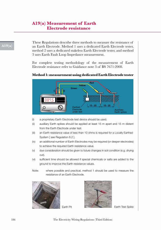
186 The Electricity Wiring Regulations (Third Edition)
A19(a)
A19(a) Measurement of Earth Electrode resistance
YellowRed
GreenE
P
EarthedElectrodeunder test
AuxilliaryEarth spikes
15 - 25 15 - 25
SAFETY EARTH CONNECTION
DO NOT REMOVE
Earth Test SpikeEarth Pit
Note: where possible and practical, method 1 should be used to measure the resistance of an Earth Electrode.
These Regulations describe three methods to measure the resistance of an Earth Electrode. Method 1 uses a dedicated Earth Electrode tester, method 2 uses a dedicated stakeless Earth Electrode tester, and method 3 uses Earth Fault Loop Impedance measurement.
For complete testing methodology of the measurement of Earth Electrode resistance refer to Guidance note 3 of BS 7671:2008.
Method 1: measurement using dedicated Earth Electrode tester
(i) a proprietary Earth Electrode test device should be used.
(ii) auxiliary Earth spikes should be applied at least 15 m apart and 15 m distant
from the Earth Electrode under test.
(iii) an Earth resistance value of less than 10 ohms is required for a Locally Earthed
System [ see Regulation 6.2 ].
(iv) an additional number of Earth Electrodes may be required (or deeper electrodes)
to achieve the required Earth resistance value.
(v) due consideration should be given to future changes in soil condition (e.g. drying
out).
(vi) sufficient time should be allowed if special chemicals or salts are added to the
ground to improve the Earth resistance values.

187The Electricity Wiring Regulations (Third Edition)
A19(a)
A19(a) Continued...
Method 2: measurement using dedicated stakeless Earth Electrode tester
Method 3: measurement using an Earth Fault Loop Impedance tester
Refer to Appendix A19(b) and A19(c).
Earth connections
Current clamp
Voltage clamp
Electrode under test
A19(a) Measurement of earth electrode resistance
(i) This method uses an Earth clamp-based tester without the need to disconnect
the Earthing Conductor.
(ii) This method is used when there are a number of Earth Electrodes and it is not
possible to use Method 1.
(iii) The larger the number of Earth Electrodes, the closer the measurement would
be to the electrode under test as the measurement is the Earth Electrode under
test in series with all other Earth paths in parallel.
(iv) It is important to highlight that for this method to be effective, there must be a
loop resistance to measure and the Earth mass must be part of the
measurement.

188 The Electricity Wiring Regulations (Third Edition)
A19(b)
A19(b) Measurement of Distribution Company supply impedance (Ze)
Main EarthedEquipotential Bonding
External Earth LoopImpedance Tester
Main EarthTerminal
Main Distribution Board
To Earth Electrode
A Earth BarTest Link removed
and Earth ElectrodeConnection removed
A
MCCB +
E/F
MCCB +
E/F
Notes:1. Caution: this test is carried out under live conditions but with the main isolator secured in the off position.2. Ze may be measured directly at the Supply Intake with a specialist Earth Loop Impedance tester. Such devices apply a resistance (typically 10 ohms) between a phase conductor and the earth conductor of the incoming supply. The test draws a current of around 20A but is only applied for a few cycles (e.g. 40ms). The device measures the drawn current and divides this into the measured supply voltage to give the loop impedance (the test resistance applied by the device is subtracted).3. As an alternative Ze may be calculated from measurement of the total earth fault loop impedance measured within the installation (see A19c) using the formula: ZS = Ze + ZR1+R2
Where:Zs = total Earth Fault Loop ImpedanceZe = Distribution Company supply impedanceZR1+R2 = impedance of the longest circuit in the Installation, taken by measuring a circuit phase conductor impedance R1, and the same circuit’s Earthing Conductor impedance R2.4. For further advice see reference book “ Advanced Testing Technique”.
Note 1: caution: this test is carried out under live conditions but with the main isolator secured in the off position.
Note 2: Ze may be measured directly at the Electricity Intake with a specialist Earth Loop Impedance tester. Such devices apply a resistance (typically 10 ohms) between a phase conductor and the earth conductor of the incoming supply. The test draws a current of around 20A but is only applied for a few cycles (e.g. 40ms). The device measures the drawn current and divides this into the measured supply voltage to give the loop impedance (the test resistance applied by the device is subtracted).
Note 3: as an alternative Ze may be calculated from measurement of the total Earth Fault Loop Impedance measured within the Electrical Installation (see A19(c)) using the formula:
Where:Zs = total Earth Fault Loop ImpedanceZe = Distribution Company supply impedanceZR1+R2 = impedance of the longest circuit in the Installation, taken by measuring a circuit phase
conductor impedance R1, and the same circuit’s Earthing Conductor impedance R2.
Note 4: For further advice see reference book “ Advanced Testing Technique”.
Note 5: Test should be repeated for the Earth Electrode.
Main EarthedEquipotential Bonding
External Earth LoopImpedance Tester
Main EarthTerminal
Main Distribution Board
To Earth Electrode
A Earth BarTest Link removed
and Earth ElectrodeConnection removed
A
MCCB +
E/F
MCCB +
E/F
Notes:1. Caution: this test is carried out under live conditions but with the main isolator secured in the off position.2. Ze may be measured directly at the Supply Intake with a specialist Earth Loop Impedance tester. Such devices apply a resistance (typically 10 ohms) between a phase conductor and the earth conductor of the incoming supply. The test draws a current of around 20A but is only applied for a few cycles (e.g. 40ms). The device measures the drawn current and divides this into the measured supply voltage to give the loop impedance (the test resistance applied by the device is subtracted).3. As an alternative Ze may be calculated from measurement of the total earth fault loop impedance measured within the installation (see A19c) using the formula: ZS = Ze + ZR1+R2
Where:Zs = total Earth Fault Loop ImpedanceZe = Distribution Company supply impedanceZR1+R2 = impedance of the longest circuit in the Installation, taken by measuring a circuit phase conductor impedance R1, and the same circuit’s Earthing Conductor impedance R2.4. For further advice see reference book “ Advanced Testing Technique”.

189The Electricity Wiring Regulations (Third Edition)
A19(c)
A19(c) Measurement of total Earth Fault Loop Impedance (Zs)
RYB
RYB
RYB
Final Distribution Board
Main Distribution Board
CECs remainconnected
Bonding Conductors
fromFDB
RCD RCD
to light(bulb removed from pendant)
to switch(must be ON)
to TestInstrumentEarth Electrode
Incoming Supply Cable
Note 1: caution: this test is carried out under live conditions with the circuits under test energised but no load is connected.
Note 2: a specialist instrument is used which measures the total Earth Loop Impedance Zs using a similar principle as described in A19(b). The instrument must not operate any RCD in circuit.
Note 3: the instrument may be directly connected to a socket-outlet (using the test plug provided) and should be used at the farthest point on a radial circuit or the mid point of a ring circuit. Alternatively, the instrument may be used at an Accessory connection point (e.g. lighting ceiling rose) with the appropriate test probes.
Note 4: for further advice see reference book “Testing Electrical Installations”.

190 The Electricity Wiring Regulations (Third Edition)
A19(d)
A19(d) Circuit continuity, (R1+R2) and (R1+Rn) tests
Radial Circuits and lighting Circuits:
1. This method tests the combined phase and Earth resistance (R1+R2) and phase and neutral resistance (R1+Rn) for each Circuit by applying short leads (not at the same time) at the Distribution Board, and measuring from the terminals of the farthest connection point or socket-outlet.
2. The polarity can be checked at each Accessory (i.e. only one of the live / neutral terminals should show continuity to Earth, and there should be no continuity between live and neutral).
3. If an Accessory has been wired incorrectly from another phase or neutral conductor, the test will not work (e.g. crossed Circuits or “borrowed neutral”).
4. For lighting Circuits the light switches should be ON to test the wire through the switch.
5. For metal conduit Circuits the CEC at the conduit/ back-box should be disconnected in order to accurately measure R1+R2.
Shorting LeadR1+Rn
RYB
RYB
RYB
Final DB A
RYB
RYB
RYB
Final DB A
Check polarity(neutral unearthed)
A19(d) Circuit continuity, (R1+R2) and (R1+Rn) tests
Check polarityand record R1+R2(and no continuityto neutral)
Shorting LeadR1+R2
Record R1+Rn(and no continuityto Earth / CEC)
R1+Rn
to switch(must be ON)
to lamp holder
“borrowed neutral”
>100MΩ

191The Electricity Wiring Regulations (Third Edition)
A19(d)
Shorting LeadR1+Rn
RYB
RYB
RYB
Final DB A
RYB
RYB
RYB
Final DB A
Check polarity(neutral unearthed)
A19(d) Circuit continuity, (R1+R2) and (R1+Rn) tests
Check polarityand record R1+R2(and no continuityto neutral)
Shorting LeadR1+R2
Record R1+Rn(and no continuityto Earth / CEC)
R1+Rn
to switch(must be ON)
to lamp holder
“borrowed neutral”
>100MΩ
A19(d) Continued...
Ring Circuits
1. For Ring Circuits, the test consists of two stages: (a) the measurement of end to end resistance of each
conductor. (b) the measurements of R1+R2, R1+Rn and checking there
areno‘bridges’inthering.

192 The Electricity Wiring Regulations (Third Edition)
Note 1: these tests are carried out on dead Circuits. The main isolator must be secured in the off position.
Note 2: for new Electrical Installations, these tests should be carried out when Accessories are in position but prior to energising the Electrical Installation.
Note 3: Circuit continuity tests must be measured for all Circuits and the resistance values recorded on the test report, see Appendix A20(d).
A19(d)
A19(d) Continued...
2. For part 1(a), measurement of the phase and neutral loops should give equal values. The Earth loop may be of slightly higher resistance if it is wired with a smaller conductor.
3. For part 1(b), measurement at any point on the ring between phase and neutral gives ½ the value measured in part 1(a).
4. To measure R1+Rn for a Ring Circuit, the two phase and neutral conductors from the ring are cross connected. The measurement at any point on the ring between phase and neutral should give ½ the value measured in part 1(a). If equal resistances are not observed around the ring then this indicates the presence of a bridge or wrong cross-connections at the FDB end of the Circuit.
5. To measure R1+R2 for a Ring Circuit the two phase and Earth conductors from the ring are cross connected. The readings at each point in the ring may vary slightly for a very long circuit (since the CEC is a smaller cross-section).
6. The highest value obtained represents the maximum R1+R2 value for the Circuit, and should be recorded on the test form.
A19(c) continuation
Ring circuits continuity:
FDB
N
L
FDB
NL
FDB
LE
A19(e)A19(d)
(R1 + R2)(R1 + Rn)Conductor end to end test

193The Electricity Wiring Regulations (Third Edition)
A19(d)A19(e)
A19(e) Lamp holder Circuit polarity tests
RYB
RYB
RYB
Final DB
Shorting cable applied at Final DB between phase conductor and Earth Conductor of Circuitunder test
To switch(must be ON)
To FinalDB
to lamp holder
Notes:
1. This test is carried out on dead circuits. The main isolator must be secured in the OFF position.2. The polarity test is required to confirm that all single pole devices, and lamp holders with an outer neutral contact (i.e. ES screw type) are correctly connected3. Single pole devices ( eg. light switches ) must only be connected in the live conductor.4. The test is carried out by measuring continuity between the earth terminal and live terminal at an accessory such as an ES pendant light fitting , after a shorting cable has been applied between the relevant phase conductor and earth bar at the Final Distribution Board.
to TestDevice
Earth Bar
OFF
A
A19(e) Lamp Holder circuit polarity tests
Note 1: this test is carried out on dead Circuits. The main isolator must be secured in the OFF position.
Note 2: the polarity test is required to confirm that all single pole devices, and lamp holders with an outer neutral contact (i.e. ES screw type) are correctly connected.
Note 3: single pole devices ( eg. light switches ) must only be connected in the live conductor.
Note 4: the test is carried out by measuring continuity between the Earth terminal and live terminal at an Accessory such as an ES pendant light fitting, after a shorting cable has been applied between the relevant phase conductor and Earth bar at the Final Distribution Board.
A19(e)

194 The Electricity Wiring Regulations (Third Edition)
A19(f)
A19(f) Segregation and insulation resistance tests
Circuit Nominal Voltage
Test Voltage (d.c.)
Minimum insulation resistance (M ohms)
SELV and PELV 250 0.25
up to 500 V 500 0.5
1. Insulation resistance should be checked between all live conductors, and between live conductors and Earth. For SELV and PELV systems, insulation resistance should be measured between the Extra-Low Voltage and higher Voltage conductors at a d.c. test Voltage of 500 V.
2. The test instrument should be capable of producing a d.c. test Voltage of 500 V when loaded to 1 mA and be capable of measurement of up to 200 M ohm.
3. The minimum acceptable value of insulation resistance for any test is 0.5 M ohm for LV systems and 0.25 M ohm for SELV and PELV systems.
4. The supply should be disconnected and all current-using equipment switched off (including neon indicator lamps, Luminaires, voltmeters, electronic devices such as dimmer switches, starters, RCDs with amplifiers etc). Alternatively, a limited test can be carried with the phase and neutral conductors connected together and testing to Earth.
5. The method of testing requires the connection of all three phases and neutral bar to Earth using temporary Earth wires.
6. The test measures the insulation resistance of each conductor wire with all other conductors connected to Earth. The test is done with all phase wires, all neutral wires and all Earth wires and the values recorded in installation testing report, refer to Appendix A20(d).
7. This test method checks the segregation of the conductor from all other wires. Care is to be taken when testing the insulation resistance of the Earth connections to ensure that there is no continuity between the equipment and containment systems.
8. Insulation measurements should be made at each Distribution Board.
A19(g)A19(f)

195The Electricity Wiring Regulations (Third Edition)
A19(f)
A19(f) Continued...
MainEarth
Terminal
R1
Y1
B1
R3
Y3
B3
R4
Y4
B4
R7
Y7
B7
R8
Y8
B8
Y2
B2
R2
R5
Y5
B5
Y6
B6
R6
R1N
R1E
Y1E
B1E
R2E
Y2E
Y1N
B1N
R5N
Y5N
B5N
R6N
500V
OFF
A19(f) Segregation and Insulation resistance testTest Voltage
(d.c.)
Minimum insulation resistance
(M ohms)
SELV and PELV 250 0.25
up to 500 V 500 0.5
Circuit Nominal Voltage
1. Insulation resistance should be checked between all live conductors, and between live conductors and Earth. For SELV and PELV systems insulation resistance should be measured between the extra-low voltage and higher voltage conductors at 500 V.2. The test instrument should be capable of producing a d.c. test voltage of 500 V when loaded to 1 mA and be capable of measurement of up to 200 M ohm.3. The minimum acceptable value of insulation resistance for any test is 0.5 M ohm for LV systems and 0.25 M ohm for SELV and PELV systems.4. The supply should be disconnected and all current-using equipment switched off (including neon indicator lamps, luminaires, voltmeters, electronic devices such as dimmer switches, starters, RCDs with amplifiers etc). Alternatively, a limited test can be carried with the phase and neutral conductors connected together and testing to earth. 5. The method of testing requires the connection of all three phases and neutral bar to earth using temporary earth wires. 6. The test measures the insulation resistance of each conductor wire with all other conductors connected to earth. The test is done with all phase wires, all neutral wires and all earth wires and the values recorded in installation testing report, refer to Appendix A20(d). 7. This test method checks the segregation of the conductor from all other wires. 8. Insulation measurements should be made at each Distribution Board.
Temporary earth wires
bridge
break
Illustration of insulation test procedure:
All wires connected to Earth, except wire to be tested. A bridge will be detected. A break in the conductor will not be detected (checked by continuity test).
>100MΩ
>100MΩ
A19(g) A19(f)

196 The Electricity Wiring Regulations (Third Edition)
A19(g) Sequence of testing for new Electrical Installations
Correct sequence for safe testing
Before supply is connected:
1. Continuity of Earth Conductors (Main Earth Conductors and
Circuit Earth Conductors)
2. Continuity of main and supplementary bonding conductors
3. Continuity of Ring Circuit conductors
4. Polarity tests of all Circuits
5. Segregation and insulation resistance measurements of all conductors
6. Earth Electrode resistance
After supply is connected:
1. Distribution Company Earth Fault Loop Impedance measurement
2. Re-confirm polarity
3. Total Earth Fault Loop Impedance measurements
4. Prospective fault current measurements
5. Operation of RCD and Earth fault devices
6. Operation of switches and isolators
Note 1: safety precautions must be observed during testing, including locking off isolators and switches, safeguarding against contact with test voltages, replacement of test links and removal of tools after completion. The order of test sequence must be observed, in particular testing of Earth Conductors (dangerous test voltages can appear on the installation metalwork if Earth Conductors are inadvertently disconnected or broken).
Note 2: testing of RCDs must include measurement of the operating time (ms) at In and at 5 x In, as well as check of non-operation at 50% x In at both 0º and 180º.
A19(g)

197The Electricity Wiring Regulations (Third Edition)
Project / Building Name:................................................................................
Address / Location: ..............................................................................................
Certificate No. / Ref:
………………….......
Details of Client / Customer: ……………………………………………………………………………...................
Electricity account no. / contact details: ……………………………………………………………………………...
New or modified installation: New: Modification: Existing:
Brief description of work carried out: ……………………………………………………………………………………
………………………………………………………………………. Previous Certificate number:.........................
Supply Characteristics:Earthing System: (TT, TN-S, TN-S and TT);
Incoming Cable Size & Type:
.........…………
.........…………
Earth Electrode(s )Resistance:
Earth Electrode(s) Location:
............………
............………
Main CB type & rating: .........………… Main Earth Conductor Size: ............………
Protective System (ELPS, EEBS); .........………… Earth Fault Loop Impedance: ............………
Max Prospective Fault Current: .........………… Total Connected Load: ............………
Meter ref. no’s and type: ..............................................................................................…………
Total Diversified Load: ...................... Total Floor area: ......................
Special Circuits:
Details of Designer: ……………………………………………………………………………...................................
Contact Details: ……………………………………………………………………………...................................
We hereby declare that the work completed by us in relation to the above named electrical installation, and detailed in the reference drawings and documents listed below, has been carried out with due skill and care, and in accordance with the Electricity Wiring Regulations published by the Regulation & Supervision Bureau for the Water, Wastewater and Electricity Sector in Abu Dhabi:
Authorised signatory & name: ……………………………..….....…… Date: …………………….....................
………………………..……….....……
Reference drawings and schedules: ……………………...…….. Company Stamp: …………................
Registered Engineer Certificate No. .................................................. Certificate Expiry Date: .....................................................................
Details of Installer: ...............…………………………… Licence Number: ………………….....................
Contact Details: ……………………………………………………………………..…………………..................
We hereby declare that the work completed by us in relation to the above named electrical installation, and detailed in the reference drawings and documents listed below, has been carried out with due skill and care, and in accordance with the Electricity Wiring Regulations published by the Regulation & Supervision Bureau for the Water, Wastewater and Electricity Sector in Abu Dhabi:
Authorised signature & name: ………………………………………… Date: ……………….…............................
………………………………………………………………………….....
Reference drawings and schedules: .....………………………..……… Company Stamp: ……………..................
Registered Engineer Certificate No. ............................................. Certificate Expiry Date: ........................................................................
A20(a) Electrical Installation Certificate
A20(a)
Details (e.g. special circuits without RCD protection, functional earthing arrangements): …………………
………………………………………………....……………………………………………………………………………...
................................……………………………………..............................................................................................

198 The Electricity Wiring Regulations (Third Edition)
A20(b)
Project / Building Name:................................................................................
Address / Location: ..............................................................................................
Report No
Details of Client / Customer: ……………………………………………………………………………...................
Electricity account no. / contact details: ……………………………………………………………………………...
New or modified installation: New: Modification: Existing:
Reason for Inspection (first inspection, routine inspection, other): ...................................................................
............................................................................................... Installation Certificate number: …………..
Supply Characteristics:
Earthing System: (TT, TN-S, TN-S and TT); .........……… Earth Electrode(s) Resistance: ............………..
Incoming Cable Size & Type: .........……… Earth Electrode(s) Location: ............………..
Main CB type & rating: .........……… Main Earth Conductor Size: ............………..
Protective System (ELPS, EEBS): .........……… Earth Fault Loop Impedance: ............………..
Max Prospective Fault Current: .........……… Total Connected Load: ............………..
Meter ref. no’s and type: .............................................................................................................................
Total Diversified Load: .............................................................................................................................
General Details of Inspection & Testing:
Date of last inspection & test: .......................................................................................................
Any modifications noted: No Yes Details: ........................................................................
Estimated age of installation & estimated age of modifications: ............................................................... Date of next planned inspection: .......................................................................................................
Any dangerous conditions or urgent work required (give details over leaf): No Yes
Any work or improvements recommended (give details over leaf): No Yes
Extent of inspection: All: Part: Areas not tested / inspected:...........................................................
Inspection carried out by: .…………………………………………………………………………................
Contact Details: …………………………………………………………………………….............
We hereby declare that the inspection and testing completed by us in relation to the above named installation, and detailed over leaf, has been carried out with due skill and care, and in accordance with the Electricity Wiring Regulations published by the Regulation & Supervision Bureau for the Water, Wastewater and Electricity Sector in Abu Dhabi:
Authorised signature & name: ……………………………..…..…… Date:……………………....................
Company Stamp: ..................................... Registered Engineer Certificate No: …....….........................….
Certificate Expiry Date: .............................................. Company Stamp: ..................................................
A20(b) Inspection report (front)
A20(c)A20(b)

199The Electricity Wiring Regulations (Third Edition)
A20(b)A20(c)
Equipment Inspected: satisfactory not satisfactory (give details /comments)
not applicable urgent work required
Main intake room condition: .......................................................................................
Metering Equipment: .......................................................................................
Main Distribution Board: .......................................................................................
Main Isolation Device (CB): .......................................................................................
Main LV switchboard (if any): .......................................................................................
Incoming supply cable(s): .......................................................................................
Main earth conductor, earth pits,
and MET;.......................................................................................
Sub Distribution Boards (give ref. no’s): .......................................................................................
.......................................................................................
.......................................................................................
Distribution Cables (between DBs): .......................................................................................
.......................................................................................
Main Earth Leakage Protective
Device(s):.......................................................................................
Circuit cables (where visible): .......................................................................................
Power factor correction equipment: .......................................................................................
Standby generation equipment: .......................................................................................
Power points & socket outlets: .......................................................................................
.......................................................................................
Internal Inspection of sample points (10% sample):
List circuits/connections inspected .......................................................................................
.......................................................................................
.......................................................................................
A20(c) Inspection report (back)
A20(c)

200 The Electricity Wiring Regulations (Third Edition)
A20(d)
A20
(d)
Ele
ctri
cal I
nst
alla
tion
tes
tin
g re
por
t
Proj
ect /
Bui
ldin
g N
ame:
......
......
......
......
.....
Addr
ess
/ Loc
atio
n:...
......
......
......
......
......
....
Dist
ribut
ion
Boar
d N
o. /
Ref:.
......
......
......
....
Fed
from
:.....
......
......
......
......
......
......
......
......
Docu
men
t No.
/ Re
f:....
......
......
......
......
......
......
......
......
......
.
Test
ed b
y:...
......
......
......
......
......
......
......
......
......
......
......
......
......
......
......
......
......
......
......
......
......
......
......
......
......
......
......
..
Date
:.....
......
......
......
......
......
......
......
......
......
......
......
......
......
RCD
test
er:..
......
......
......
......
......
......
......
......
..( s
eria
l no.
)
Loop
impe
danc
e te
ster
:.....
......
......
......
......
...( s
eria
l no.
)
Con
tinui
ty te
ster
:.....
......
......
......
......
......
......
..( s
eria
l no.
)
Insu
latio
n te
ster
:.....
......
......
......
......
......
......
...( s
eria
l no.
)
Incomer
Bus
bar
sect
ion
/ R
CD
CC
Tre
f.N
o.
MC
Bra
ting
(A)
Pha
se&
Neu
tral
size
mm
2
Ear
thsi
ze
mm
2C
ircui
tD
escr
iptio
n
Con
tinui
ty T
est (
ohm
s)In
sula
tion
Res
ista
nce
(M o
hms)
Polarity(see note 2)
Total Earth LoopImpendance (zs)
Short Circuit current PSCC (kA)
RC
DTe
stR
emar
ks /
Faul
ts(S
ELV
circ
uits
, et
c)
R1 + R2(Ohms)
R1 + Rn (Ohms)
Rin
gL see
note
1
N see
note
1
E see
note
1
1 x
In (m
s)5
x In
(ms)
1/2
x In
(trip
/no
trip
)
R1 (Line)
Rn (Neutral)
R2 (Earth)
R1
Y1
B1
R2
Y2
B2
R3
Y3
B3
R4
Y4
B4
Not
e 1:
in
sula
tion
resi
stan
ce m
easu
red
for
each
con
duct
or w
ith a
ll ot
her
phas
e, n
eutr
al a
nd E
arth
Con
duct
ors
conn
ecte
d to
Ear
th.
Not
e 2:
fo
r po
larit
y te
st, c
heck
all
3 co
mbi
natio
ns o
n N
-E, N
-Ph,
Ph-
E, a
nd re
cord
num
ber
of p
oint
s/ac
cess
orie
s ch
ecke
d.
Not
e 3:
m
ain
and
supp
lem
enta
ry b
ondi
ng c
ondu
ctor
s to
be
test
ed fo
r co
ntin
uity
and
res
ults
to b
e re
cord
ed.
A20(e)
A20
(e)
Loa
d d
istr
ibu
tion
sch
edu
les
A20(d)

201The Electricity Wiring Regulations (Third Edition)
A20(d)A20(e)
A20
(e)
Loa
d d
istr
ibu
tion
sch
edu
les
Proj
ect/B
uild
ing:
.....
......
......
......
......
......
......
......
......
. Ad
dres
s/Lo
catio
n: ..
......
......
......
......
......
......
......
......
.Di
strib
utio
n Bo
ard
No.
/Ref
: ....
......
......
......
......
......
...Fe
d fro
m: .
......
......
......
......
......
......
......
......
......
......
....
Mai
n C
ontra
ctor
: ....
......
......
......
......
......
......
......
......
......
......
......
......
......
....
Elec
trica
l Con
tract
or: .
......
......
......
......
......
......
......
......
......
......
......
......
......
In
com
ing
Cab
le s
ize /
type
: ....
......
......
......
......
......
......
......
......
......
......
.....
Mai
n br
eake
r typ
e &
ratin
g: ..
......
......
......
......
......
......
......
......
......
......
......
.
Fina
l Dis
tribu
tion
Boar
dDa
te: .
......
......
......
......
......
......
......
......
......
......
......
Docu
men
t No.
.....
......
......
......
......
......
......
......
.....
Bus
bar
sect
ion/
R
CD
CC
Tre
f.N
o.
MC
Bra
ting
(A)
Cab
le S
ize
Cab
le
ratin
gA
(kW
)[s
ee
note
s]
Circ
uit n
ame
/ P
oint
refe
renc
e
No.
of p
oint
s(d
oubl
e /
sing
le)
Cable Type
Circuit Type
Con
nect
ed
Load
per
po
int (
kW)
Circ
uit L
oad
in (k
W)
Div
ersi
ty
Type
Div
ersi
ty
Fact
orR
emar
ksP
hase
&
Neu
tral
Siz
em
m2
Ear
thsi
zem
m2
Number
Type
Number
Type
Number
Type
RY
B
..........................................................................
Section 1 ........................
R1
Y
1B
1R
2Y
2B
2R
3Y
3B
3
Section 2 .........................
R4
Y4
B4
R5
Y5
B5
R6
Y6
B6
Gro
ss A
rea
= ..
......
......
......
......
......
......
......
......
......
. sq
mD
ivers
ified
Load
Typ
esPW
RLT
GW
HM
OAO
Tota
l Con
nect
ed L
oads
(kW
)TC
L=...
......
....k
W
Floo
r Are
a D
ivers
ified
Load
= ..
......
......
......
......
......
......
W/s
q m
DB
Loa
dW
/sq
mLo
ad A
fter D
ivers
ity (k
W)
TDL=
......
......
.kW
Not
e 1:
ca
ble
ratin
gs ta
ken
at ..
.... º
C a
nd ..
... p
ower
fact
or, i
nsta
lled
as s
ingl
e C
ircui
ts in
con
duit.
Not
e 2:
ca
ble
ratin
g m
ust b
e ab
ove
Circ
uit C
onne
cted
Loa
d an
d at
leas
t 1.1
5 tim
es M
CB
nom
inal
rat
ing.
Not
e 3:
w
here
RC
BO
s ar
e us
ed, t
he b
usba
r se
ctio
n in
the
abov
e is
repl
aced
with
the
mA
rat
ing.
Not
e 4:
D
iver
sifie
d Lo
ad ty
pes
can
be c
ateg
oris
ed a
s po
wer
, lig
htin
g, w
ater
hea
ting,
mot
or lo
ads,
a/c
etc
.
Not
e 5:
C
ircui
t typ
es c
an b
e ca
tego
rised
as
radi
al, r
ing,
ligh
ting.
A20(e)

202 The Electricity Wiring Regulations (Third Edition)
A20(e)
A20
(e)
Con
tin
ued
...
Proj
ect /
Bui
ldin
g N
ame:
......
......
......
......
......
......
......
......
......
...
Addr
ess
/ Loc
atio
n:...
......
......
......
......
......
......
......
......
......
......
..
Dist
ribut
ion
Boar
d N
o. /
Ref:.
......
......
......
......
......
......
......
......
..
Fed
From
:.....
......
......
......
......
......
......
......
......
......
......
......
......
...
Mai
n C
ontra
ctor
:.....
......
......
......
......
......
......
......
......
......
......
.....
Elec
trica
l Con
tract
or:..
......
......
......
......
......
......
......
......
......
......
..
Inco
min
g C
able
size
/ Ty
pe:..
......
......
......
......
......
......
......
......
...
Mai
n Br
eake
r Typ
e &
Ratin
g:...
......
......
......
......
......
......
......
......
.
Sub
Mai
n Di
strib
utio
n Bo
ard
Date
: ....
......
......
......
......
......
......
......
......
......
..
Docu
men
t No.
.....
......
......
......
......
......
......
....
Sing
le /
Thre
ePh
ase
Rat
ing
(Am
ps)
Cab
leTy
pe
Cab
le T
ype
/ Size
Con
nect
ed L
oad
Tota
l
Diversity Type
Diversity Factor
Div
ersi
fied
Load
Tota
l
Rem
arks
RC
Dm
AM
CC
BN
o. o
fC
able
sN
o. o
fC
ores
Size
mm
2
Earth
mm
2
R-P
h(k
W)
Y-Ph
(kW
)B
-Ph
(kW
)(k
W)
R-P
h(k
W)
Y-Ph
(kW
)B
-Ph
(kW
)(k
W)
Out
goin
g W
ays
1 2 3 4 5 6 7 8
Tota
l Con
nect
edP
hase
Loa
dsTo
tal D
iver
sifie
d P
hase
Loa
ds
Gro
ss A
rea:
......
......
......
......
......
......
......
......
.....s
q m
Div
ersi
fied
Load
Typ
esPW
RLT
GW
HM
OA
CTo
tal C
onne
cted
Loa
dkW
Floo
r A
rea
Div
ersi
fied
Load
:.....
......
......
......
..W/s
q m
SM
DB
Loa
dLo
ad a
fter
Div
ersi
tykW
W/s
q m
Ove
rall
Div
ersi
ty%
Not
e:
SM
DB
out
goin
g w
ays
mus
t be
size
d in
acc
orda
nce
with
the
Con
nect
ed L
oad
and
SM
DB
inco
mer
will
typi
cally
be
size
d in
acc
orda
nce
with
the
dive
rsifi
ed lo
ad.
A20(e)
A20
(e)
Con
tin
ued
...
A20(e)

203The Electricity Wiring Regulations (Third Edition)
A20(e)A20(e)
A20
(e)
Con
tin
ued
...
Not
e:
MD
B o
utgo
ing
way
s an
d in
com
er w
ill ty
pica
lly b
e si
zed
in a
ccor
danc
e w
ith th
e di
vers
ified
load
.
Proj
ect /
Bui
ldin
g N
ame:
......
......
......
......
......
......
......
......
......
...
Addr
ess
/ Loc
atio
n:...
......
......
......
......
......
......
......
......
......
......
..
Dist
ribut
ion
Boar
d N
o. /
Ref:.
......
......
......
......
......
......
......
......
..
Fed
From
:.....
......
......
......
......
......
......
......
......
......
......
......
......
...
Mai
n C
ontra
ctor
:.....
......
......
......
......
......
......
......
......
......
......
.....
Elec
trica
l Con
tract
or:..
......
......
......
......
......
......
......
......
......
......
..
Inco
min
g C
able
size
/ Ty
pe:..
......
......
......
......
......
......
......
......
...
Mai
n Br
eake
r Typ
e &
Ratin
g:...
......
......
......
......
......
......
......
......
.
Mai
n Di
strib
utio
n Bo
ard
Date
: ....
......
......
......
......
......
......
......
......
......
..
Docu
men
t No.
.....
......
......
......
......
......
......
....
Sing
le /
Thre
ePh
ase
Rat
ing
(Am
ps)
Cab
leTy
pe
Cab
le T
ype
/ Size
Con
nect
ed L
oad
Tota
l
Diversity Type
Diversity Factor
Div
ersi
fied
Load
Tota
l
Rem
arks
RC
Dm
AM
CC
BN
o. o
fC
able
sN
o. o
fC
ores
Size
mm
2
Earth
mm
2
R-P
h(k
W)
Y-Ph
(kW
)B
-Ph
(kW
)(k
W)
R-P
h(k
W)
Y-Ph
(kW
)B
-Ph
(kW
)(k
W)
Out
goin
g W
ays
1 2 3 4 5 6 7 8
Tota
l Con
nect
edP
hase
Loa
dsTo
tal D
iver
sifie
d P
hase
Loa
ds
Gro
ss A
rea:
......
......
......
......
......
......
......
......
.....s
q m
Div
ersi
fied
Load
Typ
esPW
RLT
GW
HM
OA
CTo
tal C
onne
cted
Loa
dkW
Floo
r A
rea
Div
ersi
fied
Load
:.....
......
......
......
..W/s
q m
SM
DB
Loa
dLo
ad a
fter
Div
ersi
tykW
W/s
q m
Ove
rall
Div
ersi
ty%
A20(e)

204 The Electricity Wiring Regulations (Third Edition)
A20(f)
A20
(f)
Sola
r P
V t
est
rep
ort
Solar PV Test Report Initial Verification
Periodic Verification
Electrical Installation address Reference
Date
Description of work under test Inspector
Test InstrumentsString 1 2 3 4 n
Array Module Quantity
Array parameters (as specified)
Voc (stc)Isc (stc)
String over-current protective device
Type Rating (A)DC Rating (V)Capacity (kA)
Wiring Type Phase (mm²) Earth (mm²)
String test Voc (V)Isc (A) Irradiance
Polarity check
Array insulation resistance
Test Voltage (V) Pos Earth (MΩ)Neg Earth (MΩ)
Earth Continuity (where fitted)Switchgear functioning correctly Inverter make / model Inverter serial number Inverter functions correctly Loss of mains test
Details of Designer: ……………………………………………………………………………...................Contact Details: ……………………………………………………………………………...................We hereby declare that the work completed by us in relation to the above named electrical installation, and detailed in the reference drawings and documents listed below, has been carried out with due skill and care, and in accordance with the Electricity Wiring Regulations published by the Regulation & Supervision Bureau for the Water, Wastewater and Electricity Sector in Abu Dhabi:Authorised signatory & name: ……………………………..….....…… Date: ………………............. ………………………..……….....……Reference drawings and schedules: ……………………...……....... Company Stamp: ............Registered Engineer Certificate No. .................................................. Certificate Expiry Date: .....................................................................
Details of Installer: ...............…………………………...................... Licence Number: .................Contact Details: ……………………………………………………………………..…………………..We hereby declare that the work completed by us in relation to the above named electrical installation, and detailed in the reference drawings and documents listed below, has been carried out with due skill and care, and in accordance with the Electricity Wiring Regulations published by the Regulation & Supervision Bureau for the Water, Wastewater and Electricity Sector in Abu Dhabi:Authorised signature & name: ………………………………………… Date: ………….…................…………………………………………………………………………....Reference drawings and schedules: .....………………………..……. Company Stamp: ...................Registered Engineer Certificate No. ............................................. Certificate Expiry Date: ........................................................................
A20(g)
A20
(g)
Sola
r P
V s
yste
m in
spec
tion
rep
ort
A20(f)

205The Electricity Wiring Regulations (Third Edition)
A20(f)
Solar PV Inspection Report Initial Verification
Periodic Verification
Installation address Reference
Date
Circuits inspected Inspector
Equipment/Circuits Inspected satisfactory not satisfactory (give details /comments)not applicable urgent work required
Generala.c part of the Electrical Installation is tested in accordance with Regulations 8.1
PV Distribution Boards room condition
PV Distribution Boards condition
Proper ventilation behind PV Array
Cable entry weatherproof Array frame suitably supported and secured; roof fixings weatherproof
PV Array design and installationAll d.c. components are rated for continuous operation at d.c. and at the maximum possible d.c. system voltage and maximum possible d.c. current
Protection by use of class II insulation adopted on the d.c. side
PV String cables and PV d.c. main cables are black in colour and Double Insulated
Wiring systems have been selected and erected to withstand the expected external influences such as wind, temperature and solar radiation
String cables are sized to accommodate the maximum fault current
Wiring systems are adequately supported and protected
If applicable, String over-current Protective Devices are fitted and correctly specified
Verify that a d.c. switch disconnector is provided on the d.c. side of the Inverter
If applicable, where blocking diodes are fitted, the reverse voltage rating is at least 2 × Voc stc of the PV String in which they are fitted
A20(g)
A20
(g)
Sola
r P
V s
yste
m in
spec
tion
rep
ort
A20(g)

206 The Electricity Wiring Regulations (Third Edition)
A20(g)
A20
(g)
Con
tin
ued
...
Equipment/Circuits Inspected satisfactory not satisfactory (give details /comments)not applicable urgent work required
Protection against overvoltage / electric shockTo minimise voltages induced by lightning, verify that the area of all wiring loops has been kept as small as possible
Module frame protective Earthing Conductors have been correctly installed and are connected to Earth
If applicable, check that a type B RCD is installed
Means of isolating the Inverter have been provided on the a.c. side
PV Array design and installationAll Circuits, Protective Devices, switches and terminals are suitably labelled
All d.c. junction boxes (PV generator and PV Array boxes) carry a warning label indicating that active parts inside the boxes are fed from a PV Array and may still be live after isolation from the PV Inverter and public grid supply
The main a.c. and d.c. isolating switches are clearly labelled
Dual supply warning labels are fitted at point of interconnection
A single line wiring diagram is displayed on site
Emergency shutdown procedures are displayed on site
All signs and labels are suitably affixed and durable
A21A20(g)

207The Electricity Wiring Regulations (Third Edition)
A20(g)A21
A21. General Marinas connection arrangements
Note 1: protection can be provided by a combination of suitably rated MCBs and suitably rated RCDs.
Note 2: Earth Leakage Protection shall be effective for leakage currents of no greater than 30 mA, refer to clause 9.9.16.
Connection to mains supply (single phase and three phase)
DB
RCBO (30mA)RCBO (10mA)
RCBO (10mA)
RCBO (10mA)
RCBO (10mA)
RCBO (10mA)
2 pole switch
Marina Pedestal
Single phase industrial socket-outlet
Single phase industrial socket-outlet
Single phase industrial socket-outlet
Single phase industrial socket-outlet
Single phase light
DB
RCBO (30mA)RCBO (10mA)
RCBO (10mA)
RCBO (10mA)
RCBO (10mA)
RCBO (10mA)
4 pole switch
Marina Pedestal
Single phase industrial socket-outlet
Single phase industrial socket-outlet
Three phase industrial socket-outlet
Three phase industrial socket-outlet
Single phase light
A21
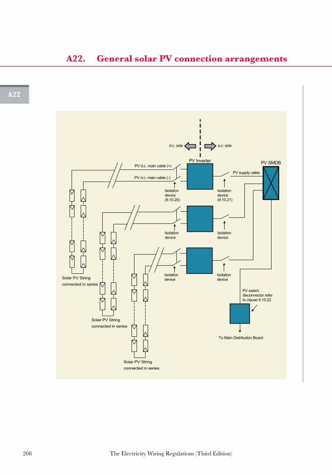
208 The Electricity Wiring Regulations (Third Edition)
A22
A22. General solar PV connection arrangements A22. General solar PV connection arrangements
a.c. sided.c. side
PV switch disconnector refer to clause 9.10.22
To Main Distribution Board
PV SMDB
PV supply cable
PV d.c. main cable (+)
PV d.c. main cable (-)
Solar PV Stringconnected in series
PV Inverter
a.c.
d.c.
Isolation device(9.10.20)
Isolation device(9.10.21)
Solar PV Stringconnected in series
a.c.
d.c.
Isolationdevice
Isolationdevice
Solar PV Stringconnected in series
a.c.
d.c.
Isolationdevice
Isolationdevice
A22

Guidance notes


211The Electricity Wiring Regulations (Third Edition)
GGuidance notes
G1. Guidance note on supply Voltage change 213
G2. Estimation of Connected Load and diversity factors 214
G3. Photographs
(a) Photograph of busbar riser 225
(b) Photograph of Final Distribution Board (horizontal DIN rail) 226
(c) Photograph of Final Distribution Board (vertical, split busbar type) 227
G4. Electric shock, ELP and EEB systems
(a) Direct Contact with electricity 228
(b) Indirect Contact with electricity 229
(c) Main and Supplementary Earthed Equipotential Bonding (EEB) 230
(d) Illustration of Earth Leakage Protected System (ELPS) 231
(e) Grading of RCDs in an ELP system 232
(f) ELP system supplied from LV switchroom 233
(g) Calculation of Touch Voltage (ELP system) 234
(h) Calculation of Touch Voltage (EEB system) 235
G5. Electric shock and RCD characteristics
(a) RCD operating characteristics and electric shock 236
(b) Typical values of body resistance and physiological effects 237
(c) RCD operating principle 238
(d) Types of RCDs 239
(e) Sources of tripping of RCDs 240

212 The Electricity Wiring Regulations (Third Edition)
G6. Protection of buried cables 241
G7. Common errors
(a) Exposed unsheathed cables at termination points 242
(b) Protection of high temperature connections 243
(c) Weather protected outdoor socket-outlets 244
(d) Earth tails in Accessories and connection boxes 245
(e) Minimum depth of buried plastic conduit 246
(f) CircuitidentificationnumbersonAccessoriesand Earth Conductors 247
(g) Missing grommets and sharp edges on Cable Tray 248
(h) Cables in ceiling-voids 249
(i) Cable glands for Earthing of armoured cable 250
(j) Earth continuity connections across Cable Tray and conduit 251
(k) Prohibited terminal blocks and taped connections 252
(l) Slotting of steel gland plates for single core cables 253
(m) Flex-outlets 254
G8. Typical lighting Circuit installations 255
G9. Isolation and switching 258
G10. Typical lightning protection system details
(a) Typical lightning protection system details 259
(b) Lightning Earth Electrodes 261
G11. Changes in the Third Edition (March 2014) 262

213The Electricity Wiring Regulations (Third Edition)
G1
G1. Guidance note on supply Voltage change
Distribution Companies in the UAE have traditionally based the design of their networks on the UK power system. Previously, the Voltage of supply was declared to be 240 V single-phase or 415 V three phase, with an allowed variation in Voltage of +/- 6%. With the harmonization of supply Voltages in Europe (in line with BS EN 50160) the supply Voltage is 230 / 400 V +/- 10%. In the UK, the variation is currently limited to +10% -6%.
These Regulations have adopted the same nominal Voltage of supply with a variation of +10% - 6% (clause 4.1.3). This range has been adopted to allow existing distribution network assets to continue to operatewithoutmodification,andalsoprovidesasuperiorVoltagerangeto Customers. With an allowed Voltage drop of 4% within an Owner’s Electrical Installation (clause 7.5.10) this ensures the total Voltage drop to Appliances will not exceed 10% of the nominal Voltage of 230/400 V.
225.6 240 254.4
207.0 230 253.0
216.2 230
-6% +10%
260250240230220210200
-10% +10%
-6% +6%
253.0
Old UK supply Voltage rangepreviously used in Abu Dhabi
BS EN 50160 supply Voltage
Range of supply Voltage adopted inthese Regulations

214 The Electricity Wiring Regulations (Third Edition)
G2
G2. Estimation of Connected Load and diversity factors
Load diversity
Where a Circuit consists of multiple points of utilisation (e.g. socket-outlets), the Circuit load current can be assessed by simply adding the individual full load current of all points of utilisation. While, this would provide a conservative design, it will lead to over sizing the Circuit because in reality the sum of individual loads rarely equal to the actual load current required by the Circuit. This is known as load diversity.
For example, the load seen at the Sub Main Distribution Board that is feeding multiple apartments in a residential building will rarely see all apartments at full load at the same time. Therefore, allowances for diversity between loads must be taken into consideration in sizing Final Circuits and other distribution Circuits. Moreover, certain Appliances such as a washing machine have a number of components that may be independently controlled and vary over time. Therefore, over the duration of the wash cycle, the total demand will not always be maintained at the full load rating, as various components switch in and out.
The allowances for diversity in an Electrical Installation varies depending on many factors, these factors may include:
(a) type and nature of the Electrical Installation (residential, commercial, industrial, etc);
(b) intended use of utilisation points (e.g. general use socket-outlets for the connection of portable Appliances compared to dedicatedsocket-outletsforafixedconnection);
(c) number of utilisation points in a Circuit (e.g. a SMBD feed two FDBs compared to 10 FDBs); and
(d) operating characteristics of the Connected Load (e.g. the use of a/c units in Abu Dhabi is essential in the summer and in many cases it will be running most of the time).
It is important to note that allowances for diversity in an Electrical Installation may vary between similar installation. Therefore, the designer of the Electrical Installation may select different allowances representing the intensity of usage (e.g. higher value for high usage Circuits, such as communal kitchens, lower value for lower occupancy dwellings, etc).

215The Electricity Wiring Regulations (Third Edition)
G2
G2. Continued...
ThisGuidancenoteprovidesdiversityallowancesforspecificsituations.The factors used may be increased or decreased by the designer depending on the intended design of the Electrical Installation. The designer must provide the relevant justification to the DistributionCompany.
Sizing of Final Circuits
As indicated in Clause 5.2.5 and Appendix A6(f), the relationship between the Circuit load current (Ic), the Protective Device nominal current rating (In), and the current carrying capacity of the Circuit conductors (Id) is as follows:
Ic≤In≤Idinaddition; Id≥1.15xIn(cablesmustselectedwithratingsatleast1.15timestheProtective Device nominal current rating).
For example, the Circuit full load current of a single phase 4 kWAppliance, can be calculated using the following formula (power factor = 1 for resistive load):
Current (Ic) = Power (W)
Voltage V x PF
Current (Ic) =
4000 = 17.4 A
230 x 1
Therefore, the Protective Device nominal current rating (In) must not be less than 20A (nearest standard rating), and the current carrying capacity for the Circuit conductor (Id) must be not less than 23A(20A x 1.15), assuming grouping and temperature rating factors to be 1. The above calculation ensures that the Circuit is suitably rated for the Appliance to draw 17.4A for a continuous period of time.
The relevant Protective Device nominal ratings, cable size and cable rating for typical Circuit applications are provided in Appendix A6(f). For other non-typical Circuit applications, the designer shall determine the appropriate Circuit rating based on the total Connected Load of all Appliances and knowledge of the intended Circuit application.

216 The Electricity Wiring Regulations (Third Edition)
G2
G2. Continued...
G2Final Circuit estimated Connected Load for sizing Final Distribution Board
For sizing the Final Distribution Board, the Connected Load of a Final Circuit is estimated by adding the load of all points of utilisation (e.g. socket-outlets) and items of Appliance connected to the Circuit and where appropriate making allowances for diversity. The table below gives the estimated Connected Load for typical Appliances that can beusedforsizingFinalDistributionBoards.Specificsiteinformationshould be used where available.
The table below should be used as a guide for sizing the Final Distribution Board only.
Connected Appliance per Final
Circuit Assumed Connected Load
Lighting
• sumofwattageofallLuminairesorassume100Wforeachlightingpoint(note1)
• chandelierlightingpoint–500W• lamp wattage plus losses of associated control
gearsuchasballastsandcapacitorsforfluorescentlighting(note2)
13Asocket-outlets–(forgeneralusefortheconnectionofportableAppliances)
• 200Weach(note3)
13Asocket-outlets/flexoutletsandindustrialsocket-outlets–(fixedAppliances)
• actualratingofAppliance
Waterheater • 1,500WoractualratingofAppliance
Washingmachine,dryer,dishwasher
• 1,500WeachoractualratingofAppliance
Cooker • 3,000Wplusthelargestringoractualrating
Fridge • 300WorfullratingofAppliance
Motors(e.g.lifts) • actualrating
Air Conditioning • splitair-conditioningunits–fullrating• windowair-conditioningunits–fullrating• centrala/cunits–fullrating

217The Electricity Wiring Regulations (Third Edition)
G2
G2. Continued...
G2Note1: where theConnectedLoadofaLuminaire is less than100W, then the
designofthelampholderassociatedwiththatLuminairemustonlypermittheinsertionofthistypeoflamp.TheConnectedLoadinthiscaseshouldbethehighestactuallampwattagethatcanbeaccommodatedbysuchlampholderorthatthecontrolgearcandeliver.
Note2: wherenoexactinformationisavailable,thelampwattagemustbemultipliedbynotlessthan1.8.
Note3: if the Connected Load on socket-outlet Circuits are known then thedesigner may choose to use specific values. For example, in an officebuildingwherethesocket-outletCircuitscompriseofbusinessmachineseachratedat150W,thenthedemandofeachsocket-outletpointwillbecountedas150W.
Note4: standbyloadsshouldnotbeconsideredwhensizingtheFinalDistributionBoard.Forexample,wherethreepumpsareconfiguredwithtworunandonestandby,thestandbypumploadshouldnotbe included insizingoftheFinalDistributionBoard.Insuchcasesprovisionforinterlocksmustbeprovidedtopreventoperationofallpumpssimultaneously.
Diversity allowance between Final Circuits for sizing Sub Main Distribution Board
The diversity allowances shown in the table below are for specificsituations andmeant to only provide guidance.The figures given inthe table may need to be increased or decreased depending on the particular circumstances. The table below is used as a guide for sizing of the Sub Main Distribution Boards only.
The table below can be used as a guide for sizing the Sub Main Distribution Boards feeding multiple Final Circuits downstream. For e.g., if a SMDB in a villa feeds one central water heater, then no diversity allowance is allowed. However, if a SMDB in a high rise buildingfeedsanumberof flatseachwithmultiplewaterheatersthen,50% diversity allowance can be used.

218 The Electricity Wiring Regulations (Third Edition)
G2
G2. Continued...
G2 Totalsumofthe estimated Connected Loads on all Final Circuits
Residential premises,villas,
flats
Shops,stores,offices,schools,
mosques,business premises
Hotels,motels,accommodation
houses
Lighting 75% 90% 90%
13Asocket-outlets–(forgeneraluseforthe connection ofportableAppliances)
50% 70% 50%
13Asocket-outlets/flexoutlets–(fixedAppliances)
50% 50% 50%
Waterheater 50%* 50%* 50%*
Washingmachine,dryer,dishwasher
50% 50% 50%
Cooker 50% 75% 80%
Motors(e.g.lifts) 50% 70% 70%
Air-Conditioning 90% 90% 90%
* if water heating is centralised, then no diversity allowance is allowed.
Note5: a 90% diversity factor may be applied for split or window type air-conditioningunits;diversityfactorsforcentrala/cunitsshouldbebasedonmanufacturersdataor loaddatatakenfromothersimilar installations(duringsummertemperatureconditions).
Note6: additional diversity factors of typically 0.9may be applied at SubMainDistributionBoards(inconsiderationofthediversitybetweendownstreamFinalDistributionBoards)andMainDistributionBoards(inconsiderationofthediversitybetweendownstreamSubMainDistributionBoards).Hence,theexpecteddemandattheElectricityIntakemaybe0.81timesthesumoftheFDBDiversifiedLoads.

219The Electricity Wiring Regulations (Third Edition)
G2
G2. Continued...
G2Power demand
ThecalculatedDiversifiedLoadforPremisesshouldbecheckedagainstelectricity usage data for similar Premises. The following table provides some guidance to the total demand for lighting and small power (with air-conditioning) for various Premises types at MDB level. It is important to note that the values below depends on a number of factors including weather, occupancy hours, use of smart technology, thermal performance and building management system.
Premise type Powerdemand
RangeW/m² AverageW/m²
Domestic 30-80 55
Offices 100-150 125
Hotels 75-100 88
Shops 40-100 70
CarParks(openair) 0-10 5
CarPark(basementwithouta/c) 10-20 15
Note7: duringsummer,air-conditioningmakeup70%to80%ofthetotalpowerdemand.
Note8: theabovefiguresrepresentspowerdemandvaluesatbuildingplotlevel.

220 The Electricity Wiring Regulations (Third Edition)
G2
G2. Continued...
Outgoing Circuitarrangements are
the same as SMDB 1F
MDB-1
Pow
er F
acto
r C
orre
ctio
n
Sur
ge P
rote
ctio
n D
evic
e
Jock
ey P
ump
Spr
inkl
er P
ump
Lift
1
Lift
2
SP
D
SM
DB
- 2
F
SM
DB
- 3
F
SM
DB
- 4
F
SM
DB
- 5
F
SM
DB
- 6
F
DB
LL
DB
EX
T
DB 1A
DB 1BDB 1C
DB 1D
Chi
ller
1
Chi
ller
2
Chi
ller
3
SMDB - 1F
MC
C -
1
Outline schematic of a notional building
The notional building comprises a 7 story apartment building (G+6) with agroundfloorcommonarea,carparkandlandscapeareaexternally.All apartments are the same size, 3 bedrooms and are located from firsttosixthfloor.EachapartmentisprovidedwithitsowndedicatedDistribution Board supplied from a tenant Sub Main Distribution Board locatedateachfloorlevel.Centralisedchillersareprovidedconfiguredwith 2 duty and 1 standby, these are interlocked to prevent all 3 of them running simultaneously. A centralised plant room provides:
• Air handling facilities for fresh air and extract to the buildingconfiguredindutyonly.
• Pumped water facilities for domestic water configured in dutystandby.
• Pumpsassociatedwiththechilledwatersystemsconfiguredindutystandby.
A sprinkler system is provided with a main electric pump and jockey pump toprime the system. Thebackup isprovidedbyadieselfirepump.Therearetwoliftsinthebuildingtoservetheupperfloors.
Worked example
The worked example shows how diversity may be applied to a Low Voltage Electrical Installations for a typical project. It is not intended that thefiguresprovidedare tobeusedonprojectsbutareguidanceon where diversities can be applied within the installation. The sample is not intended for use in sizing sub-mains or Final Circuits, their evaluation for Voltage drop and applied grouping and rating factors.

221The Electricity Wiring Regulations (Third Edition)
G2. Continued...
Differing types of loads allows the Watts per square metre to be checked at each stage of the calculation. Spare allowances are not included within the elemental calculation of Watts per square metre, only in the overall calculation. The range of diversity applied will be dependent on the building type, its intended use, its location and the construction standards adopted (for example the level of thermal insulation will impact on the energy usage within a building).
The arrangement of the Distribution Boards allows the designer to identify the diversity type and factor as well as the Circuit type. Abreviations contained within the schedules are detailed below:
Abbreviation System Comments
PWRPowerincludingfixedAppliances,socketoutlets,cookersandotherdedicatedequipmentsupplies.
LTG Lightingbothinternalandexternal
WH WaterheatingApplies to local and centralisedsystems.
MOMotorsincludinglifts,sanitarypumps,waterpumpsetc.
Air-conditioningmotorsforair handling units and chilled watersystemsareincludedwithintheA/CSection
A/CAir-conditioningunitsincludingchillers,fancoils,airhandlingunitsandchilledwaterpumps
Motorsassociatedwithventilationandair-conditioningareincludedinthissection.
SMSub-MainDistributiondiversityapplied across the equipment served.
Theapplieddiversityappliedtoallofthedistributiononanelementalbasis.
RAD Radial Circuit
RNG Ring Circuit
ELA Earthleakagealarm
RCD (S) TimedelayedRCD
ELR Earth leakage relay
Loads that are standby such as sprinkler pumps which are not normally required except in an emergencymaybeomitted from thediversifiedloadcalculation.Forloadsthatareconfiguredinrun/standby,thestandbyelement of the distributionmay be omitted from the diversified load.Where the loads are connected in 2N format, for example data centres, onlyasingleloadmaybecountedforthediversifiedloads.Theareausedin the calculation of the Watts per square meter is the gross internal floorarea.
G2

222
G2. Continued...Single/
Three
Pha
se
Rating(Amps
)C
able
Type
Cab
leTyp
e/Size
Con
nect
ed L
oad
Total
DiversityType
DiversityFactor
DiversifiedLo
ad
Total
Rem
arks
RCD
(mA)
MCCB/
AC
BNo.of
Cab
les
No.of
Cor
esSize
mm²
ECC
mm²
R-Ph
(kW)
Y-Ph
(kW)
B-Ph
(kW)
(kW)
R-Ph
(kW)
Y-Ph
(kW)
B-Ph
(kW)
(kW)
Outgo
ingWays:
1Chiller1
350
0(S)
200
LSF/
SWA
13
951c
50
25.00
25.00
25.00
75.00
A/C
0.90
22.50
22.50
22.50
67.50
Run
2Chiller2
350
0(S)
200
LSF/
SWA
13
951c
50
25.00
25.00
25.00
75.00
A/C
0.90
22.50
22.50
22.50
67.50
Run
3Chiller3
350
0(S)
200
LSF/
SWA
13
951c
50
25.00
25.00
25.00
75.00
A/C
0.00
0.00
0.00
0.00
0.00
Sta
ndby
4M
CC-1
3ELR
100
LSF/
SWA
14
351c
16
13.39
13.39
13.39
40.18
SM
1.00
8.84
8.84
8.84
26.53
5SMDB1F
3ELR
200
LSF/
SWA
14
701c
35
30.32
30.40
30.60
91.32
SM
0.85
12.56
13.98
14.01
40.56
6SMDB2F
3ELR
200
LSF/
SWA
14
701c
35
30.40
30.60
30.32
91.32
SM
0.85
14.01
12.56
13.98
40.56
7SMDB3F
3ELR
200
LSF/
SWA
14
701c
35
30.60
30.32
30.40
91.32
SM
0.85
13.98
14.01
12.56
40.56
8SMDB4F
3ELR
200
LSF/
SWA
14
701c
35
30.32
30.40
30.60
91.32
SM
0.85
12.56
13.98
14.01
40.56
9SMDB5F
3ELR
200
LSF/
SWA
14
701c
35
30.40
30.60
30.32
91.32
SM
0.85
14.01
12.56
13.98
40.56
10S
MDB6F
3ELR
200
LSF/
SWA
14
701c
35
30.60
30.32
30.40
91.32
SM
0.85
13.98
14.01
12.56
40.56
11F
DB-LLLa
ndlords
Service
sGFelec
tricalro
om3
300(S)
80LS
F/
SWA
14
251c
16
10.88
10.92
10.23
32.03
SM
0.90
7.51
7.54
7.06
22.12
12F
DB-SL-EXT
Externa
lLigh
tingGFElect.R
oom
330
0(S)
63LS
F/
SWA
14
161c
16
6.85
6.86
6.51
20.23
SM
0.90
5.14
5.15
4.88
15.17
13J
ocke
yPum
p3
ELA
16LS
F/
SWA
13
41c
41.50
1.50
1.50
4.50
MO
0.50
0.75
0.75
0.75
2.25
14S
prinklerPum
p3
ELA
125
LSF/
SWA
13
501c
25
20.00
20.00
20.00
60.00
MO
0.00
0.00
0.00
0.00
0.00
Emerge
ncy
Onl
y
15L
ift1
330
0(S)
63LS
F/
SWA
14
161c
16
8.00
8.00
8.00
24.00
MO
0.50
4.00
4.00
4.00
12.00
16L
ift2
330
0(S)
6LS
F/
SWA
14
161c
16
8.00
8.00
8.00
24.00
MO
0.50
4.00
4.00
4.00
12.00
17P
owerFac
torCorrection
(100
kVAr)
330
0(S)
200
LSF/
SWA
13
951c
50
0.00
0.00
0.00
0.00
18S
econ
daryLightning
S
urge
Sup
pres
sion
Device(Typ
e1,2&3)
3ELA
125
LSF
Sin
gles
41
351c
35
0.01
0.01
0.01
0.03
Integralin
MDB
TotalC
onne
cted
Pha
seLoa
ds
326.27
326.31
325.27
TotalD
iversifiedPha
se
Load
s15
6.4
156.4
155.7
GrossArea
9000
.00sq
mDiversifiedLo
adTyp
esPWR
LTG
WH
MO
A/C
TotalC
onne
cted
Loa
d:
977.85
kW
Floo
rAreaDiversifiedLo
ad52
.05W/sqm
MDBLoa
d14
9.16
49.11
26.03
29.69
214.45
Load
Afte
rDiversity
468.45
kW
W/sqm
16.57
5.46
2.89
3.30
23.83
OverallDiversity
48%
Project/Building
:Add
ress/Loc
ation
:DistributionBoa
rdNo/Ref:
FedFrom
:
MrMub
arak
AlH
osniBuilding
Sec
torME10PlotC
-96,Abu
Dha
biMDB-1Electric
alIn
take
Roo
mTran
sformer1
MainCon
trac
tor
:Electric
alCon
trac
tor
:Inco
mingCab
lesize/type
:
MainBreak
erTyp
e&Rating:
Sed
mun
d C
onst
ruct
ion
LLC
AlR
amaEC
Cab
lesby
DistributionCom
pany
1000
AACB
Date
:1
6/02
/201
4Doc
umen
tNo:ARE-34-1
G2

223
G2
G2. Continued...Single/
Three
Pha
se
Rating(Amps
)C
able
Type
Cab
leTyp
e/Size
Con
nect
ed L
oad
Total
DiversityType
DiversityFactor
DiversifiedLo
ad
Total
Rem
arks
RCD
(mA)
MC
CB
A
CB
No.of
Cab
les
No.of
Cor
esSize
mm²
ECC
mm²
R-Ph
(kW)
Y-Ph
(kW)
B-Ph
(kW)
(kW)
R-Ph
(kW)
Y-Ph
(kW)
B-Ph
(kW)
(kW)
Outgo
ingWays:
1FDB-1AFirstF
loor
A
part
men
t 3
300(s)
63LS
F/
SWA
14
251c
16
7.58
7.60
7.65
22.83
SM
0.90
3.69
4.11
4.12
11.93
2FDB-1BFirstF
loor
A
part
men
t 3
300(s)
63LS
F/
SWA
14
251c
16
7.58
7.60
7.65
22.83
SM
0.90
3.69
4.11
4.12
11.93
3FDB-1CFirstF
loor
A
part
men
t 3
300(s)
63LS
F/
SWA
14
251c
16
7.58
7.60
7.65
22.83
SM
0.90
3.69
4.11
4.12
11.93
4FDB-1DFirstF
loor
A
part
men
t3
300(s)
63LS
F/
SWA
14
251c
16
7.58
7.60
7.65
22.83
SM
0.90
3.69
4.11
4.12
11.93
TotalC
onne
cted
Pha
seLoa
ds
30.32
30.40
30.60
TotalD
iversifiedPha
se
Load
s14
.816
.516
.5
GrossArea
47.72sq
mDiversifiedLo
adTyp
esPWR
LTG
WH
MO
A/C
TotalC
onne
cted
Loa
d:
91.32kW
Floo
rAreaDiversifiedLo
ad43
.38W/sqm
SMDBLoa
d27
.29
5.94
4.32
0.45
9.72
Load
Afte
rDiversity
47.72kW
W/sqm
24.81
5.40
3.93
0.41
8.84
OverallDiversity
52%
Project/Building
:Add
ress/Loc
ation
:DistributionBoa
rdNo/Ref:
FedFrom
:
MrMub
arak
AlH
osniBuilding
Sec
torME10PlotC
-96,Abu
Dha
bi
SMDB-1FFirstF
loorElect.R
oom
MDB-1(Intak
eRoo
m)
MainCon
trac
tor
:Electric
alCon
trac
tor
:Inco
mingCab
lesize/type
:
MainBreak
erTyp
e&Rating:
Sed
mun
d C
onst
ruct
ion
LLC
AlR
amaEC
4C70m
m2 XL
PE/LSF/SWAw
ith35m
m2Sup
plem
entalE
arth
125A
MCCB
Date
:1
6/02
/201
4Doc
umen
tNo:ARE-34-2

224
G2
G2
Busbar Section/RCD
CCTREFNo.
MCBRTG(A)
CABLE
SIZE
Cab
le
Rat
ing
A
(kW)
Circ
uitN
ame/Pointre
ferenc
e
NoOfP
oints(Dou
bleSingle)
CableType
CircuitType
Con
nect
ed L
oad
perPoint(k
W)
Circ
uitL
oadin(k
W)
DiversityType
DiversityFactor
REMARKS
CCT
WIRE
mm
2
ECC
WIRE
mm
2
Number
Type
Number
Type
Number
Type
RY
B
63ATP&NIsolator
Section1-40A,3ph,100mA
R1
61.5
1.5
17.5(3
.4)
Ligh
tingBed
room
s1,23
9A
Sin
gle
Cor
eLT
G0.10
00.00
00.00
00.90
0LT
G0.75
Y1
61.5
1.5
17.5(3
.4)
Ligh
ting(fluo
rescen
t)-Kitche
n2
B1
F1
DS
ingl
e C
ore
LTG
0.05
00.05
00.05
00.20
0LT
G0.75
B1
61.5
1.5
17.5(3
.4)
Ligh
tingLo
unge
(Inc
.Cha
ndelier50
0W)
4A
1C
Sin
gle
Cor
eLT
G0.10
00.50
00.00
00.90
0LT
G0.75
R2
61.5
1.5
17.5(3
.4)
Smok
eAlarm
s4
SA
Sin
gle
Cor
eRAD
0.02
00.00
00.00
00.08
0PWR
1.00
Y2
162.5
2.5
24.0(4
.7)
FCU-1,F
CU-2,F
CU-3
3FC
US
ingl
e C
ore
RAD
0.20
00.00
00.00
00.60
0A/C
0.90
B2
162.5
2.5
24.0(4
.7)
FCU-4
1FC
U-4
Sin
gle
Cor
eRAD
1.20
00.00
00.00
01.20
0A/C
0.90
R3
61.5
1.5
17.5(3
.4)
Intrud
erAlarm
Pan
el
1IAP
Sin
gle
Cor
eRAD
0.10
00.00
00.00
00.10
0PWR
1.00
Y3
204
432
.0(6
.3)
A/C
Unit
1A/C
Sin
gle
Cor
eRAD
1.20
00.00
00.00
01.20
0A/C
0.90
B3
162.5
2.5
24.0(4
.7)
Drainag
ePum
p1
ESP
Sin
gle
Cor
eRAD
0.25
00.00
00.00
00.25
0M
O0.50
Section2-40A,3ph,30mA
R4
326
641
.0(8
.0)
Coo
ker
1COOK
Sin
gle
Cor
eRAD
3.00
00.00
00.00
03.00
0PWR
0.50
Y4
204
432
.0(6
.3)
WaterHea
ters:Bathroo
m&Kitche
n2
WH-1
Sin
gle
Cor
eRAD
1.20
00.00
00.00
02.40
0WH
0.50
B4
61.5
1.5
17.5(3
.4)
Ligh
ting(fl)+
sha
verso
cket-bathroo
ms
1&2
4E
Sin
gle
Cor
eLT
G0.05
00.00
00.00
00.20
0LT
G0.75
R5
322x4
2x4
51.2(1
0.0)
Soc
ket-Outlets-K
itche
nRing(Inc.fridge
)4
TSSO
2S
SO
Sin
gle
Cor
eRNG
0.40
00.20
00.00
02.00
0PWR
0.50
Y5
204
432
.0(6
.3)
Soc
kets-O
utlets-M
aids
room
&Corrid
or
2TS
SO
1S
SO
Sin
gle
Cor
eRAD
0.40
00.20
00.00
01.00
PWR
0.50
B5
204
432
.0(6
.3)
Dishw
ashe
rViaDou
blepo
leswitch&
Soc
ket-Outlet
1DW
Sin
gle
Cor
eRAD
1.50
00.00
00.00
01.50
0PWR
0.50
R6
204
432
.0(6
.3)
Washing
Mac
hine
ViaDou
blepo
leswitch
&S
ocke
t-Outlet
1WM
Sin
gle
Cor
eRAD
1.50
00.00
00.00
01.50
PWR
0.50
Y6
322x
42x
451
.2(1
0.0)
Soc
kets-O
utlets-RingLo
unge
/Hall
5TS
SO
1S
SO
Sin
gle
Cor
eRNG
0.40
00.20
00.00
02.20
PWR
0.50
B6
322x
42x4
51.2(1
0.0)
Soc
ket-Outlets-Bed
room
1,2
,39
TSSO
Sin
gle
Cor
eRNG
0.40
00.00
00.00
03.60
PWR
0.50
GrossArea
250.00
sqm
DiversifiedLo
adTyp
esPWR
LTG
WH
MO
AC
TotalC
onne
cted
Loa
ds7.58
7.60
7.65
22.83kW
Floo
rAreaDiversifiedLo
ad53
.02W/sqm
DBLoa
d7.58
1.65
1.20
0.13
2.70
W/sqm
30.32
6.60
4.80
0.50
10.80
Load
Afte
rDiversity
4.11
4.57
4.58
58%
13.26kW
Project/Building
:Add
ress/Loc
ation
:DistributionBoa
rdNo/Ref:
FedFrom
:
MrMub
arak
AlH
osniBuilding
Sec
torME10PlotC
-96,Abu
Dha
bi
FDB-1AFirstF
loorApa
rtmen
t
SMDB-1F
MainCon
trac
tor
:Electric
alCon
trac
tor
:Inco
mingCab
lesize/type
:
MainBreak
erTyp
e&Rating:
Sed
mun
d C
onst
ruct
ion
LLC
AlR
amaEC
4C25m
m2 XL
PE/LSF/SWAw
ith16m
m S
upplem
entalE
arth
63Aisolator+2RCD’s(S
eebelow
)
Date
:1
6/02
/201
4Doc
umen
tNo:ARE-34-3
G2. Continued...

225The Electricity Wiring Regulations (Third Edition)
G3(a)
G3(a) Photograph of busbar riser
Typical busbar riser system including plug-in circuit breaker

226 The Electricity Wiring Regulations (Third Edition)
G3(b)
G3(b) Photograph of Final Distribution Board (horizontal DIN rail)
G3(b) Photograph of final distribution boards (horizontal DIN rail)
R1 R3R2 B2Y1 Y3Y2B1 B3
R1 R3 R4R2 B2Y1 Y3 Y4Y2B1 B3 B4
SECTION-1 SECTION-2
SECTION-2SECTION-1MAIN

227The Electricity Wiring Regulations (Third Edition)
G3(c)
G3(c) Photograph of Final Distribution Board (vertical, split busbar type)G3(c) Photograph of final distribution board
(vertical, split busbar type)
R1
Y1
B1
Y2
B2
R2
R5
Y5
B5
R6
Y6
B6
R7
Y7
B7
R8
Y8
B8
R9
Y9
B9
R3
Y3
B3
Y4
B4
R4
R10
Y10
B10
R11
Y11
B11
R12
Y12
B12
R13
Y13
B13
R14
Y14
B14

228 The Electricity Wiring Regulations (Third Edition)
G4(a)
G4(a) Direct Contact with electricity
[ see Regulation 5.3 ]

229The Electricity Wiring Regulations (Third Edition)
G4(b)
G4(b) Indirect Contact with electricity
1. Contact between Exposed-Conductive-Part and Extraneous-Conductive-Part2. Contact with Exposed-Conductive-Part3. Contact with Extraneous-Conductive-Part
Extraneous Conductive Part (water pipe)
Extraneous Conductive Part
(building structure)
2
3
Earth Fault
FDB
MET
Supply Cable
CEC
EEB Conductor
1
RCD RCD
[ see Regulations 5.3 and 5.5 ]
Note: illustrationshowsTN-Ssupplysystemi.e.DistributionCompanyEarthedwithEarthedEquipotentialBonding (EEB)ofExtraneousmetalwork.Liveconductorsarenotshownforclarity.

230 The Electricity Wiring Regulations (Third Edition)
G4(c)
G4(c) Main and Supplementary Earthed Equipotential Bonding (EEB)
Note1: liveconductorsarenotshownforclarity.
Note2: characteristicsofMCBsforFinalDistributionBoardsmustbecoordinatedagainstEarthFaultLoopImpedancevaluestogiveamaximumof0.4sectripping for circuit A (socket-outlet supplying portable appliances) andfor circuit B (fixed appliances). Also,MCCBsmust coordinate to give amaximumof 0.4 sec tripping time for distribution circuits. (see clauses5.5.2and5.5.3).
Note3: clampsforEarthingandbondingshallbeinaccordancewithBS951. (seeclause5.5.11).
[ see Regulation 5.5 ]
Mirror withSELV demister
Shower fitting
Electric shower
Bath & basin pipes
SELVmirrorlight
SELV transformersfor mirrordemister & lightin ceiling void
Fan
Shaver socketwith isolatingtransformer
Exposed metalWater pipeMetallic waste pipes
Luminaire to IPX5
MET
CIRCUIT A
CIRCUIT B
Incomingsupply cable (TN-S)
MCCB
Isolator
MCCB MCCB
Distribution Circuits
Supplementary EEB
Water meter
Gasmeter
GasSprinklerChilled water
Cold water
Main EEB
CEC
CEC
CEC
CEC
FDB

231The Electricity Wiring Regulations (Third Edition)
G4(d)
G4(d) Illustration of Earth Leakage Protected System (ELPS)
RCD RCD
MET
MEC
Main Supply(TN-S and TT)System
FDB
MCCB+
ELP
Isolator
MCCB+
ELP
MCCB+
ELP
CECCEC
Note: MainDistributionBoard includesMCCBwith Earth LeakageProtection.Liveconductorsarenotshownforclarity.
[seeRegulation5.4]

232 The Electricity Wiring Regulations (Third Edition)
G4(e)
G4(e) Grading of RCDs in an ELP system
30mA
RCD100mA
RCDtype S
(see Note 1)
RCD30mA
FDBMDB
Note 1: Type S RCDs provide time delayed operation in order to discriminate with RCDs at the Final Distribution Board. Alternatively, for high current applications a MCCB with sensitive earth fault (E/F) relay may be used.
Note 2: 30mA RCD protection is required for socket-outlets serving portable appliances; 100mA RCD protection is required for fixed appliances and circuits
[see Regulation 5.4, clause, 5.4.5, 5.4.6]
Outdoor socket-outlet with
30mA RCD
Switch wire
Live wire
Note1: type S RCDs provide time delayed operation in order to discriminatewithRCDsat theFinalDistributionBoard. Alternatively, forhighcurrentapplicationsaMCCBwithEarthLeakageProtectionmaybeused.
Note2: a maximum of 30mA RCD protection is required for socket-outlets servingportableAppliances;amaximumof100mARCDprotectionisrequiredforfixedAppliancesandCircuits.
[ see Regulation 5.4, clauses 5.4.5 and 5.4.6 ]

233The Electricity Wiring Regulations (Third Edition)
G4(f)
G4(f) ELP system supplied from LV switchroom
30mA100mA
RCDRCD
RYB
RYB
RYB
Final DB with 100mA and 30mA RCDs
Earth Leakage Protection
Main Circuit Breaker
SMDB with MCCBsand Earth Leakage Protection where appropriate
Incoming supply cables
INCOMER 1ST FLOOR
SMDB
[ see clauses 5.4.5 and 5.4.6 ]

234 The Electricity Wiring Regulations (Third Edition)
G4(g)
G4(g) Calculation of Touch Voltage (ELP system)
N
Ze
R2
Vt L
IF
VF MET
ExtraneousConductive Part
Vt Vf
Note1: TouchVoltageVtisapproximatelyequaltothefaultVoltageVfassumingthattheExtraneous-Conductive-PartisingoodcontactwithEarth.
Note2: Ze is the resistanceof theEarthElectrode (TT system) or the incomingsupplyEarthFaultLoopImpedance(TN-S)system.
Note3: theillustrationshowsunbondedExtraneous-Conductive-Parts,suchasinanEarthLeakageProtectedSystem(ELPS).
[ see Regulation 5.5 ]
Vt=IF(R2+Ze )
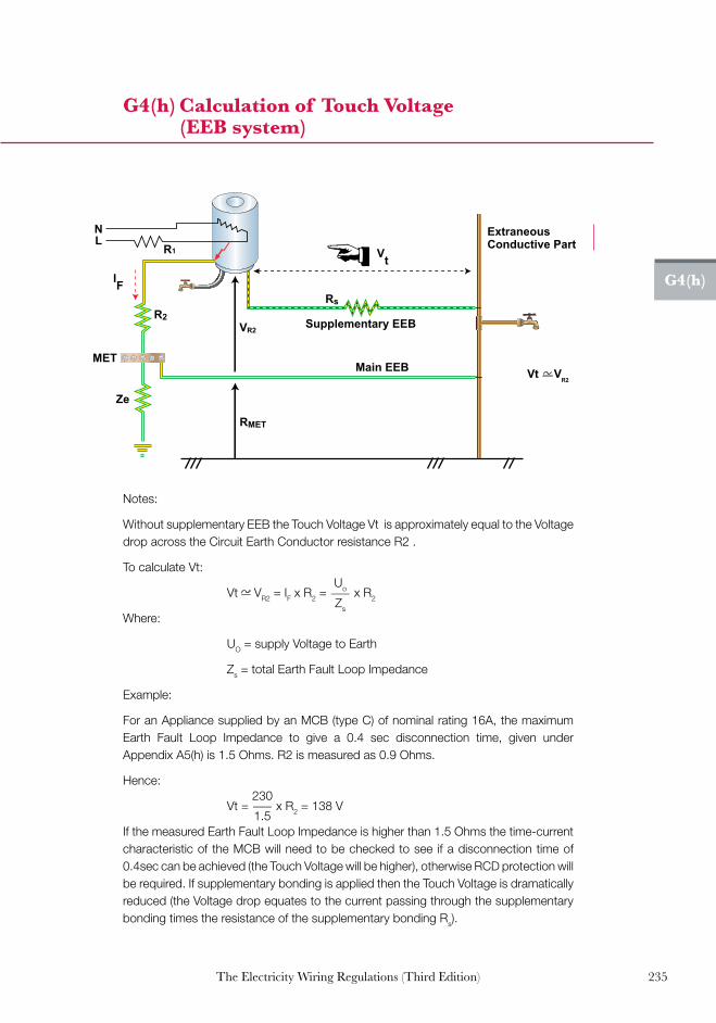
235The Electricity Wiring Regulations (Third Edition)
G4(h)
G4(h) Calculation of Touch Voltage (EEB system)
IF
MET
N
R2
RMET
Rs
Vt
VR2
R1 L
ExtraneousConductive Part
Supplementary EEB
Main EEB Vt VR2
Ze
Notes:
WithoutsupplementaryEEBtheTouchVoltageVtisapproximatelyequaltotheVoltagedropacrosstheCircuitEarthConductorresistanceR2.
TocalculateVt:
Vt VR2=IFxR2 = Uo___Zs
xR2
Where:
UO=supplyVoltagetoEarth
Zs=totalEarthFaultLoopImpedance
Example:
ForanAppliancesuppliedbyanMCB(typeC)ofnominalrating16A,themaximumEarth Fault Loop Impedance to give a 0.4 sec disconnection time, given underAppendixA5(h)is1.5Ohms.R2ismeasuredas0.9Ohms.
Hence:
Vt=230___1.5
xR2=138V
IfthemeasuredEarthFaultLoopImpedanceishigherthan1.5Ohmsthetime-currentcharacteristicoftheMCBwillneedtobecheckedtosee ifadisconnectiontimeof0.4seccanbeachieved(theTouchVoltagewillbehigher),otherwiseRCDprotectionwillberequired.IfsupplementarybondingisappliedthentheTouchVoltageisdramaticallyreduced(theVoltagedropequatestothecurrentpassingthroughthesupplementarybondingtimestheresistanceofthesupplementarybondingRs).

236 The Electricity Wiring Regulations (Third Edition)
G5(a)
These Regulations include a compulsory requirement for provision of Earth Leakage Protection (ELP) on all Final Circuits where Appliances may be used by any persons. This is normally achieved with RCD devices complying with BS EN 61008 and BS IEC 1008 which must operate within 200 ms at their residual current rating (tripping current) and within 40 ms at 5 times their residual current rating. RCDs must not operate at below 50% of their residual current rating. RCD devices with a residual operating current of 30 mA or less may be used for supplementary protection against Direct Contact, whilst devices rated above this value provide protection against Indirect Contact only (see clause 5.3.2).
ELP devices do not protect against electric shock between phase conductors or between phase and neutral nor do they provide any overload protection. The response of the human body depends on the time and magnitude of current that may pass at the time of an electric shock incident. The ‘low risk’ and ‘high risk’ range of current against time is illustrated below, along with the operating times of typical RCD devices (from IEC 60479).
G5(a) RCD operating characteristics and electric shock
1 2 3 4 3
IEC 60479 10,000
5,000
2,000
Tim
e in
mill
isec
onds
Current in milliamperes (RMS) Typical current limits
due to body resistance at 230V. 30mA RCD 100mA RCD
1,000
500
200
100
50
20
10 0.1 0.2 0.3 0.5 1 2 3 5 10 20 30 50
B A C1 C2 C3
100 200 300 500 1,000 2,000 3,000 5,000 10,000
Response of human body vs. RCD characteristics: Zone 1: usually no reaction Zone 2: shock sensation, but usually no harmful effects Zone 3: likelihood of muscular contraction, and temporary cardiac arrest without ventricular fibrillation Zone 4: in addition to the effects of zone 3, the probability of ventricular fibrillation is increased by 5% for curve C2 and 50% for curve C3; harmful effects such as cardiac arrest, breathing arrest and burns are likely to occur

237The Electricity Wiring Regulations (Third Edition)
G5(b)
G5(b) Typical values of body resistance and physiological effects
Human resistance for various skin contact conditions (k Ohms)
Toucharea Dry Wet
Finger touch 40–1,000 4–15
Handholdonwire 15–50 3–6
Hand hold on pipe 1–3 0.5–1.5
Palm touch 3–8 1–2
Internalbodyresistance(includingskin)=0.2–1kOhms
Electric current (1 second contact)
Physiological effect
Voltage required to produce the current with assumed
body resistance:
100 k Ohms(dry finger)
1 k Ohms(wet hand)
1mAThresholdoffeeling,tingling sensation
100V 1V
5mAAcceptedasmaximumharmless current
500V 5V
10-20mABeginningofsustainedmuscular contraction ("Can'tletgo"current)
1000V 10V
100-300mA
Ventricularfibrillation,fatalifcontinued.Respiratoryfunctioncontinues
10000V 100V

238 The Electricity Wiring Regulations (Third Edition)
G5(c)
RCD devices measure the vector sum of currents passing through the phase and neutral conductors in a circuit, via a magnetic coil and electronic amplifier.Thedevicewilltripif theseareoutof balancebymorethanthe residual operating current, in accordance with the manufacturer’s time-current performance curve. See Guidance Note G5(a).
The older type of voltage-operated earth leakage devices (ELCB) are not permitted (clause 5.4.2) since they operate by detecting fault voltage and require a connection between a Main Earth Conductor and an Earth Electrode; these devices are therefore vulnerable to maloperation due to parallel earth paths.
G5(c) RCD operating principle
Test button
Triprelay
Incoming supply
Triprelay
Incomingsupply
Loadcircuits
Loadcircuits
Test resistor
Test button
Test resistor
L
N
L
N
L3L2L1
NL3L2L1
N
Three-phase RCD:
Single-phase RCD:

239The Electricity Wiring Regulations (Third Edition)
G5(d)
Because of the use of semiconductor devices in an Electrical Installation there may be situations when an earth fault current is not purely sinusoidal but contains a d.c. or ‘chopped’ waveform. This may de-sensitise or disable standard a.c. operated RCDs. Special devices are available which are designed to continue to function for non-sinusoidal supply waveforms, complying with IEC1008, IEC1009 (indicated by the symbols shown below).
For RCD devices installed at a Main Distribution Boards, time delayed operation is usually required to avoid tripping when a fault occurs in aFinalCircuit (theFDBRCDshould tripfirst).TimedelayedRCDdevices are labelled ‘S type’.
For type B RCDs, they are able to provide protection in case of alternating residual sinusoidal currents up to 1000 Hz, pulsating direct residual currents and smooth direct residual currents. Refer to BS EN 62423 for more details.
G5(d) Types of RCDs
RCD
32A 100mAWRs122
ON
RCD
SGA 30mAWR5102
ON
normal ac sensitivityTYPE AC
pulsating dc sensitivityTYPE A
Reproduced with permission of Wylex / Electrium.
TYPE B

240 The Electricity Wiring Regulations (Third Edition)
G5(e)
G5(e) Sources of tripping of RCDs
Type of fault Reason
DownstreamofRCD
• DirectContactbypersons
• IndirectContact(duringearthfault)
• Incorrectdiscriminationwithupstream
anddownstreamdevices(e.g.between
MDBandFDB)
• Looseconnections
• Crossedneutralconnectionsonsplit
busbar distribution board
• Neutraltoearthfault
• HighEarthConductorcurrents(e.g.IT
equipment,filters,etc)
• MoistureinCircuitconductors
(especiallyjointsinMICCcables)
• MoistureinAppliances(e.g.cooker
heatingelement)
• Doublepoleswitching(capacitiveeffects)
• Transientvoltagescausedbylarge
inductiveloads(e.g.industrialmotors)
• DamagedCircuits(e.g.nailsinwalls)
UpstreamofRCD
•Looseconnections
•Mainsbornedisturbances(e.g.surges,
lightning,harmonics,transientsfromoverhead
lines)
•Disturbingloads(e.g.machinery,lift
motor,etc)
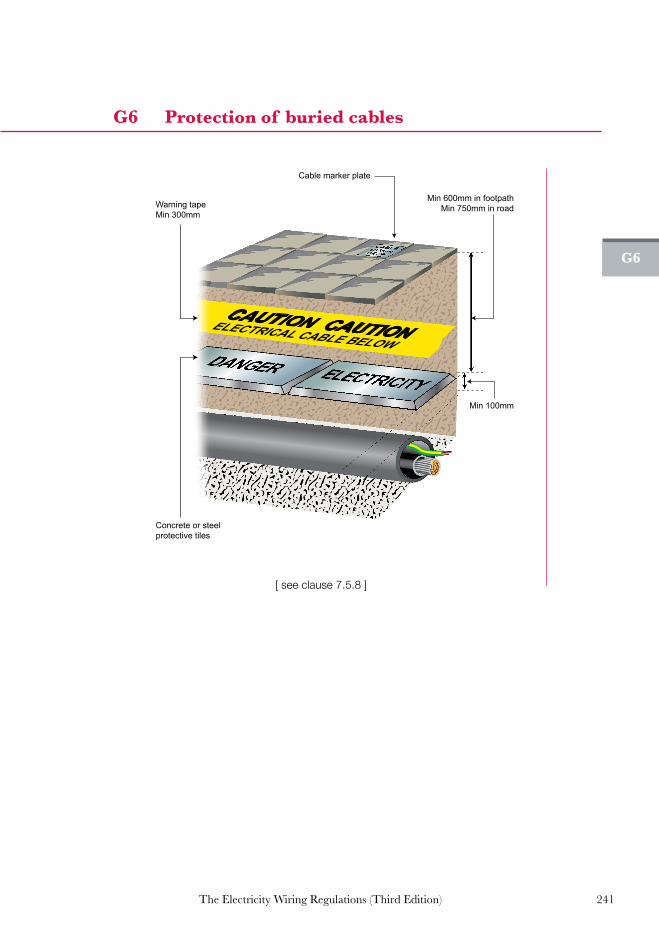
241The Electricity Wiring Regulations (Third Edition)
G6
G6 Protection of buried cables
CAUTION CAUTIONELECTRICAL CABLE BELOW
Cable marker plate
Min 600mm in footpathMin 750mm in road
Min 100mm
Concrete or steelprotective tiles
Warning tapeMin 300mm
[seeclause7.5.8]

242 The Electricity Wiring Regulations (Third Edition)
G7(a)
G7(a) Exposed unsheathed cables at termination points
[seeclauses7.4.8and7.5.12]

243The Electricity Wiring Regulations (Third Edition)
G7(b)
G7(b) Protection of high temperature connections
Fixedconduit
Clearance 50mm to frontcover of wall face unlesscarried out in galvanisedconduit
50 mm
Porcelain connector, in conduit box to changefrom fixed wiring toflexible connection
High temperature cableconnection or hightemperature sleeving toprotect flexible cableconnections
Conduit box withextension box to bringcontainment flush withwall construction
Wall Light Connection
Heat resistant sleeve required for
high temperature connections
[ see clause 7.5.17 ]

244 The Electricity Wiring Regulations (Third Edition)
G7(c)
G7(c) Weather protected outdoor socket-outlets
IP55 weather protected socketoutlet with 30mA RCD
30mA
PUSHTEST
[seeclauses7.1.14,9.4.1(b),9.5.1(b)and9.6.2(i)]

245The Electricity Wiring Regulations (Third Edition)
G7(d)
G7(d) Earth tails in Accessories and connection boxes
Double socket-outlet
Light switch
[seeclause6.6.4]

246 The Electricity Wiring Regulations (Third Edition)
G7(e)
G7(e) Minimum depth of buried plastic conduit
Min 50mm
Buriedplasticconduitsinwallsorceilingsmustbemin50mmdepthormetalconduitmustbeused(seeclause7.4.6)

247The Electricity Wiring Regulations (Third Edition)
G7(f)
G7(f)CircuitidentificationnumbersonAccessories and Earth Conductors
FDB2-R1
(Circuit identification numbers,See clause 3.6.4,3.6.5)
Note: phase and neutral conductors should be in the same sequence.
FDB2-R5
FDB2-Y5
E1E2E3 N
1
N2
Note: phaseandneutralconductorsshouldbeinthesamesequence.
[seeclause6.5.3]

248 The Electricity Wiring Regulations (Third Edition)
G7(g)
G7(g) Missing grommets and sharp edges on Cable Tray
[ see clause 7.4.8 ]

249The Electricity Wiring Regulations (Third Edition)
G7(h)
G7(h) Cables in ceiling-voids
See clause 7.3.8 and 7.5.15
(flexible connections to be limited to 3m in length and securely fixed; ‘plug & fit’ connection systems may
be used after the main supply connection)
[seeclauses7.3.8and7.5.15]
(flexibleconnectionstobelimitedto3minlengthandsecurelyfixed;‘plug&fit’connectionsystemsmaybeusedafterthemainsupplyconnection)

250 The Electricity Wiring Regulations (Third Edition)
G7(i)
G7(i) Cable glands for Earthing of armoured cable
Earth conductor sizemust be in accordance with
Appendix A5(j)
Note: all glands should be mechanically and electrically sound, secured andtightenedusingtheappropriatetools.
[seeclause7.5.18]

251The Electricity Wiring Regulations (Third Edition)
G7(j)
G7(j) Earth continuity connections across Cable Tray and conduit
[seeclauses6.6.1and7.4.4]

252 The Electricity Wiring Regulations (Third Edition)
G7(k)
G7(k) Prohibited terminal blocks and taped connections
[seeclause7.5.16]

253The Electricity Wiring Regulations (Third Edition)
G7(l)
G7(l) Slotting of steel gland plates for single core cables
Slot
Steel Plate
Note: singlecorecablesinasteelenclosurewillcauseelectromagneticcurrentsin the steel and possible overheating. This can be avoided by ensuringthatanonferromagneticmaterialisusedaroundthecables(e.g.brassoraluminiumplate)orslotsarecutinthesteelbetweenthephaseconductors.
[seeclause7.5.11]

254 The Electricity Wiring Regulations (Third Edition)
G7(m)
G7(m) Flex-outlets
Flex-outlet plate(with fuse)
Flex-outlet plate(without fuse)
Flex-outlet (with switch and fuse)

255The Electricity Wiring Regulations (Third Edition)
G8
G8. Typical lighting Circuit installations
Conduit bushed and sealedinto rear of Luminaire
External Luminaire internal surface installation
Rear entry conduit boxwith bush & coupling
Ceiling rose for changefrom fixed to flexiblewiring system
Heat resistant flexiblecable connection toLuminaire
Screw fixing to structure
External Luminaire
Earth lead to conduit box
Conduit bushed and sealedinto rear of Luminaire
Clearance 50mm to frontcover of wall face unlesscarried out in galvanisedconduit
Earth lead to conduit box
Heat resistant flexiblecable connection toLuminaire
Screw fixing to structure
Ceiling rose above ceilingfor change from fixed toflexible wiring sysem
External Luminaire
External Luminaire concealed wiring
50mm
G8. Typical lighting circuit installations

256 The Electricity Wiring Regulations (Third Edition)
G8
G8. Continued...
G8. Continued...
Earth lead to conduit boxCeiling rose for changefrom fixed to flexiblewiring system, rosemounted directly overLuminaire to allow access
Heat resistant flexiblecable connection toLuminaire
Flexible cableclamp on Luminaire
Plasterboard ceilingwith timber backed support
Fixed conduit
Luminaire
Recessed downlight plasterboard ceiling
Luminaire
Recessed downlight suspended ceiling
Fixed conduit
Ceiling rose for changefrom fixed to flexiblewiring system
Flexible cableclamp on LuminaireSuspended ceilingwith timber backed support
Heat resistant flexiblecable connection to Luminaire
Earth lead to conduit box

257The Electricity Wiring Regulations (Third Edition)
G8
G8. Continued...
Note1: flexibleconduitstobefittedwithglandsatbothends.
Note2: connectionboxtobecompletewithconduitinletandflexiblecableclampoutlet.
Note3: connectionbox tobe suitably sized toallow removal throughLuminaireaperture.
G8. Continued...
Note 1: Flexible conduits to be fitted with glands at both ends.Note 2: Connection box to be complete with conduit inlet flexible cable clamp outlet.Note 3: Connection box to be suitably rated for high temperature installation.Note 4: Connection box to be fitted with porcelain connectors.Note 5: Connection box to be suitably sized to allow removal through Luminaire aperture.Note 6: Transformer/driver & connection box to be laid directly onto ceiling support carefully avoiding the heat generation from Luminaire.Note 7: Cables and flexible conduits are to have sufficient length to allow removal through the Luminaire aperture for inspection.
Porcelain connector, inchandelier ceiling roseor conduit box
Earth lead to conduit boxplasterboard ceiling
Galvanised conduits dropto rear entry conduit box. Extension box to be usedwhere finish is not flushwith ceiling
Supplemental rod suspensionwhere necessary
Fixed conduit
Flexible cable for chandelier
Chandelier
Chandelier connection
Flexible cableclamp on Luminaire
ELV/LED Luminaire
Connection box
Flexible conduit
Dome lidFixedconduit
Earth lead to conduit box
Heat resistant flexible cable Transformer/driver
High temperatureFlexible connectionPlasterboard ceilingWith timber backed support
Recessed ELV or LED downlight plasterboard ceiling

258 The Electricity Wiring Regulations (Third Edition)
G9
G9. Isolation and switching
Note1: allpumpsinthesetaretobeprovidedwithisolators.
Note2: remote stop switches or isolator on the control panel does not providesufficientmeansofisolationtomeettherequirementsoftheRegulations.
Note3: remote stop push button must be located to be easily accessible butwithoutpossibilityofinadvertentoperation.
Note4: allcablesandconduitsmustbeadequatelysupportedandfullyterminated.
Note5: allisolatorsmustbelockableintheoffposition.
Note6: allmotorsmustbeprovidedwithsuitablysizedterminalblock.
G9. Isolation and switching
Flexible conduit finalconnection to pump
Fixed wiring connection toisolator. Typically conduitor steel wire armoured cables
Pump set control panel

259The Electricity Wiring Regulations (Third Edition)
G10(a)
1. Rooftapenetwork
2. EarthEquipotentialBondingto
roofmountedelectricalequipment
3. EarthEquipotentialBondingto
aerial array
4. MeshedtypeLPS
5. CatenarytypeLPS
6. Rod(Finial)typeLPS
7. Downconductor
8. EarthEquipotentialBondingbar
forinternalLPS
9. Testpoint
10.RingEarthElectrodebelowgroundlevel
11.EarthElectrode
12.EarthEquipotentialBondingring(for
buildingsabove30m,ringprovidedat
20mintervalsofheight)
13.EarthEquipotentialBondingtoliftshaft
14. EarthEquipotentialBondingto
façadesteelwork
15. EarthEquipotentialBondingto
buildingsteelwork
16. EarthEquipotentialBondingfrom
LVsupplytoequipotential
bondingbar.
17. Incomingsupplycable
18. Surgeprotectiondevice(SPD)
19. MDB
20. DB
21. UPS
22. ICTEquipment
23. Incomingcommunication
anddatacables(copper)
24. Satelliteaerialcable
25. SatelliteDecoder
26.Electricalsupplytoroofmounted
equipment
27.Sub-maincable
G10(a) Typical lightning protection system details
5
13
18
20
7
26
6
12
18
21 3
4
25
24
7
14
14
18
1814
7
14
14 14
119 9
15 27
19
8
16
23
1011
17
18
18
2120
22
11
18

260 The Electricity Wiring Regulations (Third Edition)
G10(a)
Note1: a riskassessmentevaluating the full requirementsof lightningprotectionsystems (LPS) including the impactonelectrical andelectronic systems(e.g.surgeprotectivedevices)istobecarriedoutbythedesigneroftheElectricalInstallation.
Note2: LPSmaybeprovidedinthreeways,meshed,catenaryorrodtype.Anyorallof theLPSsystemsshownabovemaybeuseddependingontheconfigurationofthePremises.OthermethodsmaybeproposedsubjecttotheapprovalbytheDistributionCompany.
Note3: down conductors are to be provided at a spacing interval to meetthe lightning protection risk assessment. Typically LPS I & II – 10 m,
LPSIII–15mandLPSIV–20masdetailedinBSEN62305-3.
Note4: theuseofnaturalcomponents(thebuildingreinforcementbarsorstructuralsteel), is not permitted unless approved by the Distribution Company.Down conductors are to be provided with test links either internally orexternally in accessible locations at low level. Earth Electrodes shouldideally be connected in a ring around the building at ground floor levelwherepractical.
Note5: structuralfoundationsorpilesmaybeusedaslightningEarthElectrodesanda typicaldetailedarrangement isprovided inG10(b). ForPremisesexceeding30minheight,secondaryringsshouldbeprovidedaroundthebuilding at a spacing of 20m intervals. Earth Equipotential Bonding isrequired for Extraneous-Conductive-Parts such as curtain wall framing,lift shaft steelwork, drainage and gutters, parapet copings, exposedequipment,handrailsetc.
Note6: surge protection devices (SPDs) are to be provided based on the riskassessment evaluation, but as a minimum should be deployed at theElectricity Intake to thePremises. Equipment that is prone to potentialdamagefromlightningstrikesshouldalsobeprotected.
G10(a) Continued...

261The Electricity Wiring Regulations (Third Edition)
G10(b)
G10(b) Lightning Earth Electrodes
1
2
7
48
5 4
11
10
13
12
9
6
3
G10 (b) Typical lightning protection system details
Earth pit arrangement
Structural foundations or piles arrangements
Note1: whenusingpilesasthelightningprotectionEarthElectrodes,theplanningistobecarriedoutinconjunctionwiththedesignofthestructure.
Note2: structuralengineertoconfirmthatpilescanbeusedandthatclampingorweldingofrodsisacceptable.
Note3: whereweldingisused,minimumlengthofweldsmustbe50mm.
Note4: allLPSworksassociatedwiththeuseofpilesistobeinspectedpriortopouringofconcrete.
Note5: protective cover for tape/cable through ground to Earth Electrode notshownbutistobeprovided.
Note6: terminationatEarthElectrodetobecorrosionresistantorbetreated forelectrolyticaction.
Note7: where tape is run surface at low level, mechanical protection is to beprovided.Whereprotectionismetallicthisistobebondedtothetape.
1. Downconductor
2. Testclamp
3. Twintailedbondingconductors
4. BoltedEarthclamps
5. Weldedconnectiontoreinforcementbars
6. Wallconstruction
7. Pilecap
8. Pile
9. Testclampwithrecessed
accessible cover
10.LightningprotectionEarthpit
11.EarthElectrode
12.Lightningprotectiontape
13.Corrosiontreatedconnection

262 The Electricity Wiring Regulations (Third Edition)
G11
G11. Changes in the Third Edition (March 2014)
The following is a summary of the key changes incorporated into the Electricity Wiring Regulations (Third Edition). Any clauses that were changed are indicated by a red line throughout this publication.
1. The scope of the Regulations now includes all Electrical Installations in the Emirate of Abu Dhabi, including Premises not connected to the Distribution Companies’ networks (for e.g. off-grid worker camps running on their own generators).
2. Clarification of the purpose of these Regulations which is to address the requirements for LV Electrical Installations only. The requirements for HV installations are addressed in the Electricity Supply Regulations, Electricity Distribution Code and the relevant DistributionCompanies’standards/specifications.
3. Clarificationontheobligationof OwnersandassociatedLicensed Contractors under these Regulations.
4. A new clause is added to enable Owners of major developments to enter into an undertaking with the Distribution Company to self-certify the design of their Electrical Installations. In such cases, there will be no requirement for the design to be approved by the Distribution Company before commencement of construction.
5. Enhancement of the requirements for the protection of electric shock from indirect contact by requiring the use of both the Earth Leakage Protected System (ELPS) and the Earth Equipotential Bonded System (EEBS).
6. New sections introduced to address External Lighting in Premises, Electrical Installations in Marinas or similar locations and solar PV systems.
7. Clarification that air-conditioning units, motors, large electrical machines,fluorescentordischargelighting,etc,shallbeprovided with power factor correction by a selection of equipment including variable speed drives, integral capacitors, or other suitable methods.
8. A new clause is added to prohibit the use of capacitor banks in residential villas.

263The Electricity Wiring Regulations (Third Edition)
9. Update of Guidance notes G2 on the estimation of Connected Load and the use of diversity factors for Final Circuits, SMDBs and MDBs.
10. Enhancement of the contents of the Appendices and Guidance notes to provide improved clarity. G11

264 The Electricity Wiring Regulations (Third Edition)
Notes

265The Electricity Wiring Regulations (Third Edition)
Notes
266 The Electricity Wiring Regulations (Third Edition)
Notes

267The Electricity Wiring Regulations (Third Edition)
Notes

268 The Electricity Wiring Regulations (Third Edition)
Notes

269The Electricity Wiring Regulations (Third Edition)
Notes

270 The Electricity Wiring Regulations (Third Edition)
Notes

271The Electricity Wiring Regulations (Third Edition)
Notes


Th
e Electricity W
iring R
egulation
s (Th
ird E
dition
)
The ElectricityWiring Regulations(Third Edition)
Issued by:The Regulation and Supervision Bureaufor the water, wastewater and electricity sectorin the Emirate of Abu DhabiThe Electricity Wiring Regulations (Third Edition)
March 2014
Pu
blication N
o. ED
/R01/010