the effects of the aerodynamic interaction on the
TRANSCRIPT

THE EFFECTS OF THE AERODYNAMIC INTERACTION ON
THE PERFORMANCE OF TWO FLETTNER ROTORS
G. Bordogna1, S. Muggiasca2, S. Giappino2, M. Belloli2, J.A. Keuning1, R.H.M. Huijsmans1 1Section of Ship Hydromechanics, Delft University of Technology, Mekelweg 2, 2628 CD, Delft, The
Netherlands 2Department of Mechanical Engineering, Politecnico di Milano, Via La Masa 1, 20156, Milan, Italy
Final version published in: Journal of Wind Engineering & Industrial Aerodynamics 196
(2020). doi.org/10.1016/j.jweia.2019.104024
Abstract:
Flettner rotors are nowadays becoming a widespread solution for wind-assisted propulsion. To
increase the fuel savings of the ship on which they are installed, multiple devices are typically
used. However, in the performance estimate of these hybrid ships, it is currently assumed that
Flettner rotors operate independently, regardless of the number of devices employed and their
relative position on the ship’s deck. The present investigation deals with a wind-tunnel
experimental campaign aimed at understanding the aerodynamic interaction effects on the
performance of two similar Flettner rotors. The study indicates that the aerodynamic
performance of the two Flettner rotors is affected by their interaction, and, generally, this is
most noticeable when the devices are set closer to each other and when they are aligned with
the wind direction. It is demonstrated that, depending on the apparent wind direction, the layout
of the Flettner rotors on the ship’s deck has a remarked influence on the driving and heeling
force coefficients of the entire rig. Lastly, the velocity ratio is found to play a key role in the
determination of how the interaction affects the Flettner rotor aerodynamic performance.
NOMENCLATURE
𝐴𝑅 Aspect ratio, 𝐻/𝐷
AWA Apparent Wind Angle
𝐶𝐷 Drag coefficient, 𝐹𝐷/(0.5 ⋅ 𝜌 ⋅ 𝑉2 ⋅ 𝐻 ⋅ 𝐷)
𝐶𝐿 Lift coefficient, 𝐹𝐿/(0.5 ⋅ 𝜌 ⋅ 𝑉2 ⋅ 𝐻 ⋅ 𝐷)
𝐶𝑋 Driving force coefficient, 𝐹𝑋/(0.5 ⋅ ρ ⋅ 𝑉2 ⋅ 𝐻 ⋅ 𝐷)
𝐶𝑌 Heeling force coefficient, 𝐹𝑌/(0.5 ⋅ ρ ⋅ 𝑉2 ⋅ 𝐻 ⋅ 𝐷)
𝐷 Cylinder diameter
𝐷𝐸 Endplate diameter
𝐹𝐿 , 𝐹𝐷 Lift and drag force
𝐹𝑋 , 𝐹𝑌 Driving and heeling force
𝐻 Cylinder span
𝑘 Velocity ratio, 𝑈𝑡𝑎𝑛/𝑉
𝑅𝑒 Reynolds number, (V ⋅ D)/ν
𝑈𝑡𝑎𝑛 Cylinder tangential velocity
𝑉 Incoming flow velocity

𝑊𝐴 Wind angle in experiments on two Flettner rotors
𝜈 Kinematic viscosity of air
𝜌 Density of air
1 INTRODUCTION
In the context of wind-assisted propulsion, Flettner rotors are currently attracting increasing interest
as a viable technology to reduce the fuel consumption of commercial ships. The Flettner rotor is a
rotating cylinder that generates an aerodynamic lift due to the Magnus effect, and it owes its name to
German engineer Anton Flettner, who first introduced it in 1925 (Flettner, 1925). The physical
phenomena associated with Flettner rotors and, more broadly, to rotating cylinders, were studied quite
extensively over the past years. As a result of these research efforts, it was possible to identify the
influence of several parameters, as for example the velocity ratio, the endplate size, the aspect ratio
and the Reynolds number, on the aerodynamic performance of a single Flettner rotor. However, to
increase the fuel-saving potential of the designated vessel, in real-life applications, multiple Flettner
rotors are often used (see Fig. 1). The use of multiple Flettner rotors in a confined space as it is the
deck of a ship is likely to lead to a change in performance of each of the installed device due to their
aerodynamic interaction.
Fig. 1 The E-ship 1 is a wind-assisted ship equipped with four Flettner rotors
Although it is tenable that, in general, this situation would be the norm, this phenomenon is nowadays
largely neglected. In fact, the aerodynamic thrust generated by a set of Flettner rotors is now
commonly calculated as the simple arithmetic sum of the thrust produced by each of the installed
devices, i.e. the aerodynamic interaction effects are fully disregarded (Li et al., 2012), (Traut et al.,
2012), (Pearson, 2014), (Traut et al., 2014) and (De Marco et al., 2016). On the other hand, in other
cases in which the interaction effects are taken into account, an arbitrary reduction in aerodynamic
force is assumed. (Eggers, 2016), for example, assigns a reduction in lift force to the leeward Flettner
rotor when the ship is sailing in certain conditions in which the aerodynamic interaction effects are
assumed to be most relevant.
The reason for these simplifications in modelling the aerodynamic thrust generated by a set of Flettner
rotors is because, substantially, the literature lacks publications on this topic. This is also remarked
in (De Marco et al., 2016) and (Badalamenti, 2010). There are, in fact, numerous publications on the
phenomena associated with arrangements of two or more steady cylinders, whereas considerably
fewer studies focused on sets of rotating cylinders. As it will be argued herewith, in either case, the
literature currently available is of limited practical use for real-life Flettner rotor applications.
Due to its importance in many engineering fields, the problem of interference between two or more
steady cylinders in tandem, staggered or side-by-side arrangement, was largely studied during the
years. Comprehensive summaries on this topic can be found in (Zdravkovich, 2003) and in (Sumner,
2010), in which details on the forces and pressures of each cylinder are provided together with

extensive analyses of the flow pattern. The same research topic attracted considerable attention also
for problems related to wake-induced vibrations, see, for example, (Bearman, 2011), (Assi et al.,
2010) and (Diana et al., 2014), in which cases, the focus is on the dynamic response of the analyzed
structures. Although the current research shares the aim of studies on multiple steady cylinders, i.e.
how two or more cylinders interfere depending on their relative position, the forces and flow patterns
generated by rotating cylinders are not comparable to those of steady cylinders. The findings relative
to steady cylinders have, therefore, limited utility in the context of the present work.
Regarding studies on multiple rotating cylinders, considerable fewer publications can be found in the
literature. (Prandtl, 1926), joint with his extensive research on the single Flettner rotor, provided flow
visualizations of two side-by-side counterrotating cylinders. Unluckily, no results regarding the
interaction effects on the aerodynamic forces were reported. The research efforts of (Ueda et al.,
2003) and (Watson, 1995) deal with analytical solutions for two rotating cylinders in Stokes flows
and, in (Ueda et al., 2003), the drag coefficients are provided for several velocity ratios and gap
distances between cylinders. For the same type of flow, (Garzon et al., 2017) analytically calculated
the velocity field generated by an array of four rotating cylinders. The results for four different
rotation sets are compared with PIV measurements and show good agreement. (Sungnul, et al., 2009),
(Yoon et al., 2009) and (Fallah et al., 2011) conducted numerical studies on two counter-rotating
cylinders in side-by-side and staggered arrangement. The computations were carried out in laminar
flow, i.e. 𝑅𝑒 < 100, and the effects of the velocity ratios and the cylinders’ relative positions on the
lift and drag coefficients were computed. The studies agree in indicating that both the cylinders’
relative positions and velocity ratios strongly influence their lift and drag coefficients. On the other
hand, the work of (Guo et al., 2009) comprised a series of PIV measurements for Reynolds numbers
ranging between 425 < 𝑅𝑒 < 1130 and for velocity ratios 0 ≤ 𝑘 ≤ 4. The cylinders were set in a
side-by-side arrangement and, also in this case, they were counter rotating. The study does not include
any result regarding the effects of the aerodynamic interference on the cylinders’ lift and drag
coefficients. However, in line with (Sungnul, et al., 2009), (Yoon et al., 2009) and (Fallah et al.,
2011), the author concludes that the gap distance and the cylinders’ velocity ratios are important
parameters to determine the flow pattern. This is supported by the finding that the vortex shedding of
the cylinders is suppressed as the velocity ratio increases.
The characteristics of the numerical and experimental investigations carried out until today on
multiple rotating cylinders limit the applicability of the available literature to the present work. In
fact, the research efforts here discussed were typically conducted in the laminar or creeping flow
regime as well as using counter-rotating cylinders. A part to the flow regime that, for the scope of
this research it is a limit on its own, to generate positive thrust Flettner rotors typically spin in the
same direction.
In this scenario, the present study aims to be the first attempt in investigating the effects of the
interaction on the aerodynamic performance of multiple Flettner rotors. The experimental campaign
comprised two distinct series of experiments: first, tests on a single Flettner rotor were carried out in
order to establish a baseline for comparison. For these experiments, measurements of the velocity
field were also taken at several locations in the wake of the single Flettner rotor. At a later time, two
analogous Flettner rotors were tested for a range of different relative positions and velocity ratios. In
this series of tests, their lift and drag coefficients were measured and then compared to those of the
single Flettner rotor to investigate the effects of the aerodynamic interaction. These results were
eventually used to study the performance, expressed in terms of driving and heeling force coefficients,
of different Flettner rotor layouts when installed on the deck of a ship.
The present investigation, together with a previous study of the authors regarding the effect of the
Reynolds number on a Flettner rotor’s aerodynamic coefficients (Bordogna et al., 2019), aims at

gaining a better understating of the real-life performance of these devices when used on a ship for
wind-assisted propulsion.
2 EXPERIMENTAL SETUP
2.1 WIND TUNNEL AND FLOW CHARACTERISTICS
The experiments were carried out in the boundary layer test section of Politecnico di Milano wind
tunnel. The test section is 13.84 m wide, 3.84 m high and 35 m long. It has a standard turbulent
intensity 𝐼𝑢 = 2% and the boundary layer thickness is about 0.2 m. Considering the wind-tunnel
boundary layer and the height of the Flettner rotor bottom static endplate from the ground (see Fig.
3), it can be assumed that the Flettner rotors experienced a straight wind profile throughout the
experimental campaign.
Fig. 2 The two Flettner rotors in the boundary layer test section of Politecnico di Milano wind tunnel
The flow velocity, used to calculate all the aerodynamic coefficients, was measured with the wind-
tunnel pitot tube that is hung at a distance of 1.2 m from the ceiling (Fig. 2). All tests were conducted
at a wind speed of 𝑉 = 5 m/s, leading to a Reynolds number 𝑅𝑒 = 1.0 ⋅ 105. Nonetheless, some tests
were carried out at lower and higher Reynolds numbers. In fact, some experiments on the single
Flettner rotor were conducted at a wind speed 𝑉 = 3.5 m/s (𝑅𝑒 = 7.0 ⋅ 104) and 𝑉 = 10 m/s (𝑅𝑒 =1.8 ⋅ 105). No corrections were made due to blockage effects as the blockage ratio was less than 1%.
2.2 THE FLETTNER ROTOR
The Flettner rotor type used throughout the experimental campaign had a diameter 𝐷 = 0.3 m, a span
𝐻 = 1.5 m and an aspect ratio 𝐴𝑅 = 5, that is comparable to the aspect ratio of Flettner rotors
commonly used for wind-assisted propulsion. Two endplates, of diameter 𝐷𝐸/𝐷 = 2, were used. In
particular, the top endplate rotated with the cylinder while the bottom endplate was fixed at a height
of 0.3 m from the ground (Fig. 3).

Fig. 3 Main dimensions of the Flettner rotors used in the experiments
The rotating cylinder comprised three different main parts: a hollow square section beam welded to
a steel ground plate, an aluminium static cylinder and a thin steel rotating cylinder on top of which
the carbon fibre endplate was attached. The electric engine used to spin the cylinder was hung on a
plate secured to the top of the static cylinder. The rotation was passed to the external cylinder by
means of a flexible joint that connected the engine shaft with the top plate shaft, to which the external
rotating cylinder was bolted (Fig. 4).
Fig. 4 Flettner rotor components with ATI balances (a) and HBM load cells (b)
The two cylinders used in the experiments were analogous except for the measurement instruments
employed. In fact, one cylinder was equipped with two ATI Mini45 F/T balances, that are 6-axis
sensors, while the other with three HBM Z6FD1 load cells, that are monodirectional sensors. The
internal arrangement of the two cylinders, specifically the connection between the hollow beam and
the static cylinder, had to be modified to fit the different measurement instruments used. This is shown
in Fig. 4.
2.3 SINGLE FLETTNER ROTOR SETUP
During the experiments, the single Flettner rotor was positioned in the centre of the wind-tunnel turn
table and the lift and drag forces were measured for all velocity ratios considered. For velocity ratios
k = 0, k = 1, k = 1.5 and k = 2, moreover, measurements of the velocity field were taken at several
positions in the wake of the rotating cylinder.

Fig. 5 Vertical position of the Cobra Probes with respect to the Flettner rotor
Four Cobra Probes were used to measure the velocity field. The Cobra Probe is a multi-hole pressure
probe capable to measure the three velocity components within an angle range of ±45° at a frequency
of 2000 Hz. The Cobra Probes were mounted on a vertical bar at four different heights, namely 465
mm (Cobra 4), 850 mm (Cobra 3), 1235 mm (Cobra 2) and 1620 mm (Cobra 1) from the ground (Fig.
5). Measurements of the velocity field were taken at four longitudinal distances downstream the
Flettner rotor, corresponding to 1.5, 3, 7.5 and 15 diameters. At each longitudinal position, the vertical
bar was automatically displaced from -1.5 m to +1.5 m with respect to the cylinder centreline, in
steps of 150 mm.
For this series of tests, the Flettner rotor equipped with the ATI balances was used.
2.4 TWO FLETTNER ROTOR SETUP
The two Flettner rotors were tested for three different gap distances, defined as the longitudinal
distance from the cylinders’ vertical axes of symmetry (see Fig. 2), corresponding to 3, 7.5 and 15
diameters. For each gap distance, the wind-tunnel turn table was rotated at various angles between
15° and 180° in order to change the cylinders’ relative position with respect to the incoming wind
direction.
Fig. 6 Conventions used for the two-Flettner rotor experiments for wind angles < 90° (left) and wind angles > 90° (right)
For each case, the Flettner rotors were spun for all combinations of velocity ratios generated by k =1, k = 1.5 and k = 2, leading to a matrix of nine velocity ratios. Throughout the experiments, the
cylinders rotated clockwise and the lift and drag forces of Flettner rotor A and Flettner rotor B were
measured following the conventions depicted in Fig. 6.
2.5 MEASUREMENT UNCERTAINTY
The uncertainty of the experimental study was calculated according to the ISO “Guide to the
Expression of Uncertainty in Measurement” (ISO/IEC 98-3, 2008). The expanded uncertainty with

95% confidence level, 𝑢95, was calculated from the standard uncertainty related to the measurement
precision, 𝑢𝑝𝑟, and the standard uncertainty of the bias errors of the measurement instruments, 𝑢𝑏𝑖𝑎𝑠.
During the experiments, repetitions were carried out exclusively for k = 1, k = 1.5 and k = 2, and
for Reynolds number 𝑅𝑒 = 1.0 ⋅ 105. The measurement uncertainties were therefore calculated for
these conditions. The standard uncertainty related to the measurement precision reads:
𝑢𝑝𝑟 = √(𝜎2/𝑁) (1)
where 𝜎 is the standard deviation of the 𝑁 considered data points.
On the other hand, the standard uncertainty related to the bias errors of the measurement instrument
is the sensitivity of the measurement instrument accuracy, obtained by means of calibration tests,
respect to the quantity of interest. ubias can then be calculated by taking the partial derivative of the
instrument accuracy with respect to the quantity to be analysed. The value of ubias differ for the ATI
balance and the HBM load cell. The expanded uncertainty with 95% confidence level is thus
calculated according to:
𝑢95 = 𝑐 ⋅ √(𝑢𝑝𝑟2 + 𝑢𝑏𝑖𝑎𝑠
2 ) (2)
where the coverage factor 𝑐 is set to 𝑐 = 2.
Regarding the tests on the two Flettner rotors, it should be pointed out that repetitions were not carried
out for the entire set of gap distances and flow angles analysed. In fact, for each considered velocity
ratio, the tests were repeated only for one gap distance and one flow angle. The assumption is that the
measurement uncertainties calculated for those conditions can also be applied to all other comparable
conditions, i.e. same velocity ratio but different gap distance and different flow angle. This is
justifiable because the measurement precision error appears to be marginal compared to the bias error
of the measurement instrument. This is particularly the case for the HBM load cells, for which the
bias error appears to be considerably large. The reason of a large bias error is due to the fact that the
measurement instruments chose for the current experiments had to have a sufficiently large load range
along the vertical axis to withstand the weight of the Flettner rotor but, consequently, the load ranges
along the lift and drag axes resulted to be over-dimensioned. One possibility to reduce the
measurement instrument bias error would have been to increase the wind speed at which the
experiments were carried out. However, in the current experimental campaign, this was not feasible
because, to reach the desired velocity ratios, the Flettner rotors should have spun at much higher
rotational speeds, and this was a concern for the structural limits of the Flettner rotor assembly with
respect to vibrations. In fact, it was decided to establish a safety limit of 11 Hz (the lowest
eigenfrequency of the Flettner rotor assembly was 16 Hz), meaning that to reach velocity ratio k = 2
the highest achievable wind speed was 𝑉 = 5 m/s.
The uncertainties derived with the method herewith described are included in the results in the form
of error bars. For the sake of clarity, the error bars are given just for one data point for each setup
(single and double Flettner rotor setup) and for each quantity of interest (𝐶𝐿, 𝐶𝐷, 𝐶𝑋 and 𝐶𝑌). This is
sufficient to understand the magnitude of the uncertainties with respect to the relative measurements
because, as previously explained, the standard uncertainty related to the measurement precision 𝑢𝑝𝑟,
that depends on the different testing conditions (i.e. wind angle, gap distance, velocity ratio), is
negligible compared to ubias. Moreover, regarding the driving and heeling force coefficients, for
which the results are presented for the entire Flettner rotor rig, the measurement uncertainties were
calculated as the summation in quadrature of 𝑢95 of Flettner rotor A and 𝑢95 of Flettner rotor B. The
measurement uncertainties of the single Flettner rotor, on the other hand, are calculated for all

considered conditions using ubias relative to the ATI balance, since it was the measurement
instrument employed in the single Flettner rotor experiments.
3 RESULTS
3.1 RESULTS OF THE SINGLE FLETTNER ROTOR
This section deals with the results of the experiments carried out on the single Flettner rotor. The aim
of these tests was twofold: on one hand, the force measurements were necessary to create reference
data for the comparison with the results of the double Flettner rotor tests whereas, on the other hand,
the measurements of the velocity field provided a useful insight to understand the nature of the
aerodynamic interaction effects. As already mentioned in Section 2.1, the tests were carried out at
𝑅𝑒 = 105, however, experiments at 𝑅𝑒 = 7.0 ⋅ 104 and at 𝑅𝑒 = 1.8 ⋅ 105 were also performed. In
the former case, the reason was to better compare the results of the single Flettner rotor with the
available literature data. In the latter case, the aim was to investigate, within the possibilities offered
by the setup employed, whether a higher Reynolds number would affect the lift and drag coefficients
in the same manner described in a previous publication of the authors (Bordogna et al., 2019).
The direction of rotation and the reference system used during the single Flettner rotor experiments
are depicted in Fig. 7.
Fig. 7 Direction of rotation and reference system used for the single Flettner rotor tests
In Fig. 8, the results of the single Flettner rotor are provided and compared with the results of
(Badalamenti et al., 2008), who performed tests at Reynolds number 𝑅𝑒 = 1.9 ⋅ 104 on a Flettner
rotor of similar aspect ratio (𝐴𝑅 = 5.1), and using a similar configuration (one rotating and one fixed
endplate of 𝐷𝐸/𝐷 = 2). Although due to the setup used in the current work, it was unfeasible to reach
such a low Reynolds number, the results of the current experiments obtained at 𝑅𝑒 = 7.0 ⋅ 104 show
an excellent agreement with the results of (Badalamenti et al., 2008).
Fig. 8 Lift and drag coefficients of the single Flettner rotor compared with the results of (Badalamenti et al., 2008)

The differences between the results obtained at lower and higher Reynolds numbers are in line with
the findings of (Bordogna et al., 2019).
The results of the velocity field measurements obtained at velocity ratios k = 0, k = 1, k = 1.5 and
k = 2 are given in Fig. 9. For the sake of conciseness, only the results of Cobra probe 2 are reported.
The results of Cobra probe 2 and Cobra probe 3, in fact, show a similar trend and they can be
considered representative for most of the cylinder’s span. Cobra probe 1 and Cobra probe 4, on the
other hand, captured a more peculiar trend due to their position closer to the Flettner rotor top and
bottom tip vortices (see Fig. 5).
Fig. 9 Velocity field past the single Flettner rotor at different velocity ratios
The results depicted in Fig. 9 illustrate the mean velocity magnitude and the mean direction of the
flow. The velocity magnitude, that is normalized with the free stream velocity, is indicated by the
colourmap and the vector size. Conversely, the direction of the flow is suggested by the vector
orientation. The results are given in terms of longitudinal (x-axis) and transversal (y-axis) distance
from the cylinder’s vertical axis of symmetry, normalized with the cylinder diameter. The Flettner
rotor rotates clockwise as shown in Fig. 7, and it is located at the centre of the reference system
(x/D = 0, y/D = 0). As it can be appreciated from the results, the cylinder wake, that is clearly visible
for k = 0, is reduced with the increase of the velocity ratio. At k = 1, the wake is already strongly
reduced and deviated due to the downwash caused by the Flettner rotor’s circulation. At k = 2, the
wake is fully suppressed and the flow is heavily deviated, up to an angle of about 40° at the distance
x/D = 1.5. It should also be noted that, in general, the downwash is mainly appreciable in the range
−3 < y/D < 3 and that, in the range 1 < y/D < 4, the circulation causes the flow speed to increase
compared to the free stream velocity. Higher velocity ratios mean a stronger circulation and, in turn,
this leads to a more noticeable downwash and a more steep increase in wind speed in the range 1 <y/D < 4. On the other hand, the circulation does not seem to cause any appreciable decrease in flow
speed on the opposite side of the cylinder, in the range −1 < y/D < −4, where, in fact, the flow
appears to have a speed comparable to the free stream velocity.

3.2 RESULTS OF TWO FLETTNER ROTORS
3.2.1 LIFT AND DRAG COEFFICIENTS
The lift and drag coefficients of the two Flettner rotors were measured for several wind angles ranging
between 15° and 180° (see conventions in Fig. 6) to investigate the influence of different relative
positions with respect to the incoming wind on the cylinders’ aerodynamic coefficients. Depending
on the gap distance, different wind angles were tested. These are reported in Table 1.
Gap distance Wind angles
[deg]
3 D 15 30 45 60 90 120 150 180
7.5 D 15 30 45 60 90 120 150 180
15 D 15 30 - 60 - 120 150 180
Table 1 Summary of the wind angles tested depending on the considered gap distance
The reason why no experiments were conducted for gap distance 15D and wind angle 𝑊𝐴 = 90°, is
because, in this condition, the Flettner rotor positioned closer to the edge of the turn table would have
been too near the wind-tunnel walls and this, arguably, would have jeopardized the measurements.
Moreover, for the largest gap distance, it was decided not to perform experiments at 𝑊𝐴 = 45°.

Fig. 10 Lift and drag coefficients for Flettner rotor A (left) and Flettner rotor B (right) for velocity ratio of interest 𝑘 = 1
For each considered gap distance and wind angle, the experiments on the two Flettner rotors
comprised a matrix of nine tests generated by all combinations of velocity ratios k = 1, k = 1.5 and
k = 2. During the experiments, in fact, one Flettner rotor spun at a given velocity ratio, while the
other spun for the entire set of velocity ratios k = 1, k = 1.5 and k = 2. Lift and drag were measured
for all velocity ratio combinations. The results reported in Fig. 10, Fig. 11 and Fig. 12 are also
structured in this manner. In fact, the results for Flettner rotor A and Flettner rotor B show how, for
the velocity ratio of interest, their lift and drag coefficients change due to the velocity ratio of the
other Flettner rotor. The results of the single Flettner rotor used for the comparison are also reported
for the same velocity ratio of interest. Following the conventions depicted in Fig. 6, when analyzing
the results, it should be borne in mind that Flettner rotor A is windward with respect to Flettner rotor
B until 𝑊𝐴 = 90°, whereas the opposite is true for wind angles 𝑊𝐴 > 90°.

Fig. 11 Lift and drag coefficients for Flettner rotor A (left) and Flettner rotor B (right) for velocity ratio of interest 𝑘 = 1.5
The results given in Fig. 10, Fig. 11 and Fig. 12 show that the Flettner rotors’ relative position has a
considerable influence on how 𝐶𝐿 and 𝐶𝐷 are affected by the aerodynamic interaction. This is in
agreement with the findings of the literature discussed in Section 1. It appears evident, in fact, that,
generally, the effects of the Flettner rotors’ aerodynamic interaction become less pronounced with
the increase of the gap distance. This holds true for any considered velocity ratio of interest.
Moreover, the position of the two Flettner rotors with respect to the incoming wind direction, i.e. the
wind angle, also appears to play an important role. When the two cylinders come close to being
aligned with the incoming wind direction, in fact, 𝐶𝐿 and 𝐶𝐷 of the downstream Flettner rotor are
strongly influenced by the interaction effects. This can be noticed looking at the results of Flettner
rotor A for 150° ≤ 𝑊𝐴 ≤ 180° as well as those of Flettner rotor B for 15° ≤ 𝑊𝐴 ≤ 30°. In these
wind angle ranges, in fact, the downstream Flettner rotor is, at least partially, immersed in the wake
generated by the upstream one and these are, generally, the regions where the most prominent
variations of lift and drag coefficients occur. As suggested by the results of the velocity field
measurements shown in Fig. 9, the variations of lift and drag coefficients are mainly caused by two
phenomena: a change of the incoming flow velocity and a change in direction of the flow. The
magnitude of these phenomena depends on the velocity ratio, that, therefore, is the key parameter that
regulates how the aerodynamic interaction affects the Flettner rotor lift and drag coefficients. For
example, when Flettner rotor A is in the wake of Flettner rotor B, i.e. 150° ≤ 𝑊𝐴 ≤ 180°, its 𝐶𝐿
decreases while its 𝐶𝐷 increases. Although to a different extent, this is the case for all gap distances
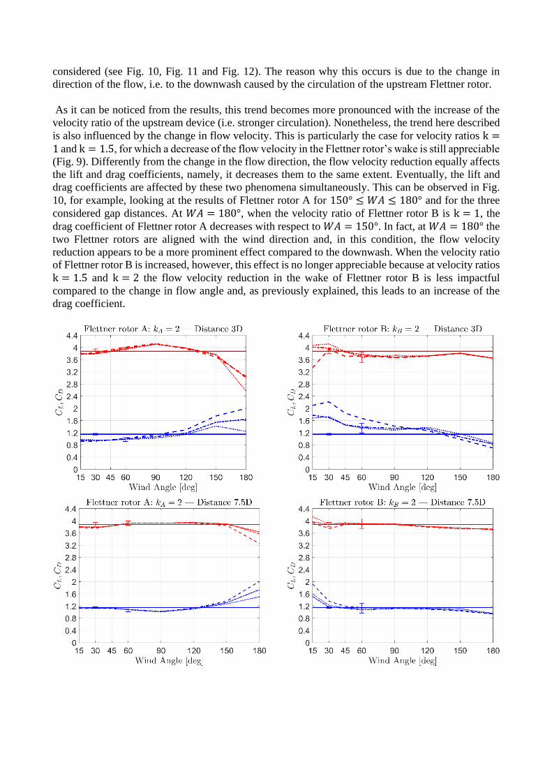
considered (see Fig. 10, Fig. 11 and Fig. 12). The reason why this occurs is due to the change in
direction of the flow, i.e. to the downwash caused by the circulation of the upstream Flettner rotor.
As it can be noticed from the results, this trend becomes more pronounced with the increase of the
velocity ratio of the upstream device (i.e. stronger circulation). Nonetheless, the trend here described
is also influenced by the change in flow velocity. This is particularly the case for velocity ratios k =1 and k = 1.5, for which a decrease of the flow velocity in the Flettner rotor’s wake is still appreciable
(Fig. 9). Differently from the change in the flow direction, the flow velocity reduction equally affects
the lift and drag coefficients, namely, it decreases them to the same extent. Eventually, the lift and
drag coefficients are affected by these two phenomena simultaneously. This can be observed in Fig.
10, for example, looking at the results of Flettner rotor A for 150° ≤ 𝑊𝐴 ≤ 180° and for the three
considered gap distances. At 𝑊𝐴 = 180°, when the velocity ratio of Flettner rotor B is k = 1, the
drag coefficient of Flettner rotor A decreases with respect to 𝑊𝐴 = 150°. In fact, at 𝑊𝐴 = 180° the
two Flettner rotors are aligned with the wind direction and, in this condition, the flow velocity
reduction appears to be a more prominent effect compared to the downwash. When the velocity ratio
of Flettner rotor B is increased, however, this effect is no longer appreciable because at velocity ratios
k = 1.5 and k = 2 the flow velocity reduction in the wake of Flettner rotor B is less impactful
compared to the change in flow angle and, as previously explained, this leads to an increase of the
drag coefficient.
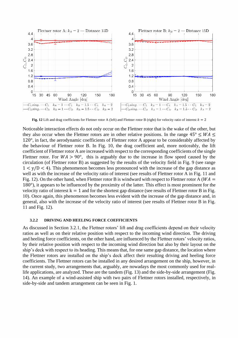
Fig. 12 Lift and drag coefficients for Flettner rotor A (left) and Flettner rotor B (right) for velocity ratio of interest 𝑘 = 2
Noticeable interaction effects do not only occur on the Flettner rotor that is the wake of the other, but
they also occur when the Flettner rotors are in other relative positions. In the range 45° ≤ 𝑊𝐴 ≤120°, in fact, the aerodynamic coefficients of Flettner rotor A appear to be considerably affected by
the behaviour of Flettner rotor B. In Fig. 10, the drag coefficient and, more noticeably, the lift
coefficient of Flettner rotor A are increased with respect to the corresponding coefficients of the single
Flettner rotor. For 𝑊𝐴 > 90°, this is arguably due to the increase in flow speed caused by the
circulation (of Flettner rotor B) as suggested by the results of the velocity field in Fig. 9 (see range
1 < y/D < 4). This phenomenon becomes less pronounced with the increase of the gap distance as
well as with the increase of the velocity ratio of interest (see results of Flettner rotor A in Fig. 11 and
Fig. 12). On the other hand, when Flettner rotor B is windward with respect to Flettner rotor A (𝑊𝐴 =180°), it appears to be influenced by the proximity of the latter. This effect is most prominent for the
velocity ratio of interest k = 1 and for the shortest gap distance (see results of Flettner rotor B in Fig.
10). Once again, this phenomenon becomes less evident with the increase of the gap distance and, in
general, also with the increase of the velocity ratio of interest (see results of Flettner rotor B in Fig.
11 and Fig. 12).
3.2.2 DRIVING AND HEELING FORCE COEFFICIENTS
As discussed in Section 3.2.1, the Flettner rotors’ lift and drag coefficients depend on their velocity
ratios as well as on their relative position with respect to the incoming wind direction. The driving
and heeling force coefficients, on the other hand, are influenced by the Flettner rotors’ velocity ratios,
by their relative position with respect to the incoming wind direction but also by their layout on the
ship’s deck with respect to its heading. This means that, for one same gap distance, the location where
the Flettner rotors are installed on the ship’s deck affect their resulting driving and heeling force
coefficients. The Flettner rotors can be installed in any desired arrangement on the ship, however, in
the current study, two arrangements that, arguably, are nowadays the most commonly used for real-
life applications, are analyzed. These are the tandem (Fig. 13) and the side-by-side arrangement (Fig.
14). An example of a wind-assisted ship with two pairs of Flettner rotors installed, respectively, in
side-by-side and tandem arrangement can be seen in Fig. 1.

Fig. 13 Flettner rotors installed on the ship in tandem arrangement. Conventions for 𝐴𝑊𝐴 < 90° (left) and 𝐴𝑊𝐴 > 90° (right)
The driving and heeling force coefficients are calculated from the lift and drag coefficients according
to Eq. 3 and Eq. 4:
CX = CL ⋅ sin(AWA) − CD ⋅ cos(AWA) (3)
CY = CL ⋅ cos(AWA) + CD ⋅ sin(AWA) (4)
where, in this context, the apparent wind angle 𝐴𝑊𝐴, is the angle between the incoming wind
direction and the heading of the ship.
Fig. 14 Flettner rotors installed on the ship in side-by-side arrangement: conventions for 𝐴𝑊𝐴 < 90° (left) and 𝐴𝑊𝐴 > 90° (right)
Due to the setup used during the experiments on the two Flettner rotors (see Fig. 6), the driving and
heeling force coefficients were calculated for a different set of apparent wind angles depending on
the type of arrangement considered. These are reported in Table 2.
Arrangement type Apparent wind angles
[deg]
Tandem 30 45 60 90 120 150 180 -
Side by side 30 60 90 105 120 135 150 180
Table 2 Apparent wind angles at which 𝐶𝑋 and 𝐶𝑌 are calculated depending on the Flettner rotor arrangement
The present section aims at investigating the influence of the aerodynamic interaction on the
performance of the considered Flettner rotor arrangements with respect to similar sets for which the
interaction effects are neglected. To do so, the driving and heeling force coefficients are calculated
according to Eq. 5 and Eq. 6 for the combination of the two Flettner rotors belonging to one same

arrangement. These coefficients are then compared with those obtained for an analogous arrangement
composed of two non-interacting devices whose data are derived from the results of the single Flettner
rotor experiments.
CX = (𝐶𝑋𝐴+ CXB
)/2 (5)
C𝑌 = (𝐶𝑌𝐴+ C𝑌B
)/2 (6)
Considering the most common Flettner rotor installations currently in existence, the driving and
heeling force coefficients when the two devices are in tandem arrangement are calculated for the three
gap distances tested during the experiments. Conversely, when the Flettner rotors are in side-by-side
arrangement, 𝐶𝑋 and 𝐶𝑌 are calculated only for the shortest gap distance.
Fig. 15 - Fig. 18 show the results of the present analysis. Each case is investigated both in terms of
𝐶𝑋 and 𝐶𝑌 coefficients and in terms of percentage change with respect to the case of two non-
interacting Flettner rotors. For the sake of conciseness, for each gap distance and arrangement type,
only the most relevant results are reported herewith.
In Fig. 15 and Fig. 16 the results of the two Flettner rotors placed at a distance of three diameters are
given. For this condition, the most noticeable finding is that the driving and heeling force coefficients
largely differ depending on whether the devices are installed in tandem or side-by-side arrangement.
In fact, when the two Flettner rotors are in tandem arrangement the most relevant interaction effects
occur when the ship is sailing close hauled (𝐴𝑊𝐴 = 30°) or downwind (𝐴𝑊𝐴 = 180°). Conversely,
for the side-by-side installation, the most evident interaction effects occur when the ship is sailing
beam reach (90° ≤ 𝐴𝑊𝐴 ≤ 120°). The magnitude of the interaction effects can be better appreciated
by looking at the percentage change graphs reported at the bottom of the corresponding 𝐶𝑋 and 𝐶𝑌
results.
Fig. 15 Driving and heeling force coefficients (top) and their percentage change with respect to the non-interacting Flettner rotors
(bottom), for two different sets of velocity ratios. Devices installed in tandem arrangement at a gap distance of 3 diameters

Another substantial finding is that, for the same set of velocity ratios, the aerodynamic performance
of the Flettner rotor ensemble varies depending on whether the windward Flettner rotor spins faster
than the leeward one, or vice versa. This is evident, for example, for the side-by-side arrangement
when the Flettner rotors spin at velocity ratios k = 1 and k = 1.5 and the apparent wind angle is
𝐴𝑊𝐴 = 105° (Fig. 16). In this condition, if the windward device (Flettner rotor A) spins at a higher
velocity ratio than the leeward one (Flettner rotor B), the driving force coefficient of the Flettner rotor
ensemble increases by nearly 20% with respect to the non-interacting Flettner rotors. On the other
hand, this gain does not occur when Flettner B spins faster than Flettner rotor A.
Fig. 16 Driving and heeling force coefficients (top) and their percentage change with respect to the non-interacting Flettner rotors
(bottom), for two different sets of velocity ratios. Devices installed in side-by-side arrangement at a gap distance of 3 diameters
With the exception of the largest gap distance, and in particular for the tandem arrangement, the
interaction effects occurring between the two Flettner rotors at apparent wind angles 𝐴𝑊𝐴 < 45°
worsen the aerodynamic efficiency of the entire rig, i.e. 𝐶𝑋 decreases and 𝐶𝑌 increases. This is due to
the decrease in 𝐶𝐿 and the increase in 𝐶𝐷 of the leeward Flettner rotor due to the downwash generated
by the windward device (see relative figures in Section 3.2.1). The same phenomenon, however, often
has a positive effect on the overall performance of the rig when the apparent wind angle is 𝐴𝑊𝐴 =180°. This can be appreciated, for example, in Fig. 15 when both devices spin at velocity ratio k = 2
as well as in Fig. 17 for velocity ratios k = 1.5 and k = 2. In these conditions, in fact, the decrease
in 𝐶𝐿 and increase in 𝐶𝐷 of the leeward Flettner rotor causes a rise of the driving force coefficient and
a reduction of the heeling force coefficient of the Flettner rotor ensemble.
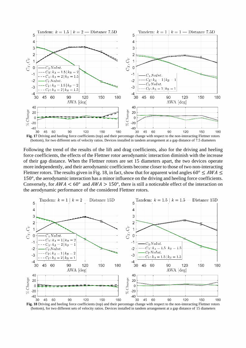
Fig. 17 Driving and heeling force coefficients (top) and their percentage change with respect to the non-interacting Flettner rotors
(bottom), for two different sets of velocity ratios. Devices installed in tandem arrangement at a gap distance of 7.5 diameters
Following the trend of the results of the lift and drag coefficients, also for the driving and heeling
force coefficients, the effects of the Flettner rotor aerodynamic interaction diminish with the increase
of their gap distance. When the Flettner rotors are set 15 diameters apart, the two devices operate
more independently, and their aerodynamic coefficients become closer to those of two non-interacting
Flettner rotors. The results given in Fig. 18, in fact, show that for apparent wind angles 60° ≤ 𝐴𝑊𝐴 ≤150°, the aerodynamic interaction has a minor influence on the driving and heeling force coefficients.
Conversely, for 𝐴𝑊𝐴 < 60° and 𝐴𝑊𝐴 > 150°, there is still a noticeable effect of the interaction on
the aerodynamic performance of the considered Flettner rotors.
Fig. 18 Driving and heeling force coefficients (top) and their percentage change with respect to the non-interacting Flettner rotors
(bottom), for two different sets of velocity ratios. Devices installed in tandem arrangement at a gap distance of 15 diameters

4 INFLUENCE OF REYNOLDS NUMBER ON THE INTERACTION EFFECTS
As discussed in Section 2.1, the experiments to investigate the aerodynamic interaction were carried
out at Reynolds number 𝑅𝑒 = 1.0 ⋅ 105, meaning that the flow experienced by the two Flettner rotors
was in the subcritical regime. As demonstrated in (Bordogna et al., 2019), however, the Reynolds
number influences the drag and, within certain conditions, the lift coefficient of a Flettner rotor.
Arguably, it should be expected that this also plays a role in the way multiple Flettner rotors interact
with each other. To investigate whether this is the case, during a previous experimental campaign
conducted on a large-scale Flettner rotor (Bordogna et al., 2019), measurements of the velocity field
were taken in the wake of the analysed rotating cylinder. The large-scale Flettner rotor had a diameter
𝐷 = 1.0 m and a span 𝐻 = 3.73 m. Due to its span and considering that the experiments took place
in the same test section described in Section 2.1, the tip vortices were suppressed and, in this sense,
the tests can be deemed two-dimensional. See (Bordogna et al., 2019) for further details. The velocity
field was measured using the same type of equipment described in Section 2.3, however, in this case,
being the flow two-dimensional, measurements were only taken at the Flettner rotor mid-span height.
Tests were carried out for two Reynolds number, namely 𝑅𝑒 = 2.5 ⋅ 105 (critical regime) and 𝑅𝑒 =5.5 ⋅ 105 (supercritical regime), and for three different velocity ratios, i.e. k = 1, k = 2 and k = 3.
Following the same conventions used in Fig. 9, the results of the velocity field measurements are
reported in terms of mean velocity magnitude and mean direction of the flow. The velocity magnitude,
that is normalized with the free stream velocity, is indicated by the colourmap and the vector size. On
the other hand, the direction of the flow is suggested by the vector orientation. Also for the results
reported in Fig. 19 it should be assumed that the Flettner rotor is located at the centre of the reference
system (x/D = 0, y/D = 0) and it rotates clockwise. It should be pointed out, however, that due to
the major dimensions of the large-scale Flettner rotor, a reduced number of positions in terms of x/D
and y/D were tested compared to the experiments carried out on the smaller Flettner rotor used in
the present work (see Fig. 9 and Fig. 19).

Fig. 19 Velocity field past the large-scale Flettner rotor for different velocity ratios: 𝑅𝑒 = 2.5 ⋅ 105 (left) and 𝑅𝑒 = 5.5 ⋅ 105 (right)
The results reported in Fig. 19 show a trend comparable to the results depicted in Fig.9. In fact, it can
be appreciated that the increase of the velocity ratio reduces the velocity deficit in the wake of the
Flettner rotor while it intensifies the deflection of the flow. The Reynolds number appears to have a
similar effect. At velocity ratio k = 1, in fact, an area of reduced velocity can be found at y/D =−0.5 and 3 ≤ x/D ≤ 4 for 𝑅𝑒 = 2.5 ⋅ 105. At Reynolds number 𝑅𝑒 = 5.5 ⋅ 105, however, this is no
longer visible. Also, at the higher Reynolds number, the flow appears to be more deflected. This is
the case both for k = 1 and for k = 2, while for k = 3 this does not occur. A plausible explanation
of this phenomenon can be found by looking at the results of the influence of the Reynolds number
on the Flettner rotor lift coefficient (see Fig. 20).
Fig. 20 Lift coefficient of the large-scale Flettner rotor at different Reynolds numbers as reported in (Bordogna et al., 2019)
As discussed in Section 3.1, in fact, the circulation in the flow caused by the Flettner rotor spin alters
the velocity field: the circulation tends to deflect the direction of the flow and to suppress the velocity
deficit in the Flettner rotor’s wake. Since lift is directly dependent on circulation, looking at Fig. 20,
it can be appreciated the reason why a higher Reynolds number causes a larger flow deflection and a
more noticeable suppression of the velocity deficit in the Flettner rotor’s wake. It appears, in fact,
that a higher Reynolds number entails a higher lift coefficient. Nonetheless, this is the case up to
velocity ratio k = 2.5, above which the Reynolds number influence seems to be negligible. This is
reflected in the results of the velocity field measurements depicted in Fig. 19. For velocity ratio k =3, in fact, no significant differences can be noticed for the results obtained at 𝑅𝑒 = 2.5 ⋅ 105 and at
𝑅𝑒 = 5.5 ⋅ 105. Moreover, Fig. 20 also indicates that above 𝑅𝑒 = 3.6 ⋅ 105 the lift coefficient seems
to be insensitive to scale effects. Using the same rationale, therefore, it could be assumed that above
this threshold the Reynolds number does not influence the velocity field past a Flettner rotor. In turn,
it can be argued that, in the supercritical flow regime, the Reynolds number does not affect the
aerodynamic interaction occurring between multiple Flettner rotors.

4 CONCLUSIONS
The present investigation deals with a series of wind-tunnel experiments on two similar Flettner rotors
aimed at gaining more insight regarding the effects of the aerodynamic interaction on their
performance. To provide a baseline for comparison, previous tests were carried out on a single
Flettner rotor for analogous conditions. The results of the experimental campaign are reported in
terms of lift and drag coefficients, as well as in the form of driving and heeling force coefficients. In
the former case, the effects of the aerodynamic interaction occurring between the two Flettner rotors
are shown on the lift and drag coefficients of each device. From the results, it is understood that the
velocity ratio of each Flettner rotor and their relative position (gap distance and wind angle) are
determining factors for the influence of the aerodynamic interaction on the Flettner rotor
performance. In particular, it is shown that the interaction effects are, generally, most noticeable for
shorter gap distances and when the two Flettner rotors come close to being aligned with the wind
direction. The role of the velocity ratio appears to be more complex but, nonetheless, distinguishable
trends can be identified with the aid of the velocity field measurements carried out in the wake of the
single Flettner rotor. From these results, two main phenomena could be detected: the change of the
incoming wind speed and the deflection of the incoming flow angle. For the former, a decrease of the
incoming wind speed is found at lower velocity ratios whereas higher k values lead to an increase of
the wind speed with respect to the freestream velocity. For the latter, it is understood that the
downwash gains strength with the increment of the velocity ratio. For most cases, sensible
conclusions can be drawn by applying the findings of the velocity field measurements to the results
of the lift and drag coefficients. The driving and heeling force coefficients are presented for the
combination of the two Flettner rotors and compared for similar sets of two non-interacting devices.
The output of 𝐶𝑋 and 𝐶𝑌 is the consequence of the trends of the lift and drag coefficients. In this case,
however, it is demonstrated that the Flettner rotor layout on the ship’s deck (in the current study,
tandem versus side-by-side arrangement) is a key factor for the aerodynamic performance of the
entire rig. Depending on the type of arrangement, the control of the velocity ratio of each Flettner
rotor, i.e. whether the windward device rotates faster or slower than the leeward one, has the capacity
to mitigate the detrimental effect of the aerodynamic interaction or, in some cases, to increase the
performance of the entire rig with respect to a comparable set of non-interacting devices. In general,
it can be concluded that the best overall aerodynamic performance (that does not necessarily coincide
with the best performance of the ship due to the coupling between its aero/hydrodynamic forces) is
reached when the Flettner rotors are set furthest apart, i.e. when their aerodynamic interaction is
minimized. In case this condition is not achievable due, for example, to a limited deck space, it is
shown that for the shortest gap distance a higher aerodynamic efficiency is attained when the Flettner
rotors are set in side-by-side arrangement for 𝐴𝑊𝐴 < 60°, and, for 𝐴𝑊𝐴 > 60°, when the devices
are installed in a tandem arrangement. Finally, it is argued that the Reynolds number may affect the
aerodynamic interaction occurring between multiple Flettner rotors. For the conditions analysed, it
appears that scale effects may become marginal for velocity ratios k ≥ 2.5 and when the flow is in a
supercritical regime. Further research should be conducted on this topic to investigate the veridicality
of these assumptions.
ACKNOWLEDGEMENTS
This research is part of the Sail Assist project and it is supported by the Sea Axe Fund and the
Fatherland Fund. The author would like to thank the research sponsors as well as all the staff at
Politecnico di Milano wind tunnel for their kind help.
REFERENCES
1. Assi, G. R. S., Bearman, P.W., Meneghini, J. R., 2010. On the wake-induced vibration of tandem circular
cylinders: the vortex interaction excitation mechanism. J Fluid Mech 661, 365-401
2. Badalamenti, C., Prince, S. A., 2008. The effects of endplates on a rotating cylinder in crossflow. Proceedings
of the 26th AIAA Applied Aerodynamics Conference, Honolulu, USA
3. Badalamenti, C., 2010. On the application of rotating cylinders to micro air vehicles, Doctoral Thesis, City
University, London
4. Bearman, P.W., 2011. Circular cylinder wakes and vortex-induced vibrations. J Fluid Struct 27, 648-658
5. Bordogna, G., Muggiasca, S., Giappino, S., Belloli, M., Keuning, J. A., Huijsmans, R. H. M., van ‘t Veer, A. P.,
2019. Experiments on a Flettner rotor at critical and supercritical Reynolds numbers. J Wind Eng Ind Aerod 188,
19-29
6. De Marco, A., Mancini, S., Pensa, C., Calise, G., De Luca, F., 2016. Flettner rotor concept for marine
applications: a systematic study. Int J Rotating Mach, vol. 2016, Article ID 3458750, 12 pages
7. Diana, G., Belloli, M., Giappino, S., Manenti, A., Mazzola, L., Muggiasca, S., Zuin, A., 2014. Wind tunnel tests
on two cylinders to measure subspan oscillation aerodynamic forces. Proceedings of the IEEE Transactions on
Power Delivery, Vol. 29, No. 3
8. Eggers, R., 2016. Operational performance of wind assisted ships. Proceedings of the 10th Symposium on High-
Performance Marine Vehicles, Cortona, Italy
9. Fallah, K., Fardad, A., Sedaghatizadeh, N., Fattahi, E., Ghaderi, A., 2011. Numerical simulation of flow around
two rotating circular cylinders in staggered arrangement by multi-relaxation-time lattice Boltzmann method at
low Reynolds numbers. World Appl Sci J 15, 544-554
10. Flettner, A., 1925. The Flettner Rotorship. Engineering 19, 117–120
11. Garzon, F., Figueroa, A., 2017. The study on the flow generated by an array of four Flettner rotors: theory and
experiment. Appl Math 8, 1851-1858
12. Guo, X., Lin, J., Tu, C., Wang, H., 2009. Flow past two rotating circular cylinders in a side-by-side arrangement.
J Hydrodyn 21, 143-151
13. ISO/IEC 98-3:2008, Guide to the expression of uncertainty in measurement (GUM), International Organization
for Standardisation, Geneva, Switzerland
14. Li, D. Q., Leer-Andersen, M., Allenström, B., 2012. Performance and vortex formation of Flettner rotors at high
Reynolds numbers. Proceedings of the 29th Symposium on Naval Hydrodynamics, Gothenburg, Sweden
15. Pearson, D., 2014. The use of Flettner rotors in efficient ship design. Proceedings of the Influence of EEDI on
Ship Design conference, London, UK
16. Prandtl, L, 1926. Application of the Magnus effect to the wind propulsion of ships. NACA TM-367, Washington,
USA
17. Sumner, D., 2010. Two circular cylinders in cross-flow: a review. J Fluid Struct 26, 849-899
18. Sungnul, S., Moshkin, N. P., 2009. Effect of rotation rates and gap spacing on the structure of low Reynolds
number flow over two rotating circular cylinders. Computational Fluid Dynamics 2008, Springer, Berlin,
Heidelberg
19. Traut, M., Bows, A., Gilbert, P., Mander, S., Stansby, P., Walsh, C., Wood, R., 2012. Low C for the high seas:
Flettner rotor power contribution on a route Brazil to UK. Proceedings of the Low Carbon Shipping conference,
Newcastle, UK
20. Traut, M., Gilbert, P., Walsh, C., Bows, A., Filippone, A., Stansby, P., Wood, R., 2014. Propulsive power
contribution of a kite and a Flettner rotor on selected shipping routes. Appl Energ 13, 362-372
21. Ueda, Y., Sellier, A., Kida, T., Nakanishi, M., 2003. On the low-Reynolds-number flow about two rotating
circular cylinders. J Fluid Mech 495, 255-281
22. Watson, E. J., 1995. The rotation of two circular cylinders in a viscous fluid. Mathematika 42, 105-126
23. Yoon, H. S., Chun, H. H., Kim, J. H., Park, I.L.R., 2009. Flow characteristics of two rotating side-by-side circular
cylinder. Comput Fluids 38, 466-474

24. Zdravkovich, M. M., 1987. The effect of interference between circular cylinders in cross flow. J Fluid Struct 1,
239-261
25. Zdravkovich, M. M., 2003. Flow around circular cylinders - Vol 2: applications. Oxford University Press, New
York