the effects of target density, plasma shaping and divertor
TRANSCRIPT

EFDA–JET–CP(01)02-28
The Effects of Target Density, PlasmaShaping and Divertor Configuration
on the H-Mode Pedestal inITB Experiments on JET
P.J.Lomas, F. Crisanti, E. Joffrin, F. Rimini, C.D. Challis, A. Bécoulet, M. Bécoulet,B. Alper, J. Brzozowski, S. Conroy, S.J. Cox, M. De Benedetti, P. De Vries,
B. Esposito, S. K. Erents, C. Giroud, C. Gowers, N.C. Hawkes, T.C. Hender,G. Madison, P. Maget, J. Mailloux, D McDonald, D. Pacella, V. Rohde, Y. Sarazin,
O.Tudisco, K.D. Zastrow and JET EFDA Contributors

.

The Effects of Target Density, PlasmaShaping and Divertor Configuration
on the H-Mode Pedestal in ITBExperiments on JET
1Euratom/UKAEA Fusion Association, Culham Science Centre, Abingdon, OX14 3DB, UK.2Associazione EURATOM-ENEA sulla Fusione, C.R. Frascati, Frascati, Italy.
3Association Euratom-CEA, CE de Cadarache, F-13108, S t Paul lez Durance, France.4Association Euratom-NFR, KTH SE10044 Stockholm, Sweden.
5Ass. Euratom-FOM, TEC, PO Box 1207, 3430 BE Nieuwegein, NL.6IPP-Euratom Associazion, Boltzmann-Str2, D-85748 Garching, Germany.*See appendix of the paper by J.Pamela “Overview of recent JET results”,
Proceedings of the IAEA conference on Fusion Energy, Sorrento 2000
Preprint of Paper to be submitted for publication in Proceedings of theEPS Conference,
(Maderia, Portugal 18-22 June 2001)
P. J. Lomas1, F. Crisanti2, E. Joffrin3, F. Rimini3, C. D. Challis1, A. Bécoulet3,M. Bécoulet3, B. Alper1, J. Brzozowski4, S. Conroy4, S. J. Cox1, M. De Benedetti2,P. De Vries5, B. Esposito2, S. K. Erents1, C. Giroud3, C. Gowers1, N. C. Hawkes1,T. C. Hender1, G. Madison1, P. Maget3, J. Mailloux1, D McDonald1, D. Pacella2,
V. Rohde6, Y. Sarazin3, O.Tudisco2, K.D. Zastrow1 and JET EFDA Contributors*

“This document is intended for publication in the open literature. It is made available on theunderstanding that it may not be further circulated and extracts or references may not be publishedprior to publication of the original when applicable, or without the consent of the Publications Officer,EFDA, Culham Science Centre, Abingdon, Oxon, OX14 3DB, UK.”
“Enquiries about Copyright and reproduction should be addressed to the Publications Officer, EFDA,Culham Science Centre, Abingdon, Oxon, OX14 3DB, UK.”
1
ABSTRACT.
In plasmas with an optimised current profile, where internal transport barriers (ITBs) can be
generated, the best performance has previously been found on JET for plasmas with low target
density, low triangularity and a divertor plasma configuration chosen for maximum pumping. In
contrast, on DIIID, the highest performance for plasmas with ITBs is found with strong shaping.
The Advanced Tokamak regime for ITER requires high density, and assumes high triangularity.
This paper describes systematic experiments which have recently been performed on JET on the
effect of plasma shape, target density and divertor pumping in plasmas where the target q profile
exhibits strong shear reversal obtained by the application of Lower Hybrid Current Drive (LHCD)
during the pre-heat phase [4 and 5].
1. TARGET DENSITY EXPERIMENT
In the experiments on target density, gas fuelling was used to raise ne/nGW from the usual 0.1 up to
0.35 during the preheat phase. In order to offset the increased current penetration, the Lower Hybrid
Current Drive was increased from 2 to 3MW and both off axis Ion Cyclotron Resonance Heating
(ICRH) and Neutral Beams (NB) were added during the preheat phase. Despite this, the q profile
changes from deep shear reversal (q0>q95) to weak shear reversal and qmin moves in from r/a of 0.4
to 0.3. In each case the timing of the high power phase (see fig.1) is adjusted so that qmin is in the
vicinity of 2.
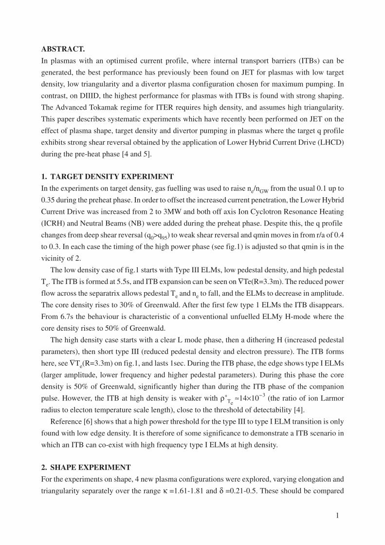
The low density case of fig.1 starts with Type III ELMs, low pedestal density, and high pedestal
Te. The ITB is formed at 5.5s, and ITB expansion can be seen on ∇Te(R=3.3m). The reduced power
flow across the separatrix allows pedestal Te and ne to fall, and the ELMs to decrease in amplitude.
The core density rises to 30% of Greenwald. After the first few type 1 ELMs the ITB disappears.
From 6.7s the behaviour is characteristic of a conventional unfuelled ELMy H-mode where the
core density rises to 50% of Greenwald.
The high density case starts with a clear L mode phase, then a dithering H (increased pedestal
parameters), then short type III (reduced pedestal density and electron pressure). The ITB forms
here, see ∇Te(R=3.3m) on fig.1, and lasts 1sec. During the ITB phase, the edge shows type I ELMs
(larger amplitude, lower frequency and higher pedestal parameters). During this phase the core
density is 50% of Greenwald, significantly higher than during the ITB phase of the companion
pulse. However, the ITB at high density is weaker with ρ*Te ≈14×10-3 (the ratio of ion Larmor
radius to electon temperature scale length), close to the threshold of detectability [4].
Reference [6] shows that a high power threshold for the type III to type I ELM transition is only
found with low edge density. It is therefore of some significance to demonstrate a ITB scenario in
which an ITB can co-exist with high frequency type I ELMs at high density.
2. SHAPE EXPERIMENT
For the experiments on shape, 4 new plasma configurations were explored, varying elongation and
triangularity separately over the range κ =1.61-1.81 and δ =0.21-0.5. These should be compared

2
with κ =1.61and δ =0.21 for the usual JET scenario. The LH preheat scheme was used to generate
a shear reversed target. The companion paper [7] discusses the effect of shape on the core magnetic
topology and the dynamics of ITB formation. This section concentrates on the effect of shaping on
the H mode pedestal.
At low triangularit y, δ < 0.23, the variation in elongation from 1.61 (standard scenario) to 1.67
and 1.76 has negligible effect on the ELMs and H-mode pedestal. The ELMs remain type III,
though there is a reduction in frequency (from 350Hz to 120Hz for 16MW at 2.2MA/2.6Tesla))
with increasing elongation. The electron pedestal pressure remains around 5kPa (similar to the low
density case of fig.1). There is however evidence for an improved core ion temperature suggestive
of a beneficial effect of elongation on the ITB [7].
However, at low elongation (κ =1.62) and higher triangularity (δ = 0.36) the H mode behaviour
is very different as shown in fig.2. In this case, with only 8MW across the separatrix, there is a
transition from type III ELMs to an ELM free phase where the pedestal electron pressure increases
to 10kPa. The temperature drop at the first and subsequent type I elms is sufficiently large as to
generate bursts of type III ELMs. During one such burst, an ITB forms and thereafter the ELMs
remain type III. Note that the pedestal density, temperature and separatrix power are very similar at
the start of the ELM free phase and at the beginning of the long type III phase.
With higher triangularity and elongation (δ =0.5,κ =1.81 similar to proposed ITER values) the
transition from L mode to Type III and thence to Type I and ELM free occurs over a narrow range
of power flow across the separatrix, 4-5MW, as shown in Fig.3. During these ELM free phases the
electron pedestal pressure rises even higher up to 20kPa and in all such cases the first ELM triggered
a Vertical Displacement Event (VDE). In conventional ELMy H-modes with ITER-Like shapes [8]
a similar problem occurs which can be avoided by deuterium gas fuelling. This has not yet been
attempted in this scenario.
3. VARIATION OF DIVERTOR PLASMA GEOMETRY
On the MKIIA divertor it was possible to establish ITB plasmas at high power with either an L-
mode or ELMy edge, for example [8]. It is noteworthy that the MKIIA divertor permitted
configurations with the strike points on the horizontal targets immediately in front of the pump
throats. However, on MKIIGB the threshold for type III ELMs is below the threshold for ITBs [4],
and moreover transitions to type I ELMs can occur if the clearance between divertor plasma channel
and the septum is too small [10]. The septum limits the strike points such that, for the standard
configuration, the diverted scrape off layer is partly in the pump throat and partly on the vertical
target. In the experiment described in this section, the geometry of divertor plasma channels was
varied relative to the divertor targets. Four configurations were compared with the standard geometry;
(1) both strikes on vertical target clear of pump throat, (2) outer strike on horizontal target in front
of pump throat, (3) inner strike on horizontal target in front of pump throat and (4) a configuration
with the outer divertor leg close to the septum. In each case LH preheat and then 16MW of combined

3
heating in the high power phase was employed. In all cases the edge first showed type III ELMs
and then an ITB was formed. During this phase the evolution of pedestal density was nearly identical
(provided the appropriate region on the target was well conditioned), though there were variations
in divertor and main chamber neutral pressure. Variations in electron temperature pedestal were
fairly small <10%. However three of the configurations showed, typically 2sec after the start of the
high power phase, a gradual increase in ELM amplitude and reduction in ELM frequency and
eventually a transition to a type I phase similar to that reported in [10]. This change in behaviour
was not triggered by any heat pulse from the core. During the phase where the type III ELM
amplitude increased the pedestal density, and electron temperature also increased, and continued to
do so between the type I ELMs. It is not at all clear why these configurations are prone to this whilst
the standard configuration and the configuration with the outer strike on the horizontal target were
not. This experiment will be repeated once the septum is removed, and compared with configurations
with both strikes on the horizontal targets in front of the pump throats (as used on MKIIA).
CONCLUSIONS
It is possible to raise the density in ITB scenarios, by gas fuelling in the preheat phase, such as to
permit acceptable ELM behaviour. Increasing the elongation, at low triangularity, increases the
ITB performance whilst also maintaining acceptable ELM behaviour. However increasing the
triangularity at low elongation favours the formation of a strong H-Mode pedestal with long intervals
between Type I ELMs. Fortunately it is still possible to form and sustain an ITB following reverse
type I to type III transitions. At the highest elongation and triangularity, the ELM free pedestal is
even stronger, but it has not proved possible, as yet, to avoid a VDE at the first type I ELM.
ACKNOWLEDGEMENT
This work has been conducted under the European Fusion Development agreement and is
partly funded by Euratom and the UK Department of Trade and Industry.
REFERENCES
[1]. C.Gormezano et al IAEA 2000, Sorrento.
[2]. E.Lazarus et al Phys. Rev. Lett. 77(1996)p2714.
[3]. ITER Joint Central Team 1999 ITER-ODR (Outline Design Report) GA0RI 2 99-12-12 W0.3.
[4]. C. Challis et al, these proceedings.
[5]. J. Mailloux et al, these proceedings.
[6]. M. Bécoulet et al, these proceedings
[7]. O. Tudisco et al, these proceedings.
[8]. Saibene et al, these proceedings.
[9]. M. Keilhacker et al, Nucl Fusion 39, 1999, p209.
[10]. G. Gormezano, 27 th EPS CCFPF, Budapest, ECA 24b(2000) p245.

4
Figure 3: Various time traces for several pulses exploringthe type III to ELM free transition (vertical bars) for ITER-LIKE shape. Pulse No: 52651 (cyan trace) used an argonbleed which restored L mode edge.
2 3 4 5 6 7
VV
eV E
+ 3
Pro
c S
igE
+ 4
Pro
c S
ig Input Power (MW)Neutrons (1e15s-1)
Low Density 51573, High Density 51680 (Red)
Density/Greenwald
Te Gradient at R-3.3m(eV/m)
Pedestol Te (eV)
Pedestol Pressure (PA)
D-alpha 51573
D-alpha 51680
Pro
c S
igE
- 1
Pro
c S
igE
+ 4
Time (s)JG
03.4
26-1
c
0240
10
1123
123
240
1020
Neutrons
Pin
Core
Edge
Dithering H
ITB Expansion
ITB
Type I
Type I
Type III ELMs
1
0
1
20246
123
0
1
3.5 4.0 4.5 5.0 5.5 6.0 6.5
Pro
g S
igE
+4
VeV
E +
3P
rog
Sig
E +
19
*(*)
E +
7
Time (s)
JG03
.426
-2c
Pulse No: 52622 δ = 0.36, κ = 1.62Powers (W)
Pin
Core
PedestollTB
Type III ELMs
Prod
Pin
ProdPsep
Psep
Density (m-3)
Te (eV)VariousRadii
D-alpha(arb)
Pedestol Pressure(Pa)
Figure 2: Various time traces for low elongation fairlyhigh triangularity Pulse No: 52622. Vertical bars marktype III to ELM free transition and also duration of ITB.
Figure 1: Various time traces for low target density 51573and high target density 51680 (red). Both pulses haveplasma current 2.2MA and toroidal field 2.6Tesla
024
0
1
21
2
3024
0
10
1
3 4 5 6 7 8
Pro
c S
igP
roc
Sig
E +
4eV
E +
3P
roc
Sig
E +
19
Pro
c S
igE
+ 7
Pro
c S
igE
+ 7
Time (s)
JG03
.426
-3c
Pulse No's: 52640, 42, 45, 47, 51 δ = 0.5, κ = 1.81 Pin (W)
Psep (W)
Pedestal Density (m-3)
Pedestal Te (eV)
Pedestal Pressure (Pa)
D-alpha (Offset)