the effects of e20 on automotive fuel pumps...
TRANSCRIPT

2/21/2008
1
The Effects of E20 on Automotive Fuel Pumps and Sending Units
Gary Mead, Paul Steevens, Bruce Jones, Nathan Hanson, Thomas Devens, Colin Rohde, Adam Larson
Minnesota Center for Automotive Research At Minnesota State University, Mankato
ABSTRACT
The focus of this study was to compare the effects of E20 versus E10 and gasoline on automotive fuel pumps and sending units in terms of corrosion and longevity. Only electric automotive fuel pumps and sending units were tested. A 30-day static soak test was conducted on eight fuel pumps and three sending units in three different fuels for a total of 24 fuel pumps and 9 sending units. Pre-immersion and post-immersion performance data was measured and compared.
INTRODUCTION
Minnesota Governor Tim Pawlenty signed a bill on May 10, 2005 that requires by volume 20% of the fuel sold in the State of Minnesota to be ethanol. Ethanol is considered a renewable fuel and is also classified as an alternative fuel since it can be used as a substitute for gasoline. Currently, gasoline sold in Minnesota contains 10% ethanol (E10) by volume. The 2005 bill allows for two methods of achieving the 20% goal.
First, if by December 31, 2010 the volume of ethanol sold through the combination of E10 and E85 reaches 20% of the total gasoline sold in the State, then the goal will be met and there will not be any changes in the fuel sold. If the combination of the two fuels’ ethanol content does not reach at least 20% of the total fuel sold, then by August 30, 2013 the ethanol content of gasoline will be increased from 10% to 20% by volume (Eisenthal, 2005).
Before this mandate can be implemented, extensive research must be conducted to ensure compatibility of fuel systems operating on E20 in automobiles, small engines, and marine applications. This paper represents one in a series of four papers that focus on the effects of 20% ethanol-blended fuel (E20) on fuel system components. The experiment consisted of soaking the fuel pumps and sending units, in a static state, for a period of 30 days in gasoline, E10, and E20. This test was derived from SAE Standard J1537, Validation Testing of Electric Fuel Pumps for Gasoline Fuel Injection Systems (SAE, 1990).
TESTING
The E20 fuel pump project is intended to test the effects of a 20% ethanol mixture with gasoline on fuel pumps
and sending units. Gasoline and E10 were included in the study as a reference to see what effects two accepted fuels would have on the pumps and sending units. The inclusion of E10 was significant to this study because ethanol often does cause different changes than gasoline to materials. E10 has been used for over 10 years in all Minnesota gasoline and in many other parts of the United States without causing problems. Therefore, if E20 does not cause any more significant changes than E10, it would be considered acceptable.
FUEL PUMPS
Eight different fuel pumps were selected for this study. Three of each type of fuel pump, one for each test fuel, was used for a total of 24 pumps. Pumps were selected to include a variety of manufacturers, model years, and three common pump designs: rollervane, turbine, and gear rotor. They were also selected to include a broad sample of high volume vehicles on the road today. The fuel pumps tested are listed below.
• Volkswagen Passat 93-94 (Part#1H0919051AL) • Jeep Wrangler 99-00 (Part# 5012952AO) • Ford truck 90-93 (Part# F8PZ9A213AB) • GM TBI truck pump 87-92 (Part# 25168719) • GM PFI early 90's rollervane (Part # 25163468) • GM port pump 00-02 (Part# 25345026) • Toyota Camry LE 02-05 (Part# 232210A030) • Honda Accord 98-02 (Part# 17040S84A02)
SENDING UNITS
Three different manufacturers’ fuel sending units were selected for the testing, one of each type in each test fuel for a total of nine sending units. Fewer sending units were tested than pumps due to the similarity in the silver alloy resistive contact strips. The sending units used in the study are listed below.
• Jeep Wrangler 99-00 (Part# 5012952AO) • GM port pump 00-02 (Part# 25345026) • Honda Accord 98-02 (Part# 17040S84A02)
TEST FUELS
Gasoline composition varies from batch to batch, seasonally, and regionally throughout the United States.

2/21/2008
2
Because of the variation in gasoline composition, three standard reference fuels: C, C(E10)A, and C(E20)A were used for the testing to represent gasoline, E10, and E20, respectively. These fuels were blended specifically for materials testing to represent a worst-case-scenario. The composition of these fuels came from SAE Standard J1681 Gasoline, Alcohol, and Diesel Fuel Surrogates for Materials Testing (SAE, 2000). Using fuels that complied with the standard ensured accurate and consistent results because the fuel is blended out of three main components: iso-octane, toluene, and synthetic ethanol. The iso-octane is used to represent the paraffins, and the toluene is used to represent the aromatic portion of gasoline. Synthetic ethanol is used because of its purity and lack of water. This allows impurities such as water, acids, and salt to be added in specific quantities to turn synthetic ethanol into aggressive ethanol. Aggressive ethanol is a worst-case -scenario fuel that would still be acceptable under ASTM D4806 Standard specification for denatured fuel ethanol for blending with gasoline for use as automotive spark-ignition engine fuel (ASTM, 2006). All components were weighed and splash blended to ensure fuel composition accuracy. The compositions of three test fuels used are listed below.
Surrogate gasoline [C] - ASTM Fuel C, 50/50 toluene iso-octane mixture (500 ml toluene and 500 ml iso-octane)
E10 fuel [C(E10)A] - 90% Fuel C + 10% aggressive ethanol (450 ml toluene, 450 ml iso-octane, 100 ml aggressive ethanol)
E20 fuel [C(E20)A] - 80% Fuel C + 20% aggressive ethanol (400 ml toluene, 400 ml iso-octane, 200 ml aggressive ethanol)
Aggressive ethanol consists of synthetic ethanol 816.00 g, de-ionized water 8.103 g, sodium chloride 0.004 g, sulfuric acid 0.021 g, and glacial acetic acid 0.061 g (SAE J1681 Appendix E.1.2)
TEST FIXTURE AND DATA ACQUISITION
A fixture to operate and measure the pumps was built using the specifications called out in SAE J1537. The fixture has an adjustable flow control valve to allow the pressure to be regulated. It also has a variable power supply to allow the pumps to be tested from 6 to 18 volts. See Appendix 1 for a detailed diagram of the test fixture. The fixture also allowed voltage, amperage, flow, and pressure to be measured and recorded. National Instruments NI USB-6009 was used for the data acquisition and National Instruments LabVIEW software was used to view and record the data. See Appendix 2 for the measurement instrumentation used and pictures of the test fixture.
FUEL PUMP SOAK TEST
The static fuel pump soak test was designed to simulate the effects of a fuel on components when a vehicle is left sitting for 30 days. This test was performed to address problems such as corrosion on armatures or pumping mechanisms, corrosion of electrical terminals, and swelling of internal components such as turbines or housings. Problems such as these could lead to reduced pump output, reduced pump life, hard starting, or no start conditions. The procedure for the static soak test was derived from SAE standard J1537 and was peer reviewed by a group of fuel system experts. The full test procedure used is available in Appendix 3.
PUMP TEST PROCEDURE
Each fuel pump underwent a break-in period before any measurements were recorded. This consisted of running the pumps for 30 minutes at 13.5 volts with the output pressure held at the manufacturer’s recommended specification for the pump’s application. Stoddard solvent (MIL-C-7024B) was used during the break-in period. After the break-in period, all of the pumps were photographed.
Next, the performance of each fuel pump was measured from 6 to 18 volts in 2 volt increments. Again, pressure was held at the manufacturer’s recommended specification for the pump’s application and the current and flow were measured.
Finally, the fuel pumps were operated in the specific fuel [C(E10A), C(E20A), or ASTM Fuel C] to flush out the Stoddard solvent and to prime the pumps. Once the pumps were primed in the specific fuel, they were sealed into their own individual container for a length of 30 days at a temperature of 20 ± 10 ˚C.
After the 30-day soak period, the pumps were photographed and visually inspected for any corrosion or material degradation. Each fuel pump was installed into the test fixture and tested at 10 volts. To pass the test, the fuel pump needed to start unassisted using 10 volts and meet or exceed its pre-immersion flow within 5 minutes (SAE J1537). After the 10-volt start-up test, each pump was again measured in the same manner as pre-immersion.
SENDING UNIT SOAK TEST
The static sending unit soak test was designed to simulate the effects of a fuel when a vehicle is left sitting for 30 days. This test was performed to address problems such as corrosion, build up, or degradation of the sending unit wiper and resistive material. Problems such as these could lead to improper fuel gage readings, which could cause a vehicle to run out of fuel and/or interfere with other functions on the vehicle that rely on the fuel level such as canister purging or evaporative

2/21/2008
3
system checks. Standardized sending unit test procedures could not be located so the procedures used for the testing were developed from SAE standard J1537 and peer reviewed by a group of fuel system experts. The sending units were subjected to a 30-day soak test. The voltage sweep of each one was measured both wet and dry, before and after immersion, to check for resistance changes and signal dropout. See Appendix 4 for complete sending unit soak test procedures.
SENDING UNIT SOAK PROCEDURE
First, each sending unit underwent a break-in period before any measurements were recorded. This consisted of submerging the sending unit in Stoddard solvent (MIL-C-7024B) and cycling the wiper arm 50 full-range sweeps with 5 volts applied to the sending unit. After the break-in, the sending units were measured both dry and wet (in the test fluid that the unit was going to be soaked in) by moving the wiper arm through its full range of motion while recording the voltage change and checking for signal dropout. After all the sending units were measured, they were placed into HDPE containers filled with the appropriate test fluid and sealed. Next, they were allowed to soak for 30 days at a temperature of 20 ± 10 ˚C.
After the completion of the soak period, the sending units were removed and measured in the same manner as they were pre-immersion. The sending units were visually inspected for corrosion or degradation and photographed. For E20 to be considered compatible, the sending unit could not exhibit any more significant changes in resistance than it did with Fuel C or E10. Also, any signal dropout in the sweep was considered unacceptable.
RESULTS
FUEL PUMP SOAK RESULTS
The fuel pumps were inspected visually and photographed pre- and post-immersion for discoloration, corrosion, and swelling. The test fuel was also inspected and photographed for discoloration and loose by-products. Fluid discoloration was most evident among the Ford truck fuel pumps (90-93) and the Jeep Wrangler fuel pumps (99-00). All three fuels that the Ford truck pumps were soaked in showed equal amounts of fluid discoloration. The fuels that the Jeep Wrangler pumps were soaked in also showed discoloration, but it was much more evident as the ethanol concentration increased (see Figure 1). None of the pumps themselves were found to be discolored. Also, no loose by-products were in any of the containers. The o-rings around the body of the Volkswagen fuel pumps swelled considerably and became loose enough that they could be easily removed in all three test fuels. The GM TBI fuel pumps subjected to E10 and E20 showed darkening of the electrical terminals.
Figure 1. Jeep Wrangler Fuel Pumps (left E20 pre-immersion; right E20 post immersion)
Performance data on pressure, flow, and current was collected before and after the soak test. According to SAE J1537, the fuel pump must start unassisted after immersion using 10 volts and meet or exceed its pre-immersion flow within 5 minutes. All of the fuel pumps tested in each of the three fuels met the validation criteria listed in SAE J1537.
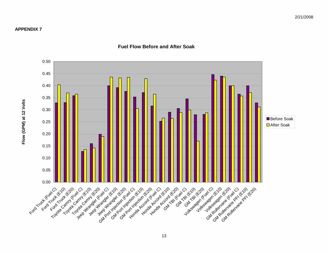
The pre-immersion and post-immersion flow data for each of the pumps was compared. See Appendix 5 for a complete list of pump data at 12 volts and Appendix 7 for a graph comparing the fuel flow at 12 volts. In terms of flow, trends were very similar among pumps of the same make and model in each of the three fuels, with one exception, the GM TBI pump soaked in E10. This pump experienced a 40% drop in flow, where all of the other pumps experienced increases or decreases of only 20% in any of the three fuels. This was the only pump that experienced a large drop in flow in any of the fuels.
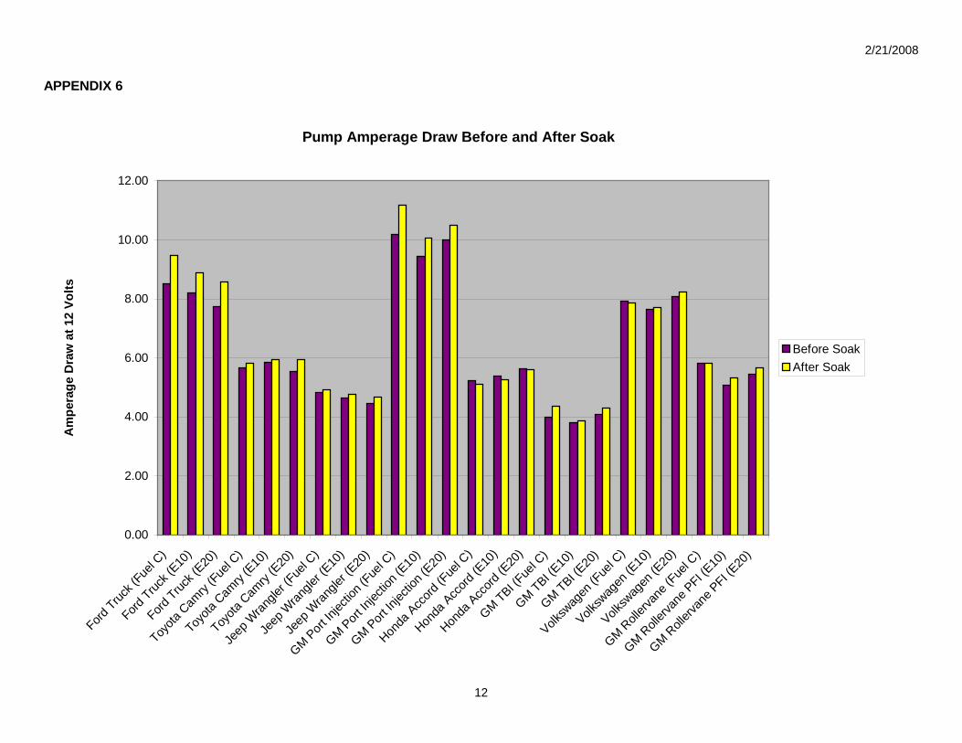
In terms of current draw, trends were very similar among pumps of the same make and model in each of the three fuels. None of the pumps experienced a large increase or decrease in current draw from any of the three test fuels. See Appendix 5 for a complete list of pump data at 12 volts and Appendix 6 for a graph comparing the current draws at 12 volts.
SENDING UNIT RESULTS
The sending units were inspected visually and photographed before and after the immersion period for discoloration, corrosion, and swelling. The test fuel was also inspected and photographed for discoloration and loose by-products. Neither the sending units nor test fluids experienced any discoloration throughout the study. Also, none of the sending units experienced any

2/21/2008
4
visual corrosion and no loose by-products were found in the test fuels.
Next, the voltage change of each sending unit, while being supplied 5 volts, was compared from full to empty. Trends were very similar among the same make and model sending units in all three fuels. None of the sending units underwent any significant changes in resistance in any of the fuels. Finally, none of the sending exhibited any signal dropout during the testing.
CONCLUSIONS
This study tested and compared the effects of E20 to that of E10 and gasoline (Fuel C) on eight fuel pumps and three sending units in three different fuels for a total of 24 fuel pumps and 9 sending units. The pumps and sending units were soaked in a static state for 30 days. All of the fuel pumps passed the validation criteria outlined in SAE J1537 in all three fuels. Only one fuel pump, the GM TBI soaked in E10, experienced a significantly different flow change from the beginning of the study to the end. None of the sending units experienced any significant changes in resistance throughout the study. Overall, E20 was found to have a similar effect as E10 and gasoline on fuel pumps and sending units.
ACKNOWLEDGEMENTS
This study would not have been possible without the support and recommendations from a number of individuals, organizations, and companies including:
Briggs & Stratton Delphi Detroit Testing Laboratory, Inc. Ford Motor Company General Motors Intertek Automotive Jewitt and Associates Kohler Minnesota Corn Research and Promotion Council Minnesota Department of Agriculture Renewable Fuels Association S&S Cycle TI Automotive Toro Toyota Zen Fuel LLC / Michael Harrigan
REFERENCES
ASTM International. (2006). Standard specification for denatured fuel ethanol for blending with gasoline for use as automotive spark-ignition engine fuel (ASTM D4806). West Conshohocken, PA: ASTM International.
Eisenthal, J. (2005, May). E20 “Bill finally reaches Gov. Pawlenty’s desk”. Minnesota Ag Connection. Retrieved October 22, 2005, from http://www.minnesotaagconnection.com/story-state.cfm?Id=405&yr=2005
SAE J1681 (Jan2000) Gasoline, Alcohol, and Diesel Fuel Surrogates for Materials Testing. Warrendale, PA.
SAE J1537 (Jun90) Validation Testing of Electric Fuel Pumps for Gasoline Fuel Injection Systems. Warrendale, PA.
TERMINOLOGY
E10 - Fuel consisting of 90% gasoline and 10% ethanol
E20 -Fuel consisting of 80% gasoline and 20% ethanol
Stoddard Solvent (MIL-C-7024B) - A standard reference fluid used for flowing pumps. It is similar to mineral spirits. ASTM Test Fuel C - This is a SAE defined test fuel used to represent a worst-case-scenario gasoline. Test Fuel C is composed of 50% toluene and 50% iso-octane.
Aggressive Ethanol - A fuel used for material testing that is designed to be a worst-case-scenario fuel that is still acceptable under ASTM D4806. It consists of synthetic ethanol 816.00 g, de-ionized water 8.103 g, sodium chloride 0.004 g, sulfuric acid 0.021 g, and glacial acetic acid 0.061 g.
C(E10)A - Fuel consisting of 90% ASTM Fuel C and 10% aggressive ethanol
C(E20)A - Fuel consisting of 80% ASTM Fuel C and 20% aggressive ethanol
CONTACT
Department of Automotive Engineering Technology Minnesota State University, Mankato 205 Trafton Science Center East Mankato MN, 56001 Phone: (507)-389-6383

2/21/2008
5
APPENDIX 1
TEST FIXTURE DIAGRAM

2/21/2008
6
APPENDIX 2
PART NUMBERS OF MAJOR COMPONENTS
Data Acquisition National Instruments model NI USB-6009 Flow metering Flow meter: Omega model FTB-90507 Signal converter: Omega model FLSC-64
Pressure control Flow Valve: Deltrol fluid products model EF25SS
Pressure Transducer American Sensor Technologies AST4100A00100P1B0103
Power Supply Pumps powered by: Hewlett Packard 6553A Instruments powered by: Delta Electronics model DPS-200PB-125A
Minnesota State University’s Test Fixture Minnesota State University’s Test Fixture side view
Instrument Power supply National Instruments NI USB-6009

2/21/2008
7
APPENDIX 3
This document is intended to outline fuel pump material compatibility testing procedure that was used by the Minnesota Center for Automotive Research (MnCAR). The effects of soaking fuel pumps in E20 were compared to gasoline and E10 in terms of performance (flow and current draw), material degradation, and corrosion. The fuel pumps were subject to a 30-day static soak test in each of the test fuels using the procedure outlined in SAE J1537.
Test Standards Testing followed the procedures outlined in SAE J1537 and J1681 for testing of the fuel pumps. SAE J1537 (Jun90) Validation testing of electric fuel pumps for gasoline fuel injection systems.
SAE J1681 (Jan00) Gasoline, alcohol and diesel fuel surrogates for materials testing.
Test Fuels Three test fuels used consisting of • Surrogate gasoline [C]- "base” ASTM Fuel C 50/50 toluene iso-octane mixture (500 ml toluene and 500 ml iso-
octane) • E10 fuel [C(E10)A]- 90% Fuel C + 10% aggressive ethanol (450 ml toluene, 450 ml iso-octane, 100 ml aggressive
ethanol) • E20 fuel [C(E20)A]- 80% Fuel C + 20% aggressive ethanol (400 ml toluene, 400 ml iso-octane, 200 ml aggressive
ethanol) Aggressive ethanol consists of synthetic ethanol 816.00 g, de-ionized water 8.103 g, sodium chloride 0.004 g, sulfuric acid 0.021g, and glacial acetic acid 0.061g (SAE J1681 Appendix E.1.2) Required Materials
A. three of the same fuel pumps, one for each test fluid B. one liter of test fuel per pump (SAE J1537, 4.3.1) C. variable DC power supply to operate the pumps D. sealable glass containers with PTFE lid seals to hold pumps while submerged in test fuels E. test fixture to measure the flow, pressure, voltage, and current draw of the pumps F. fluid for testing flow: MIL-C-7024B (Type II) Laboratory test fluid (SAE J1537, 3.1.10)
Test Preparation
1. Break in new pumps by operating them at the manufacturer’s recommended pressure for 30 minutes while running in Stoddard solvent (Mil-C-7024B) prior to measuring each pump (SAE J1537, 3.2.3).
2. Measure the pump at voltages ranging from 6 to 18 volts DC in 2 volt increments. Pump pressure will be set and maintained at the manufacturer’s specification as per the pump application. Pump flow and current draw will be measured at each increment (SAE J1537, 4.3.2).
3. Run the pumps in their designated test fluids for a minimum of 30 seconds to clean out the Stoddard solvent from the pump.

2/21/2008
8
4. Clean the test container to be used for the soak test thoroughly; making sure it is free of any contaminants. 5. Mount the pumps into the test containers. Each pump will receive its own container.
Testing 1. Fill the container with a minimum of 1 L of test fluid to completely submerge the pump. 2. Hook the fuel pumps up to the power supply. 3. Run the pumps for approximately 10 seconds to fill them with fluid (SAE J1537, 4.3.1). 4. Seal the container (SAE J1537, 4.3.1). 5. Allow the container to sit sealed for a period of 30 days at a temperature of 20 ± 10 °C (SAE J1537, 4.3.1).
Validation 1. After the soak period, remove the pump from the test fluid. 2. Photograph each pump and note any corrosion or material degradation. 3. Place the pump into the test fixture. 4. Hook the pump up to a 10 volt power supply. The pump must start unassisted (SAE J1537, 4.3.2). 5. Pumps must meet or exceed its rated flow within 5 minutes of operation (SAE J1537, 4.3.2). 6. Re-measure the pump at voltages ranging from 6 to 18 volts DC in 2 volt increments. Pump pressure will be set
and maintained at the manufacturer’s specification as per the pump application. Pump flow and current draw will be measured at each increment (SAE J1537, 4.3.2).

2/21/2008
9
APPENDIX 4
This document is intended to outline fuel sending unit compatibility testing procedures used by the Minnesota Center for Automotive Research (MnCAR). The effects of E20 as compared to gasoline and E10 on the performance of automotive fuel sending unit components were tested. The sending units were subjected to a 30-day static soak test in each of the test fuels. The sending units’ resistance and operation were measured before and after the soak test.
Test Standards No standardized testing procedures for fuel level sending units could be located. Because of this, procedures were developed using some of the recommendations contained in SAE J1537. SAE J1537 (Jun90) Validation testing of electric fuel pumps for gasoline fuel injection systems.
SAE J1681 (Jan00) Gasoline alcohol and diesel fuel surrogates for materials testing.
Test Fuels Three test fuels used consisting of • Surrogate gasoline [C]- "base” ASTM Fuel C 50/50 toluene iso-octane mixture (500 ml toluene and 500 ml iso-
octane) • E10 fuel [C(E10)A]- 90% Fuel C + 10% aggressive ethanol (450 ml toluene, 450 ml iso-octane, 100 ml aggressive
ethanol) • E20 fuel [C(E20)A]- 80% Fuel C + 20% aggressive ethanol (400 ml toluene, 400 ml iso-octane, 200 ml aggressive
ethanol) Aggressive ethanol consists of synthetic ethanol 816.00 g, de-ionized water 8.103 g, sodium chloride 0.004 g, sulfuric acid 0.021 g, and glacial acetic acid 0.061 g (SAE J1681 Appendix E.1.2) Required Materials
A. three of the same sending unit, one for each test fluid B. 0.5 liters of test fluid per sending unit C. variable dc power supply D. sealable container made of high density polyethylene (HDPE) to hold sending units while submerged in test fuels E. National Instruments model NI USB-6009 to measure the resistance changes
Test Preparation
1. Break in all new sending units by cycling the test arm 50 times across the contacts from the full to empty positions with either 5 volt or 12 volts (depending on the manufacturer’s specifications) while in Stoddard solvent.
2. After the break-in period, rinse the sending units in their designated test fluid. 3. Measured the voltage change through a full sweep of the sending units with the correct voltage applied both wet
and dry. Record the data using National Instruments NI USB-6009 while watching for any signal dropout. 4. Thoroughly clean the test container to be used for the soak test.

2/21/2008
10
5. Mount each sending unit into a separate container.
Testing 1. Fill the container with a minimum of 0.5 L of the test fluid to completely submerge the sending unit assembly. 2. Seal the container. 3. Allow the container to sit sealed for a period of 30 days at a temperature of 20 ± 10 °C
Validation 1. Removed the sending units from the test fluid. 2. Test the sending units, both wet and dry, for voltage change (at top, bottom, and for voltage dropout through a full
sweep) using National Instruments model NI USB-6009. 3. Compare these values with the values recorded before beginning test. 4. Photograph all components to document any visual signs of corrosion.

2/21/2008
11
APPENDIX 5
Pre-Immersion Fuel Pump Data Post Immersion Fuel Pump Data Pump Test Fuel Vehicle Identification Voltage Pressure PSI Flow GPM Amp Voltage Pressure PSI Flow GPM Amp 1A C Ford Truck Pump (90-93) 12.10 42.72 0.33 8.52 12.00 42.82 0.40 9.47 2B C(E10)A Ford Truck Pump (90-93) 12.03 43.50 0.33 8.20 12.01 42.31 0.37 8.88 3C C(E20)A Ford Truck Pump (90-93) 11.99 43.42 0.36 7.72 12.01 43.01 0.37 8.58 4A C Toyota Camry 92-94 12.01 50.81 0.13 5.65 11.99 43.90 0.14 5.81 5B C(E10)A Toyota Camry 92-94 12.01 49.45 0.16 5.83 12.00 43.14 0.14 5.93 6C C(E20)A Toyota Camry 92-94 12.01 50.52 0.20 5.54 12.00 43.30 0.19 5.95 7A C Jeep Wrangler (99-00) 12.02 52.81 0.40 4.82 12.00 50.98 0.44 4.93 8B C(E10)A Jeep Wrangler (99-00) 12.01 53.08 0.39 4.64 12.02 51.38 0.43 4.75 9C C(E20)A Jeep Wrangler (99-00) 12.01 52.28 0.38 4.45 12.01 51.05 0.43 4.68 10A C GM Port Injection (99-02) 12.04 57.31 0.35 10.18 12.00 57.02 0.31 11.16 11B C(E10)A GM Port Injection (99-02) 12.03 57.49 0.37 9.44 12.00 55.85 0.43 10.06 12C C(E20)A GM Port Injection (99-02) 12.08 56.86 0.32 9.99 12.00 56.98 0.37 10.48 13A C Honda Accord Sedan (03-06) 12.01 49.13 0.25 5.23 11.94 47.87 0.27 5.10 14B C(E10)A Honda Accord Sedan (03-06) 12.02 49.62 0.29 5.38 11.97 49.41 0.26 5.25 15C C(E20)A Honda Accord Sedan (03-06) 12.00 49.61 0.31 5.64 12.00 50.29 0.29 5.59 16A C GM TBI Pumps (87-92) 12.01 10.52 0.35 4.00 12.01 11.40 0.30 4.36 17B C(E10)A GM TBI Pumps (87-92) 12.02 10.27 0.28 3.82 12.00 10.58 0.17 3.85 18C C(E20)A GM TBI Pumps (87-92) 12.02 10.67 0.28 4.07 12.00 11.09 0.29 4.29 19A C Volkswagen (93-94) 12.01 54.05 0.45 7.93 12.01 54.92 0.42 7.87 20B C(E10)A Volkswagen (93-94) 12.01 53.56 0.44 7.65 12.04 54.99 0.44 7.72 21C C(E20)A Volkswagen (93-94) 12.00 54.17 0.40 8.06 11.99 54.05 0.40 8.24 22A C GM Rollervane PFI (90-92) 12.01 43.57 0.37 5.82 12.08 43.28 0.36 5.81 23B C(E10)A GM Rollervane PFI (90-92) 12.00 43.32 0.40 5.07 12.01 44.56 0.37 5.31 24C C(E20)A GM Rollervane PFI (90-92) 12.01 43.56 0.33 5.45 12.03 43.21 0.31 5.67
2/21/2008
12
APPENDIX 6
Pump Amperage Draw Before and After Soak
0.00
2.00
4.00
6.00
8.00
10.00
12.00
Ford Truc
k (Fue
l C)
Ford Truc
k (E10
)
Ford Truc
k (E20
)
Toyota
Cam
ry (Fue
l C)
Toyota
Cam
ry (E
10)
Toyota
Cam
ry (E
20)
Jeep
Wran
gler (
Fuel C
)
Jeep
Wran
gler (
E10)
Jeep
Wran
gler (
E20)
GM Port In
jectio
n (Fue
l C)
GM Port In
jectio
n (E10
)
GM Port In
jectio
n (E20
)
Honda
Acc
ord (F
uel C
)
Honda
Acc
ord (E
10)
Honda
Acc
ord (E
20)
GM TBI (Fue
l C)
GM TBI (E10
)
GM TBI (E20
)
Volksw
agen
(Fue
l C)
Volksw
agen
(E10
)
Volksw
agen
(E20
)
GM Roll
ervan
e (Fue
l C)
GM Roll
ervan
e PFI (E
10)
GM Roll
ervan
e PFI (E
20)
Am
pera
ge D
raw
at 1
2 Vo
lts
Before SoakAfter Soak
2/21/2008
13
APPENDIX 7
Fuel Flow Before and After Soak
0.00
0.05
0.10
0.15
0.20
0.25
0.30
0.35
0.40
0.45
0.50
Ford Truc
k (Fue
l C)
Ford Truc
k (E10
)
Ford Truc
k (E20
)
Toyota
Cam
ry (Fue
l C)
Toyota
Cam
ry (E
10)
Toyota
Cam
ry (E
20)
Jeep
Wran
gler (
Fuel C
)
Jeep
Wran
gler (
E10)
Jeep
Wran
gler (
E20)
GM Port In
jectio
n (Fue
l C)
GM Port In
jectio
n (E10
)
GM Port In
jectio
n (E20
)
Honda
Acc
ord (F
uel C
)
Honda
Acc
ord (E
10)
Honda
Acc
ord (E
20)
GM TBI (Fue
l C)
GM TBI (E10
)
GM TBI (E20
)
Volksw
agen
(Fue
l C)
Volksw
agen
(E10
)
Volksw
agen
(E20
)
GM Roll
ervan
e (Fue
l C)
GM Roll
ervan
e PFI (E
10)
GM Roll
ervan
e PFI (E
20)
Flow
(GPM
) at 1
2 Vo
lts
Before SoakAfter Soak