the effects of cycling on heat pump performance - gov.uk · pdf fileea technology limited,...
TRANSCRIPT
CONFIDENTIAL REPORT
Prepared for:
Department of Energy and Climate Change (DECC)
The Effects of Cycling on Heat Pump Performance
Author: Robert Green
P ro j ec t No : 466 40
November 2012
CONFIDENTIAL - This document may not be disclosed to any person other than the addressee or any duly authorised person within the addressee's company or organisation and may only be disclosed so far as is strictly necessary for the proper purposes of the addressee which may be limited by contract. Any person to whom the document or any part of it is disclosed must comply with this notice. A failure to comply with it may result in loss or damage to EATL or to others with whom it may have contracted and the addressee will be held fully liable therefor. Care has been taken in the preparation of this Report, but all advice, analysis, calculations, information, forecasts and recommendations are supplied for the assistance of the relevant client and are not to be relied on as authoritative or as in substitution for the exercise of judgement by that client or any other reader. EA Technology Ltd. nor any of its personnel engaged in the preparation of this Report shall have any liability whatsoever for any direct or consequential loss arising from use of this Report or its contents and give no warranty or representation (express or implied) as to the quality or fitness for the purpose of any process, material, product or system referred to in the report. All rights reserved. No part of this publication may be reproduced or transmitted in any form or by any means electronic, mechanical, photocopied, recorded or otherwise, or stored in any retrieval system of any nature without the written permission of the copyright holder. © EA Technology Ltd November 2012
EA Technology Limited, Capenhurst Technology Park, Capenhurst, Chester, CH1 6ES; Tel: 0151 339 4181 Fax: 0151 347 2404 http://www.eatechnology.com
Registered in England number 2566313
Project No: 46640
The Effects of Cycling on Heat Pump Performance

EA Technology The Effects of Cycling on Heat Pump Performance Project No. 46640
The Effects of Cycling on Heat Pump Performance by Robert Green
Summary Standard radiator systems are often used to distribute heat within properties heated by heat pumps. It is good practice, in such cases, to use Thermostatic Radiator Valves (TRVs) to control the heat output from individual radiators. However, their use will increase the tendency for the heat pump to cycle on and off. The work presented in this report was undertaken to explore the effects on the energy performance of heat pumps when short heat pump run times are induced by TRVs closing. The tests were conducted in one of the Test Houses at EA Technology using both an air source and a ground source heat pump. Both heat pumps use single, fixed speed, compressors. The results show that short cycling (run times of less than 6 minutes) have a detrimental effect on the energy performance of both types of heat pump, although the effect is much greater for air source than for ground source. Results are also reported for tests that included a small buffer tank within the heating system. Generally energy performance was improved under conditions that without the buffer tank would have resulted in impaired performance. It is recommended that systems be designed to achieve a minimum run time of circa 6 minutes under all conditions, to avoid the worst excesses of performance impairment due to short cycling. Longer run times are likely to give additional benefits. Methods of achieving these minimum run times, both with and without a buffer tank, are discussed.

EA Technology The Effects of Cycling on Heat Pump Performance Project No. 46640
Contents
Page
1 Introduction 1
1.1 Background 1 1.2 Aims of 2012 tests 1 1.3 Test House 2 1.4 Test methodology 2 1.5 Report Outline 3
2 Air Source Heat Pump 3
2.1 ASHP nominal duty 3 2.2 Test procedure 3 2.3 Detailed results 4 2.4 Summary of Results 5
2.4.1 Current trial 5 2.4.2 Results compared to the previous (2011) trial 6 2.4.3 Room thermostat cycling 7
3 Ground Source Heat Pump 8
3.1 System preparation 8 3.2 GSHP nominal duty 9 3.3 Test procedure 9 3.4 Detailed results 10
3.4.1 Continuous run 10 3.4.2 Forced Cycling 11
3.5 Summary of results 12 3.5.1 Initial results 12 3.5.2 Additional results 12 3.5.3 Run time and ground temperatures 13 3.5.4 Comparison with manufacturer’s data 14 3.5.5 Room thermostat operation 15
4 Buffer tank set-up 16
4.1 Plumbing and control 16 4.2 Buffer tank design method 17 4.3 Central heating pump selection 17
5 GSHP & Buffer tank 18
5.1 Forced cycling results 18 5.2 Normal operation 19
6 ASHP & buffer tank results 21
6.1 Forced cycling results 21 6.2 Normal operation 22
7 Discussion and Conclusions 24
8 Recommendations 25

EA Technology The Effects of Cycling on Heat Pump Performance Project No. 46640
Appendix 1 ASHP – detailed results 26
A1.1 Long Runs 26 A1.1.1 Low ambient with defrost 26 A1.1.2 5oC ambient – no defrost 27 A1.1.3 Mild day (12oC) 28
A1.2 Short cycling – 1 radiator 29 A1.2.1 Near zero (0oC) – no defrost 29 A1.2.2 6oC - no defrost 30 A1.2.3 Mild day (12oC) 31
A1.3 Short cycling – 2 radiators 32 A1.3.1 Near zero (0oC) – some defrost 32 A1.3.2 7oC - no defrost 33 A1.3.3 Mild day (12oC) 34
A1.4 ASHP results – thermostat cycling 35 A1.4.1 Lounge and dining room 35
Appendix 2 GSHP – detailed results 36
A2.1 Continuous 36 A2.2 7 radiators open 37 A2.3 5 Radiators open 38 A2.4 4 Radiators open 39 A2.5 3 Radiators open 40 A2.6 2 Radiators open 41 A2.7 1 Radiator open 42 A2.8 GSHP results – thermostat cycling 43
A2.8.1 Lounge and dining room 43 A2.8.2 Hall 44
Appendix 3 GSHP & buffer tank 46
A3.1 Hall radiator open 46 A3.2 Lounge and dining room radiators open 47 A3.3 Normal operation 49
Appendix 4 ASHP & buffer tank 50
A4.1 Hall radiator open 50 A4.2 Lounge and dining room radiators open 51

EA Technology The Effects of Cycling on Heat Pump Performance Project No. 46640
Glossary ASHP Air Source Heat Pump
CH Central Heating
COP Coefficient of Performance of a heat pump
(heat energy output divided by electric energy input)
DECC Department of Energy and Climate Change
DHW Domestic Hot Water
EST Energy Saving Trust
GSHP Ground Source Heat Pump
TRV Thermostatic Radiator Valve

EA Technology The Effects of Cycling on Heat Pump Performance Project No. 46640
1
1 Introduction
1.1 Background
Standard radiator systems are often used to distribute heat within properties heated by heat pumps. It is good practice, in such cases, to use Thermostatic Radiator Valves (TRVs) to control the heat output from individual radiators. However, their use will increase the tendency for the heat pump to cycle on and off. Often TRVs are used in every room except one (usually the lounge or the hall) which contains the room thermostat. As each room reaches its desired temperature, the TRV closes down, reducing both the capability of the system to reject heat and the volume of water being circulated around the system. In the extreme, all the TRVs will close down, and the Central Heating (CH) circuit will be reduced to a small circuit containing a single radiator. Heat pumps are sized to meet the CH demand on a cold design day. During milder weather, the heat pump will inevitably cycle on and off throughout the CH period – this is particularly so in the case of fixed speed compressors common in many current designs. The effect of TRVs closing down is likely to increase the frequency of cycling by, as described above, reducing both the heat output capacity of the system and the water volume. During the spring of 2011 a series of tests1, using an Air Source Heat Pump (ASHP) installed in an unoccupied house with a standard radiator system, was undertaken by EA Technology as an adjunct to the Energy Saving Trust’s Heat Pump Field Trials. These tests established that very short run times could dramatically impair the performance of the Heat Pump as defined by its Coefficient of Performance (COP) – the ratio of the heat delivered to the electrical energy consumed. However, only a limited range of tests was undertaken. This report describes work undertaken during the first half of 2012 to look at a wider range of conditions and to include the performance of a Ground Source Heat Pump (GSHP) as well as an ASHP. The work was directly funded by DECC.
1.2 Aims of 2012 tests
For the ASHP, the aims of the tests were to extend the results from the 2011 series of tests by:
1. including a wider range of ambient air temperatures; 2. looking at the effect of changing the “reference heating zone” (this is the room in
which the room thermostat is located – the radiator(s) here should not have TRVs); 3. attempting to more closely define a minimum run time than was determined from the
2011 test; and 4. to incorporate a small buffer tank into the system to help reduce the likelihood of very
short run times. It was anticipated that cycling would affect GSHPs less than ASHPs, since cycling allows the ground temperature to recover after each cycle, thus potentially increasing the COP (due to
1 R Green & A Knowles, “The effect of thermostatic radiator valves on heat pump performance”, EA Technology, June 2011, available at: http://www.decc.gov.uk/assets/decc/11/meeting-energy-demand/microgeneration/3531-effect-radiator-valves-heat-pump-perf.pdf
EA Technology The Effects of Cycling on Heat Pump Performance Project No. 46640
2
the higher source temperature). There is, however, very little data to support this argument, hence the inclusion of a GSHP in the test programme. For the GSHP, the aims were to:
1. establish the effect on COP of heat pump run time; 2. look at the effect of changing the “reference heating zone”; and 3. incorporate a small buffer tank into the system to help reduce the likelihood of very
short run times.
Specialist advice on GSHP performance, and, in particular, the effect of the ground loop on performance, was provided by Mimer Energy Ltd. Their findings are provided in a separate, parallel, report.
1.3 Test House
As with the 2011 tests, the tests were undertaken in one of EA Technology’s thermally matched Test Houses. The detached, four bedroom, two storey Test Houses were built to a mid-1990s specification but incorporating higher levels of insulation, air-tightness and ventilation than were required under building regulations of the time. Total fabric (and ventilation) heat loss - 200 W/K Design heat loss - 4.4 kW (at -1oC external and 21oC internal temperature). Further details of the house, and the CH system (including replacement radiators designed for a flow temperature of 50oC) are provided in the 2011 report1, as are details of the data logging systems used.
The Test house has an open plan lounge / dining room with a radiator in each half. There are two logical alternatives for the reference heating zone: the hall and the lounge / dining room.
1.4 Test methodology
The ASHP and GSHP units used in the tests are both fixed speed, scroll compressor, machines. As with the 2011 tests, a series of tests were undertaken to systematically vary the heat rejection capacity of the Central Heating (CH) radiator system, by increasing or decreasing the number of radiators in circuit. For the main series of tests, the room thermostat was set high to always create a demand for CH. The heat pump then cycles off when the return water temperature set-point is reached (both machines used very similar, simple, return water temperature, controls). One change from the 2011 tests was to replace the standard, hard-wired, room thermostat with a radio operated room thermostat. This allowed the reference zone to be readily changed, simply by moving the thermostat to the new reference zone and ensuring that the TRV(s) in that room were fully open. Included in the results are a limited number of tests where the room thermostat temperature was reduced to allow the system to cycle on room temperature rather than the heat pump return temperature. Further details of the methodology for each system (ASHP, GSHP with and without buffer tanks) are included later in the report, under the appropriate section.

EA Technology The Effects of Cycling on Heat Pump Performance Project No. 46640
3
1.5 Report Outline
Summary results are presented for each technology in Sections 2(ASHP), 3 (GSHP), 5 (GSHP and buffer tank) and 6 (ASHP and buffer tank), with Section 4 providing a brief description of the buffer tank set-up. More detailed results for each set of tests are provided in the Appendices. Sections 7 and 8 provide a general discussion of the results and provide conclusions and recommendations.
2 Air Source Heat Pump
2.1 ASHP nominal duty
The ASHP used was the same unit as used in the 2011 tests1. It has a nominal heating capacity of 6kW (at 7oC ambient and 35oC flow temperature). This reduces to approximately 4.8 kW at 0oC ambient with a 45oC flow temperature. Thus, the ASHP is sized in-line with the heat demand of the house, although only marginally so and, arguably, is slightly undersized if an allowance for defrost is included. The ASHP only supplies CH.
2.2 Test procedure
The heat pump was set to switch off at a return temperature of 40oC – giving a maximum flow temperature of ~ 46oC (depending on the heat output and CH water flow rate). Results are analysed in 4 hour blocks where the conditions (ambient temperature and heat pump cycling) are reasonably steady (or give regular cycles). Overnight and weekend runs. Most radiator valves were set fully open (although it proved necessary to close some radiators at the lower ambient conditions to achieve the heat pump return temperature of 40oC). The room thermostat was set high to keep the heat pump running. Data logging was at 1 minute intervals. The aim was to obtain performance data at a wide range of ambient temperatures. These results are grouped together in the discussions below as “long runs” and have compressor run times varying from 40 minutes at the lowest ambient temperature (-4oC) reducing to just over 9 minutes at the highest ambient temperature (12oC). Weekday runs. The capacity of the Central Heating circuit was restricted by having only one or two radiators fully open and hence inducing relatively short compressor run times. The room thermostat was set high to maintain a heat demand throughout. Data logging was at 10 second intervals. The aim was to get performance data under short cycling conditions across a range of ambient temperatures.

EA Technology The Effects of Cycling on Heat Pump Performance Project No. 46640
4
2.3 Detailed results
Figure 2.1 provides an example of the detailed results, showing how cycling affects temperatures, power (both heat output and the corresponding electrical input) and per cycle COP.
0
5
10
15
20
25
30
35
40
45
50
0 0.5 1 1.5 2 2.5 3 3.5 4
time (hours)
tem
per
atu
res
flow
return
ambient
-1000
0
1000
2000
3000
4000
5000
6000
7000
0 0.5
1 1.5
2 2.5
3 3.5
4
time (hours)
po
wer
(av
g W
)
0.0
0.5
1.0
1.5
2.0
2.5
3.0
3.5
4.0
CO
P (
per
cyc
le)
ASHP heat (calculated) COP (cycle)
Figure 2.1: Example power & COP graphs (forced cycling, 1 radiator open)
Similar detailed four-hourly plots of the results for a representative selection of the full range of ASHP tests are provided in Appendix 1. Appendix 1, Section A1.1 shows results for cold days and mild days, for the “long runs” (see Section 2.2 above – “Overnight and weekend runs”); whilst Sections A1.2 and A1.3 show corresponding results for short cycling induced by having only 1 radiator or 2 radiators in circuit.
(o
C)

EA Technology The Effects of Cycling on Heat Pump Performance Project No. 46640
5
2.4 Summary of Results
2.4.1 Current trial
0.0
0.5
1.0
1.5
2.0
2.5
3.0
3.5
-6 -4 -2 0 2 4 6 8 10 12 14
ambient temperature
CO
P
long runs - excluding defrostlong runs - including defrostone radiatortwo radiators
44 3.6
2.7 2.9
2.2
7.1
6.56.6
5.95.3
Figure 2.2: Results from the 2012 ASHP tests
The results from the 2012 set of tests are summarised in Figure 2.2. The numbers included on the graph are the compressor run times in minutes for the respective COP point. The solid line is a linear regression fit for the “long runs” (without defrost – note that when defrost energy is included for the low temperature runs, the COP is significantly reduced). A number of observations can be made.
1. Run times (with a given radiator configuration) increase as the ambient temperature decreases – as expected because of the fall in heat pump heat output.
2. The results from the tests with two radiators in circuit (lounge and dining room – the
lounge / dinning rooms are open plan) show run times from 5 to 7 minutes. The COPs for these runs fall below the “long run” line.
3. Whilst the reduction in COP for two radiators is significant, it is small compared to the
reduction when only one radiator is in circuit. Run times with only one radiator vary between 2 minutes and 4 minutes.
4. The offset from the “long run” line doesn’t appear to reduce as the ambient
temperature falls, as may have been expected, despite the increase in run time.
(oC)

EA Technology The Effects of Cycling on Heat Pump Performance Project No. 46640
6
2.4.2 Results compared to the previous (2011) trial
0.0
0.5
1.0
1.5
2.0
2.5
3.0
3.5
-6 -4 -2 0 2 4 6 8 10 12 14 16
ambient temperature
CO
P
long runs - excluding defrostlong runs - including defrostone radiatortwo radiatorscatalogue data2011(day1)2011(day2)2011 one radiator2011 two radiators2011 three radiators
3
3.5
8.3
Figure 2.3: A comparison of the 2011 and 2012 test results
The 2011 results are included for comparison in Figure 2.3. These comprise two series of quasi steady state results (day1 and day2) in which all of the radiators were open; plus three forced cycling tests (one, two and three radiators available). The 2012 “long run” line is slightly above the 2011 “steady-state” values (2011 day 1 and day 2 points), and approaches the manufacturer’s catalogue data (especially at high ambient temperatures). The single radiator run from the 2011 tests is in reasonable agreement with the 2012 series. However, the 2011 2-radiator result is slightly below the 2012 series. The 2011 results suggest that the ideal minimum run time to achieve little or no reduction in COP is somewhere between 3.5 minutes and 8.3 minutes. The 2012 results suggest that the bulk of the improvement is achieved with run times of around 6 minutes.
(oC)

EA Technology The Effects of Cycling on Heat Pump Performance Project No. 46640
7
2.4.3 Room thermostat cycling
On completion of the forced cycling tests, and whilst work progressed on installing the GSHP, the ASHP was left for a short period of time with the room thermostat reduced to normal levels (21oC). Two radiators were in circuit (lounge and dining room with TRVs fully open) with the room thermostat located in the same area (i.e. the open plan lounge / dining is the reference zone) – all other TRVs were fully closed.
0
5
10
15
20
25
30
35
40
45
50
0 0.5 1 1.5 2 2.5 3 3.5 4
time (hours)
tem
per
atu
res
flow
return
ambient
Figure 2.4: Flow and return temperatures under room thermostat control (2 radiators) There is some cycle to cycle variation in COP (see detailed results in Appendix A1.4.1). The run time is very short (2.9 minutes) but the COP is significantly higher than previous tests with similar run times. This is due to the lower flow / return temperatures that are achieved when the systems cycles off on the room thermostat (rather than the return flow temperature).
(o
C)

EA Technology The Effects of Cycling on Heat Pump Performance Project No. 46640
8
Figure 2.5 includes the thermostat cycling result for comparison with the other 2012 (forced cycling) results.
0.0
0.5
1.0
1.5
2.0
2.5
3.0
3.5
-6 -4 -2 0 2 4 6 8 10 12 14
ambient temperature
CO
P
long runs - excluding defrostlong runs - including defrostone radiatortwo radiatorstwo radiators - t/stat
44 3.6
2.7 2.9
2.2
7.1
6.5 6.6
5.95.3
2.9
Figure 2.5: Results including lounge / dining room thermostat cycling
3 Ground Source Heat Pump
3.1 System preparation
The ground loops at the EA Technology test house were installed some 15 years ago and have not been used since the initial test work was completed in the first year after installation. It therefore seemed prudent to test the current state of the ground loops prior to installation of the GSHP. There are two ground loops – one 60 m deep and the other 80 m deep. Initial tests on the loops simply circulated the existing water / anti freeze mix to confirm that a reasonable flow rate could be achieved (using a standard domestic heating circulator). Having established that adequate flow rates could easily be achieved (values of 11 to 25 lpm were measured depending on pump speed and single loop or parallel loop operation), each loop was tested for its thermal response. The test comprised forming a closed loop for each individual ground loop with an inline electric flow boiler (6kW) and measuring the glycol temperature to and from the ground loops. The results of these tests will be reported elsewhere2, but the ground loop specialists, Mimer Energy, confirmed that the loops were adequate for the work reported here.
2 R Curtis, “Effects of cycling on domestic GSHPs, Supporting analysis to EA Technology, Ground loops – testing” Mimer Energy report No: C207-R1, August 2012
(oC)

EA Technology The Effects of Cycling on Heat Pump Performance Project No. 46640
9
A sample of the glycol was sent away for analysis. This indicated that no bacteria were present and that the pH was normal. Frost protection was down to -6oC. The GSHP manufacturer assisted with installation of the GSHP and undertook final commissioning. They flushed ground loop to remove the old glycol and recharged the system with a 26% concentration of “CoolFlow” antifreeze (frost protection to ~ -15oC).
3.2 GSHP nominal duty
The GSHP chosen has a nominal duty (heat output) of 6 kW – catalogue value of 6.2 kW with an antifreeze inlet temperature of 0oC and a flow temperature of 45oC. The GSHP only supplies CH.
3.3 Test procedure
Both ground loops were used, in parallel operation. The heat pump was set to switch off at a return temperature of 40oC – giving a maximum flow temperature of ~ 46oC. The GSHP gives simpler tests than for ASHP, since ambient air temperature is of little importance (especially for the forced cycling tests). Results are analysed in 4 hour blocks where the conditions (temperature and heat pump cycling) are reasonably steady (or give regular cycles).
EA Technology The Effects of Cycling on Heat Pump Performance Project No. 46640
10
3.4 Detailed results
3.4.1 Continuous run
-10
0
10
20
30
40
50
0 0.5 1 1.5 2 2.5 3 3.5 4
time (hours)
tem
per
atu
res
flow
return
Ground In
Ground out
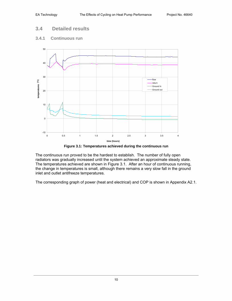
Figure 3.1: Temperatures achieved during the continuous run
The continuous run proved to be the hardest to establish. The number of fully open radiators was gradually increased until the system achieved an approximate steady state. The temperatures achieved are shown in Figure 3.1. After an hour of continuous running, the change in temperatures is small, although there remains a very slow fall in the ground inlet and outlet antifreeze temperatures. The corresponding graph of power (heat and electrical) and COP is shown in Appendix A2.1.
(o
C)

EA Technology The Effects of Cycling on Heat Pump Performance Project No. 46640
11
3.4.2 Forced Cycling
0
5
10
15
20
25
30
35
40
45
50
0 0.5 1 1.5 2 2.5 3 3.5 4
time (hours)
tem
per
atu
res
flow
return
Ground In
Ground out
Figure 3.2: Example temperatures under forced cycling conditions (3 radiators open)
Figure 3.2 shows a typical set of temperature results from the forced cycling tests (in this case, with 3 radiators open). All temperatures cycle regularly and there is little or no variation in maximum or minimum values in any of the measurements. The “ground in” values (i.e. the temperature of the antifreeze returning from the heat pump to the ground) are a surprise in that, when the heat pump cycles off, the temperature overshoots the “ground out” temperature (the expectation would be that the ground-out temperature would always be the higher – or that the two might equalise during the off periods). It is thought that the explanation for this may lie in the temperature changes within the heat pump during its off periods and any small, residual flows in the ground loop after the heat pump has switched off. The tests proceeded by systematically altering the number of fully open radiators in the CH circuit and allowing conditions to stabilise. Detailed results are provided in Appendices A2.2 to A2.7.
(o
C)
EA Technology The Effects of Cycling on Heat Pump Performance Project No. 46640
12
3.5 Summary of results
3.5.1 Initial results
0.0
0.5
1.0
1.5
2.0
2.5
3.0
3.5
0 5 10 15 20 25
run time (minutes)
CO
P (
per
cyc
le)
continuous
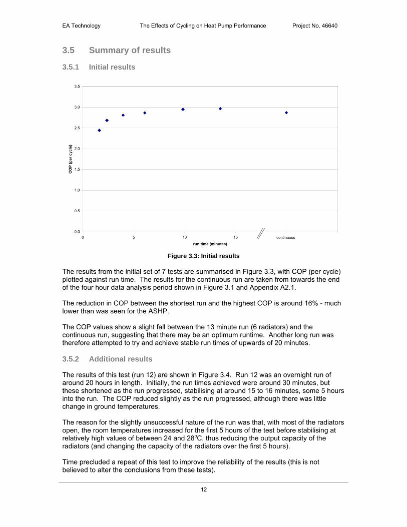
Figure 3.3: Initial results
The results from the initial set of 7 tests are summarised in Figure 3.3, with COP (per cycle) plotted against run time. The results for the continuous run are taken from towards the end of the four hour data analysis period shown in Figure 3.1 and Appendix A2.1. The reduction in COP between the shortest run and the highest COP is around 16% - much lower than was seen for the ASHP. The COP values show a slight fall between the 13 minute run (6 radiators) and the continuous run, suggesting that there may be an optimum runtime. Another long run was therefore attempted to try and achieve stable run times of upwards of 20 minutes. 3.5.2 Additional results
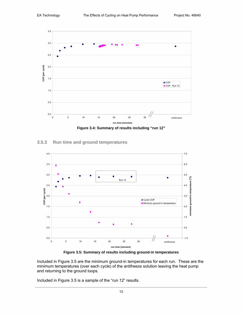
The results of this test (run 12) are shown in Figure 3.4. Run 12 was an overnight run of around 20 hours in length. Initially, the run times achieved were around 30 minutes, but these shortened as the run progressed, stabilising at around 15 to 16 minutes, some 5 hours into the run. The COP reduced slightly as the run progressed, although there was little change in ground temperatures. The reason for the slightly unsuccessful nature of the run was that, with most of the radiators open, the room temperatures increased for the first 5 hours of the test before stabilising at relatively high values of between 24 and 28oC, thus reducing the output capacity of the radiators (and changing the capacity of the radiators over the first 5 hours). Time precluded a repeat of this test to improve the reliability of the results (this is not believed to alter the conclusions from these tests).
EA Technology The Effects of Cycling on Heat Pump Performance Project No. 46640
13
0.0
0.5
1.0
1.5
2.0
2.5
3.0
3.5
0 5 10 15 20 25 30 35 40 45
run time (minutes)
CO
P (
per
cyc
le)
COP
COP - Run 12
continuous
Figure 3.4: Summary of results including “run 12”
3.5.3 Run time and ground temperatures
0.0
0.5
1.0
1.5
2.0
2.5
3.0
3.5
4.0
0 5 10 15 20 25 30 35 40 45
run time (minutes)
CO
P (
per
cyc
le)
-1.0
0.0
1.0
2.0
3.0
4.0
5.0
6.0
7.0
min
imu
m g
rou
nd
-in
tem
per
atu
re (
oC
)
Cycle COP
Minimum ground-in temperature
continuous
Run 12
Figure 3.5: Summary of results including ground-in temperatures
Included in Figure 3.5 are the minimum ground-in temperatures for each run. These are the minimum temperatures (over each cycle) of the antifreeze solution leaving the heat pump and returning to the ground loops. Included in Figure 3.5 is a sample of the “run 12” results.

EA Technology The Effects of Cycling on Heat Pump Performance Project No. 46640
14
3.5.4 Comparison with manufacturer’s data
0.0
0.5
1.0
1.5
2.0
2.5
3.0
3.5
4.0
0 5 10 15 20 25 30 35 40 45
run time (minutes)
CO
P (
per
cyc
le)
-1.0
0.0
1.0
2.0
3.0
4.0
5.0
6.0
7.0
min
imu
m g
rou
nd
-in
tem
per
atu
re (
oC
)
Cycle COP
Ideal COP
Minimum ground-in temperature
continuous
Run 12
Figure 3.6: comparison with manufacturer’s data The results are repeated in Figure 3.6 along with the manufacturer’s steady-state performance estimates for the corresponding flow and ground-in temperatures. (Actually, the manufacturer quotes flow and ground-out temperatures, and only accounts for a proportion of the ground-loop pumping power – thus the manufacturer’s data has been modified to provide a reasonably comparison with the measured data). At the high ground-in temperatures, the very short run times result in substantially lower COPs than the manufacturer’s steady state values. However, achieving these very high ground-in temperatures in all but very short runs is not likely (with practical designs of ground loops). Above about 15 – 20 min, any start up effects is negligible, with a consistent difference between the manufacture’s data and the measured performance.

EA Technology The Effects of Cycling on Heat Pump Performance Project No. 46640
15
3.5.5 Room thermostat operation
During the test period, the system was occasionally left in its “normal” operating state – i.e. room TRVs set to partially open and reference zone room thermostat to a typical comfort temperature (21oC). Figure 3.7 shows one such set of performance temperatures. The run time is a complex function house heat demand as determined by ambient temperature and how many radiator TRVs are not fully closed (i.e. rooms colder than the TRV setpoint). In this case the reference zone is the lounge / dining room and the runtime is only 2.4 minutes. Despite this very short runtime, the cycle COP is 3.2, in excess of the maximum COP (~3.0) achieved in the forced cycling tests. The improvement is due to the lower maximum flow temperatures obtained.
0
5
10
15
20
25
30
35
40
45
50
0 0.5 1 1.5 2 2.5 3 3.5 4
time (hours)
tem
per
atu
res
flow
return
Ground In
Ground out
ambient
Figure 3.7: Full system operation under room thermostat control
More detailed results, including a run with the Hall as the reference zone are provided in Appendix A2.8. The longer run time in the example where the Hall is the reference zone is due to the lower ambient temperature (and hence higher CH demand) during this test. The thermostat cycling results show the highest COPs of all of the GSHP tests.
(o
C)
EA Technology The Effects of Cycling on Heat Pump Performance Project No. 46640
16
4 Buffer tank set-up
4.1 Plumbing and control
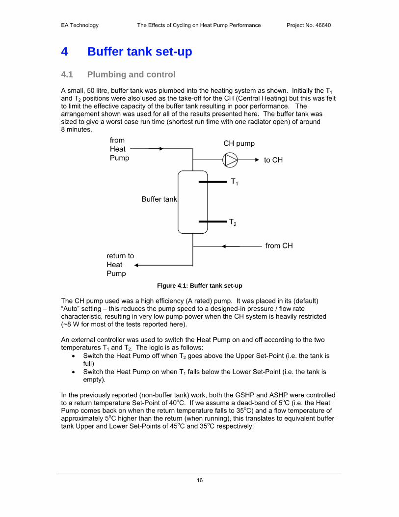
A small, 50 litre, buffer tank was plumbed into the heating system as shown. Initially the T1 and T2 positions were also used as the take-off for the CH (Central Heating) but this was felt to limit the effective capacity of the buffer tank resulting in poor performance. The arrangement shown was used for all of the results presented here. The buffer tank was sized to give a worst case run time (shortest run time with one radiator open) of around 8 minutes.
from HeatPump
return toHeatPump
to CH
from CH
T1
T2
CH pump
Buffer tank
Figure 4.1: Buffer tank set-up
The CH pump used was a high efficiency (A rated) pump. It was placed in its (default) “Auto” setting – this reduces the pump speed to a designed-in pressure / flow rate characteristic, resulting in very low pump power when the CH system is heavily restricted (~8 W for most of the tests reported here). An external controller was used to switch the Heat Pump on and off according to the two temperatures T1 and T2. The logic is as follows:
Switch the Heat Pump off when T2 goes above the Upper Set-Point (i.e. the tank is full)
Switch the Heat Pump on when T1 falls below the Lower Set-Point (i.e. the tank is empty).
In the previously reported (non-buffer tank) work, both the GSHP and ASHP were controlled to a return temperature Set-Point of 40oC. If we assume a dead-band of 5oC (i.e. the Heat Pump comes back on when the return temperature falls to 35oC) and a flow temperature of approximately 5oC higher than the return (when running), this translates to equivalent buffer tank Upper and Lower Set-Points of 45oC and 35oC respectively.

EA Technology The Effects of Cycling on Heat Pump Performance Project No. 46640
17
4.2 Buffer tank design method
As noted above, the buffer tank was sized to give a worst case run time of around 8 minutes. The calculation used is as follows.
QHP = Qrad + Qstored where QHP = heat pump heat output Qrad = radiator heat output Qstored = Heat stored in buffer vessel and heating system
Qstored x trun = (Vopen + Vbuffer) x Cp x ΔT where trun = run time (seconds) Vopen = water volume within open part of CH system (litres) Vbuffer = buffer tank volume (litres) Cp = specific heat capacity of water (4.2 kJ / kg / K) ΔT = temperature range (T2 – T1) Assuming a heat pump duty of 6.7 kW (the ASHP duty at 15oC ambient and 45oC flow temperature); a ΔT of 10K and the worst case scenario of just the hall radiator open (nominal output 0.7 kW and open CH volume of 22 litres); then a 50 litre buffer tank gives a run time of just over 8 minutes. This can only be an approximate calculation, assuming quasi steady-state values (for Qhp and Qrad) in what is a very dynamic, non-steady state, situation. Nevertheless, the test results suggest that the calculation provides a reasonable estimate of runtime / buffer tank volume.
4.3 Central heating pump selection
In addition to ensuring a raised minimum run time, the use of a buffer tank (in the “four-pipe” arrangement used here) has the advantage of decoupling the heat pump (whether GSHP or ASHP) from the CH system. This:
allows the use of a high efficiency speed controlled CH circulating pump to its best advantage (i.e. there is no need to set a minimum flow rate through the CH system that is high enough to ensure adequate flow rate through the heat pump); and
makes commissioning of the system easier. It is important, however, to set the system up so that at maximum heat demand there is a well-matched flow rate from the Heat Pump to the CH system. Failure to match these flow rates will either:
lead to a reduction in heat output capacity of the radiators if the CH flow rate is greater than the Heat Pump flow rate (as the CH flow temperature will be reduced by recycling some of the CH return); or
lead to a reduction in heat pump run time if the Heat Pump flow rate is greater than the CH flow rate (as the Heat Pump return temperature will be increased by the flow from the Heat Pump bypassing the CH).
The particular A rated pump used has an “AUTOadapt” range which was used for most of the buffer tank work. However, it seems that this setting does not give the maximum flow rate when the system is fully open and either a fixed speed setting or a constant pressure setting are more suited to this application.

EA Technology The Effects of Cycling on Heat Pump Performance Project No. 46640
18
5 GSHP & Buffer tank
5.1 Forced cycling results
With the buffer tank in circuit, the CH pattern changes considerably. Figure 5.1 shows the power (heat and electricity) for the case of a forced cycling with a single radiator (the Hall) open. Run times are now around 8 minutes (compared to 1.6 minutes without the buffer tank), and there are fewer cycles per hour. At first sight it would appear that the CH output (the blue / green line) is much reduced compared to the operation without the buffer tank. However, integration of output over time shows that the change is actually quite small.
0
1000
2000
3000
4000
5000
6000
7000
8000
0 0.5 1 1.5 2 2.5 3 3.5 4
time (hours)
po
wer
(av
g W
)
0.0
0.5
1.0
1.5
2.0
2.5
3.0
3.5
4.0
CO
P (
per
cyc
le)
GSHP heat (calculated) CH heat (calculated) COP (cycle)
Figure 5.1: Power (heat and electricity) and COP (forced cycling, 1 radiator) Tests were undertaken for forced cycling with both one (hall) and two (lounge / dining) radiators. Detailed results are provided in Appendix 3. Figure 5.2 compares the buffer tank results with the previous GSHP (no buffer tank) forced cycling results. For the buffer tank results, two COP values are given. An additional heat meter was installed (at the GSHP outlet) when the buffer tank was installed. This new meter gave total heat outputs some 4% lower than those measured by the CH heat meter. The higher COP values (i.e. the values using the CH heat meter) use the same heat meter as was used in the GSHP (no buffer tank) results.

EA Technology The Effects of Cycling on Heat Pump Performance Project No. 46640
19
0.0
0.5
1.0
1.5
2.0
2.5
3.0
3.5
4.0
0 5 10 15 20 25 30 35 40 45
run time (minutes)
CO
P (
per
cyc
le)
Cycle COP
one radiator - (HP meter)
one radiator - (CH meter)
two radiators - (HP meter)
two radiators - (CH meter)
continuous
Figure 5.2: Comparison of GSHP forced cycling results with and without buffer tank
The two points on the original data at the left-most side of the graph are the 1 and 2 radiator values (run times 1.6 and 2.4 minutes respectively). Thus we see a clear advantage for incorporation of the buffer tank, irrespective of which heat meter we place the most faith in. The following table summarises the results (taking the average COP for the buffer tank results).
Table 5.1: Summary of forced cycling results Radiators COP run time
(minutes)maximum
Tflow (oC)
average CH (W)
1 2.44 1.6 48.8 8102 2.68 2.4 48.0 1,910
1 2.77 7.7 46.8 8502 2.99 10.7 46.0 1,800
No buffer
Buffer
5.2 Normal operation
Before moving on to look at the performance of the ASHP with the buffer tank, the system was placed in normal operating mode. In this example the Lounge / Dining room is the reference zone. All other rooms have part open TRVs with typical settings for normal use. The Upper and Lower buffer tank set-points were reduced to 40 and 30oC respectively for these “normal operation” tests.
EA Technology The Effects of Cycling on Heat Pump Performance Project No. 46640
20
0
1000
2000
3000
4000
5000
6000
7000
8000
0 0.5 1 1.5 2 2.5 3 3.5 4
time (hours)
po
wer
(av
g W
)
0.0
0.5
1.0
1.5
2.0
2.5
3.0
3.5
4.0
CO
P (
per
cyc
le)
GSHP heat (calculated) CH heat (calculated) COP (cycle)
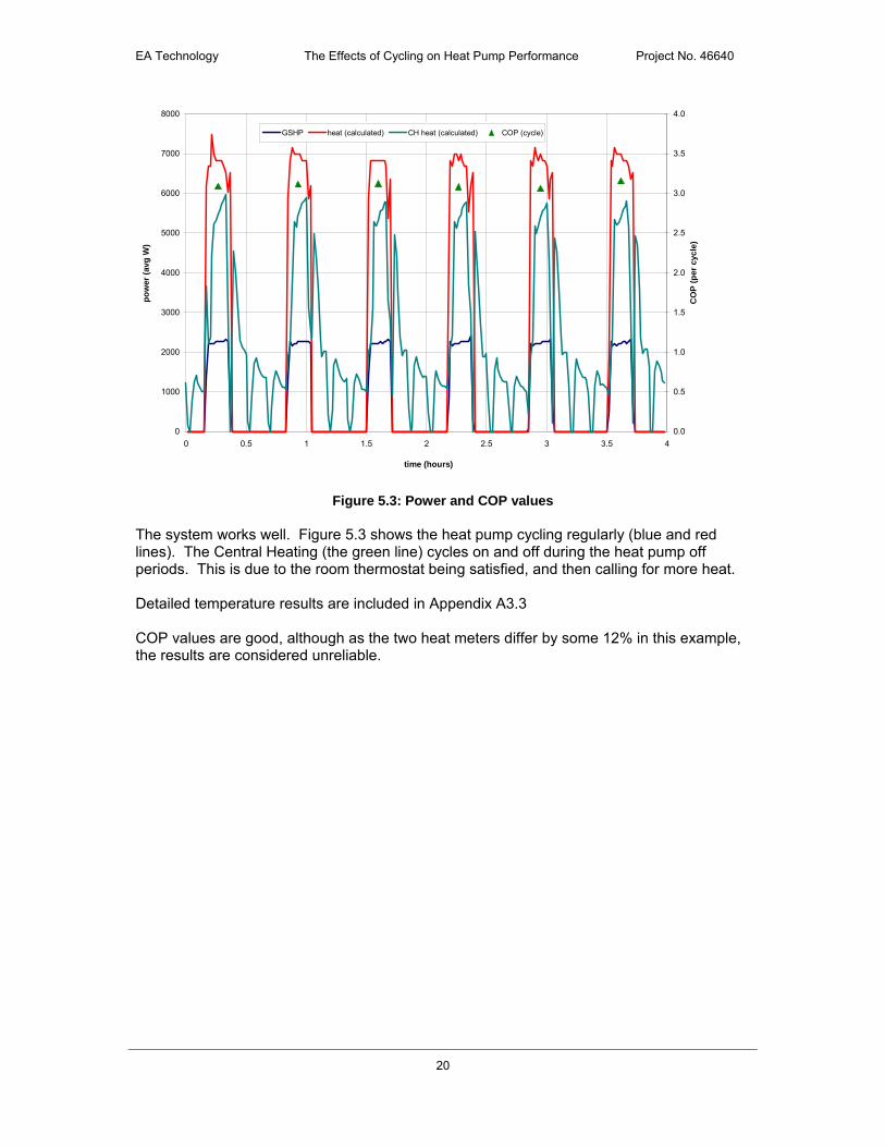
Figure 5.3: Power and COP values The system works well. Figure 5.3 shows the heat pump cycling regularly (blue and red lines). The Central Heating (the green line) cycles on and off during the heat pump off periods. This is due to the room thermostat being satisfied, and then calling for more heat. Detailed temperature results are included in Appendix A3.3 COP values are good, although as the two heat meters differ by some 12% in this example, the results are considered unreliable.

EA Technology The Effects of Cycling on Heat Pump Performance Project No. 46640
21
6 ASHP & buffer tank results
6.1 Forced cycling results
Buffer tank temperatures and heat flows are similar to those seen for the GSHP & buffer tank arrangement – detailed results are presented in Appendices A4.1 and A4.2. A summary of the results is shown in Figure 6.1
0.0
0.5
1.0
1.5
2.0
2.5
3.0
3.5
-6 -4 -2 0 2 4 6 8 10 12 14
ambient temperature
CO
P
long runs - excluding defrostlong runs - including defrostone radiatortwo radiatorstwo radiators - t/statbuffer - one radiatorbuffer - two radiators
Figure 6.1: Comparison of forced cycling buffer results, with and without buffer tank
There is a very clear advantage for the buffer tank arrangement when the system operates with only one radiator open. However, the results are inconclusive for the case where the system has two radiators open, despite the longer run times. Results are summarised below.
Table 6.1: Results for cycling with One Radiator open Ambient
temperatureCOP run time
(minutes)maximum
Tflow (oC)
average CH (W)
6.2 1.78 2.7 47.6 7208.6 1.72 2.9 47.7 94012.0 1.90 2.4 48.9 870
6.1 2.42 12.5 47.8 82012.4 2.62 10.8 48.1 730
No buffer
Buffer
(oC)
EA Technology The Effects of Cycling on Heat Pump Performance Project No. 46640
22
Table 6.2: Results for cycling with Two Radiator open
Ambienttemperature
COP run time(minutes)
maximum
Tflow (oC)
average CH (W)
5.1 2.29 6.5 48.1 1,7206.8 2.40 6.6 48.3 2,11011.4 2.69 5.9 49.9 1,750
5.0 2.45 17.8 46.8 1,6508.5 2.60 16.0 47.2 1,540
No buffer
Buffer
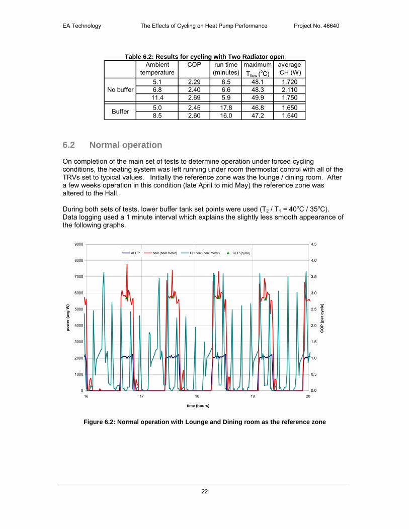
6.2 Normal operation
On completion of the main set of tests to determine operation under forced cycling conditions, the heating system was left running under room thermostat control with all of the TRVs set to typical values. Initially the reference zone was the lounge / dining room. After a few weeks operation in this condition (late April to mid May) the reference zone was altered to the Hall. During both sets of tests, lower buffer tank set points were used (T2 / T1 = 40oC / 35oC). Data logging used a 1 minute interval which explains the slightly less smooth appearance of the following graphs.
0
1000
2000
3000
4000
5000
6000
7000
8000
9000
16 17 18 19 20
time (hours)
po
wer
(av
g W
)
0.0
0.5
1.0
1.5
2.0
2.5
3.0
3.5
4.0
4.5
CO
P (
per
cyc
le)
ASHP heat (heat meter) CH heat (heat meter) COP (cycle)
Figure 6.2: Normal operation with Lounge and Dining room as the reference zone

EA Technology The Effects of Cycling on Heat Pump Performance Project No. 46640
23
0
1000
2000
3000
4000
5000
6000
7000
8000
9000
16 17 18 19 20
time (hours)
po
wer
(av
g W
)
0.0
0.5
1.0
1.5
2.0
2.5
3.0
3.5
4.0
4.5
CO
P (
per
cyc
le)
ASHP heat (calculated) CH heat (calculated) COP (cycle)
Figure 6.3: Normal operation with the Hall as the reference zone
Behaviour is similar in both cases, with clear thermostat cycling of the CH during both heat pump off periods and heat pump on periods. (In both examples, the ambient air temperature was steady at ~ 12oC). Figure 6.4 summarises the results for these “normal” operation periods, in terms of both cycles per day and average daily COP.
0
5
10
15
20
25
30
35
0 5 10 15 20 25
Ambient temperature
No
. o
f cy
cle
s /
day
0.0
0.5
1.0
1.5
2.0
2.5
3.0
3.5
CO
P (
dai
ly a
vera
ge)
cycles - L & D
cycles - hall
COP - L&D
COP - Hall
Figure 6.4: Summary of ASHP and Buffer Tank in normal operation mode
The system appeared to work well throughout. During some of the warmer days, there were periods when the heat pump cycled on whilst there was no demand for CH (i.e. cycling caused solely by the heat loss from the buffer tank). A simple interlock with the room thermostat would overcome this error.
(oC)
(oC)

EA Technology The Effects of Cycling on Heat Pump Performance Project No. 46640
24
7 Discussion and Conclusions It is clear that short cycling reduces the COP of both ASHPs and GSHPs, although the effect is much larger for ASHPs. For the ASHP:
Run time increases with decreasing ambient temperature and with an increase in size of the reference zone;
In the current tests, the 2 radiator reference zone (lounge and dining room) showed a large improvement over the single radiator reference zone during short cycling conditions;
For the GSHP:
The run time increases with the number of fully open radiators in circuits; (Short cycle) run times are very short with both 1 and 2 radiator reference zones (1.6
and 2.4 minutes respectively); The between cycle ground temperature recovery does, however, mitigate against a
severe reduction in COP; COP reduction measured in these tests was ~ 16% in the worst case of the single
radiator reference zone; For both the ASHP and the GSHP, short cycling induced by the room thermostat (rather than the return temperature at the heat pump) can give benefits due to lower flow temperatures. This is particularly the case with the GSHP where such room thermostat induced short cycling gave the best performance of all the GSHP results. However, an accompanying study by Mimer Energy3 explores a number of other reasons why short cycling can be detrimental to heat pump performance. In particular, concerns over compressor reliability, and specifically a need for a minimum run time to ensure the establishment of good oil circulation (in oil lubricated compressor - see Appendix A, reference 3), would seem to rule out this approach in favour of achieving good COP by ensuring that longer run-times are achieved. In this respect, the 4-pipe buffer tank arrangement, as tested here, works well. This produces a separation of the CH from the operation of the heat pump, and allows a much lower flow rate through the CH (when most radiators are closed) compared to the flow rate through the heat pump. In the test results presented here, the CH pattern is significantly altered compared to the non-buffer tank results, although the average (kWh / h) heat delivery is similar in the two cases. Ideally, the buffer tank should achieve a greater degree of stratification than was achieved here, which would tend to keep the CH flow temperature high throughout the heat pump off period, and would, consequently, have less of an impact on the CH pattern. It is difficult to compare the buffer tank results precisely with the non-buffer tank results because of the slight changes in flow temperatures between the systems. However, it is clear that run times are increased through the use of the buffer tank and generally result in an improved COP. (The one exception, in the results presented here, was for the ASHP with the two-radiator reference zone, where run times without the buffer tank were ~ 6 minutes. In this case there was little difference between buffer tank and non-buffer tank COPs).
3 R Curtis and T Pine, “Effects of cycling on domestic GSHPs, Supporting analysis to EA Technology, Simulation / Modelling”, Mimer Energy report No: C207-R2, November 2012

EA Technology The Effects of Cycling on Heat Pump Performance Project No. 46640
25
Whilst this work has focused on the COP under particular conditions of short cycling, no attempt has been made to assess the implications for the annual performance of the system (it could be that such conditions occur so infrequently that the impact on annual performance is negligible). Nevertheless, such short cycling conditions can and do occur, and are more likely to occur in households which aim to minimise energy use by closing down TRVs in rooms that are not occupied.
8 Recommendations Both ASHPs and GSHPs should be designed for a minimum run time of circa six
minutes, which will avoid the worst excesses of detrimental performance caused by short cycling;
Ideally, systems should be designed for slightly higher run times than this – for the
particular GSHP system used here there appears to be an optimum performance at around 10 to 15 minutes, whilst run times of ~ 8 minutes for the ASHP gave COP values close to catalogue steady state values;
Explore all options to achieve these minimum run times including:
o Zoning to ensure sufficient radiator surface is available at all times (as was achieved here by using the lounge / dining room as the reference zone, although a room thermostat override or wide switching band thermostat would also be required to avoid room thermostat induced short cycling);
o Buffer tanks;
The 4-pipe buffer tanks arrangement tested here shows a promising method of achieving the required minimum run times without the need for excessive volumes (roughly 8 litres / kW heat output was used here);
o Ideally the 4-pipe buffer tank would be designed to achieved a high degree of stratification so as to maintain flow temperatures to the CH system throughout the heat pump off periods;
o Care needs to be taken in setting-up a 4-pipe buffer tank system to ensure that the flows through the heat pump and through the fully open CH system are well matched.
EA Technology The Effects of Cycling on Heat Pump Performance Project No. 46640
26
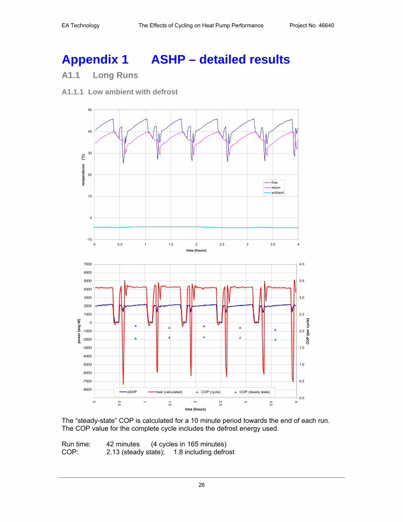
Appendix 1 ASHP – detailed results A1.1 Long Runs
A1.1.1 Low ambient with defrost
-10
0
10
20
30
40
50
0 0.5 1 1.5 2 2.5 3 3.5 4
time (hours)
tem
per
atu
res
flow
return
ambient
-9000
-8000
-7000
-6000
-5000
-4000
-3000
-2000
-1000
0
1000
2000
3000
4000
5000
6000
7000
0 0.5
1 1.5
2 2.5
3 3.5
4
time (hours)
po
wer
(av
g W
)
0.0
0.5
1.0
1.5
2.0
2.5
3.0
3.5
4.0
CO
P (
per
cyc
le)
ASHP heat (calculated) COP (cycle) COP (steady state)
The “steady-state” COP is calculated for a 10 minute period towards the end of each run. The COP value for the complete cycle includes the defrost energy used. Run time: 42 minutes (4 cycles in 165 minutes) COP: 2.13 (steady state); 1.8 including defrost
(o
C)

EA Technology The Effects of Cycling on Heat Pump Performance Project No. 46640
27
A1.1.2 5oC ambient – no defrost
0
5
10
15
20
25
30
35
40
45
50
0 0.5 1 1.5 2 2.5 3 3.5 4
time (hours)
tem
per
atu
res
flow
return
ambient
-1000
0
1000
2000
3000
4000
5000
6000
7000
0 0.5
1 1.5
2 2.5
3 3.5
4
time (hours)
po
wer
(av
g W
)
0.0
0.5
1.0
1.5
2.0
2.5
3.0
3.5
4.0
CO
P (
per
cyc
le)
ASHP heat (calculated) COP (cycle)
Run time: 11 minutes (4 cycles in 71 minutes) COP: 2.48
(o
C)

EA Technology The Effects of Cycling on Heat Pump Performance Project No. 46640
28
A1.1.3 Mild day (12oC)
0
5
10
15
20
25
30
35
40
45
50
0 0.5 1 1.5 2 2.5 3 3.5 4
time (hours)
tem
per
atu
res
flow
return
ambient
-1000
0
1000
2000
3000
4000
5000
6000
7000
0 0.5
1 1.5
2 2.5
3 3.5
4
time (hours)
po
wer
(av
g W
)
0.0
0.5
1.0
1.5
2.0
2.5
3.0
3.5
4.0
CO
P (
per
cyc
le)
ASHP heat (calculated) COP (cycle)
Run time: 9.3 minutes (4 cycles in 87 minutes) COP: 2.89
(o
C)
EA Technology The Effects of Cycling on Heat Pump Performance Project No. 46640
29
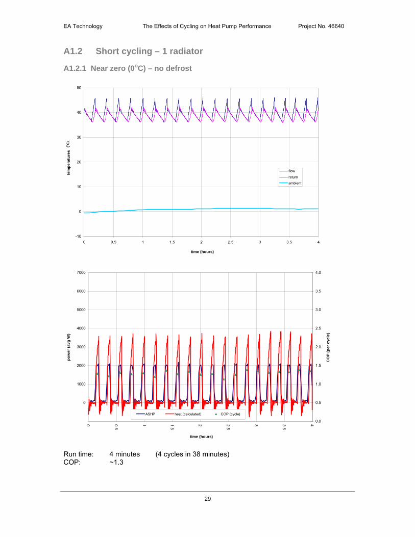
A1.2 Short cycling – 1 radiator
A1.2.1 Near zero (0oC) – no defrost
-10
0
10
20
30
40
50
0 0.5 1 1.5 2 2.5 3 3.5 4
time (hours)
tem
per
atu
res
flow
return
ambient
-1000
0
1000
2000
3000
4000
5000
6000
7000
0 0.5
1 1.5
2 2.5
3 3.5
4
time (hours)
po
wer
(av
g W
)
0.0
0.5
1.0
1.5
2.0
2.5
3.0
3.5
4.0
CO
P (
per
cyc
le)
ASHP heat (calculated) COP (cycle)
Run time: 4 minutes (4 cycles in 38 minutes) COP: ~1.3
(o
C)
EA Technology The Effects of Cycling on Heat Pump Performance Project No. 46640
30
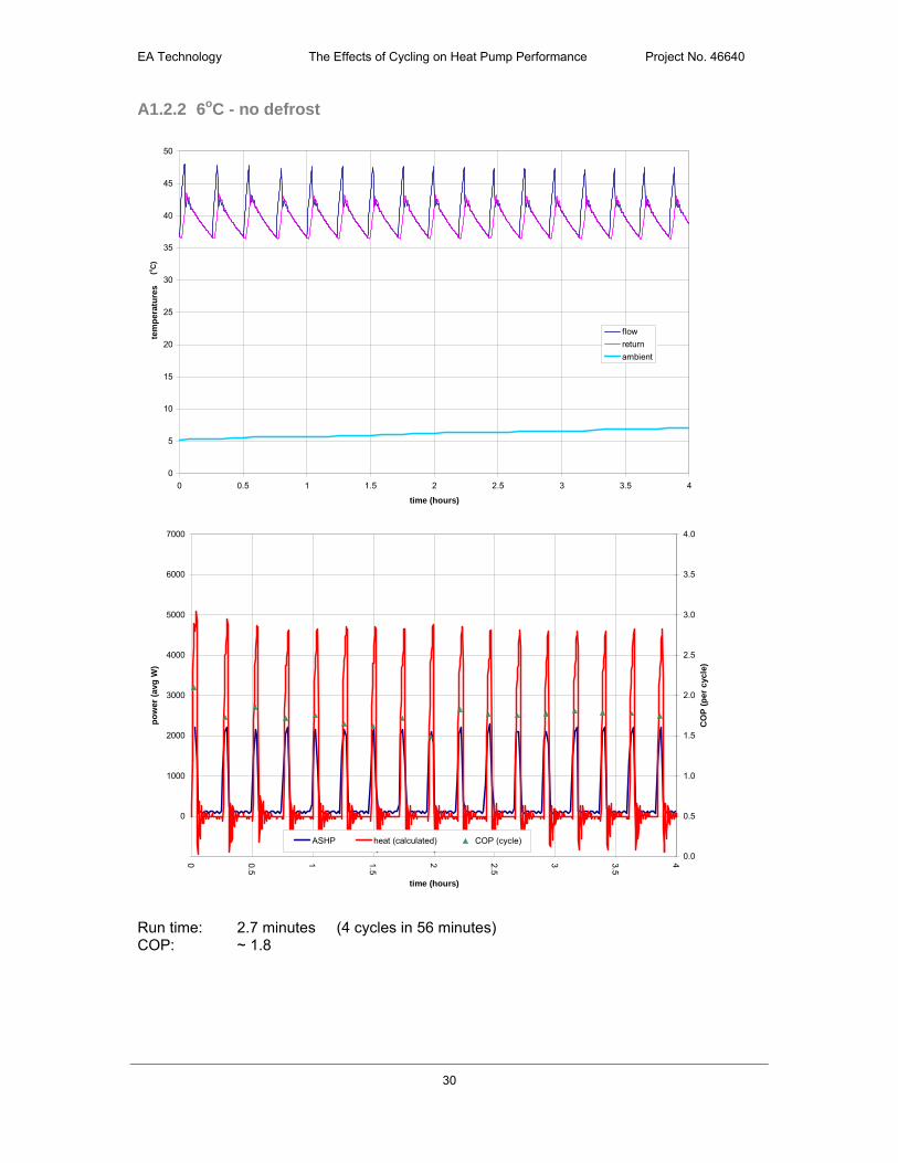
A1.2.2 6oC - no defrost
0
5
10
15
20
25
30
35
40
45
50
0 0.5 1 1.5 2 2.5 3 3.5 4
time (hours)
tem
per
atu
res
flow
return
ambient
-1000
0
1000
2000
3000
4000
5000
6000
7000
0 0.5
1 1.5
2 2.5
3 3.5
4
time (hours)
po
wer
(av
g W
)
0.0
0.5
1.0
1.5
2.0
2.5
3.0
3.5
4.0
CO
P (
per
cyc
le)
ASHP heat (calculated) COP (cycle)
Run time: 2.7 minutes (4 cycles in 56 minutes) COP: ~ 1.8
(o
C)

EA Technology The Effects of Cycling on Heat Pump Performance Project No. 46640
31
A1.2.3 Mild day (12oC)
0
5
10
15
20
25
30
35
40
45
50
0 0.5 1 1.5 2 2.5 3 3.5 4
time (hours)
tem
per
atu
res
flow
return
ambient
-1000
0
1000
2000
3000
4000
5000
6000
7000
0 0.5
1 1.5
2 2.5
3 3.5
4
time (hours)
po
wer
(av
g W
)
0.0
0.5
1.0
1.5
2.0
2.5
3.0
3.5
4.0
CO
P (
per
cyc
le)
ASHP heat (calculated) COP (cycle)
Run time: 2.4 minutes (4 cycles in 43 minutes) COP: ~ 1.9
(o
C)
EA Technology The Effects of Cycling on Heat Pump Performance Project No. 46640
32
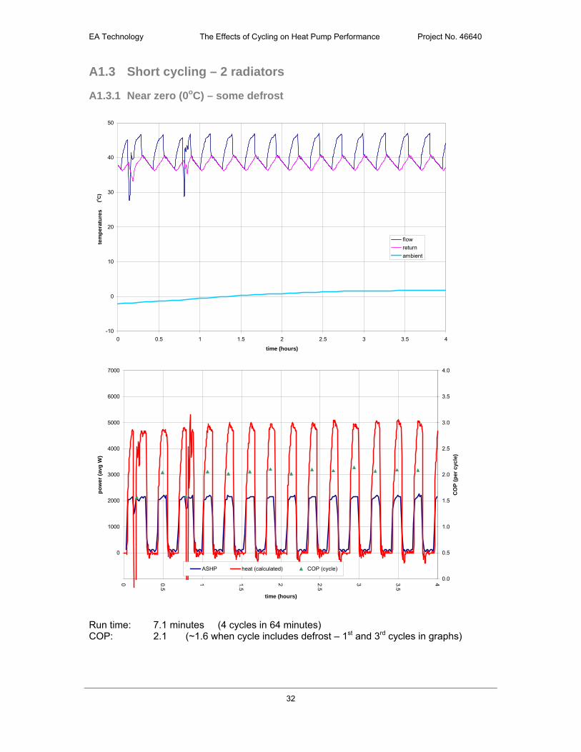
A1.3 Short cycling – 2 radiators
A1.3.1 Near zero (0oC) – some defrost
-10
0
10
20
30
40
50
0 0.5 1 1.5 2 2.5 3 3.5 4
time (hours)
tem
per
atu
res
flow
return
ambient
-1000
0
1000
2000
3000
4000
5000
6000
7000
0 0.5
1 1.5
2 2.5
3 3.5
4
time (hours)
po
wer
(av
g W
)
0.0
0.5
1.0
1.5
2.0
2.5
3.0
3.5
4.0
CO
P (
per
cyc
le)
ASHP heat (calculated) COP (cycle)
Run time: 7.1 minutes (4 cycles in 64 minutes) COP: 2.1 (~1.6 when cycle includes defrost – 1st and 3rd cycles in graphs)
(o
C)

EA Technology The Effects of Cycling on Heat Pump Performance Project No. 46640
33
A1.3.2 7oC - no defrost
0
5
10
15
20
25
30
35
40
45
50
0 0.5 1 1.5 2 2.5 3 3.5 4
time (hours)
tem
per
atu
res
flow
return
ambient
-1000
0
1000
2000
3000
4000
5000
6000
7000
0 0.5
1 1.5
2 2.5
3 3.5
4
time (hours)
po
wer
(av
g W
)
0.0
0.5
1.0
1.5
2.0
2.5
3.0
3.5
4.0
CO
P (
per
cyc
le)
ASHP heat (calculated) COP (cycle)
Run time: 6.6 minutes (4 cycles in 68 minutes) COP: 2.4
(o
C)
EA Technology The Effects of Cycling on Heat Pump Performance Project No. 46640
34
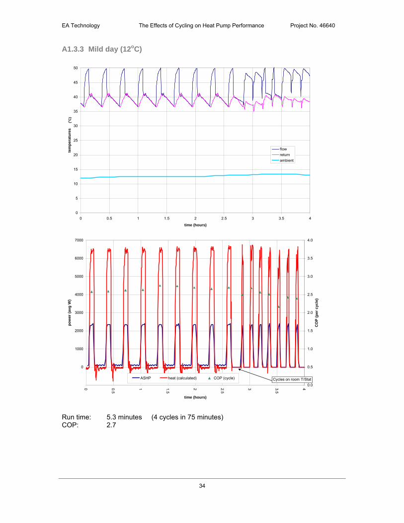
A1.3.3 Mild day (12oC)
0
5
10
15
20
25
30
35
40
45
50
0 0.5 1 1.5 2 2.5 3 3.5 4
time (hours)
tem
per
atu
res
flow
return
ambient
-1000
0
1000
2000
3000
4000
5000
6000
7000
0 0.5
1 1.5
2 2.5
3 3.5
4
time (hours)
po
wer
(av
g W
)
0.0
0.5
1.0
1.5
2.0
2.5
3.0
3.5
4.0
CO
P (
per
cyc
le)
ASHP heat (calculated) COP (cycle) Cycles on room T/Stat
Run time: 5.3 minutes (4 cycles in 75 minutes) COP: 2.7
(o
C)
EA Technology The Effects of Cycling on Heat Pump Performance Project No. 46640
35
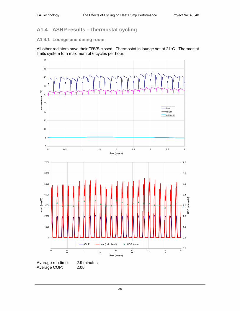
A1.4 ASHP results – thermostat cycling
A1.4.1 Lounge and dining room
All other radiators have their TRVS closed. Thermostat in lounge set at 21oC. Thermostat limits system to a maximum of 6 cycles per hour.
0
5
10
15
20
25
30
35
40
45
50
0 0.5 1 1.5 2 2.5 3 3.5 4
time (hours)
tem
per
atu
res
flow
return
ambient
-1000
0
1000
2000
3000
4000
5000
6000
7000
0 0.5
1 1.5
2 2.5
3 3.5
4
time (hours)
po
we
r (a
vg
W)
0.0
0.5
1.0
1.5
2.0
2.5
3.0
3.5
4.0
CO
P (
pe
r c
yc
le)
ASHP heat (calculated) COP (cycle)
Average run time: 2.9 minutes Average COP: 2.08
(o
C)

EA Technology The Effects of Cycling on Heat Pump Performance Project No. 46640
36
Appendix 2 GSHP – detailed results
A2.1 Continuous
-10
0
10
20
30
40
50
0 0.5 1 1.5 2 2.5 3 3.5 4
time (hours)
tem
per
atu
res
flow
return
Ground In
Ground out
0
1000
2000
3000
4000
5000
6000
7000
8000
9000
0 0.5
1 1.5
2 2.5
3 3.5
4
time (hours)
po
wer
(av
g W
)
0.0
0.5
1.0
1.5
2.0
2.5
3.0
3.5
4.0
4.5
CO
P (
per
cyc
le)
GSHP heat (calculated) COP (cycle)
Run time: continuous COP: 2.87
(o
C)

EA Technology The Effects of Cycling on Heat Pump Performance Project No. 46640
37
A2.2 7 radiators open
0
5
10
15
20
25
30
35
40
45
50
0 0.5 1 1.5 2 2.5 3 3.5 4
time (hours)
tem
per
atu
res
flow
return
Ground In
Ground out
0
1000
2000
3000
4000
5000
6000
7000
8000
9000
0 0.5
1 1.5
2 2.5
3 3.5
4
time (hours)
po
wer
(av
g W
)
0.0
0.5
1.0
1.5
2.0
2.5
3.0
3.5
4.0
4.5
CO
P (
per
cyc
le)
GSHP heat (calculated) COP (cycle)
Run time: 13.5 minutes (4 cycles in 97 minutes) COP: 2.97
(o
C)
EA Technology The Effects of Cycling on Heat Pump Performance Project No. 46640
38
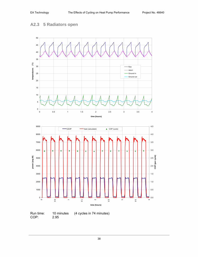
A2.3 5 Radiators open
0
5
10
15
20
25
30
35
40
45
50
0 0.5 1 1.5 2 2.5 3 3.5 4
time (hours)
tem
per
atu
res
flow
return
Ground In
Ground out
0
1000
2000
3000
4000
5000
6000
7000
8000
9000
0 0.5
1 1.5
2 2.5
3 3.5
4
time (hours)
po
wer
(av
g W
)
0.0
0.5
1.0
1.5
2.0
2.5
3.0
3.5
4.0
4.5
CO
P (
per
cyc
le)
GSHP heat (calculated) COP (cycle)
Run time: 10 minutes (4 cycles in 74 minutes) COP: 2.95
(o
C)

EA Technology The Effects of Cycling on Heat Pump Performance Project No. 46640
39
A2.4 4 Radiators open
0
5
10
15
20
25
30
35
40
45
50
0 0.5 1 1.5 2 2.5 3 3.5 4
time (hours)
tem
per
atu
res
flow
return
Ground In
Ground out
0
1000
2000
3000
4000
5000
6000
7000
8000
0 0.5
1 1.5
2 2.5
3 3.5
4
time (hours)
po
wer
(av
g W
)
0.0
0.5
1.0
1.5
2.0
2.5
3.0
3.5
4.0
CO
P (
per
cyc
le)
GSHP heat (calculated) COP (cycle)
Run time: 6 minutes (4 cycles in 55 minutes) COP: 2.87
(o
C)

EA Technology The Effects of Cycling on Heat Pump Performance Project No. 46640
40
A2.5 3 Radiators open
0
5
10
15
20
25
30
35
40
45
50
0 0.5 1 1.5 2 2.5 3 3.5 4
time (hours)
tem
per
atu
res
flow
return
Ground In
Ground out
0
1000
2000
3000
4000
5000
6000
7000
8000
0 0.5
1 1.5
2 2.5
3 3.5
4
time (hours)
po
wer
(av
g W
)
0.0
0.5
1.0
1.5
2.0
2.5
3.0
3.5
4.0
CO
P (
per
cyc
le)
GSHP heat (calculated) COP (cycle)
Run time: 4 minutes (4 cycles in 45 minutes) COP: 2.81
(o
C)

EA Technology The Effects of Cycling on Heat Pump Performance Project No. 46640
41
A2.6 2 Radiators open
0
5
10
15
20
25
30
35
40
45
50
0 0.5 1 1.5 2 2.5 3 3.5 4
time (hours)
tem
per
atu
res
flow
return
Ground In
Ground out
0
1000
2000
3000
4000
5000
6000
7000
8000
0 0.5
1 1.5
2 2.5
3 3.5
4
time (hours)
po
wer
(av
g W
)
0.0
0.5
1.0
1.5
2.0
2.5
3.0
3.5
4.0
CO
P (
per
cyc
le)
GSHP heat (calculated) COP (cycle)
Run time: 2.4 minutes (4 cycles in 37 minutes) COP: 2.68
(o
C)
EA Technology The Effects of Cycling on Heat Pump Performance Project No. 46640
42
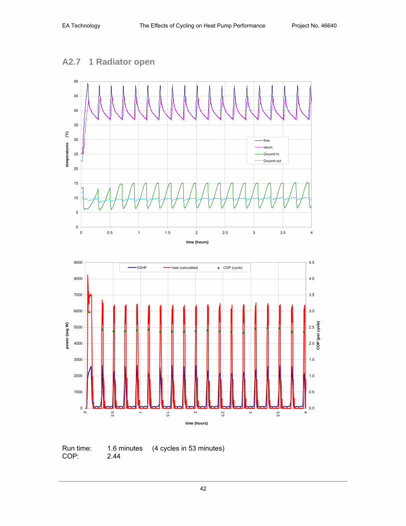
A2.7 1 Radiator open
0
5
10
15
20
25
30
35
40
45
50
0 0.5 1 1.5 2 2.5 3 3.5 4
time (hours)
tem
per
atu
res
flow
return
Ground In
Ground out
0
1000
2000
3000
4000
5000
6000
7000
8000
9000
0 0.5
1 1.5
2 2.5
3 3.5
4
time (hours)
po
wer
(av
g W
)
0.0
0.5
1.0
1.5
2.0
2.5
3.0
3.5
4.0
4.5
CO
P (
per
cyc
le)
GSHP heat (calculated) COP (cycle)
Run time: 1.6 minutes (4 cycles in 53 minutes) COP: 2.44
(o
C)

EA Technology The Effects of Cycling on Heat Pump Performance Project No. 46640
43
A2.8 GSHP results – thermostat cycling
A2.8.1 Lounge and dining room
House set-up for normal use (i.e. radiators with TRVs part open). Reference zone is the lounge / dining room, with the thermostat set to 21oC.
0
5
10
15
20
25
30
35
40
45
50
0 0.5 1 1.5 2 2.5 3 3.5 4
time (hours)
tem
per
atu
res
flow
return
Ground In
Ground out
ambient
0
1000
2000
3000
4000
5000
6000
7000
8000
9000
10000
0 0.5
1 1.5
2 2.5
3 3.5
4
time (hours)
po
wer
(av
g W
)
0.0
0.5
1.0
1.5
2.0
2.5
3.0
3.5
4.0
4.5
5.0
CO
P (
per
cyc
le)
GSHP heat (calculated) COP (cycle)
Average run time: 2.4 minutes Average COP: 3.24 COP significantly above 3 (optimum COP in previous tests).
(o
C)

EA Technology The Effects of Cycling on Heat Pump Performance Project No. 46640
44
A2.8.2 Hall
House set-up for normal use (i.e. radiators with TRVs part open). Reference zone is the hall with the thermostat set to 21oC.
0
5
10
15
20
25
30
35
40
45
50
0 0.5 1 1.5 2 2.5 3 3.5 4
time (hours)
tem
per
atu
res
flow
return
Ground In
Ground out
ambient
0
1000
2000
3000
4000
5000
6000
7000
8000
9000
10000
0 0.5
1 1.5
2 2.5
3 3.5
4
time (hours)
po
wer
(a
vg W
)
0.0
0.5
1.0
1.5
2.0
2.5
3.0
3.5
4.0
4.5
5.0
CO
P (
per
cy
cle
)
GSHP heat (calculated) COP (cycle)
Average run time: 3.9 minutes Average COP: 3.4 COP significantly above 3 (optimum COP in previous tests).
(o
C)

EA Technology The Effects of Cycling on Heat Pump Performance Project No. 46640
45
15
16
17
18
19
20
21
22
23
24
25
0 0.5 1 1.5 2 2.5 3 3.5 4
time
tem
per
atu
re
Hall
Lounge
Dining
Main bed
Graph of room temperatures included to show the difficulty of relying on a non-living area as the reference zone – here the hall is well controlled, but the other rooms are slightly starved of heat.
(o
C)
EA Technology The Effects of Cycling on Heat Pump Performance Project No. 46640
46
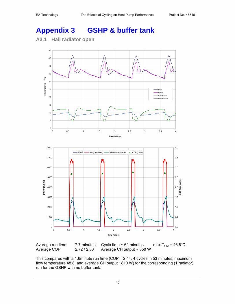
Appendix 3 GSHP & buffer tank A3.1 Hall radiator open
0
5
10
15
20
25
30
35
40
45
50
0 0.5 1 1.5 2 2.5 3 3.5 4
time (hours)
tem
per
atu
res
flow
return
Ground in
Ground out
0
1000
2000
3000
4000
5000
6000
7000
8000
0 0.5 1 1.5 2 2.5 3 3.5 4
time (hours)
po
wer
(av
g W
)
0.0
0.5
1.0
1.5
2.0
2.5
3.0
3.5
4.0
CO
P (
per
cyc
le)
GSHP heat (calculated) CH heat (calculated) COP (cycle)
Average run time: 7.7 minutes Cycle time ~ 62 minutes max Tflow = 46.8oC Average COP: 2.72 / 2.83 Average CH output ~ 850 W This compares with a 1.6minute run time (COP = 2.44, 4 cycles in 53 minutes, maximum flow temperature 48.8, and average CH output ~810 W) for the corresponding (1 radiator) run for the GSHP with no buffer tank.
(o
C)

EA Technology The Effects of Cycling on Heat Pump Performance Project No. 46640
47
Two COP values are given as the heat measured by the CH heat meter is ~4% higher than that measured by the heat meter at the heat pump outlet (see Section 5.1 for further comment on this).
0.0
5.0
10.0
15.0
20.0
25.0
30.0
35.0
40.0
45.0
50.0
0 0.5 1 1.5 2 2.5 3 3.5 4
time (hours)
tem
per
atu
res
Top B2
B3 B4
B5 Bottom
CH flow CH return
The buffer tank temperatures show some stratification after the heat pump switches off, but this is short lived and after around 20 minutes the tank cools as one mass.
A3.2 Lounge and dining room radiators open
0.0
5.0
10.0
15.0
20.0
25.0
30.0
35.0
40.0
45.0
50.0
0 0.5 1 1.5 2 2.5 3 3.5 4
time (hours)
tem
per
atu
res
Top B2
B3 B4
B5 Bottom
CH flow CH return
The cooling curve for the two radiator case is steeper (more radiator surface to dissipate the heat), although there seems to be less stratification of the tank.
(o
C)
(o
C)

EA Technology The Effects of Cycling on Heat Pump Performance Project No. 46640
48
0
5
10
15
20
25
30
35
40
45
50
0 0.5 1 1.5 2 2.5 3 3.5 4
time (hours)
tem
per
atu
res
flow
return
Ground in
Ground out
0
1000
2000
3000
4000
5000
6000
7000
8000
0 0.5 1 1.5 2 2.5 3 3.5 4
time (hours)
po
wer
(av
g W
)
0.0
0.5
1.0
1.5
2.0
2.5
3.0
3.5
4.0
CO
P (
per
cyc
le)
GSHP heat (calculated) CH heat (calculated) COP (cycle)
Average run time: 10.7 minutes Cycle time ~ 44 minutes max Tflow = 46oC Average COP: 2.90 / 3.08 average CH output ~ 1,800 W This compares to a 2.4 minute run time (COP = 2.68, 4 cycles in 37 minutes, maximum flow temperature 48oC, and average CH output of 1,900 W) for the two radiator run with no buffer tank.
(o
C)

EA Technology The Effects of Cycling on Heat Pump Performance Project No. 46640
49
A3.3 Normal operation
All TRVs are open. In this example the Lounge / Dining room is the reference zone (i.e. both TRVs are fully open and the room thermostat is located in the room). All other rooms have part open TRVs with typical settings for normal use. (Upper and Lower buffer tank set-points reduced to 40 and 30oC respectively for these “normal operation” tests).
0
5
10
15
20
25
30
35
40
45
50
0 0.5 1 1.5 2 2.5 3 3.5 4
time (hours)
tem
per
atu
res
flowreturnGround inGround outambient
0
1000
2000
3000
4000
5000
6000
7000
8000
0 0.5 1 1.5 2 2.5 3 3.5 4
time (hours)
po
wer
(av
g W
)
0.0
0.5
1.0
1.5
2.0
2.5
3.0
3.5
4.0
CO
P (
per
cyc
le)
GSHP heat (calculated) CH heat (calculated) COP (cycle)
The lower graph shows the heat pump cycling regularly (blue and red lines). The Central Heating (the green line) cycles on and off during the heat pump off periods. This is due to the room thermostat being satisfied, and then calling for more heat.
(o
C)
EA Technology The Effects of Cycling on Heat Pump Performance Project No. 46640
50
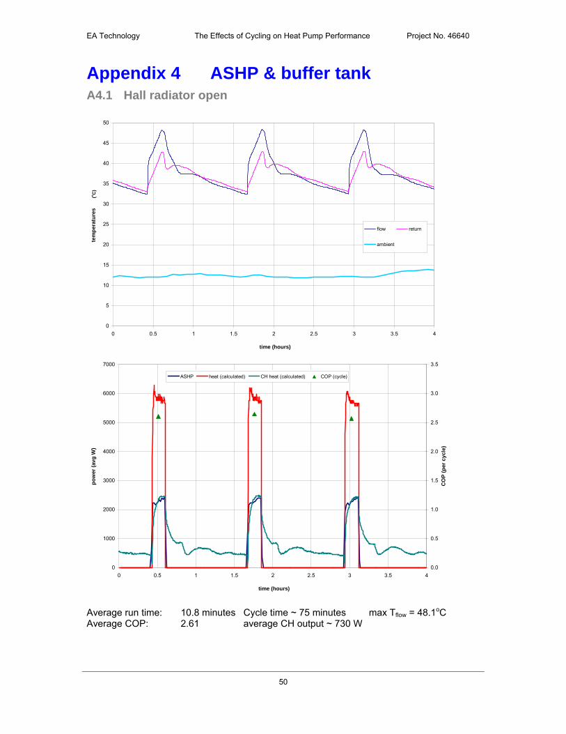
Appendix 4 ASHP & buffer tank A4.1 Hall radiator open
0
5
10
15
20
25
30
35
40
45
50
0 0.5 1 1.5 2 2.5 3 3.5 4
time (hours)
tem
per
atu
res
flow return
ambient
0
1000
2000
3000
4000
5000
6000
7000
0 0.5 1 1.5 2 2.5 3 3.5 4
time (hours)
po
wer
(av
g W
)
0.0
0.5
1.0
1.5
2.0
2.5
3.0
3.5
CO
P (
per
cyc
le)
ASHP heat (calculated) CH heat (calculated) COP (cycle)
Average run time: 10.8 minutes Cycle time ~ 75 minutes max Tflow = 48.1oC Average COP: 2.61 average CH output ~ 730 W
(o
C)

EA Technology The Effects of Cycling on Heat Pump Performance Project No. 46640
51
0.0
5.0
10.0
15.0
20.0
25.0
30.0
35.0
40.0
45.0
50.0
0 0.5 1 1.5 2 2.5 3 3.5 4
time (hours)
tem
per
atu
res
Top B2
B3 B4
B5 Bottom
CH flow CH return
Buffer tank behaviour is similar to that seen for the GSHP.
A4.2 Lounge and dining room radiators open
0
5
10
15
20
25
30
35
40
45
50
0 0.5 1 1.5 2 2.5 3 3.5 4
time (hours)
tem
pe
ratu
res
flow return
ambient
(o
C)
(o
C)

EA Technology The Effects of Cycling on Heat Pump Performance Project No. 46640
52
0
1000
2000
3000
4000
5000
6000
7000
0 0.5 1 1.5 2 2.5 3 3.5 4
time (hours)
po
wer
(av
g W
)
0.0
0.5
1.0
1.5
2.0
2.5
3.0
3.5
CO
P (
per
cyc
le)
ASHP heat (calculated) CH heat (calculated) COP (cycle)
Average run time: 16 minutes Cycle time ~ 57 minutes max Tflow = 47.2oC Average COP: 2.60 average CH output ~ 1,540 W
0.0
5.0
10.0
15.0
20.0
25.0
30.0
35.0
40.0
45.0
50.0
0 0.5 1 1.5 2 2.5 3 3.5 4
time (hours)
tem
per
atu
res
Top B2
B3 B4
B5 Bottom
CH flow CH return
(o
C)