the effects of cross sectional dimensions on the behavior ... · the effects of cross sectional...
TRANSCRIPT

Journal of Civil Engineering and Architecture 10 (2016) 1355-1363 doi: 10.17265/1934-7359/2016.12.006
The Effects of Cross Sectional Dimensions on the
Behavior of L-Shaped RC Structural Members
Mehmet Hasnalbant1 and Cemal Eyyubov2
1. Institute of Natural and Applied Science, Erciyes University, Kayseri 38010, Turkey
2. Department of Civil Engineering, Faculty of Engineering, Erciyes University, Kayseri 38010, Turkey
Abstract: The behavior of L-Shaped RC (reinforced concrete) shear walls was investigated in the Erciyes University Earthquake Investigation Laboratory under the influence of constant axial load together with reversed cyclic lateral load. The objective of this study was to evaluate the effects of cross sectional dimensions on the behavior of L-shaped structural members and to assess their earthquake performance. In order to investigate L-shaped RC structural members, the special experiment setup and four type of 1/2 scaled specimens which have different aspect ratio were constructed. The specimens were loaded in line with the major principal axes direction laterally. Axial load ratio was 0.1 and cross section height to thickness ratios were 3:1, 5:1, 8:1, 10:1. Cross section thickness was 120 mm which corresponds to (360:120), (600:120), (960:120), (1,200:120) wall legs cross sectional dimensions in mm. The specimens height was 1,500 mm, together with upper and lower slabs overall height was 2,000 mm. Concrete compression strength was 30 N/mm2, steel yield stress 420 N/mm2 and vertical reinforcement ratio was 1% for all specimens. According to the test results, the specimen of which the aspect ratio is 3 (360:120) has shown column behavior, the specimen of which the aspect ratio is 5 (600:120) has shown slender wall behavior and last two specimens of which the aspect ratios are 8 (960:120) and 10 (1,200:120) have shown squat wall behavior. When considering the cracking patterns and hysteretic behavior, since the aspect ratio 8, the specimens show flexure-shear interaction behavior and prone to brittle failure. Key words: Shear wall, reinforced concrete, L-shaped, ductility, stiffness.
1. Introduction
Shear walls are frequently used to resist lateral
forces. Because of their high strength and stiffness,
they can effectively reduce lateral displacements and
limit damages of structural and non structural elements.
Although planar walls commonly are used and can
prevent buildings from collapse, sometimes it is
necessary to use more efficient lateral load resisting
systems to provide required performance level. As the
tools for conducting nonlinear response history have
improved with the advent of performance based
seismic design, reinforced concrete walls and core
walls are often employed as the only lateral force
resisting system [1].
Because of the architectural, lateral stiffness
Corresponding author: Cemal Eyyubov, professor,
research fields: steel structures, earthquake engineering and structural dynamic.
necessities, to maximize the window space, designers
may prefer non planar shear walls. L-shaped shear
walls are formed by combining two orthogonal planar
shear walls and have two directional strength and
stiffness. Considering the response of these wall
components along each of the principle plan direction
separately is not reasonable. Combining the planar
walls leads to unsymmetric bending and complicated
interaction between wall parts. Responses of non
planar walls with at least one cross sectional principal
axes that is not a symmetry axis are typically governed
by unsymmetric bending and would be influenced by
inelastic biaxial interactions more significantly than
those of planar walls [2].
Stiffness, strength and ductility of shear walls with
asymmetric cross section can be completely different
and can exhibit different failure mode in opposite
directions [3].
D DAVID PUBLISHING

The Effects of Cross Sectional Dimensions on the Behavior of L-Shaped RC Structural Members
1356
1.1 Numerical Studies in Literature
The strength and deformational behavior of
L-shaped tied columns have been studied by Hsu [4]
under combined biaxial bending and axial compression
experimentally and analytically. Dündar [5] has been
proposed an approach to the ultimate strength
calculation and the dimensioning of arbitrarily shaped
RC (reinforced concrete) sections subject to combined
biaxial bending and axial compression. Rodriguez [6]
offered a general formulation by which the biaxial
interaction diagrams of an arbitrary reinforced concrete
cross sections. The proposed method uses nonlinear
stress-strain relationship for the concrete and
multi-linear elastoplastic one for the reinforcement. So
it can be utilized to study the effects of creep and
confinement of the concrete and strain hardening of the
steel by modifying the input parameters. Khairallah [7]
presented numerical model for the prediction of three
dimensional characteristics of reinforced concrete
L-shaped shear wall structures. Orakçal [8]
investigated modeling approaches for reliable
prediction of reinforced concrete wall response. They
proposed multiple vertical line element macro
model.
1.2 Experimental Studies in Literature
Nakachi [9] investigated deformation capacity of
multistory reinforced concrete core walls after flexural
yielding. Four core walls were constructed and tested.
Test parameters were the concrete confinement at the
corner, the amount of confining steel at the corner and
the area of concrete confinement. They have found that
confining reinforcement at the corner had significant
effect on deformation capacity.
Hosaka [10] investigated structural performance of
L-shaped shear walls experimentally and analytically
by using fiber model. They produced 1/6 scaled four
specimens. Lateral load was applied under varied axial
loads. Parameters were concrete strength and rebar
arrangement. Due to the test results, flexural
deformations at the section about 1L (L is the height
which is equal to the wall length) from the bottom
were dominant.
Inada [11] constructed three L-shaped core wall with
1/4.5 scale. They studied the effect of loading direction
and the section configuration on the seismic behavior
of the core wall. The wall that was loaded in the arm
direction failed due to crushing of boundary zone in
compression. Other unequal leg wall’s damage was
more effective in the short leg. Strain distribution was
not linear in the section. The hypothesis of plane
sections remaining plane was not valid. They
recommended increasing the confinement area at the
corner of the section.
Karamlou [12] tested 1/2 scaled, four L-shaped
shear walls which were built with industrialized
reinforced insulating concrete form panels. They
investigated the behavior of L-shaped shear wall
constructed with this system. The specimens had the
same geometrical dimensions but differed in their
confining boundary rebars. Dimensions of the
specimens were 1,500 mm high, 750 mm wide and 100
mm thick. They have found that web crushing reduces
the stiffness, strength and ductility, on the other hand,
increases the rotation of shear walls, higher flexural
strength of the walls in one direction against the other,
increases the possibility of web crushing.
Li [13] tested L-shaped cross section shear walls of
which the height-thickness ratio is between 5-8. They
constructed six specimens and loaded in the web plane.
Axial load ratio was in the range of 0.1~0.4 . They have
found that the specimen, of which the axial load ratio is
0.1 and height-thickness ratio is 6.5, has the most
excellent ductility and energy dissipation capacity.
2. Experimental Study
Four different cross section dimensioned, 1/2 scaled
reinforced concrete specimens were constructed and
tested.
The compressive strength of concrete was
30 N/mm2, steel yield stress was 420 N/mm2, the cross
section thickness of all specimens were 120 mm, and

The Effects of Cross Sectional Dimensions on the Behavior of L-Shaped RC Structural Members
1357
the height of all specimens was 1,500 mm.
Additionally, 200 mm thick upper slab was constructed
for vertical load, 300 mm thick lower slab was
constructed for foundation. Initially, 0.1Acfc axial load
was applied at centroid and kept constant during test.
After the vertical load reaching the required level, the
cyclic lateral load was applied at the major principal
axes direction for all specimens:
Ac = cross sectional concrete area;
fc = concrete compression strength on the test day.
Specimens design parameters are given in Table 1
and cross section size and reinforcement are shown in
Fig. 1.
2.1 Specimens Construction
Specimens were constructed by on-site casting with
wood formwork in the Erciyes University Earthquake
Investigation Laboratory. 10 mm diameter vertical
reinforcement with 0.01 volumetric ratio and 8 mm
diameter horizontal reinforcement with 0.0072
volumetric ratio were used in the specimens.
Reinforcement yield stress was 420 MPa.
Table 1 Specimens characteristics.
Notation Cross section dimension (mm)
Cross section ratio
Shear span ratio
Axial load ratio
Vertical reinforcement ratio
Horizontal reinforcement ratio
Concrete strength
L120x360 120 × 360 × 360 3 4.17 0.06 0.013 0.0072 37 N/mm2
L120x600 120 × 600 × 600 5 2.5 0.10 0.012 0.0072 21 N/mm2
L120x960 120 × 960 × 960 8 1.56 0.09 0.012 0.0072 21 N/mm2
L120x1200 120 × 1,200 × 1,200 10 1.25 0.05 0.011 0.0072 37 N/mm2
Fig. 1 Specimens cross sections and reinforcements (units in mm).
360
L120x360
360
120
12? 0
960
L120x960
960
120
32? 0
1200
L120x1200
1200
120
40? 0
600
L120x600
600
120
20? 0

The Effects of Cross Sectional Dimensions on the Behavior of L-Shaped RC Structural Members
1358
2.2 Test Setup
The reaction frame was constructed by using steel
profiles. The frame is hinged at the lower end and can
move together with the specimens upper slab. The
finished steel plate was placed at the vertical load
applied joint on the upper slab. The special end element
was produced for the vertical hydraulic jacks junction
point with the steel plate. While the lateral loading,
tension force was transmitted to the other side of the
specimens through two steel rods.
The vertical load was applied at the cross section
centroid by a 1,000 kN hydraulic jack that was
mounted on top girder of the reaction frame. To create
biaxial bending effect, lateral load was applied in line
with major principle axes direction of the specimens.
To apply the lateral load, another 1,000 kN hydraulic
jack was connected between top slab of the specimens
and the reaction wall horizontally. By placing a hinge
between hydraulic jack and the top slab bending
moment, the displacements were released.
2.3 Measuring Instruments
In the experiment, load cells, strain gauges, LVDTs
(linear variable displacement transducers),
potentiometer, dial gauges were used as a measuring
devices. Applied vertical and horizontal loads were
measured by load cells during the test. Horizontal and
vertical displacements were measured by LVDTs,
potentiometer, dial gauges. Additionally, some strain
gauges were mounted on boundary reinforcement to
monitor the yielding and strain process.
2.4 Loading Protocol
In the experiments, the axial load upper limit was
adopted as 500 kN for safety reasons. Therefore, the
largest specimens axial load was taken as 500 kN. At
first, the entire vertical load was divided in 8 to10 times
and applied gradually. Deal gauges values were read
and recorded at each step. After reaching the full axial
load, horizontal load began to apply. When calculating
the cyclic load increment for each specimen, it was
considered to reach their lateral load capacity in 10 steps.
Fig. 2 Reinforcement.
Fig. 3 Test setup.

The Effects of Cross Sectional Dimensions on the Behavior of L-Shaped RC Structural Members
1359
Fig. 4 Lateral loading protocol.
Fig. 5 L120x360 cracking pattern.
Concrete crushing or reinforcement buckling was
considered to ultimate load capacity.
Corresponding lateral load increment for each
specimens are as follows:
L120x360 5kN;
L120x600 10kN;
L120x960 20kN;
L120x1200 30kN.
3. Experimental Results
In this section, experimental results including
cracking pattern, hysteretic behavior, ductility factor of
each specimen are presented.
3.1 Cracking Patterns
For the specimen L120x360, under the cyclic
loading, only horizontal bending crack was formed and
Fig. 6 L120x600 cracking pattern.
Fig. 7 L120x960 cracking pattern.
-390
-290
-190
-90
10
110
210
310
1 3 5 7 9 111315171921232527For
ce(k
N)
Load Step
Lateral Loading
L120x1200
L120x960
L120x600
L120x360

The
1360
Fig. 8 L120x
Fig. 9 Analy
e Effects of Cr
x1200 cracking
ytical model.
ross Section
g pattern.
al Dimensionns on the Beh
no
the
F
ben
the
long
con
she
crac
and
in l
failu
F
hor
app
she
effe
was
leng
form
T
spre
The
plas
mem
inte
T
gen
3.2
D
whi
(Eq
(∆u
whe
+
-∆
-∆
+
-μ
havior of L-Sh
shear cracks
bending mom
For the spec
nding cracks w
specimen. T
ger at the lo
ntinuously i
ar-flexure c
cks were long
d negative dir
length due to
ure was obse
For the sp
izontal bend
plying higher
ar cracks app
ective than be
s observed.
gth and distan
mation of com
To the specim
ead througho
erefore it has
stic hinge re
mber is und
eraction and p
Three dimen
nerated by usi
Ductility Beh
Displacement
ich is summ
q. (1)) by usin
u) displaceme
ere: +∆y = po
+∆u = positiv
∆y = negative
∆u = negativ
+μ = positive
μ = negative
haped RC Str
was observe
ment effect an
imen L120x
were observe
These horizo
ower region
increasing
racks appea
ger than inclin
ection horizo
o different neu
rved.
pecimen L12
ding crack w
r levels of la
peared and s
ending stress.
When consi
nce between
mpression stru
men L120x12
out whole su
not been po
egion in the
der the infl
prone to brittl
nsional finit
ing solid and
havior
t ductility fac
marized in T
ng the top sla
ents in each di
μ = ∆u/
ositive directi
e direction ul
e direction yi
e direction ul
direction duc
direction duc
ructural Mem
d. The specim
nd behaves li
x600, the fir
ed at the corn
ontal flexure
of the specim
lateral loa
ared. Horizo
ned shear cra
ontal cracks w
utral axes dep
20x960, ini
was observe
ateral load, l
shear stress b
. Shear-flexur
idering the
them, it is po
ut in diagona
200, diagonal
urface of th
ssible to form
specimen. S
luence of sh
le failure.
te element
link elements
ctors (μ) of th
Table 2 wer
ab yield (∆y)
irections.
/∆y
ion yield disp
ltimate displa
ield displacem
ltimate displa
ctility factor;
ctility factor.
bers
men is under
ke column.
st horizontal
ner region of
cracks was
men. Due to
ad, inclined
ontal flexure
acks. Positive
were different
pth. Bending
itially short
d but when
long inclined
became more
re interaction
shear cracks
ossible to see
al direction.
shear cracks
he specimen.
mation of the
So, structural
hear-moment
model was
s (Fig. 9).
he specimens
re calculated
and ultimate
(1)
placement;
acement;
ment;
acement;
r
l
f
s
o
d
e
e
t
g
t
n
d
e
n
s
e
s
.
e
l
t
s
s
d
e
)

The
Table 1 Duc
Notation
L120x360
L120x600
L120x960
L120x1200
3.3 Hysteret
-150
For
ce(k
N)
-50
For
ce(k
N)
e Effects of Cr
ctility factors.
+∆y
11mm
10.4mm
3.8mm
5.3mm
tic Behavior
-100 -
D
L120x
-
-
-30
D
L120
ross Section
+∆u
44mm
40.7mm
15.8mm
24.7mm
(a)
(c)
(e)
-100
-50
0
50
100
-50 0
Displacement
x360 Test hys
-150
-100
-50
0
50
100
150
-10 10
Displacement(
0x600 Test Hy
al Dimension
-∆y
7.7mm
7.7mm
3.5mm
4mm
50
t(mm)
steresis loop
30
(mm)
ysteresis Loo
ns on the Beh
-∆u
25.6mm
23mm
10mm
14.7mm
100
50
op
havior of L-Sh
+μ
m 4
3.91
4.15
m 4.66
haped RC Str
-μ
3.3
2.9
2.8
3.6
(b)
(d)
(f)
ructural Mem
m
32 3
98 3
86 3
68 4
bers 1361
mean μ
.66
.45
.50
4.17
The Effects of Cross Sectional Dimensions on the Behavior of L-Shaped RC Structural Members
1362
(g) (h)
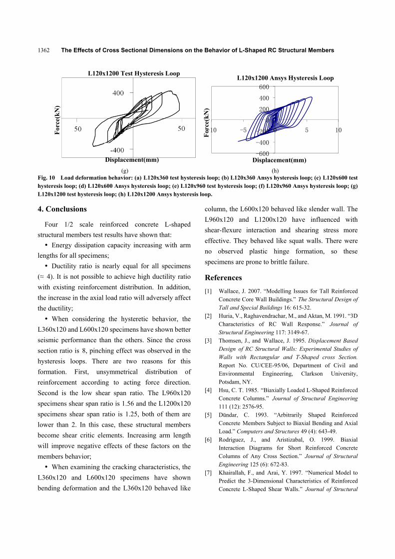
Fig. 10 Load deformation behavior: (a) L120x360 test hysteresis loop; (b) L120x360 Ansys hysteresis loop; (c) L120x600 test hysteresis loop; (d) L120x600 Ansys hysteresis loop; (e) L120x960 test hysteresis loop; (f) L120x960 Ansys hysteresis loop; (g) L120x1200 test hysteresis loop; (h) L120x1200 Ansys hysteresis loop.
4. Conclusions
Four 1/2 scale reinforced concrete L-shaped
structural members test results have shown that:
Energy dissipation capacity increasing with arm
lengths for all specimens;
Ductility ratio is nearly equal for all specimens
(≈ 4). It is not possible to achieve high ductility ratio
with existing reinforcement distribution. In addition,
the increase in the axial load ratio will adversely affect
the ductility;
When considering the hysteretic behavior, the
L360x120 and L600x120 specimens have shown better
seismic performance than the others. Since the cross
section ratio is 8, pinching effect was observed in the
hysteresis loops. There are two reasons for this
formation. First, unsymmetrical distribution of
reinforcement according to acting force direction.
Second is the low shear span ratio. The L960x120
specimens shear span ratio is 1.56 and the L1200x120
specimens shear span ratio is 1.25, both of them are
lower than 2. In this case, these structural members
become shear critic elements. Increasing arm length
will improve negative effects of these factors on the
members behavior;
When examining the cracking characteristics, the
L360x120 and L600x120 specimens have shown
bending deformation and the L360x120 behaved like
column, the L600x120 behaved like slender wall. The
L960x120 and L1200x120 have influenced with
shear-flexure interaction and shearing stress more
effective. They behaved like squat walls. There were
no observed plastic hinge formation, so these
specimens are prone to brittle failure.
References
[1] Wallace, J. 2007. “Modelling Issues for Tall Reinforced Concrete Core Wall Buildings.” The Structural Design of Tall and Special Buildings 16: 615-32.
[2] Huria, V., Raghavendrachar, M., and Aktan, M. 1991. “3D Characteristics of RC Wall Response.” Journal of Structural Engineering 117: 3149-67.
[3] Thomsen, J., and Wallace, J. 1995. Displacement Based Design of RC Structural Walls: Experimental Studies of Walls with Rectangular and T-Shaped cross Section. Report No. CU/CEE-95/06, Department of Civil and Environmental Engineering, Clarkson University, Potsdam, NY.
[4] Hsu, C. T. 1985. “Biaxially Loaded L-Shaped Reinforced Concrete Columns.” Journal of Structural Engineering 111 (12): 2576-95.
[5] Dündar, C. 1993. “Arbitrarily Shaped Reinforced Concrete Members Subject to Biaxial Bending and Axial Load.” Computers and Structures 49 (4): 643-49.
[6] Rodriguez, J., and Aristizabal, O. 1999. Biaxial Interaction Diagrams for Short Reinforced Concrete Columns of Any Cross Section.” Journal of Structural Engineering 125 (6): 672-83.
[7] Khairallah, F., and Arai, Y. 1997. “Numerical Model to Predict the 3-Dimensional Characteristics of Reinforced Concrete L-Shaped Shear Walls.” Journal of Structural
-600
-400
-200
0
200
400
600
-10 -5 0 5 10
For
ce(k
N)
Displacement(mm)
L120x1200 Ansys Hysteresis LoopL120x1200 Test Hysteresis Loop
For
ce(k
N)
Displacement(mm)
The Effects of Cross Sectional Dimensions on the Behavior of L-Shaped RC Structural Members
1363
Construction Engineering 493: 73-81. [8] Orakçal, K., Massone, L., and Wallace, J. 2006. Analytical
Modeling of Reinforced Concrete Walls for Predicting Flexural and Coupled Shear-Flexural Responses. PEER Report 2006/07. University of California, Los Angeles, USA.
[9] Nakachi, T., Toda, T., and Tabata, K. 1996. “Experimental Study on Deformation Capacity of Reinforced Concrete Core Walls after Flexural Yielding.” In Proceedings of the 11th World Conference on Earthquake Engineering .
[10] Hosaka, G., Funaki, H., Hosoya, H., and Imai, H. 2008. “Experimental Study on Structural Performance of RC Shear Wall with L-Shaped Section.” In Proceedings
of the 14th World Conference on Earthquake Engineering.
[11] Inada, K., Chosa, K., Sato, H., Kono, S., and Watanabe, F. 2008. “Seismic Performance of RC L-Shaped Core Structural Walls.” In Proceedings of the 14th World Conference on Earthquake Engineering.
[12] Karamlou, A., and Kabir, M. Z. 2012. “Experimental Study of L-Shaped Slender R-ICF Shear Walls under Cyclic Lateral Loading.” Engineering Structures 36: 134-46.
[13] Li, W., and Li, Q.-N. 2012. “Seismic Performance of L-Shaped RC Shear Wall Subjected to Cyclic Loading.” The Structural Design of Tall and Special Buildings 21 (12): 855-66.