the effect of fluid injection on an experimental fault and its ... ••• methods •••...
TRANSCRIPT

The effect of fluid injection on an experimental fault and its role on frictional stability and earthquake triggering
Scuderi M.M.1, Collettini C.1,2 and C. Marone3
European Research CouncilSeventh Framework Programme
“Ideas” Starting GrantGLASS: 259256
European Union Horizon 2020 research and innovation programme
Marie Sklodowska-Curie FEAT No. 656676
1 La Sapienza University of Rome 2 Istituto Nazionale di Geofisica e Vulcanologia (INGV), Rome
3 Pennsylvania State University, USA

Introduction •••
Methods •••
Results - RSF ••
Results - fault slip ••••
Results - fault porosity •
Discussion •••••
Summary
Important to understand the interaction between fluids and faulting
Val D`Agri oil field, Italy Wastewater-induced seismicity (ML > 2)
Seismicity relates to main peaks in the well-head injection pressure and shows a migration
on a pre-existing fault confined within the Apulian carbonates.
Improta et al., 2015 GRL
Oklahoma, USA Wastewater-induced seismicity (many events Mw > 5)
Wastewater injection increased seismicity rate dramatically
Keranen et al., 2014 Science

Fault Reactivation vs. Frictional Slip Stability
The increase in fluid pressure along a fault will decrease the effective normal stress that clamps the fault in place favoring fault reactivation
Hubbert and Rubey, 1959 Bull. Geol.Soc. Am
ΔPf
Failure Criteria
FaultReactivation
Shea
r Str
ess (τ)
Effective normal stress (σ’n)
τ = µ (σn - Pf )
σnτ
kck
Fault Stress Profile
Pf
Wastewater Injection
Impermeable Layer
AncientFault
Acquifer
Fluid Pressure
(Pf )
Fault Clampingstress (σ‘n)
Pf
ΔPf
k/Kc>1<1 Unstable
Stable
CarbonateReservoir
Introduction •••
Methods •••
Results - RSF ••
Results - fault slip ••••
Results - fault porosity •
Discussion •••••
Summary
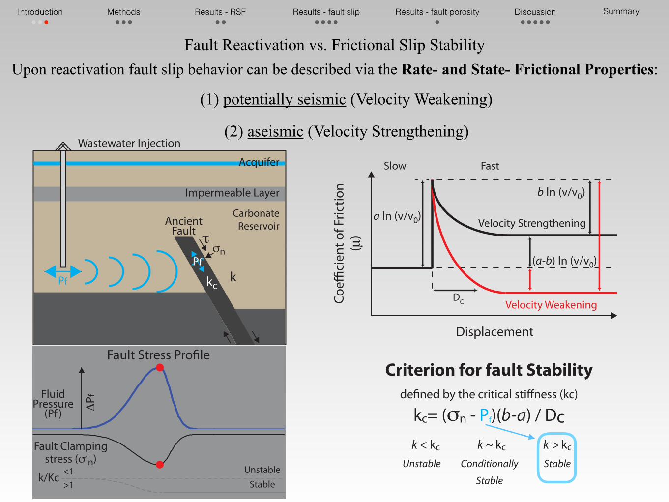
Criterion for fault Stabilitydefined by the critical stiffness (kc)
kc= (σn - Pf)(b-a) / Dck > kc k ~ kc k < kc Stable Conditionally
Stable
Unstable
Upon reactivation fault slip behavior can be described via the Rate- and State- Frictional Properties:
(1) potentially seismic (Velocity Weakening)
(2) aseismic (Velocity Strengthening)
σnτ
kck
Fault Stress Profile
Pf
Wastewater Injection
Impermeable Layer
AncientFault
Acquifer
Fluid Pressure
(Pf )
Fault Clampingstress (σ‘n)
Pf
ΔPf
k/Kc>1<1 Unstable
Stable
CarbonateReservoir
Coeffi
cien
t of F
rictio
n (µ
)
a ln (v/v0)
(a-b) ln (v/v0)
DC
Displacement
Velocity Strengthening
Velocity Weakening
b ln (v/v0)
Slow Fast
Introduction •••
Methods •••
Results - RSF ••
Results - fault slip ••••
Results - fault porosity •
Discussion •••••
Summary
Fault Reactivation vs. Frictional Slip Stability

Biaxial Apparatus in a Double Direct Shear configuration
within a Pressure Vessel
Collettini et al., 2014 IJRM; Scuderi and Collettini, 2016 Nature Scientific Report
Introduction •••
Methods •••
Results - RSF ••
Results - fault slip ••••
Results - fault porosity •
Discussion •••••
Summary

Up-streamPpu
Down-streamPpdShear
stress
Normal stress
Porous Frits
Latex tubes
Latex boots
O-RingGouge Layers
Double Direct Shear configuration within a pressure vessel
Sample assembly
Conduits for fluids
Porous FritsLatex jacket
5.5 cm
5cm
Introduction •••
Methods •••
Results - RSF ••
Results - fault slip ••••
Results - fault porosity •
Discussion •••••
Summary

Double Direct Shear configuration within a pressure vessel
Sample assembly
Conduits for fluids
Porous FritsLatex jacket
5.5 cm
5cm
Introduction •••
Methods •••
Results - RSF ••
Results - fault slip ••••
Results - fault porosity •
Discussion •••••
Summary
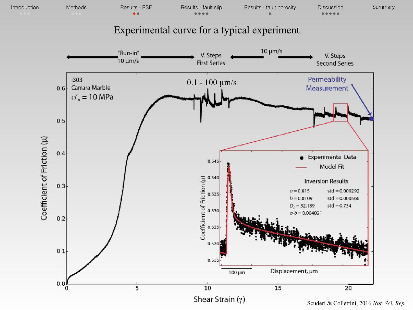
Experimental curve for a typical experiment
0.1 - 100 µm/s
Scuderi & Collettini, 2016 Nat. Sci. Rep.
Introduction •••
Methods •••
Results - RSF ••
Results - fault slip ••••
Results - fault porosity •
Discussion •••••
Summary

Scuderi & Collettini, 2016 Nat. Sci. Rep.
The friction rate parameter (a-b) decreases as the pore fluid pressure is increased
The parameter Dc decreases as pore fluid
pressure is increased from sub-hydrostatic to near lithostatic conditions
Critical Slip Distance - Dc
Velocity dependence of friction (a-b)
-0.002
0
0.002
0.004
0.006
0.008
0.01
0 5 10 15
v = 0.1 - 1 m/sv = 1 - 10 m/sv = 10 - 100 m/s
(a-b)
Effective Normal Stress (σ’n), MPa
λ = Pf / σn
Marble GougePc = 19 MPa
0 5 10 15 20
0.10.20.30.40.50.60.70.80.9
0
20
40
60
80
100
120
0 5 10 15
0.10.20.30.40.50.60.70.80.9
Effective Normal Stress (σ’n), MPa
λ = Pf / σn
Criti
cal S
lip D
istan
ce (D
c), µ
m
v = 0.1 - 1 m/sv = 1 - 10 m/sv = 10 - 100 m/s
Marble GougePc = 19 MPa
Pf increase
Pf increase
Introduction •••
Methods •••
Results - RSF ••
Results - fault slip ••••
Results - fault porosity •
Discussion •••••
Summary
sub-hydrostaticNear lithostatic

Creep experiments
Constant Normal stress
Constant Shear stress
We monitor fault slip
Pc is constant
Pf is increased stepwise
Scuderi et al., 2017 EPSL
Shea
r Str
ess (
τ), M
Pa
Time, minutesU
p-St
ream
flui
d pr
essu
re, M
Pa
Constant PfInjection 1MPa/hInjection 0.2MPa/12min
λ = 0.4λ increases
(1) (2) (3) Creep test
Steady State Shear Strength (τss)90% τss
80% τss
Failure
(1) Constant displacement rate of 10 µm/s to localize shear
(2) Fault relaxation to residual strength
(3) Set the shear stress at the desired value in load control to monitor fault slip
Introduction •••
Methods •••
Results - RSF ••
Results - fault slip ••••
Results - fault porosity •
Discussion •••••
Summary

Shea
r Str
ess (
τ), M
Pa
Time, minutesU
p-St
ream
flui
d pr
essu
re, M
Pa
Constant PfInjection 1MPa/hInjection 0.2MPa/12min
λ = 0.4λ increases
(1) (2) (3) Creep test
Steady State Shear Strength (τss)90% τss
80% τss
13151719Fluid Pressure, MPa
Perm
eabi
lity,
m2
Shea
r Str
ess (
τ), M
Pa
Effective Normal Stress (σ’n), MPa
τ = 0.19 + 0.55 σ’n
(1)
creep test
Failure Envelope
Failure
Creep experiments
Three types of experiments to characterize fault slip behavior:
1) Constant Pf to monitor undisturbed fault creep 2) Injection of fluids at 1 MPa every hour 3) Injection of fluids at 0.2 MPa every 12 min
Introduction •••
Methods •••
Results - RSF ••
Results - fault slip ••••
Results - fault porosity •
Discussion •••••
Summary

Creep Experiments - 90%𝛕ss
An increase in pore fluid pressure
causes fault reactivation and failure with fault slip reaching slip velocities of
1 to 2 mm/s
1) Primary creep least for 35-40min in the experiment before injection begun
2) Secondary creep aseismic creep at v~50nm/s corresponding to strain rates of 2×10⁻⁴ s-1
3) Tertiary creep begin when we meet the criterion for reactivation the acceleration preceding dynamic failure least for ~1h
Scuderi et al., 2017 EPSL
Introduction •••
Methods •••
Results - RSF ••
Results - fault slip ••••
Results - fault porosity •
Discussion •••••
Summary

90%𝛕ss 80%𝛕ss
Introduction •••
Methods •••
Results - RSF ••
Results - fault slip ••••
Results - fault porosity •
Discussion •••••
Summary
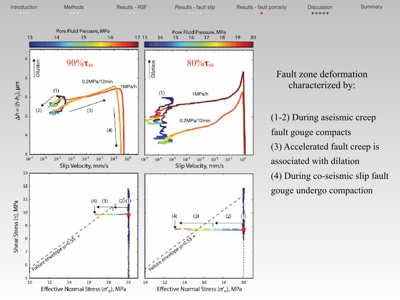
(1-2) During aseismic creep fault gouge compacts (3) Accelerated fault creep is associated with dilation (4) During co-seismic slip fault gouge undergo compaction
Fault zone deformation characterized by:
90%𝛕ss 80%𝛕ss
Introduction •••
Methods •••
Results - RSF ••
Results - fault slip ••••
Results - fault porosity •
Discussion •••••
Summary
1MPa/h
0.2MPa/12min
1MPa/h0.2MPa/12min
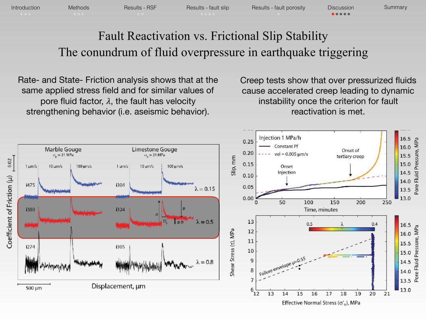
Fault Reactivation vs. Frictional Slip StabilityThe conundrum of fluid overpressure in earthquake triggering
Rate- and State- Friction analysis shows that at the same applied stress field and for similar values of
pore fluid factor, 𝜆, the fault has velocity strengthening behavior (i.e. aseismic behavior).
Creep tests show that over pressurized fluids cause accelerated creep leading to dynamic
instability once the criterion for fault reactivation is met.
Introduction •••
Methods •••
Results - RSF ••
Results - fault slip ••••
Results - fault porosity •
Discussion •••••
Summary

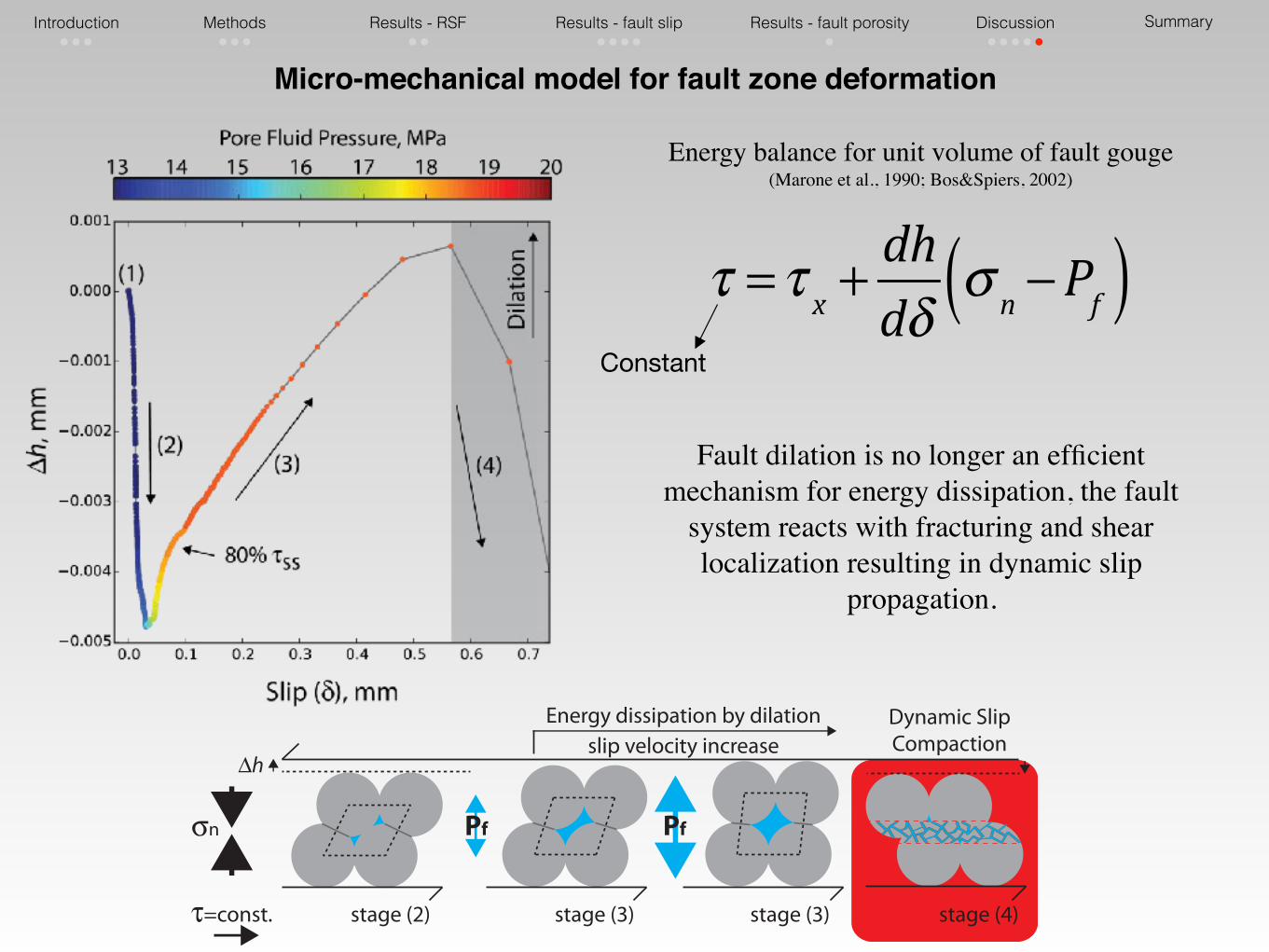
Energy balance for a representative unit volume of fault gouge(Marone et al., 1990; Bos&Spiers, 2002)
Micro-mechanical model for fault zone deformation
τ = τ x +dhdδ
σ n −Pf( )
τ = τ x +dεdγ
σ n −Pf( )dεdγ
dhdδ
For our experimental configuration
Shear Stressduring creep experiments is imposed at constant values
represents the sum of all microscale dissipative processes per unit volume that include grain fracture, frictional sliding of grain contacts, pressure solution and crystal plasticity.
Volumetric variations per unit of slip
Effective Stress
Introduction •••
Methods •••
Results - RSF ••
Results - fault slip ••••
Results - fault porosity •
Discussion •••••
Summary

τ = τ x +dhdδ
σ n −Pf( )
stage (2) stage (3) stage (4)
σn
τ=const.
Pf Pf
∆h
Energy dissipation by dilation slip velocity increase
stage (3)
Dynamic SlipCompaction
Energy balance for unit volume of fault gouge(Marone et al., 1990; Bos&Spiers, 2002)
Constant
Increases due to microscale dissipative
processes such as pressure solution
Constant
To maintain the energy balance fault gouge
compacts
Micro-mechanical model for fault zone deformation
Introduction •••
Methods •••
Results - RSF ••
Results - fault slip ••••
Results - fault porosity •
Discussion •••••
Summary

τ = τ x +dhdδ
σ n −Pf( )Constant
Micro-mechanical model for fault zone deformation
stage (2) stage (3) stage (4)
σn
τ=const.
Pf Pf
∆h
Energy dissipation by dilation slip velocity increase
stage (3)
Dynamic SlipCompaction
Energy balance for unit volume of fault gouge(Marone et al., 1990; Bos&Spiers, 2002)
The effective stress decreases due to fault
pressurization causing a energy imbalance
The fault must dilate to dissipate the
energy
Introduction •••
Methods •••
Results - RSF ••
Results - fault slip ••••
Results - fault porosity •
Discussion •••••
Summary
τ = τ x +dhdδ
σ n −Pf( )Constant
Micro-mechanical model for fault zone deformation
stage (2) stage (3) stage (4)
σn
τ=const.
Pf Pf
∆h
Energy dissipation by dilation slip velocity increase
stage (3)
Dynamic SlipCompaction
Energy balance for unit volume of fault gouge(Marone et al., 1990; Bos&Spiers, 2002)
Fault dilation is no longer an efficient mechanism for energy dissipation, the fault
system reacts with fracturing and shear localization resulting in dynamic slip
propagation.
Introduction •••
Methods •••
Results - RSF ••
Results - fault slip ••••
Results - fault porosity •
Discussion •••••
Summary

Pore fluid pressurization can promote accelerated fault slip in fault gouge that is characterized by velocity strengthening behavior (i.e. aseismic creep).
Fault slip behavior is well described by an energy balance that consider the interaction between fault zone deformation and surrounding stress field .
Summary:
Thank youMail: [email protected]
The duality between the rate strengthening behavior and the observed nucleation of dynamic instability can be interpreted by considering the different dynamics of micro mechanical processes and stress state evolution between creep experiments and constant displacement rate experiment used to retrieve RSF parameters.

Pore fluid pressurization can promote accelerated fault slip in fault gouge that is characterized by velocity strengthening behavior (i.e. aseismic creep).
Fault slip behavior is well described by an energy balance that considers the interaction between the fault zone deformation and the surrounding stress field .
Summary:
Thank youMail: [email protected]
The nucleation of dynamic instability on a rate strengthening fault can be due to the different dynamics of micro mechanical processes and stress state evolution between creep experiments and constant displacement rate experiment that are used to retrieve RSF parameters.