the effect of shear strength on the ballistic response of laminated composite plates
TRANSCRIPT

at SciVerse ScienceDirect
European Journal of Mechanics A/Solids 42 (2013) 35e53
Contents lists available
European Journal of Mechanics A/Solids
journal homepage: www.elsevier .com/locate/ejmsol
The effect of shear strength on the ballistic response of laminatedcomposite plates
K. Karthikeyan a,*, B.P. Russell a, N.A. Fleck a, H.N.G. Wadley b, V.S. Deshpande a
aDepartment of Engineering, University of Cambridge, Trumpington Street, Cambridge CB2 1PZ, UKbDepartment of Material Science & Engineering, School of Engineering and Applied Science, University of Virginia, Charlottesville, VA 22903, USA
a r t i c l e i n f o
Article history:Received 8 February 2013Accepted 11 April 2013Available online 28 April 2013
Keywords:Ballistic limitScaling lawsComposites
* Corresponding author. Tel.: þ44 (0)1223748525.E-mail address: [email protected] (K. Karthikeyan
0997-7538/$ e see front matter � 2013 Elsevier Mashttp://dx.doi.org/10.1016/j.euromechsol.2013.04.002
a b s t r a c t
The ballistic performance of clamped circular carbon fibre reinforced polymer (CFRP) and Ultra HighMolecular Weight Polyethylene (UHMWPE) fibre composite plates of equal areal mass and 0/90� lay-upwere measured and compared with that of monolithic 304 stainless steel plates. The effect of matrixshear strength upon the dynamic response was explored by testing: (i) CFRP plates with both a cured anduncured matrix and (ii) UHMWPE laminates with identical fibres but with twomatrices of different shearstrength. The response of these plates when subjected to mid-span, normal impact by a steel ball wasmeasured via a dynamic high speed shadowmoiré technique. Travelling hinges emanate from the impactlocation and travel towards the supports. The anisotropic nature of the composite plate results in thehinges travelling fastest along the fibre directions and this results in square-shaped moiré fringes in the0/90� plates. Projectile penetration of the UHMWPE and the uncured CFRP plates occurs in a progressivemanner, such that the number of failed plies increases with increasing velocity. The cured CFRP plate, ofhigh matrix shear strength, fails by cone-crack formation at low velocities, and at higher velocities by acombination of cone-crack formation and communition of plies beneath the projectile. On an equal arealmass basis, the low shear strength UHMWPE plate has the highest ballistic limit followed by the highmatrix shear strength UHMWPE plate, the uncured CFRP, the steel plate and finally the cured CFRP plate.We demonstrate that the high shear strength UHMWPE plate exhibits Cunniff-type ballistic limit scaling.However, the observed Cunniff velocity is significantly lower than that estimated from the laminateproperties. The data presented here reveals that the Cunniff velocity is limited in its ability to charac-terise the ballistic performance of fibre composite plates as this velocity is independent of the shearproperties of the composites: the ballistic limit of fibre composite plates increases with decreasingmatrix shear strength for both CFRP and UHMWPE plates.
� 2013 Elsevier Masson SAS. All rights reserved.
1. Introduction
Structures made from fibre composites are finding increasingapplication in light-weight ships, vehicles and aircraft. In additionto their structural performance, ballistic resistance may also be arequirement. The projectiles might be fragments and other suchthreats that are directed at vehicles in military applications, orfragments from roads or runways and other debris in commercialand civilian applications. The fibre composites used for ballisticapplications are typically Carbon Fibre Reinforced Polymer (CFRP)composites which primarily serve a structural function but also areexpected to provide ballistic protection. Kevlar and other aramid
).
son SAS. All rights reserved.
composites, and more recently composites made from Ultra HighMolecular Weight Polyethylene (UHMWPE) fibres, are increasinglyused for impact resistance but these tend to be parasitic in weightand serve little structural function.
Ultra High Molecular Weight Polyethylene (UHMWPE) fibreswere commercialised in the late 1970s by DSM Dyneema, NL underthe trade name Dyneema� and more recently by Honeywell in theUSA under the name Spectra. Both fibres have densities less thanthat of water (rf ¼ 970 kg m�3) and tensile strengths in excess of3 GPa (Hearle, 2001; Vlasblom and Dingenen, 2009). Their veryhigh specific strength has led to their use in high performance sails,fishing lines and marine mooring cables, and woven fabrics areused to make protective gloves. A rationale for their use in ballisticapplications has been presented by Cunniff (1999). Cunniff (1999)argued that the ballistic limit of fibre composites scales linearlywith the so-called Cunniff velocity c* of the fibre as defined by

Table 1Constituent and construction details for the four laminate material systems.
Laminate Fibre Matrix Lay-up & Fibre volume
K. Karthikeyan et al. / European Journal of Mechanics A/Solids 42 (2013) 35e5336
c* ¼ sf 3f
2rf
ffiffiffiffiffiEfrf
s !1=3
(1)
thickness h fraction Vf
HB26 SK76Ø17.0 mm
Polyetherdiol-aliphaticdiisocyanate polyurethane
[0�/90�]48h ¼ 6 mm
0.83
HB50 SK76Ø15.7 mm
Styrene-isoprene-styrenetriblock copolymer
[0�/90�]54h ¼ 6 mm
0.82
CFRP-C IM7Ø 5 mm
Epoxy fiberite 934(cured e 2h@120 �C, 6 Bar)
[(0�/90�)70�]h ¼ 3.75 mm
0.55
CFRP-U IM7Ø 5 mm
Epoxy fiberite 934 (uncured) [(0�/90�)70�]h ¼ 4 mm
0.55
where sf and 3f are the tensile failure strength and failure strain ofthe fibres respectively, while Ef is the tensile modulus of the fibres.Candidate ballistic materials are plotted in Fig. 1 using axes ofspecific energy absorption and longitudinal wave speed. Contoursof constant Cunniff velocity c* are included in this plot. This metricsuggests that Dyneema� fibres (SK60, SK76, etc.) and Spectra� fi-bres considerably outperform most other fibres including Kevlarand armour steels, supporting their use in ballistic applications.
A number of studies have been conducted to measure the static(Wilding and Ward, 1978, 1981, 1984; Jacobs et al., 2000; Govaertand Lemstra, 1992; Peijs et al., 1990; Govaert et al., 1993; Krommet al., 2003; Dessain et al., 1992) and dynamic response (Huanget al., 2004; Koh et al., 2008, 2010; Benloulo et al., 1997) ofUHMWPE fibres and composites. For example, Russell et al. (2013)have observed that UHMWPE composites have tensile strengths ofa few GPa and a shear strength on the order of a fewMPa.Moreover,they found that the tensile strength of UHMWPE fibres displaysnearly no strain rate dependence for strain rates up to 103 s�1. Suchmeasurements have been used to develop continuum models(Grujicic et al., 2009, 2009a; Iannucci and Pope, 2011) to enable themodelling of penetration resistance of UHMWPE composites.Penetration calculations performed using such constitutive models(Frissen,1996; Grujicic et al., 2009, 2009a; Iannucci and Pope, 2011)are able to reproduce observations to varying degrees of success buttypically give little insight into the physical basis of the scalingrelation as proposed by Cunniff (1999). In an elegant analyticalstudy, Phoenix and Porwal (2003) demonstrated that the ballisticlimit of composite plates scales with c* by assuming a membranestretching deformation and failure mode of the impacted plate.
There is now growing anecdotal evidence that the matrix shearstrength (which governs the inter-laminar shear strength) and theconsolidation pressure affect the ballistic performance of UHMWPEcomposites. For example, Greenhalgh et al. (2013) have recently
Fig. 1. Materials typically used for ballistic protection applications plotted in longitu-dinal wave speed e specific energy absorption space. Contours of constant Cunniffvelocity c* are included to indicate the best ballistic materials.
reported a highly detailed fractography study that illustrates theeffect of consolidation pressure and shear strength upon the energyabsorption and failure mechanisms such as delamination andsplitting. However, matrix shear strength does not affect the valueof c* and so any observed dependence of ballistic limit upon shearstrength violates Cunniff scaling. On the other hand, Wei et al.(2013a, 2013b) illustrated inter-lamina delamination is the majormaterial damage mechanism in E-glass/vinylester compositepanels while performing a numerical calculations to study theirunderwater blast response. To date, no systematic studies thatquantify the effect of shear strength upon the deformation andpenetration response of composite plates have been reported. Thisstudy attempts to address this gap in the literature.
We choose two 0�/90� composite laminates with awide range ofmatrix shear strength: (i) CFRP and (ii) Dyneema� UHMWPElaminate. In each case we vary the shear strength of the compositeby changing the matrix properties while keeping the fibre type,volume fraction and thereby the value of c* fixed. This enables us toinvestigate whether the Cunniff velocity is sufficient to characterisethe deformation and penetration responses of these composites.Results are also presented for the impact response of stainless steelplates of equal areal mass in order to provide a baselinecomparison.
2. Materials and properties
Two types of fibre laminates are investigated: (i) UHMWPElaminates as manufactured by DSM1 and (ii) CFRP laminates asmanufactured by Hexcel Composites Ltd.2 Two variants of each ofthese composites were employed and their designations, fibre andmatrix types, lay-ups and volume fraction Vf of fibres are listed inTable 1. A brief description of the manufacturing route for thesecomposites is now presented.
2.1. DSM Dyneema composites
Two types of 0�/90� laminates, with commercial designationsHB26 and HB50, were procured from DSM. The two composites aresimilar in most respects, as seen in Table 1; however, the poly-urethane matrix in HB26 harder than the Kraton rubber matrix inthe HB50 composite. The composites are manufactured in 3 steps:
Step I: Fibres are produced by a gel-spinning/hot drawing pro-cess (Smith et al., 1979, 1980). The UHMWPE is dissolved in asolvent at a temperature of 150 �C and the solution is pumpedthrough a spinneret containing a few hundred capillaries inorder to form liquid filaments. These liquid filaments are thenquenched inwater to form a gel-fibre. The gel-fibre is drawn at a
1 DSM Dyneema B.V., Mauritslaan 49, 6129 EL Urmond, The Netherlands.2 Hexcel Composites Ltd., Ickleton Road Cambridge CB22 4QD.

K. Karthikeyan et al. / European Journal of Mechanics A/Solids 42 (2013) 35e53 37
strain rate on the order of 1 s�1 in hot air (at 120 �C), resulting ina highly oriented (crystalline) fibre of diameter 17 mm.Step II: Fibres are aligned into tows, coated in matrix resin so-lution and are then formed into a [0�/90�/0�/90�] stack. Thestack is dried to remove the matrix solvent.Step III: The [0�/90�/0�/90�] stack is cut, laid-up to the requiredthickness and hot pressed (20 MPa at 120 �C). Bonding of thelayers is achieved by the matrix material. The fibre diameter isunchanged by the hot-pressing operation, although a propor-tion of the fibres change their cross-sectional shape.
2.2. CFRP laminates
CFRP pre-preg, comprising unidirectional IM7 carbon fibres inan epoxy resin (fiberite 934), was obtained from Hexcel CompositesLtd., and is denoted by the trade name Hexply� 8552/33%/134/IM7(12 K). Two composites, with identical lay-ups as detailed in Table 1,were manufactured. The so-called cured composite was subjectedto the standard cure cycle for this resin system (2 h at 120 �C, heldunder 600 kPa pressure) and is labelled CFRP-C. The uncuredcomposite was left in its pre-preg state and was stored at �15 �C; itis termed CFRP-U, and was thawed at room temperature for 5 hprior to testing.
In addition, 0.71 mm thick cold-rolled 304 stainless steel plateswere subjected to quasi-static and ballistic testing, to provide areference material against which the performance of the compositesystems can be compared. All plates (steel and composite) had anareal mass of approximately 5.89 kg m�2 with plate thicknesses assummarised in Table 1.
2.3. Measurement of material properties
Standard dog-bone shaped specimens were used tomeasure theuniaxial tensile response of the 304 stainless steel at an appliedstrain rate of 10�3 s�1. A more comprehensive series of tests wereconducted on the four 0�/90� composites:
(i) Uniaxial tensile tests were performed in the 0�/90� orientationsuch that the 0� plies were aligned with the tensile axis. TheUHMWPE and CFRP-U laminates have a high tensile strengthalong the fibre directions, but a very low shear strength (bothin-plane and out-of-plane). Thus, a standard tabbed tensilespecimen cannot be used to measure the stress versus strainresponse of a 0�/90� composite. Here, we follow the approachof Russell et al. (2013) andmake use of a specimenwith a largegripping area and a narrow gauge length, as sketched in
Fig. 2. Sketches of the specimens used to measure (a) the tensile responses of the laminatedouble-notch shear specimen. All dimensions are in mm.
Fig. 2a. The tensile tests were conducted in a screw driven testmachine at a nominal applied strain rate of 10�3 s�1 with thenominal stress determined from the test machine load cell.The axial nominal strain was measured using a clip gauge ofgauge length 12.5mm. For the CFRP-C composites, tensile testswere conducted as per the ASTM standard D3039 at an appliedstrain rate of 10�3 s�1.
(ii) Tensile tests were performed on the composites with fibresaligned in the�45� orientationwith respect to the tensile axis.While no special specimen geometries were needed, we usesthe same specimen geometries and procedure as thoseemployed for the 0�/90� tensile tests.
(iii) Double-notch shear tests were used to measure the inter-laminar shear response, see Fig. 2b. These tests were con-ducted using the double-notch specimen geometries (Danieland Ishai, 2005; Liu et al., 2013) as modified to suit theextreme anisotropy of the composites considered. Specifically,strips of length 150 mm, width b ¼ 20 mm and thicknessh ¼ 6 mmwere cut from the UHMWPE and the uncured CFRPsheets. Inter-laminar shear deformation was promoted over agauge length of length l ¼ 30 mm by drilling one hole and 2notches over the central section of the specimen, as sketchedin Fig. 2b. Carewas taken to ensure that the hole/notches werepositioned so that no fibres spanned the entire length of thespecimen. The tests were conducted by friction gripping thespecimen ends and pulling them as indicated in Fig. 2b in ascrew driven test machine at a displacement rate of 1 mm/minand 500 mm/min. The inter-laminar shear stress szx wasdefined as szx h P/(2lb), where P is the measured tensile loadand the factor of 2 accounts for the fact that shear loadingoccurs over 2 inter-laminar planes, as shown in Fig. 2b. Theshear displacement across the inter-laminar planes wasmeasured bymounting a clip gauge on either side of the notchas indicated in Fig. 2b. The above procedure was used tomeasure the inter-laminar shear properties of the HB26, HB50and CFRPU composites. In contrast, the CFRP-C composite hasa high shear strength and preliminary double-notch testsresulted in a mode-II fracture of the specimen. We concludethat the double-notch shear test is not suitable for extractionof the inter-laminar shear stress versus displacementresponse.
The tensile stress versus strain curves of the UHMWPE and CFRPlaminates in the 0�/90� are plotted in Fig. 3a along with that of the304 stainless steel. In this orientation, all the composites display anapproximately elasticebrittle response as the behaviour is domi-nated by the fibres. Hence, the HB26 and HB50 UHMWPE
s in the 0�/90� and �45� orientations and (b) the inter-laminar shear response using a

Fig. 3. The measured tensile stress versus strain responses of the (a) CFRP and UHMWPE laminates in the 0�/90� orientation as well as the 304 stainless steel. The correspondingresponses in the �45� orientation for the (b) HB26, (c) HB50 and CFRP-U and (d) CFRP-C composites. All the response are for an applied strain rate of 10�3 s�1. The matrix yieldstrength is indicated on (b) to (d) by sy.
K. Karthikeyan et al. / European Journal of Mechanics A/Solids 42 (2013) 35e5338
composites have similar responses, as do the cured and uncuredCFRP composites. In contrast, the 304 stainless steel has a stronglyhardening elastice plastic response; the tensile ductility of the 304stainless steel is about 60% but for the sake of clarity we truncatethe data in Fig. 3a at a tensile strain of 2%.
The tensile responses of the CFRP and UHMWPE composites inthe�45� orientations, are plotted in Fig. 3b through to d, again for astrain rate of 10�3 s�1. The responses are now dominated by matrixshear. Hence, the strength of the composites is significantly lowerthan in the 0�/90� orientation and the composites exhibit a higherductility in the �45� orientation. The HB26, HB50 and the CFRP-Ucomposites have a relatively soft matrix and display considerableductility (in excess of 20%) and we first consider these materials.After initial yield (denoted by sy in Fig. 3), the composites continueto deform by scissoring of the fibres oriented at �45� with respectto the tensile axis. The resulting rotation of the fibres aligns themtowards the tensile axis. This gives rise to a geometric hardeningresponse as seen in Fig. 3 b and c, with the composites finally failingby matrix cracking and the fibres remaining intact. The CFRP-U and
HB50 composites have similar strengths while the HB26 composite(which has a stronger matrix) exhibits a higher strength but lowerductility. On the other hand the CFRP-C composite (Fig. 3d) displaysa nearly elastic perfectly plastic responsewith a significantly higherstrength of approximately 160 MPa and a relatively low ductility of4%. The CRFP-C composite also fails bymatrix cracking with no fibrerupture.
The inter-laminar shear response of the composites that possessa “soft” matrix (i.e. uncured CFRP, HB26 and HB50) are plotted inFig. 4 for displacement rates of 1 mm/min and 500 mm/min of thedouble-notch shear tests. In each case, the measured shearresponse has considerable rate dependence. Also, the peak shearstrength, as measured in the inter-laminar shear test is approxi-mately half the initial tensile yield strength of composites in the�45� orientation; compare Figs. 3 and 4. We emphasise, however,that this test cannot be used to characterise the strength versusshear strain rate dependence of the composites as the strain ratecannot be defined due to localisation of strain as shown via DigitalImage Correlation by Karthikeyan et al. (2013).
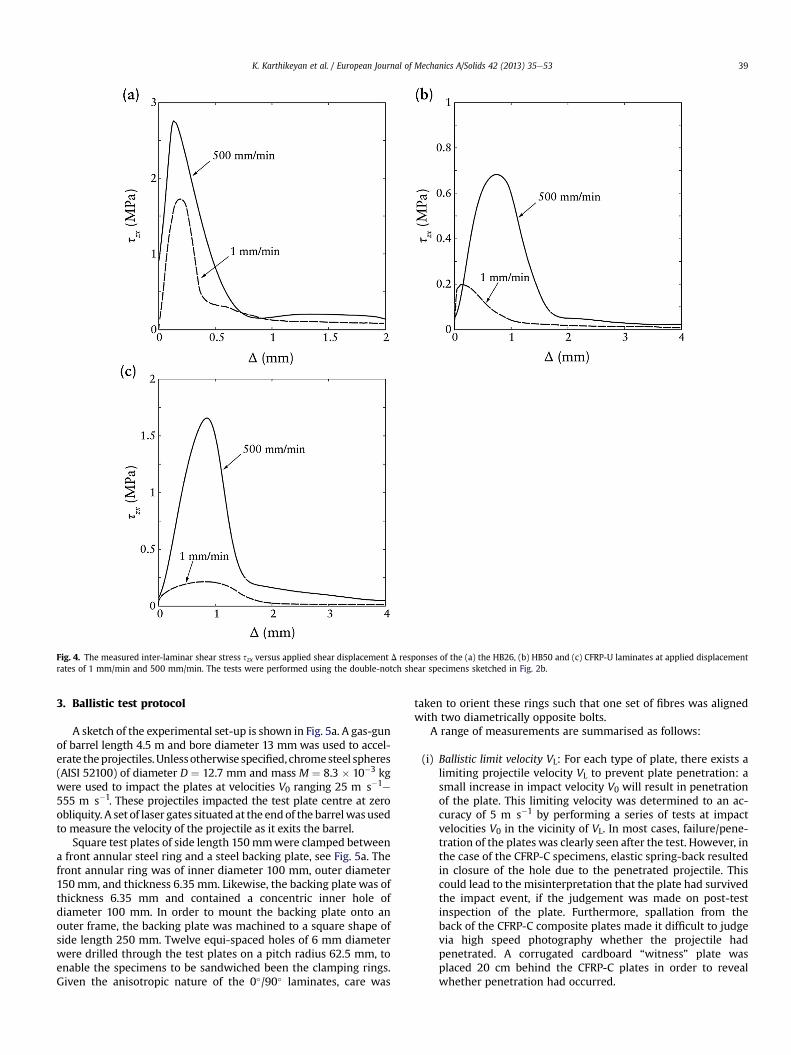
Fig. 4. The measured inter-laminar shear stress szx versus applied shear displacement D responses of the (a) the HB26, (b) HB50 and (c) CFRP-U laminates at applied displacementrates of 1 mm/min and 500 mm/min. The tests were performed using the double-notch shear specimens sketched in Fig. 2b.
K. Karthikeyan et al. / European Journal of Mechanics A/Solids 42 (2013) 35e53 39
3. Ballistic test protocol
A sketch of the experimental set-up is shown in Fig. 5a. A gas-gunof barrel length 4.5 m and bore diameter 13 mm was used to accel-erate theprojectiles.Unlessotherwise specified, chromesteel spheres(AISI 52100) of diameter D ¼ 12.7 mm and mass M ¼ 8.3 � 10�3 kgwere used to impact the plates at velocities V0 ranging 25 m s�1e
555 m s�1. These projectiles impacted the test plate centre at zeroobliquity. A set of laser gates situated at the endof the barrelwasusedto measure the velocity of the projectile as it exits the barrel.
Square test plates of side length 150mmwere clamped betweena front annular steel ring and a steel backing plate, see Fig. 5a. Thefront annular ring was of inner diameter 100 mm, outer diameter150 mm, and thickness 6.35 mm. Likewise, the backing plate was ofthickness 6.35 mm and contained a concentric inner hole ofdiameter 100 mm. In order to mount the backing plate onto anouter frame, the backing plate was machined to a square shape ofside length 250 mm. Twelve equi-spaced holes of 6 mm diameterwere drilled through the test plates on a pitch radius 62.5 mm, toenable the specimens to be sandwiched been the clamping rings.Given the anisotropic nature of the 0�/90� laminates, care was
taken to orient these rings such that one set of fibres was alignedwith two diametrically opposite bolts.
A range of measurements are summarised as follows:
(i) Ballistic limit velocity VL: For each type of plate, there exists alimiting projectile velocity VL to prevent plate penetration: asmall increase in impact velocity V0 will result in penetrationof the plate. This limiting velocity was determined to an ac-curacy of 5 m s�1 by performing a series of tests at impactvelocities V0 in the vicinity of VL. In most cases, failure/pene-tration of the plates was clearly seen after the test. However, inthe case of the CFRP-C specimens, elastic spring-back resultedin closure of the hole due to the penetrated projectile. Thiscould lead to the misinterpretation that the plate had survivedthe impact event, if the judgement was made on post-testinspection of the plate. Furthermore, spallation from theback of the CFRP-C composite plates made it difficult to judgevia high speed photography whether the projectile hadpenetrated. A corrugated cardboard “witness” plate wasplaced 20 cm behind the CFRP-C plates in order to revealwhether penetration had occurred.

Fig. 5. (a) Plan and side view of the impact test apparatus illustrating the test set-up and the clamping arrangement. (b) Sketch showing the optical set-up used in the dynamicshadow moiré measurements. All dimensions are in mm.
K. Karthikeyan et al. / European Journal of Mechanics A/Solids 42 (2013) 35e5340
(ii) The rebound velocity VR: The rebound velocity of the steel ball,for impacts velocities V0 < VL, was measured via high speedphotography using a Phantom V12 Camera with an inter-frame time of 12 ms and an exposure time of 0.3 ms. Wereport this rebound velocity in terms of a coefficient of resti-tution ehjVR=V0j.
(iii) Deflected profile measurements: Dynamic shadow moiré wasused to record the dynamic full field out-of-plane deformationprofiles of the rear faces of the plates impacted at V0 < VL.Details of this technique are given in Lee (2005) and Espinosaet al. (2006). Briefly, the set-up for the dynamic shadowmoirémeasurements is sketched in Fig. 5b and involves lighting ofthe target by a 100 mm diameter collimated laser beam (of
wavelength 532 nm) via a master grating, and observing theinterference fringe patterns via high speed photography withan inter-frame time of 11.8 ms and an exposure time 0.3 ms.Lee (2005) provides details of the calibration procedure toextract the deflections from the fringe patterns. A grating withpitch spacing p ¼ 0.25 mm was used for all tests, the angle a
subtended between the incident and reflected beams (see,Fig. 5b) was varied between 69.5
�and 81
�in order to produce
an out-of-plane fringe-to-fringe spacing in the range of0.67 mme1.58mm. Typically a low deflection/fringewas usedfor the low speed impacts. An example of the observed fringepatterns for the deformed HB26 plate impacted atV0 ¼ 250 m s�1 is shown in Fig. 6 with an inter-frame time

Fig. 6. Example of moiré interference fringe patterns observed during the deformation of the HB26 plate impacted at V0 ¼ 250 m s�1 by a 8.3 g steel ball. Time t as measured afterthe instant of impact is included on each image. Each fringe corresponds of an out-of-plane displacement of 1.58 mm. The fibres are vertically and horizontally aligned.
K. Karthikeyan et al. / European Journal of Mechanics A/Solids 42 (2013) 35e53 41
approximately 23 ms, with time t ¼ 0 corresponding to theinstant of impact. The fringes reveal that the deflection profilesare not circular due to the anisotropic nature of the 0�/90�
HB26 laminate Also, note that the fringes are observed overapproximately 3/4th of the plate as we focussed the laserbeam over part of the plate in order to enhance the light in-tensity and improve the image quality. Note that the sym-metry of the material and loading configuration are such thatit suffices to measure the deflection over a quarter of the platein order to re-construct the full field deformation profiles.
(iv) X-ray tomography: X-ray computed tomography (CT-scan) wasemployed to visualise the damage in the impacted plates usingan X-Tek 160 kV CT scanner.
4. Impact response of plates
The maximum mid-span deflection dmax of the rear face of theplates is plotted as a function of projectile velocity V0 in Fig. 7a. Theballistic limit VL is indicated in the figure by an upward arrow(indicating that deflections are unbounded above this velocity).Additionally, the ballistic limit of the five plate types (all of arealmass of 5.89 kg m�2 and impacted by the 8.3 g steel ball) is sum-marised in the bar chart in Fig. 7b.
We consider first the rear-face deformation of the CFRP andsteel plates, as deduced from the shadow moiré measurements.(The deformation/failure of the front face is discussed in Section4.1 where penetration mechanisms are discussed.) Snapshotsshowing the moiré interference fringes for impact atV0 ¼ 54 m s�1are included in Fig. 8a, b and c for the steel, CFRP-Cand CFRP-U plates, respectively, at selected times t; the time t ¼ 0is the instant of impact. Note that distortion of the fringe pattern(non-concentricity) is a result of the obliquity of the cameraposition and corrected for by a calibration procedure asexplained in Lee (2005) and Espinosa et al. (2006). Recall thatonly about 3/4 of the target is illuminated and hence the right
hand side of the snapshots is dark. Also included in the firstimage in each case are diametrical lines labelled as 0� and 45�:for the composite plates the 0� line corresponds to a fibre di-rection in the 0�/90� laminate. Given the symmetry of loadingand of the composites, it suffices to analyse only the segmentbetween the 0� and 45� lines in order to reconstruct the defor-mation of the entire plate. Moiré fringes emanate from theimpact location and travel towards the supports. The isotropy ofthe steel plates results in circular fringes while square-shapedfringes form in 0�/90� laminates; the diagonals of the squaresare along the stiff, fibre directions. In the CFRP laminates, thedeformation pattern is altered from a square shape at the centreof the plate to a circular pattern adjacent to the circular supportsdue to the constraint of the supports. Recall from Fig. 7a that theCFRP-C plates undergo a smaller deflection than the CFRP-U andsteel plates at any given impact velocity. Consistent with this weobserve in Fig. 8 that the fringe spacing is approximately thesame for the CFRP-U and steel plates, whereas the fringes arespaced further apart in the CFRP-C plates.
The deflected cross-sectional profiles of the plates along the0� section (see Fig. 8) are included in Fig. 9a, b and c for the steel,CFRP-C and CFRP-U plates, respectively at selected times t. Here r isthe radial co-ordinate measured from the centre of the plate and zis the out-of-plane co-ordinate. There is insufficient Moiré fringeresolution to allow for a determination of the deformation profilefor r < 5 mm and an estimated profile in that region is given bydashed lines; a cubic spline interpolation through the available datais employed, along with the additional constraint that vz/vr ¼ 0 atr ¼ 0. In all cases, a travelling hinge emanates from the impactlocation and propagates towards the supports. We define thelocation of the travelling hinge rhinge as the radius where theinterpolated deflected profile first intersects z ¼ 0. The temporalevolution of rhinge for the steel, CFRP-C and CFRP-U plates impactedat V0 ¼ 54 m s�1 is shown in Fig. 10. For the CFRP plates, the valuesof rhinge along both the 0� and 45� cross-sections, as defined in

Fig. 7. The maximum mid-span deflection dmax of the plate as a function of the impact velocity V0 of the 8.3 g steel projectile. (b) A summary of the ballistic limit VL of the 5 platetypes tested here impacted by the 8.3 g steel projectile.
K. Karthikeyan et al. / European Journal of Mechanics A/Solids 42 (2013) 35e5342
Fig. 8, are included to illustrate the anisotropy of response. The keyobservations from these figures are:
(i) The hinge velocity _rhinge is approximately constant forr < 30 mm for all plates and is given in Fig. 10. As the hingesapproach the supports, the hinge velocity decreases.
(ii) The CFRP-C plate has the highest hinge velocity; _rhinge alongthe 0� section of the CFRP-U plate is approximately equal tohinge velocity of the steel plate.
(iii) Recall that the fringes in the CFRP plates have a square shapeearly in the deformation history. Consistent with this weobserve in Fig. 10b and c that _rhinge along the 0� section isapproximately a factor of
ffiffiffi2
pgreater than _rhinge along the 45�
section during the early stages of plate deformations.
Next, consider the deflections of the rear faces of the UHMWPEand CFRP-Uplates subjected to a projectile impact at V0� 250m s�1.These impact velocities exceed the ballistic limit of the steel andCFRP-C plates andhence these plates are omitted from the followingdiscussion. Snapshots showing themoiré interference fringes for animpact with V0 ¼ 250 m s�1are given in Fig. 11a, b and c for theHB26, HB50 and CFRP-U plates, respectively, at selected times t.Again, lines indicating the 0� and 45� sections are marked on theimages. The observations are similar to those made for the low ve-locity impact of the CFRP-U plate as discussed above. The maindifference is that the fringes are more closely spaced in Fig. 11compared to Fig. 8: the higher velocity impact results in a largerdeflection and, in turn, to a higher density of fringes. The deflectedprofiles of the plates along the 0� section are included in Fig. 12 atselected times t for an impact velocity V0 ¼ 250 m s�1 while thevariation of the hinge position rhinge with t is plotted in Fig. 13. Theevolution of hinge position rhinge (t) along both 0� and 45� sectionsare given in Fig. 13 for selected impact velocities below the ballisticlimit for the HB26, HB50 and CFRP-U plates. (Recall that an impactvelocity of360 m s�1 is above the ballistic limit of the CFRP-U plateand hence shadowmoiré measurements were not be performed atthis velocity in order to prevent damage to the associated instru-mentation). First, consider the CFRP-U data as shown in Figs. 10 and13c. It is clear that the hinge velocity _rhinge is not strongly influencedby the magnitude of the impact velocity V0 over the range
V0 ¼ 54 m s�1�250 m s�1. Given that the moiré fringes in the initialstages have a square shape, the hinge velocity along the 0� and 45�
sections differs by a factor offfiffiffi2
p. These conclusions also apply to the
HB26 and HB50 plates from the data shown in Fig. 13a and b,respectively.
In a recent study, Karthikeyan et al. (2013) have investigated theresponse of UHMWPE laminate beams to impact by metal foamprojectiles; they observed travelling hinges due to inter-laminarshear. Given this, it is intriguing to note that the hinge velocitiesfor all the three plate types shown in Fig. 13 are approximatelyequal: while the quasi-static inter-laminar shear properties of theHB50 and CFRP-U systems are similar, the HB26 is much stiffer andstronger. The reasons for the weak dependence of hinge velocityupon impact velocity and material properties remain unclear, andare a topic for future investigation. It is worth to emphasising herethat for large part of the history of the deformation, the deflectionsof the plates are less than the plate thickness and the hinge velocityis expected to be dominated by the interlaminar shear properties.The membrane analysis of the Smith et al. (1958) and Wang (2007)is only valid later in dynamic history by which the interaction withsupports play a crucial role in these tests.
4.1. Penetration mechanisms
X-ray computed tomography (CT-scan) images of the impactedUHMWPE and CFRP-U plates are shown in Fig. 14 for impact ve-locities ranging from low values, at which damage is negligible, tovelocities exceeding the ballistic limit. The images show a dia-metrical section (along 0
�) through the plates, with the direction of
impact marked in Fig. 14a. Note that the spherical steel projectileremained within the CFRP-U plates in some cases and is seen as acircular outline in the CFRP-U images. The corresponding imagesfor the CFRP-C and steel plates are given in Figs. 15 and 16.
4.1.1. Penetration mechanisms of the UHMWPE and CFRP-U platesThe UHMWPE and CFRP-U plates have a qualitatively similar
penetration mechanism that is summarised as follows:
(i) Below a critical velocity Vcrit the plates deformwith no signs offibre fracture and little or no delamination.

Fig. 8. Montages of moiré interference fringes during deformation of the (a) stainless steel, (b) CFRP-C and (c) CFRP-U plates at impacted V0 ¼ 54 m s�1 by the 8.3 g steel projectile.Time t as measured after the instant of impact is included on each image and the 0� and 45� sections are marked in the first image in each case. Each fringe corresponds of an out-of-plane displacement of 0.67 mm.
K. Karthikeyan et al. / European Journal of Mechanics A/Solids 42 (2013) 35e53 43
(ii) At Vcrit a few plies in contact with the projectile fail by fibrefracture and delaminate from the remainder of the plate. Theunfractured portion of the plate remains intact with little or nodelamination inside it.
(iii) At the ballistic limit VL all plies have failed at the projectileimpact location, thereby allowing the projectile to penetrate
the plate. Extensive de-lamination is observed throughout theplate.
This progressive sequence of ply fracture is quantified in Fig. 17where we plot the fraction h of fractured plies as a function ofnormalized impact velocity V0hV0=VL. For the UHMWPE and

Fig. 9. The measured transient profiles for the (a) stainless steel, (b) CFRP-C and (c) CFRP-U plates along the 0+ section. The profiles are extracted from the moiré fringes in Fig. 8 forthe plates impacted at V0 ¼ 54 m s�1 by the 8.3 g steel ball. Time t as measured after the instant of impact is included on each figure.
K. Karthikeyan et al. / European Journal of Mechanics A/Solids 42 (2013) 35e5344
CFRPU plates, ply fracture starts at Vcrit z 0.5VL, with h ¼ 1 atV0 ¼ VL, illustrating that penetration occurs by the progressivefailure of plies up to the ballistic limit.
4.1.2. Penetration mechanisms of the CFRP-C platesThe penetration process is rather different for the CFRP-C plate,
and we discuss this with reference to the images in Fig. 15a. Again,below a certain critical velocity there is no observable damage interms of delamination or fibre fracture. However, at a critical ve-locity (Vcrit z 69 m s�1 for the CFRP-C plate) fibre fracture occursthrough the entire plate thickness, along with delaminationthroughout the plate thickness. Moreover, even though all plieshave fractured at Vcrit the projectile has not penetrated the plate.Based on these observations we propose the following sequence ofevents for impact velocities in the range Vcrit < V0<VL:
(i) The projectile impacts the plate and transmits some mo-mentum into the plate.
(ii) A cone crack develops in the plate similar to those seen in theindentation of monolithic ceramics (Lawn,1998; Persson et al.,1993); see the high magnification X-ray micrograph in Fig. 15bof a diametrical section of the plate impacted at V0¼ 69m s�1.
This crack initiates while the projectile is in contact with theplate or after the projectile has rebounded. The experimentshere are unable to differentiate between these twopossibilities.
At and above the ballistic limit, i.e. V0�VL the projectile pene-trates the plate and from the image at V0 ¼ 206 m s�1in Fig. 15a weinfer the following failure sequence:
(i) The high velocity projectile comminutes the fibres within theplies on the impacted face, as evidenced from themissing plieson this face for the V0¼ 206m s�1 case, see Fig.15a. This bearssome resemblance to the comminuted zone in a ceramic, seefor example Compton et al. (2012).
(ii) The projectile continues to penetrate the plate and the plateenters a bending deformation phase.
(iii) Plate bending results in tensile fibre fracture and consequentlythe projectile can penetrate the plate.
The qualitative difference in penetration processes for the CFRP-C plates and for the CFRP-U and UHMWPE plates is further seen bycomparing the h versus V0 responses in Fig. 17. For the case of CFRP-

Fig. 10. The time evolution of the hinge location rhinge in the (a) stainless steel, (b) CFRP-C and (c) CFRP-U plates impacted atV0 ¼ 54 m s�1 by the 8.3 g steel ball. Data is shown forthe CFRP plates along both0�and45� sections marked in Fig. 8 with time t as measured after the instant of impact.
K. Karthikeyan et al. / European Journal of Mechanics A/Solids 42 (2013) 35e53 45
C, h is a step function that rises from zero to unity atV0 ¼ Vcrit z 0.5VL. We conclude that penetration in the CFRP-Cplates is not a consequence of gradual failure of plies as observedfor the cases of CFRP-U and UHMWPE.
4.1.3. Penetration mechanisms of the steel platesConsider again the progressive deformation and failure of the
steel plate, as reported in Fig. 16. There are no obvious signs ofdamage/failure for V0<196m s�1. At V0¼196m s�1 sheet neckingoccurs; this is manifested in the X-ray images by the lightening ofthe image as the necked/thinnedmaterial is more X-ray transparentthan the remainder of the plate. At the ballistic limit(V0¼VL¼ 206m s�1) this neck results in fracture of thematerial andthe projectile penetrates the plate, leaving behind a cusp ofmaterialstill attached to the plate, as seen in the final image of Fig. 16.
We conclude that significant inelastic processes occur in thesteel, CFRP-U and UHMWPE plates for impact velocities V0 < VL
while the response of the CFRP-C plates is nearly elastic up to thevelocity V0 ¼ VL (although some inelastic processes do occur in theform localised fibre fracture for V0 > Vcrit). This manifests itself interms of the rebound velocities of the projectile measured via highspeed photography. We plot in Fig. 18 the effective coefficient of
restitution e as a function of V0. Here, we define the effective co-efficient of restitution as e h �VR/V0, where VR is the reboundvelocity of the projectile and has the opposite sign to the incomingprojectile velocity V0. It is clear that e for the CFRP-C plates issignificantly higher than that for the other plates and only starts todrop for V0 > 0:9. The steel plates have an intermediate value of ewhile the UHMWPE and CFRP-U plates give rise to low values ofrebound velocity (e z 0.1) over a wide range 0 < V0 < 0:8. Forvalues of 1 > V0 > 0:8, e drops to zero for the UHMWPE and CFRP-U plates. In these cases, the projectile becomes trapped withinthese laminates (recall Fig. 14c).
5. Cunniff scaling
Cunniff (1999) argued via dimensional analysis and comparisonswith experimental data that the ballistic limitVL of platesmade fromfibrous composite materials (e.g. CFRP, GFRP, Kevlar composites,UHMWPE composites, etc.) is given by a relation of the form
VLbc ¼ f
mplate
mprojectile
!(2)

Fig. 11. Montages of moiré interference fringes during deformation of the (a) HB26 (b) HB50 and (c) CFRP-U plates at impacted V0 ¼ 250 m s�1 by the 8.3 g steel projectile. Time t asmeasured after the instant of impact is included on each image and the 0� and 45� sections are marked in the first image in each case. Each fringe corresponds of an out-of-planedisplacement of 1.58 mm.
K. Karthikeyan et al. / European Journal of Mechanics A/Solids 42 (2013) 35e5346
wheremplate is the areal mass of the plate andmprojectile is the arealmass of the projectile (defined as the ratio of the mass of the pro-jectile and its projected area on the plate). In his analysis, Cunniffviewed the velocity as a material property that characterises theballistic performance and deduced bc as follows. He took Kevlar-29
as the reference material, and assumed that bc ¼ c* (as defined inEq. (1)); the functional form of the relation, Eq. (2), was obtained byplotting the normalised measured ballistic limit VL=bc versus mplate/mprojectile for Kevlar-29 composite plates. This curve is taken fromCunniff (1999) and is included in Fig. 19. Next, he plotted the
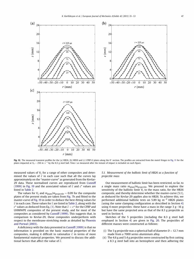
Fig. 12. The measured transient profiles for the (a) HB26, (b) HB50 and (c) CFRP-U plates along the 0� section. The profiles are extracted from the moiré fringes in Fig. 11 for theplates impacted at V0 ¼ 250 m s�1 by the 8.3 g steel ball. Time t as measured after the instant of impact is included on each figure.
K. Karthikeyan et al. / European Journal of Mechanics A/Solids 42 (2013) 35e53 47
measured values of VL for a range of other composites and deter-mined the values of bc in each case such that all the curves layapproximately on the “master-curve” as generated from the Kevlar-29 data. These normalised curves are reproduced from Cunniff(1999) in Fig. 19 and the associated values of bc and c* values arelisted in Table 2.
The values for VL and mplate/mprojectile ¼ 0.09 for the compositeplates of the present study are taken from Fig. 7b and fitted to themaster-curve of Fig. 19 in order to deduce the best-fitting values forbc in each case. These values for bc are listed in Table 2, alongwith thec* values as deduced from Eq. (1). Note that bc < c* for the CFRP andUHMWPE composites of the present study, and for most of thecomposites as considered by Cunniff (1999). This suggests that, incomparison to Kevlar-29, these composites underperform withrespect to the membrane-stretching mode as detailed by Phoenixand Porwal (2003).
A deficiency with the data presented in Cunniff (1999) is that noinformation is provided on the basic material properties of thecomposites, making it difficult to rationalize bc in terms of morefundamental material properties. We proceed to discuss the addi-tional factors that affect the value of bc.
5.1. Measurement of the ballistic limit of HB26 as a function ofprojectile mass
Our measurement of ballistic limit has been restricted, so far, toa single mass ratio mplate/mprojectile. We proceed to explore thesensitivity of the ballistic limit VL to the mass ratio, for the HB26composite, and thereby determine whether the master-curve (5.1),as deduced for Kevlar-29 applies also to HB26. To achieve this, weperformed additional ballistic tests on 5.89 kg m�2 HB26 plates(using the same clamping configuration as described in Section 4)using 4 more projectiles: these have a mass in the range 3 ge16 gbut have the same projected area as that of the 8.3 g projectile asused in Section 4.
Sketches of the 5 projectiles (including the 8.3 g steel ballemployed in Section 4) are given in Fig. 20. The projectiles ofdifferent masses were constructed as follows:
(i) The 3 g projectile was a spherical ball of diameter D¼ 12.7mmmade from a 7000 series aluminium alloy.
(ii) The 4.6 g and 5.4 g projectiles were constructed by first cuttinga 8.3 g steel ball into an hemisphere and then adhering the

Fig. 13. The time evolution of the hinge location rhinge in the (a) HB26, (b) HB50 and (c) CFRP-U plates impacted by the 8.3 g steel ball at impact velocities indicated in each figure.Data is shown along both 0� and 45� sections marked in Fig. 11 with time t as measured after the instant of impact.
K. Karthikeyan et al. / European Journal of Mechanics A/Solids 42 (2013) 35e5348
hemisphere to a Nylon backing cylinder, of identical diameterD ¼ 12.7 mm and length 9.8 mm, see Fig. 20. While the 5.4 gprojectile was adhered to a solid Nylon cylinder, the 4.6 gprojectile weight was achieved by hollowing out the Nyloncylinder to reduce the overall weight of the projectile from5.4 g to 4.6 g.
(iii) The 16 g projectile was constructed by adhering the steelhemisphere to a steel cylinder of diameter D ¼ 12.7 mm andlength 12.5 mm, as described in (ii)
The measured values of VL for the HB26 plate impacted by thefive projectiles of different masses have been added to Fig. 19 withthe choice of bc ¼ 672 m s�1 (the same value as that obtained inthe previous section of the paper for HB26). The measurementsnormalised in this manner lie on the Cunniff (1999) master-curve.
5.2. Relation of bc to composite properties
Phoenix and Porwal (2003) analysed the problem of an elasticmembrane impacted by a projectile. Using this analysis theycalculated the maximum strain (which occurs immediately underthe projectile) as a function of impact velocity. By setting this strainequal to the uniaxial failure strain Phoenix and Porwal (2003)
demonstrated that the ballistic limit of the membrane follows arelation of the form, Eq. (2), but with bc given by c* as defined in Eq.(1) for the effective properties of the laminate rather than for thefibre: Phoenix and Porwal (2003) took sf, 3f, Ef and rf to be theeffective values of the membrane material. For the sake of clarity,we denote this velocity as ~c. Thus, ~c for the HB26 composite can becalculated using the measured laminate properties reported inSection 2. With sf ¼ 768MPa, 3f ¼ 2%, Ef h sf/ 3f and rf ¼ 970 kg m�3,the velocity bc ¼ 391 m s�1. This is significantly less than the valueof the scaling velocity bc ¼ 672 m s�1 required to collapse theHB26 ballistic data onto the Cunniff (1999) master-curve; seeTable 2. We note that material strain rate effects cannot rationalisethis discrepancy as the measurements of Russell et al. (2013) haveshown that the tensile response of SK76 Dyneema� fibres in theHB26 composite is strain rate insensitive over the relevant range of100 s�1e103 s�1. We conclude that the Cunniff/Phoenix parametersare insufficient to characterise the ballistic performance of theHB26 composite.
5.3. Cunniff/Phoenix analysis deficiencies
The experimental data presented in this study indicates keydrawbacks in using ~c based on the effective laminate properties to

Fig. 14. X-ray images along the diametrical section of the (a) HB26, (b) HB50 and (c) CFRP-U plates impacted by the 8.3 g steel ball at selected impact velocities V0. Images are shownfor V0 both below and above the ballistic limit.
3 Recall that the shear strength as measured in this inter-laminar shear test isapproximately half the initial tensile yield strength of composites in the �45�
orientation.
K. Karthikeyan et al. / European Journal of Mechanics A/Solids 42 (2013) 35e53 49
predict the ballistic limit of composite plates. This is clearly seen inTable 2 where we note that the ~c values are not equal to bc for any ofthe composite systems employed in this study, i.e. ~c does noteffectively characterise the ballistic performance of these com-posites. We briefly discuss some underlying reasons for thisdiscrepancy.
The ballistic limit as defined by ~c is independent of the shearstiffness and strength of the laminates. In the results presented inSection 4, we have demonstrated that VL is strongly dependent onthe shear properties. The ballistic limits VL for the CFRP and UHMPE
plates impacted by the 8.3 g steel balls are plotted in Fig. 21 as afunction of the measured shear strength sY of the composites (inFig. 21 sY is defined to be equal to half the uniaxial tensile strength,sy of the composite in the �45� orientation3 for an applied strainrate of 10�3 s�1; see Fig. 3). The CFRP-C and CFRP-U composites

Fig. 15. (a) X-ray images along the diametrical section of CFRP-C plates impacted by the 8.3 g steel ball at selected impact velocities V0. Images are shown for V0 both below andabove the ballistic limit. (b) A high resolution image of the V0 ¼ 69 m s�1 CFRP-C case from (a) showing the formation of a cone crack under the projectile.
K. Karthikeyan et al. / European Journal of Mechanics A/Solids 42 (2013) 35e5350
have identical values of sf, 3f, Ef and rf as both plates have the samefibre type and volume fracture; the measured values of these pa-rameters (Fig. 3) gives ~c ¼ 300 m s�1for both the CFRP-U andCFRP-C plates. Similarly, the HB26 and HB50 UHMWPE plates haveidentical values of these material properties, to give~c ¼ 391 m s�1. It is clear from Fig. 21 that VL increases sharplywith decreasing sY for both the CFRP and UHMWPE plates eventhough ~c remains fixed in both cases. It is insufficient to use just ~c tocharacterise the ballistic performance of these plates: ~c is inde-pendent of sYwhile the ballistic limit depends strongly on the shearstrength of the composites.
The origins of this discrepancy can be understood by re-examining the Phoenix and Porwal (2003) rationalisation of theCunniff (1999) observations. Phoenix and Porwal (2003) presentedan elegant analysis in an attempt to rationalise the Cunniff (1999)observation that the ballistic limit of fibre composite plates scaleslinearly with bc. Phoenix and Porwal (2003) predicted that VL scaleslinearly with ~c based on the assumption that failure occurs in amembrane-like mode under the projectile. This failure mode is abinary event with all plies of the composite plate failing at animpact velocity VL. Such a membrane type failure mode is notobserved in any of the composite plates tested here: while a brittle
Fig. 16. X-ray images along the diametrical section of stainless steel plates impacted by the 8above the ballistic limit.
cone-like fracture mode involving negligible plate deflections oc-curs for the CFRP-C plates (Fig. 15), the UHMWPE and CFRP-U platesfail in a progressive manner (Fig. 14) with an increasing number ofplies failing with increasing impact velocity until all plies fail at VL,as discussed in Section 4.1.
We finally note that the parameter introduced by Cunniff (1999),labelled bc here, can be treated as an independent material propertythat captures the dependence of VL on the ratios of the areal massesof the plate and projectile. Thus, a single ballistic test to calibrate bcwill enable the prediction of the ballistic limit of the fibre com-posite plates over a range of projectile/plate masses using themaster curve presented in Fig. 19. The dependence of bc on morefundamental material properties such as shear strength, fibrestrength, etc. remains a key research challenge in understandingthe ballistic performance of fibre composite systems.
6. Concluding remarks
The impact and ballistic performance of CFRP and Ultra HighMolecular Weight Polyethylene (UHMWPE) clamped laminateplates of equal areal mass wasmeasured and compared with that of304 stainless steel plates. Two grades of UHMWPE and of CFRP
.3 g steel ball at selected impact velocities V0. Images are shown for V0 both below and
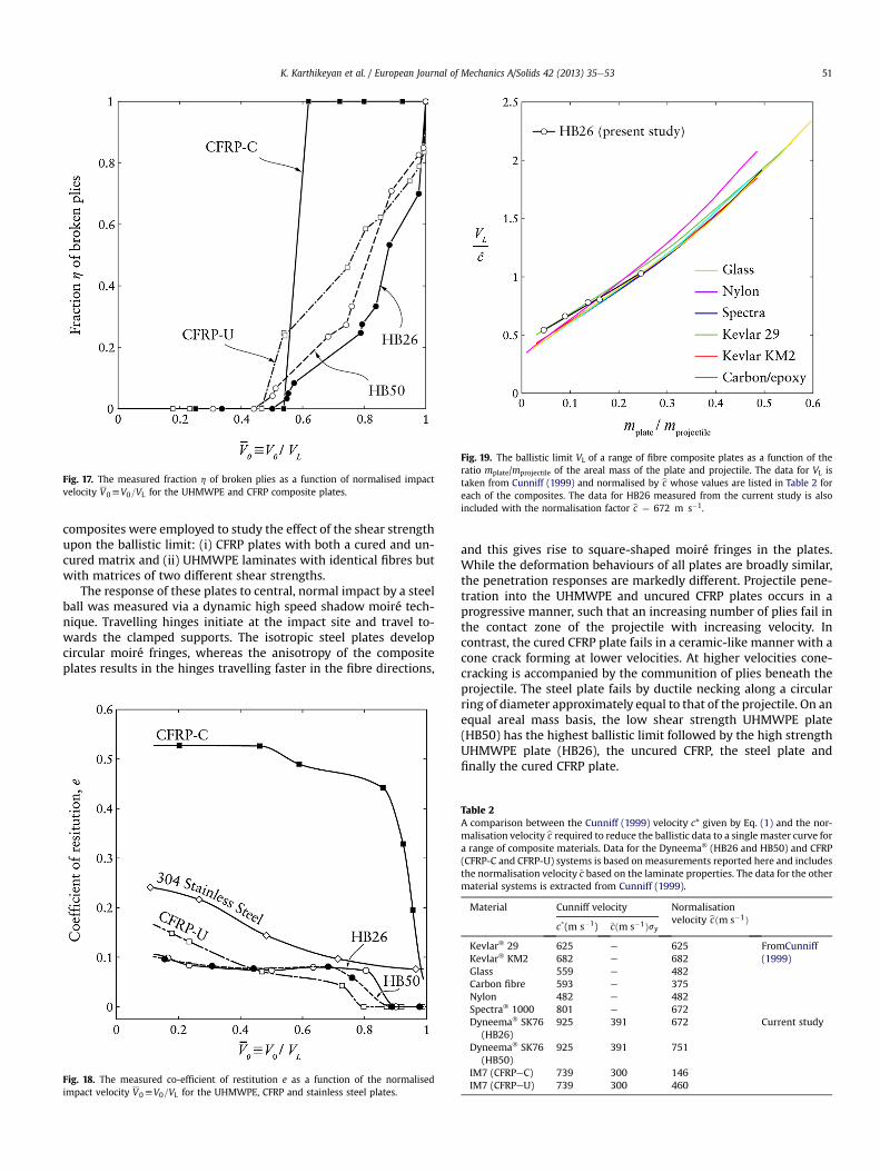
Fig. 19. The ballistic limit VL of a range of fibre composite plates as a function of theratio mplate/mprojectile of the areal mass of the plate and projectile. The data for VL istaken from Cunniff (1999) and normalised by bc whose values are listed in Table 2 foreach of the composites. The data for HB26 measured from the current study is alsoincluded with the normalisation factor bc ¼ 672 m s�1.
Fig. 17. The measured fraction h of broken plies as a function of normalised impactvelocity V0hV0=VL for the UHMWPE and CFRP composite plates.
K. Karthikeyan et al. / European Journal of Mechanics A/Solids 42 (2013) 35e53 51
composites were employed to study the effect of the shear strengthupon the ballistic limit: (i) CFRP plates with both a cured and un-cured matrix and (ii) UHMWPE laminates with identical fibres butwith matrices of two different shear strengths.
The response of these plates to central, normal impact by a steelball was measured via a dynamic high speed shadow moiré tech-nique. Travelling hinges initiate at the impact site and travel to-wards the clamped supports. The isotropic steel plates developcircular moiré fringes, whereas the anisotropy of the compositeplates results in the hinges travelling faster in the fibre directions,
Fig. 18. The measured co-efficient of restitution e as a function of the normalisedimpact velocity V0hV0=VL for the UHMWPE, CFRP and stainless steel plates.
and this gives rise to square-shaped moiré fringes in the plates.While the deformation behaviours of all plates are broadly similar,the penetration responses are markedly different. Projectile pene-tration into the UHMWPE and uncured CFRP plates occurs in aprogressive manner, such that an increasing number of plies fail inthe contact zone of the projectile with increasing velocity. Incontrast, the cured CFRP plate fails in a ceramic-like manner with acone crack forming at lower velocities. At higher velocities cone-cracking is accompanied by the communition of plies beneath theprojectile. The steel plate fails by ductile necking along a circularring of diameter approximately equal to that of the projectile. On anequal areal mass basis, the low shear strength UHMWPE plate(HB50) has the highest ballistic limit followed by the high strengthUHMWPE plate (HB26), the uncured CFRP, the steel plate andfinally the cured CFRP plate.
Table 2A comparison between the Cunniff (1999) velocity c* given by Eq. (1) and the nor-malisation velocity bc required to reduce the ballistic data to a single master curve fora range of composite materials. Data for the Dyneema� (HB26 and HB50) and CFRP(CFRP-C and CFRP-U) systems is based onmeasurements reported here and includesthe normalisation velocity ~c based on the laminate properties. The data for the othermaterial systems is extracted from Cunniff (1999).
Material Cunniff velocity Normalisationvelocity bcðm s�1Þ
c*(m s�1) ~cðm s�1ÞsyKevlar� 29 625 e 625 FromCunniff
(1999)Kevlar� KM2 682 e 682Glass 559 e 482Carbon fibre 593 e 375Nylon 482 e 482Spectra� 1000 801 e 672Dyneema� SK76
(HB26)925 391 672 Current study
Dyneema� SK76(HB50)
925 391 751
IM7 (CFRPeC) 739 300 146IM7 (CFRPeU) 739 300 460

Fig. 20. Sketches of the 5 projectiles of different masses but equal projected areas used to study the ballistic Cunniff-type scaling of the HB26 composite plates.
Fig. 21. The ballistic limit VL of the UHMWPE and CFRP composite plates as a functionof the shear strength sY. The designations of the each of the composites are indicated inthe figure.
K. Karthikeyan et al. / European Journal of Mechanics A/Solids 42 (2013) 35e5352
The scaling of the ballistic limit as a function of the projectilemass was measured for the UHMWPE plates of high shear strength.These measurements demonstrated that the ballistic data followeda Cunniff-type scaling. However, the Cunniff velocity required tonormalise the ballistic limit velocities was significantly higher thanthat estimated from the laminate properties. In fact, the data pre-sented here has clearly shown that the ballistic limit for both theCFRP and UHMWPE plate increased with decreasing shearstrength: this dependence cannot be captured by the Cunniffscaling as the Cunniff velocity is independent of the compositeshear strength. While this study has demonstrated the effect of thecomposite shear strength on the ballistic performance, no mecha-nistic models to explain this dependence has, as yet, been pro-posed. This remains a topic for future research.
Acknowledgements
This research was supported by the Office of Naval Research(ONR NICOP grant number N62909-12-1-7060) as part of a Multi-disciplinary University Research Initiative on “Cellular materialsconcepts for force protection”, Prime Award No. N00014-07-1-0764is gratefully acknowledged. The program manager was Dr DavidShifler. The authors also wish to thank DSM Dyneema for supplyingthe HB26 and HB50 laminate plates, and technical discussion
facilitating the experimental programme. Dyneema� is a trademarkof DSM. Dr B. P. Russell was supported by a Ministry of Defence/Royal Academy of Engineering Research Fellowship.
References
Benloulo, I.C., Rodríguez, J., Martínez, M.A., Gálvez, V.S., 1997. Dynamic tensile testingof aramid and polyethylene fiber composites. Int. J. Impact Eng. 19, 135e146.
Compton, B.G., Gamble, E.A., Deshpande, V.S., Zok, F.W., 2012. Damage developmentin an armor alumina impacted with ductile metal spheres. J. Mech. Mater.Struct. 7, 575e591.
Cunniff, P.M., 1999. Dimensionless Parameters for Optimization of Textile BasedBody Armor Systems, pp. 1303e1310. Proc. 18th Int. Symp. Ballist.
Daniel, I.M., Ishai, O., 2005. Engineering Mechanics of Composite Materials. OxfordUniversity Press, New York.
Dessain, B., Moulaert, O., Keunings, R., Bunsell, A.R., 1992. Solid phase changecontrolling the tensile and creep behaviour of gel-spun high-modulus poly-ethylene fibres. J. Mater. Sci. 27, 4515e4522.
Espinosa, H.D., Lee, S., Moldovan, N., 2006. A novel fluid-structure interactionexperiment to investigate deformation of structural elements subjected toimpulsive loading. Exp. Mech. 46, 805e904.
Frissen, R.T., 1996. Modelling the Ballistic Impact Behaviour of Polyethylene-Fibre-Reinforced Composites. PhD thesis. University of Technology, Eindhoven.
Govaert, L.E., Lemstra, P.J., 1992. Deformation behavior of oriented UHMW-PE fibers.Colloid Polym. Sci. 270, 455e464.
Govaert, L.E., Bastiaansen, C.W.M., Leblans, P.J.R., 1993. Stress-strain analysis oforiented polyethylene. Polymer 34, 534e540.
Greenhalgh, E.S., Bloodworth, V.M., Iannucci, L., Pope, D., 2013. Fractographic ob-servations on Dyneema� composites under ballistic impact. Composites Part A44, 51e62.
Grujicic, M., Arakere, G., He, T., Bell, W.C., Glomski, P.S., Cheeseman, B.A., 2009.Multi-scale ballistic material modeling of cross-plied compliant composites.Composites: Part B 40, 468e482.
Grujicic, M., Glomski, P.S., He, T., Arakere, G., Bell, W.C., Cheeseman, B.A., 2009a.Material modeling and ballistic-resistance analysis of Armor-grade compositesreinforced with high-performance fibers. J. Mater. Eng. Perform. 18, 1169e1182.
Hearle, J.W.S., 2001. High-Performance Fibres. Woodhead Publishing.Huang, W., Wang, Y., Xia, Y., 2004. Statistical dynamic tensile strength of UHMWPE-
fibers. Polym 45, 3729e3734.Iannucci, L., Pope, D., 2011. High velocity impact and armour design. Express
Polymer Lett. 5, 262e272.Jacobs, M., Heijnen, N., Bastiaansen, C., Lemstra, P.J., 2000. A novel, efficient route for
the crosslinking and creep improvement of high modulus and high strengthpolyethylene fibres. Macromol. Mater. Eng. 283, 120e125.
Karthikeyan, K., Russell, B.P., Fleck, N.A., O’Masta, M., Wadley, H.N.G.,Deshpande, V.S., 2013. The soft impact response of composite laminate beams.Int. J. Impact. Eng. 60, 24e36.
Koh, A.C.P., Shim, V.P.W., Tan, V.B.C., 2010. Dynamic behaviour of UHMWPE yarnsand addressing impedance mismatch effects of specimen clamps. Int. J. Impact.Eng. 37 (3), 324e343.
Koh, C.P., Shim, V.P.W., Tan, V.B.C., Tan, B.L., 2008. Response of a high-strengthflexible laminate to dynamic tension. Int. J. Impact Eng. 35, 559e568.
Kromm, F.X., Lorriot, T., Coutand, B., Harry, R., Quenisset, J.M., 2003. Tensile and creepproperties of ultra high molecular weight PE fibres. Polym. Test. 22, 463e470.
Lawn, B.R., 1998. Indentation of ceramics with spheres: a century after hertz. J. Am.Ceram. Soc. 81, 1977e1994.
Lee, S., 2005. Dynamic Failure of Blast-Resistant Structures Subjected to ImpulsiveLoading. PhD thesis. Northwestern University.
Liu, G., Thouless, M.D., Deshpande, V.S., Fleck, N.A., 2013. Collapse mechanisms of aUHMWPE laminated beam. Int. J. Solids Struct. (submitted for publication).
Peijs, A.A.J.M., Catsman, P., Govaert, L.E., Lemstra, P.J., 1990. Hybrid composites basedon polyethylene and carbon fibres Part 2: influence of composition and adhesionlevel of polyethylene fibres on mechanical properties. Composites 21, 513e521.
Persson, J., Breder, K., Rowcliffe, D.J., 1993. Loading rate effects during indentationand impact on glass with small spheres. J. Mater. Sci. 28, 6484e6489.

K. Karthikeyan et al. / European Journal of Mechanics A/Solids 42 (2013) 35e53 53
Phoenix, S.L., Porwal, P.K., 2003. A new membrane model for the ballistic impactresponse and V50 performance of multi-ply fibrous systems. Int. J. Solids Struct.40, 6723e6765.
Russell, B.P., Karthikeyan, K., Deshpande, V.S., Fleck, N.A., 2013. The high strain rateresponse of Ultra High Molecular-weight Polyethylene: from fibre to laminate.Int. J. Impact. Eng. 60, 1e9.
Smith, J.C., McCrackin, F.L., Schiefer, H.F., 1958. Stress-Strain relationships in yarnssubjected to rapid impact loading-Part V: wave propagation in long textileyarns impacted transversely. Text. Res. J. 28, 288e302.
Smith, P., Lemstra, P., 1980. Ultra-high-strength polyethylene filaments by solutionspinning/drawing. J. Mater. Sci. 15, 505e514.
Smith, P., Lemstra, P.J., Kalb, B., Pennings, A.J., 1979. Ultrahigh-strength polyethylenefilaments by solution spinning and hot drawing. Polym. Bull. 1, 733e736.
Vlasblom, M.P., Dingenen, J.L.J.V., 2009. The manufacture, properties and applica-tions of high strength, high modulus polyethylene fibers. In: Bunsell, A. (Ed.),
Handbook of Tensile Properties of Textile and Technical Fibres. WoodheadPublishing Series in Textiles, pp. 437e485.
Wang, L., 2007. Foundation of Stress Waves. Elsevier.Wei, X., Tran, P., Vaucorbeil, A.D., Ramaswamy, R.B., Latourte, F., Espinosa, H.D.,
2013a. Three-dimensional numerical modeling of composite panels subjectedto underwater blast. J. Mech. Phys. Solids 61 (6), 1319e1336.
Wei, X., Vaucorbeil, A.D., Tran, P., Espinosa, H.D., 2013b. A new rate-dependentunidirectional composite model e application to panels subjected to under-water blast. J. Mech. Phys. Solids 61 (6), 1305e1318.
Wilding, M.A., Ward, I.M., 1978. Tensile creep and recovery in ultra-high moduluslinear polyethylenes. Polymer 19, 969e976.
Wilding, M.A., Ward, I.M., 1981. Creep and recovery of ultra high modulus poly-ethylene. Polym 22, 870e876.
Wilding, M.A., Ward, I.M., 1984. Creep and stress-relaxation in ultra-high moduluslinear polyethylene. J. Mater. Sci. 19, 629e636.