the effect of reduction atmosphere on the lagao3...
TRANSCRIPT

1
The effect of reduction atmosphere on the LaGaO3-based solid oxide fuel cell
Jae Yeon Yi and Gyeong Man Choi*Department of Materials Science and Engineering, Pohang University of Science and Technology, San
31, Hyoja-dong, Pohang, 790-784, South Korea* Corresponding author
AbstractChemical stability of La0.9Sr0.1Ga0.8Mg0.2O3 (LSGM) as an electrolyte for solid oxide
fuel cells (SOFCs) was investigated during the electrochemical measurement. At low oxygen-partial pressure (0.003 atm), the LSGM electrolyte partly decomposed due to the developmentof high overpotential, and thus the induced reduction atmosphere near cathode. The morphologyof LSGM grain near cathode changed due to the formation of new phases. The maindecomposition phases were La2O3, La(OH)3, and LaSrGaO4. The polarization conductanceincreased due to the microstructural change in LSM and thus the increase in the specific area ofthe LSM electrode.
Keywords : SOFC(E), LaGaO3, Electrical conductivity(C), Decomposition, Chemical stability
1. IntroductionThe solid oxide fuel cells are under development for the generation of electricity with
little environmental pollution. Since lowering the operating temperature has many advantages,such as the broad choice of cheap interconnect materials and the long-term stability of cellcomponents, much efforts thus have been concentrated on finding an electrolyte material withhigher ion conductivity than YSZ (Yttria Stabilized Zirconia) that is commercially used as anelectrolyte for SOFCs [1-3].
An electrolyte for SOFCs is required not only to have high oxygen-ion conductivitybut also to have a high stability under severe operating conditions, such as high temperature andlarge oxygen-partial pressure (Po2) gradient for a long time. Previous studies [4-7] showed thedegradation of LSGM electrolyte during sintering at high temperature or operating in reducingatmosphere. LSGM easily decomposes, especially when sintered at temperature greater than1600 oC, due to the tendency of gallium (III) oxide reduction to gallium (I) oxide [4]. Yamaji etal. [5-7] examined the chemical stability of LSGM in reducing atmosphere. They showed thatthe migration of Si and Al from Pyrex sealant and Pt from electrode into the surface of LSGMelectrolyte gives rise to the depletion of Ga from LSGM electrolyte [5]. The reaction of Ga2O3with H2 in very low Po2 resulted in the formation of Ga2O and H2O (vaporization of Ga) [6].Doping of lanthanum gallate with Sr and the existence of Pt enhanced the depletion of Ga fromthe electrolyte in the reducing atmosphere [7].
Examination of Po2 dependence of overpotential is one method to determine thereduction mechanism of LSGM. As Po2 decreases, the cathodic overpotential increases withapplied current. High cathodic overpotential tends to reduce the electrolyte. However, the effectof high potential on the cathode and electrolyte due to the applied current is not yet clear forLSGM electrolyte-based fuel cells. In this study, the change in cathode performance andelectrolyte properties under high overpotential condition was examined.
2. ExperimentalStoichiometric amount of La2O3 (99.99%, Strem Chemicals, USA), SrCO3 (99.9%,
High Purity Chemicals, Japan), and Mn2O3 (99.9%, High Purity Chemicals) powders weremixed to prepare LSM (La0.9Sr0.1MnO3) electrode, and La2O3, SrCO3, Ga2O3 (99.9%, HighPurity Chemicals), and MgO (99.9%, High Purity Chemicals) powders for LSGM electrolyte.

2
The powder mixtures were ball-milled with zirconia balls in distilled water for 12 h, andcalcined at 1200 oC for 6 h. The calcined LSGM powder was formed into disc-shape by diepressing, followed by cold isostatic pressing at 200 Mpa and sintering at 1500 oC for 6 h in airwith the heating/cooling rate of 3 OC/min. Sintered LSGM pellet was sliced into thin disks of ~500µm.
The calcined LSM powders was screen-printed on LSGM electrolyte and heat treatedor sintered at 1300 oC in air for 2 h. Three-electrode configuration cells were fabricated; theworking electrode is a cathode under investigation and the counter and the reference electrodesare platinum on the opposite side of the working electrode. The cell was heated for 1 h at 1000oC after Pt pasting (Engelhard No. 6926, USA). Pt mesh (Aldrich 52 mesh, USA), as a currentcollector, was bonded at 1000 oC for 1 h to three electrodes.
The ohmic- and the over-potential values were measured by using a currentinterruption device (Doosung Induction, DSI-10, Korea), a current source (Solartron, SI 1287,UK) and digitizing oscilloscope (Tektronix, TDS 3032, USA). The electrochemicalmeasurement was performed between 800 and 900 oC in Po2 between 1 and 0.003. The cathodicoverpotential changed with time and reached its steady state value within 10 min at high Po2,and within 1 h at Po2 = 0.003 atm. Microstructure was observed by a field-emission scanningelectron microscope (JEOL, model 6330F, Japan).
3. Results and DiscussionThe cathodic overpotential of LSM electrode as a function of current density is shown
in Fig. 1. The cathodic overpotential at 1 atm of Po2 (1 atm (before)) increased slowly as thecurrent density increased. The curves obtained at Po2 greater than 0.015 atm showed the similartrend as the 1 atm curve. However, at Po2 = 0.003 atm, the cathodic overpotential increasedsharply with current density. Such an increase is often due to a diffusion limiting process.Oxygen cannot be supplied fast enough from cathode to electrolyte with increasing currentdensity. The cathodic overpotential value at 100 mA/cm2 of current density was ∼ 1.85 V.Hereafter, we refer the measurement under 1.85 V at 800 oC, Po2 = 0.003 atm as the low Po2measurement. The cathodic overpotential value was measured again at 1 atm after the low Po2measurement and it (1 atm (after)) was smaller than the initial value (1 atm (before)). Thedecrease in overpotential after the low Po2 measurement needs explanation. Gharbage et al. [8]reported that oxygen vacancies were created in the LSM electrode at high polarization, and thecathodic reaction was progressively delocalized over the whole surface of the electrode. Duringthe low Po2 measurement, specimen was maintained under high overpotential (∼1.85 V) andthus oxygen vacancies may have been created in LSM electrode. The Po2 equilibrated withexternal electromotive force (e.m.f.) follows the Nernst equation:
'
2
"
2ln4
...O
O
PP
FRTfme −= (1)
where R, T, '
2OP , and "
2OP are the gas constant, the absolute temperature, the reference Po2, andthe equilibrated Po2. Since the reference Po2 was 0.003 atm and the emf value was 1.85 V, the
"
2OP may be as low as 3.65x10-36 atm at 800 oC. Such a highly reducing Po2 enhances theformation of oxygen vacancies in LSM electrode.
The effect of reduction potential on the cathode performance was examined. Fig. 2shows the temperature dependence of polarization conductance (Gp) at 40 mA/cm2 of currentdensity. The polarization conductance was defined as:
JR
GC
PP
η==1 (2)
where RP is the polarization resistance, ηc is the cathodic overpotential and J is the current den-sity.
3
The polarization conductance at 1 atm increased after the low Po2 measurement at0.003 atm. The activation energy of GP of LSM electrode at 1 atm is similar before and after thelow Po2 measurement (0.73 ∼ 0.75 eV). The reported activation energy values of GP are knownto be varying depending on the combination of electrode and electrolyte. For YSZ electrolyte,La0,7Sr0.3MnO3 and La0.7Sr0.3CoO3 electrodes showed 1.87 and 2.28 eV [9], respectively, andLa0.8Sr0.2MnO3-YSZ composite electrode showed 1.49 eV [10]. La0.6Sr0.4CoO3 andLa0.9Sr0.1Ga0.5Ni0.5O3 electrodes on LSGM electrolyte showed 0.96 and 1.816 eV [11].La0.6Sr0.4Co0.98Ni0.02O3, La0.6Sr0.4CoO3 and Pt electrodes on (CeO2)0.9(CaO)0.1 electrolyte showed0.5, 0.63 and 1.13 eV, respectively [12]. Generally, the electrodes having the charge transferreaction as the rate-determining step of oxygen reduction show high activation energy of GP.Thus no electrode composition or oxygen-reduction mechanism has been changed after the lowPo2 measurement.
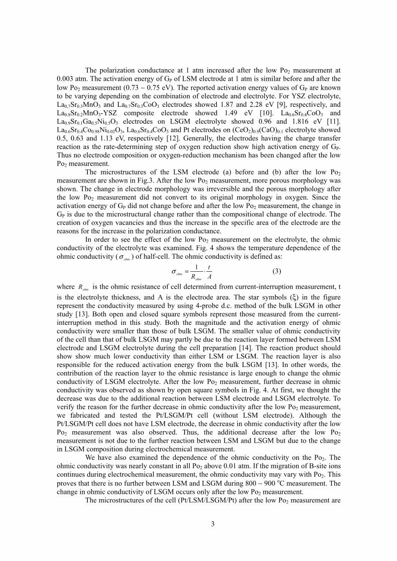
The microstructures of the LSM electrode (a) before and (b) after the low Po2measurement are shown in Fig.3. After the low Po2 measurement, more porous morphology wasshown. The change in electrode morphology was irreversible and the porous morphology afterthe low Po2 measurement did not convert to its original morphology in oxygen. Since theactivation energy of GP did not change before and after the low Po2 measurement, the change inGP is due to the microstructural change rather than the compositional change of electrode. Thecreation of oxygen vacancies and thus the increase in the specific area of the electrode are thereasons for the increase in the polarization conductance.
In order to see the effect of the low Po2 measurement on the electrolyte, the ohmicconductivity of the electrolyte was examined. Fig. 4 shows the temperature dependence of theohmic conductivity ( ohmσ ) of half-cell. The ohmic conductivity is defined as:
At
Rohmohm ⋅= 1σ (3)
where ohmR is the ohmic resistance of cell determined from current-interruption measurement, tis the electrolyte thickness, and A is the electrode area. The star symbols (ξ) in the figurerepresent the conductivity measured by using 4-probe d.c. method of the bulk LSGM in otherstudy [13]. Both open and closed square symbols represent those measured from the current-interruption method in this study. Both the magnitude and the activation energy of ohmicconductivity were smaller than those of bulk LSGM. The smaller value of ohmic conductivityof the cell than that of bulk LSGM may partly be due to the reaction layer formed between LSMelectrode and LSGM electrolyte during the cell preparation [14]. The reaction product shouldshow show much lower conductivity than either LSM or LSGM. The reaction layer is alsoresponsible for the reduced activation energy from the bulk LSGM [13]. In other words, thecontribution of the reaction layer to the ohmic resistance is large enough to change the ohmicconductivity of LSGM electrolyte. After the low Po2 measurement, further decrease in ohmicconductivity was observed as shown by open square symbols in Fig. 4. At first, we thought thedecrease was due to the additional reaction between LSM electrode and LSGM electrolyte. Toverify the reason for the further decrease in ohmic conductivity after the low Po2 measurement,we fabricated and tested the Pt/LSGM/Pt cell (without LSM electrode). Although thePt/LSGM/Pt cell does not have LSM electrode, the decrease in ohmic conductivity after the lowPo2 measurement was also observed. Thus, the additional decrease after the low Po2measurement is not due to the further reaction between LSM and LSGM but due to the changein LSGM composition during electrochemical measurement.
We have also examined the dependence of the ohmic conductivity on the Po2. Theohmic conductivity was nearly constant in all Po2 above 0.01 atm. If the migration of B-site ionscontinues during electrochemical measurement, the ohmic conductivity may vary with Po2. Thisproves that there is no further between LSM and LSGM during 800 ∼ 900 oC measurement. Thechange in ohmic conductivity of LSGM occurs only after the low Po2 measurement.
The microstructures of the cell (Pt/LSM/LSGM/Pt) after the low Po2 measurement are

4
shown in Fig. 5. The LSGM electrolyte near LSM cathode became porous and small grains areshown. In contrast, the original LSGM electrolyte (far right side of Fig. 6b) is dense and haslarge grains. This porous area was formed due to the decomposition of LSGM electrolyte.Approximately 100 µm away from LSM electrode, needle-shaped phases were newly formed.We named this area as a decomposition front in Fig. 6b. The decomposition front moves awayfrom the LSM/LSGM interface to the counter electrode (Pt) with time during the low Po2measurement. For the cells using either 0.4LSM-0.6LSGM composite (Pt/0.4LSM-0.6LSGM/LSGM/Pt) or Pt (Pt/LSGM/Pt) as a cathode, the same decomposition behavior (i. e.,porous decomposition layer and needle-shaped phase in decomposition front) was observed. Inall cells, decomposition of the LSGM electrolyte initiates near cathode/electrolyte interface. Thedecomposition front was found at ∼ 80 µm from the Pt cathode for the Pt/LSGM/Pt cell. For thiscell, the overpotential due to the applied current of 100mA/cm2 was 1.65 V. The closer location(∼ 80 µm) of the decomposition front from cathode for the Pt cathode than that (∼ 100 µm) forthe LSM cathode is reasonable considering the smaller potential for the Pt cathode (1.65V) thanthe LSM cathode (1.85V). As the overpotential increases, the reduction of cathode side becomemore severe and the wider decomposition layer is expected.
During the low Po2 measurement, the overpotential may be concentrated on thecathode/electrolyte interface due to the higher overpotential than the ohmic potential. Thereducing atmosphere as low as 3.65x10-36 atm can be developed at the interface forPt/LSM/LSGM/Pt cell. This reduction potential is possible if the oxygen flow is partiallyblocked. The reported decomposition Po2 for LSGM at 800 oC is ∼ 10-22 atm [5, 15]. Thus, weneed only ∼ 1.04V to obtain ∼10-22 atm with respect to the counter electrode potential. Althoughthe actual Po2 at the decomposition front is not clear due to the unknown potential distributionacross the cell, the Po2 at the decomposition front may be as low as 10-22 atm when the cathodeworks as a current limiting or an ion-blocking electrode.
To determine the phases formed in the decomposition layer, the Pt/LSGM/Pt cell wasmaintained at low Po2 (0.003 atm) at 800 oC, while supplying 100 mA/cm2 (∼ 1.65V ofoverpotential) for ∼10 h. The resultant cell was crushed and examined by X-ray diffraction. Inaddition to the original LSGM phase, La2O3, La(OH)3, and LaSrGaO4 were observed. It is notedthat white powder, observed on the Pt cathode surface, was identified as La2O3 and La(OH)3.These phases probably formed as a result of Ga evaporation on the cathode surface that wasexposed to the reducing atmosphere [6, 7]. LaSrGaO4 is a Sr-rich LaGaO3 phase. No Mg-excessphase was observed. Mg is probably contained in La2O3 or LaSrGaO4 as a solid-solutioncomponent [6].
4. ConclusionsThe cathodic overpotential of LSM/LSGM/Pt cell at low Po2 (0.003 atm) increased
sharply as the current density increased due possibly to the limited oxygen diffusion at thecathode. As a result of reduction, the polarization conductance increased due to the formation ofporous LSM cathode. However, the ohmic conductivity of the LSGM electrolyte decreasedsince LSGM electrolyte decomposed in reducing atmosphere. The decomposition layer formednear cathode was porous and had small grains. The needle-shaped phases were newly formed atthe decomposition front. The main decomposition phases of the LSGM electrolyte are La2O3,La(OH)3, and LaSrGaO4.
AcknowledgementsThis work was supported by the BK 21 Project. The authors thank to Doosung Induc-
tion Co. for the support of electronic switch that enables the current interruption measurement.
References[1] N. Q. Minh, J. Am. Ceram. Soc,. 76 (1993) 563.

5
[2] T. Ishihara, H. Matsuda, and Y. Takita, J. Am. Chem. Soc., 116 (1994) 3801.[3] E. D. Wachsman, P. Jayaweera, N. Jiang, D. M. Lowe, and B. G. Pound, J. Electrochem.Soc., 144 (1997) 233.[4] J. W. Stevenson, T. R. Armstrong, L. R. Pederson, J. Li, C. A. Lewinsohn, and S. Baskaran,Solid State Ionics, 113-115 (1998) 571.[5] K. Yamaji, T. Horita, M. Ishikawa, N. Sakai, and H. Yokokawa, ibid, 108 (1998) 415.[6] K. Yamaji, T. Horita, M. Ishikawa, N. Sakai, and H. Yokokawa, ibid, 121 (1999) 217.[7] K. Yamaji, H. Negishi, T. Horita, N. Sakai, and H. Yokokawa, ibid., 135 (2000) 389.[6] K. Tsuneyoshi, K. Mori, A. Sawata, J. Mizusaki, and H. Tagawa, ibid., 35 (1989) 263[7] M. J. L. Østergård and M. Mogensen, Electrochimica Act, 38 (1993) 2015[8] B. Garbage, T. Pannier, and A. Hammer, ibid., 141 (1994) 2118.[9] Y. Takeda, R. Kino, M. Noda, Y. Tumid, and O. Yamamoto, J. Electrochem. Soc., 134(1987) 2656.[10] E. P. Murray, T. Tsai, and S. A. Barnett, Solid State Ionics, 110 (1998), 235.[11] F. Lecarpentier, H. L. Tuller, and N. Long, J. Electroceramics, 5 (2000), 225.[12] T. Inoue, N. Seki, K. Eguchi, and H. Arai, J. Electrochem. Soc., 137 (1990), 2523.[13] J. Y. Yi and G. M. Choi, Solid State Ionics, 148 (2002) 557.[14] J. Y. Yi and G. M. Choi, J. Eur. Ceram. Soc., 24 (2004) 1359.[15] K. Huang, M. Feng, J. B. Goodenough, and M. Schmerling, J. Electrochem. Soc., 143(1996) 3630.

6
Figure Captions
Fig. 1. The cathodic overpotential of Pt/LSM/LSGM/Pt cell measured at 800 oC as a function ofcurrent density in Po2 =1 and 0.003 atm. It was measured in sequence of 1 atm (before), 0.003atm, and 1 atm (after).
Fig. 2. Temperature dependence of polarization conductance of LSM cathode measured at 40mA/cm2 of current density before and after the low Po2 measurement.
Fig. 3. Micrographs of LSM electrode (a) before and (b) after the low Po2 measurement.
Fig. 4. Temperature dependence of ohmic conductivity of LSGM electrolyte before and after thelow Po2 measurement.
Fig. 5. Micrographs of (a) decomposition layer and (b) decomposition front ofPt/LSM/LSGM/Pt cell after the low Po2 measurement.

7
0 20 40 60 80 1000
200
400
600
800
1000
1200
1400
1600
1800
2000
Fig. 1
1 atm (after)
1 atm (before)
0.003 atm
Po2At 800 oC
Cat
hodi
c ov
erpo
tent
ial (
η c/mV
)
Current density (mA/cm2)

8
0.84 0.86 0.88 0.90 0.92 0.94-1.0
-0.8
-0.6
-0.4
-0.2
0.0900 850 800
Ea= 0.75
Ea= 0.73
1 atm (before)
1 atm (after)
log
Gp(S
/cm
2 ) (at
40m
A/c
m2 )
1000/T (K-1)
Fig. 2
Temp (oC)
9
Fig.3
(a)
(b)

10
0.84 0.86 0.88 0.90 0.92 0.94
-1.6
-1.4
-1.2
-1.0
-0.8
Fig. 4
0.30 eV
0.22 eV
Ea = 0.64 eV
Bulk LSGM(0.21 atm)
1 atm (after)
1 atm (before)
log
σ ohm (S
/cm
)
1000/T (K-1)
900 850 800
Temp (oC)

11
Fig.5
Decompositionfront
Decomposi-tionlayer
LSM