the effect of a synthetic jet on the pressure distribution of a flat plate · 2014-12-11 ·...
TRANSCRIPT

1
Abstract The effect of a rectangular synthetic jet on the surface static pressure distribution on a flat plate in a zero freestream pressure gradient at Reynolds numbers in the range 8 x 10⁵ < Rec 1.8 x 10⁶, is investigated with a view to potential boundary layer flow control. The increment in surface static pressure distribution, relative to that of the undisturbed flat plate, is compared with that of conventional vane type vortex generator. Changes in pressure consistent with the formation of a longitudinal vortex are seen to be dependent on Reynolds number and slot yaw angle. The lateral influence of the synthetic jet efflux at axial stations(x,mm) between -200 < x < 300 is used to quantify the potential impact of the synthetic jet flowfield compared to that of a conventional vortex generator. Regions of +ve and –ve pressure changes are seen to be dependent on Reynolds number.
1 Design of Piezoelectric-driven Synthetic Jet Generator A piezoelectric diaphragm is a thin metal plate with a piezoelectric ceramic adhered to one face. A high frequency alternating voltage will cause the diaphragm to vibrate as a result of the difference of deformation ratio between the two materials. A piezoelectric diaphragm supplied by Murata Manufacturing Company (Product reference: 7BB-50M-1) is used to fabricate the Synthetic Jet Generator (SJG) used in this study. This particular diaphragm is designed for use in acoustic devices; it consists of a 50mm diameter nickel-plated brass disc with a 25mm diameter piezoelectric ceramic film on one face.[1]
Fig. 1. Expanded view of key SJG components
2 Experimental Arrangement The SJG used in this study is mounted beneath the surface of a flat plate, within a flush-fitting turntable, which can be rotated through 360 degrees to facilitate a change of SJG slot yaw angle (β) relative the free stream, see Figure 2. Slot yaw angle is known to be a significant factor in determining the strength of the longitudinal vortex that forms downstream of the slot as a result of the SJG efflux, see Kim [11]
Fig. 2. Plan elevation of turntable within the flat plate
and definition of slot yaw angle (β)
THE EFFECT OF A SYNTHETIC JET ON THE PRESSURE DISTRIBUTION OF A FLAT PLATE
Young-Hwan KIM*, K.P.Garry**
*Emirates Aviation University,UAE **Cranfield University, UK
Keywords: Synthetic Jet, Piezoelectric, Boundary layer, Vortex, Flow Control

Young-Hwan KIM, K.P.Garry
2
Figure 3 depicts the flat plate coordinate system, the origin of which is the centre of the SJG slot, located 25cm downstream of the flat plate leading edge. To aid data analysis, locations on the flat plate are non-dimensionalised using the slot width (H=0.5mm). Individual surface static pressure tappings are connected to a 48-port Scanivalve coupled to a Setra 239 differential pressure transducer pressure scanning system by means of flexible pneumatic tubes, shown in Figure 4. As these could not be located within the SJG assembly, the static pressure distribution in the region adjacent to the slot (-4cm < x < 3cm) cannot be measured - this area is referred to as a “blind area” in this study, see Figure 5.
Fig. 3. Flat plate coordinate system with SJG
Fig 4. SJG assembly mounted beneath the the flat plate
Fig 5. Schematic layout of SJG slot and adjacent rows of pressure tappings in the flat plate to illustrate the ‘blind area’
The surface static pressure distribution on the plate is measured using an array of six spanwise rows of 29 pressure tappings (3mm lateral spacing, centre to centre covering the lateral range -42mm < Y < +42mm. The pressure tapping rows cover axial locations in the range from X=50mm to X=300mm in 50mm increments. In addition, this matrix is supplemented by a streamwise row of 46 pressure tappings along the plate lateral centreline at 10mm increments. This row extends from x = -200mm (upstream of the SJG) to x = 300mm (downstream of the SJG). This arrangement is depicted schematically in Figure 6. Individual pressure tappings are fabricated from brass tube, which has 1.5mm external diameter and 0.9mm internal diameter. Each pressure port is sampled at a frequency (Fs) of 3 KHz for a sampling perod (Ts) of 3 seconds. A 3 second settling period is allowed before each measurement.
Fig. 6. Static pressure tapping arrangement
2.1 Vortex Generator A conventional vane type vortex generator (VG) was mounted on the plate at the same location as the SJG to facilitate pressure data for

3
THE EFFECT OF A SYNTHETIC JET ON THE PRESSURE DISTRIBUTION OF A FLAT PLATE
comparison purposes. The VG has a cropped delta planform with a chord (L) of 35mm – the same as that of the SJG slot length. The VG height is 5mm, equivalent to 152% of the maximum local boundary layer thickness (which was measured for the conditions U=8.53m/s, Rex=8.17×10⁵). The VG was installed over the SJG slot with an inclination (β) of 20 degrees to the free stream, the same as the optimum slot yaw angle for vortex generation. Figure 7 illustrates the design and installation of VG.
Fig. 7. Conventional vane type vortex generator
3 Discussion of Results The SJG is excited at a fixed acoustic resonance frequency (F1) of 1.5 KHz, which results in a mean jet velocity of 11.05 m/s. Because the mean synthetic jet velocity is constant, the jet momentum coefficient (Cµ) can be varied only be the changing the freestream velocity (U)
Synthetic Jet velocities @ resonance frequency Max Min RMS Mean
56.10 m/s 2.15 m/s 18.14 m/s 11.05 m/s The pressure coefficient (Cp) and pressure coefficient difference (ΔCp) are defined as the followings. The freestream data measured using a Pitot-static tube above the flat plate.
Cp = (p - p∞) / q∞ (1)
ΔCp = Cp_on - Cp_off (2)
Where, p: Local static pressure p: Freestream static pressure q: Freestream dynamic pressure : Freestream density U : Freestream velocity
onpC _ : Cp with SJG-On or with VG
offpC _ : Cp with SJG-Off or without VG
3.1 Spanwise static pressure distribution around the vortex core An example of the spanwise pressure increment distribution in a plane at x = 50mm as a result of the SJG is shown in Figure 8. This condition corresponds to a free stream velocity of U=8.53m/s and the variation of pressure coefficient increment (SJG on – SJG off) ΔCp, is similar to that seen as a result of using a conventional VG in a study by Mahalingam et al.[2]. Note that VR corresponds to the jet “Velocity Ratio” between mean synthetic jet velocity and freestream velocity. The core of the vortex created by the vane type VG, is located near the suction peak. The location of the core is approximated by the two vertical broken lines in Figure 8. The direction of rotation is considered to be counter-clockwise when viewed from downstream. The spanwise distribution ΔCp produced by a synthetic jet is similar to that of the vane type vortex generator. The suction peak appears at nominally Y/H=6 and the pressure distribution suggests a counter-clockwise rotation. At this condition (Rex=1.75×10⁵), the SJG produces a greater suction and pressure increment peak than that of the vane type vortex generator. According to the study of Zhang et al.[3], the streamwise vortex creates regions of local upwash and downwash within the boundary layer, the later responsible for momentum transfer which results in a “thining effect” on the boundary layer that enhances its ability to resist flow separation. Given that both the SJG (β=20°) and the vane type VG (β=20°) exhibit surface static pressure increments consistent with the formation of counter-clockwise rotating vortex structure, the SJG can be considered as a potential alternative to a conventional VG for flow control.

Young-Hwan KIM, K.P.Garry
4
Fig. 8. Vortex structure interpretation by Cp distribution
( Cµ=5.99×10⁻⁴, VR=1.30, X=50mm, Rex=1.75×10⁵) Figure 9 is a schematic of a possible synthetic jet slot arrangement on practical aerodynamic surfaces. An SJG array with same slot orientation will result in a row of vortices with the same rotation sign. However, an arrangement of synthetic jet slots with alternating slot yaw angles will result in vortices with different rotation directions. This concept is routinely used for practical flow control applications.
Fig. 9. Proposed arrangement of synthetic jet slot arrangement for practical application
3.2 Data repeatability The repeatability of the pressure increment distribution data (Cp) is investigated in view of the fact that the corresponding pressures at the Reynolds numbers (Rex) considered are very low and measurement uncertainty may be important. The degree of uncertainty is expressed by the error bars in Figure 10. Each data point is based on the mean of three measurements which are taken at the same test conditions. The error bars correspond to the standard deviation (σ) around the mean ΔCp. Whilst it can be seen that there is greater uncertainty at the lower Reynolds number (high-VR and high-Cµ), it is clear that the
measurement repeatability is such as to suggest that the pressure increments measured are the result of a characteristic flow phenomenon.
-50 0 50Y/H
-0.05
-0.04
-0.03
-0.02
-0.01
0
0.01
0.02
0.03
0.04
0.05
SJ (20 deg)
Cp
Pressure peak
Suction peak
(a) Synthetic jet
-50 0 50Y/H
-0.05
-0.04
-0.03
-0.02
-0.01
0
0.01
0.02
0.03
0.04
0.05
VG (20 deg)
Cp
Suction peak
Pressure peak
(b) Vortex generator
Fig. 10. The repeatability of Cp due to synthetic jet and vortex generator (X=50mm, β=20°, U=8.53m/s,
Cµ=5.99×10⁻⁴, VR=1.30, Rex=1.75×10⁵)
3.3 Effect of streamwise distance The development of the vortical flow structure downstream of both the synthetic jet and vane VG is investigated by considering the lateral pressure distribution at different axial locations within the zero pressure gradient boundary layer on the flat plate. The lateral displacement of the vortex is detected in each case, Figure 11 shows that the suction region moves in the +ve Y direction with increasing x and reduces in magnitude. This is assumed to relate to the lateral displacement of the vortex core and either its breakdown or increased vertical displacement from the plate surface.

5
THE EFFECT OF A SYNTHETIC JET ON THE PRESSURE DISTRIBUTION OF A FLAT PLATE
-50 0 50Y/H
-0.05
-0.04
-0.03
-0.02
-0.01
0
0.01
0.02
0.03
0.04
0.05
00 deg20 degVGRef
Cp
(a) X=50mm, Rex=3.32×10⁵
-50 0 50Y/H
-0.05
-0.04
-0.03
-0.02
-0.01
0
0.01
0.02
0.03
0.04
0.05
00 deg20 degVGRef
Cp
(b) X=100mm, Rex=3.87×10⁵
-50 0 50Y/H
-0.05
-0.04
-0.03
-0.02
-0.01
0
0.01
0.02
0.03
0.04
0.05
00 deg20 degVGRef
Cp
(c) X=150mm, Rex=4.43×10⁵
-50 0 50Y/H
-0.05
-0.04
-0.03
-0.02
-0.01
0
0.01
0.02
0.03
0.04
0.05
00 deg20 degVGRef
Cp
(d) X=200mm, Rex=4.98×10⁵
-50 0 50Y/H
-0.05
-0.04
-0.03
-0.02
-0.01
0
0.01
0.02
0.03
0.04
0.05
00 deg20 degVGRef
Cp
(e) X=250mm, Rex=5.53×10⁵
-50 0 50Y/H
-0.05
-0.04
-0.03
-0.02
-0.01
0
0.01
0.02
0.03
0.04
0.05
00 deg20 degVGRef
Cp
(f) X=300mm, Rex=6.09×10⁵
Fig. 11. Spanwise pressure distributions (U=16.18 m/s, C=1.6710-4, VR=0.68)
Changes in surface static pressure coefficient caused by the synthetic jet and the VG are depicted as a surface contours in Figures 12 and 13 respectively. As can be seen in Figure 12(a), that the effect of a synthetic jet with slot angle, β=0 does not result in a significant Cp, and its influence is almost imperceptible at X=100mm. By increasing the slot yaw angle to β=20 the synthetic jet creates a higher Cp, see Fig.12(b). Although, its effectiveness is still diminished with increasing (X), up to X=300mm, as expected, the vane type vortex generator (VG) was shown to cause more significant pressure changes. The areas of reduced pressure caused by the vane type vortex generator are not in line with freestream direction, which is assumed to be due to the lateral movement of the vortex core.

Young-Hwan KIM, K.P.Garry
6
-0.02
0
0.02
50
100
150
200
250
300
X (mm)
-50
0
50
Y/H
XY
Z0.01172840.008813790.005899160.002984546.9921E-05
-0.0028447-0.00575932-0.00867394-0.0115886-0.0145032-0.0174178-0.0203324-0.0232471-0.0261617-0.0290763
Cp
(a) β=0
-0.02
0
0.02
50
100
150
200
250
300
X (mm)
-50
0
50
Y/H
XY
Z0.01172840.008813790.005899160.002984546.9921E-05
-0.0028447-0.00575932-0.00867394-0.0115886-0.0145032-0.0174178-0.0203324-0.0232471-0.0261617-0.0290763
Cp
(b) β=20
Fig. 12. The effect of synthetic jet to downstream flowfield (U=16.18 m/s, VR=0.68, C=1.6710-4, Rec=1.55×10⁶, zero
pressure gradient)
-0.02
0
0.02
50
100
150
200
250
300
X (mm)
-50
0
50
Y/H
XY
Z0.01172840.008813790.005899160.002984546.9921E-05
-0.0028447-0.00575932-0.00867394-0.0115886-0.0145032-0.0174178-0.0203324-0.0232471-0.0261617-0.0290763
Cp
Fig. 13. The effect of vane type vortex generator (VG) to downstream flowfield (U=16.18 m/s, Rec=1.55×10⁶, β=20, zero pressure gradient)
3.4 Streamwise pressure change distribution in a zero freestream pressure gradient
A streamwise Cp distribution survey on the zero pressure gradient flat plate was carried out using datya from the single row of axial tappings (recognizing the blind area, x = -4cm ~ +3cm). As can be seen in Figure 14, the synthetic jet affects both the flowfield both downstream and upstream of the slot.
-20 -15 -10 -5 0 5 10 15 20 25 30X (cm)
-0.05
-0.04
-0.03
-0.02
-0.01
0
0.01
0.02
0.03
0.04
0.05
C = 5.99 X 10C = 3.95 X 10C = 2.70 X 10Ref
Cp
(a) VR=1.30~0.87 (Rec=8.17105~ 1.22106)
-20 -15 -10 -5 0 5 10 15 20 25 30X (cm)
-0.05
-0.04
-0.03
-0.02
-0.01
0
0.01
0.02
0.03
0.04
0.05
C = 2.11 X 10C = 1.67 X 10C = 1.40 X 10Ref
Cp
(b) VR=0.77~0.63 (Rec=1.38106~1.69 106)
-20 -15 -10 -5 0 5 10 15 20 25 30X (cm)
-0.05
-0.04
-0.03
-0.02
-0.01
0
0.01
0.02
0.03
0.04
0.05
C = 1.12 X 10C = 1.04 X 10C = 8.28 X 10Ref
Cp
(c) VR=0.56~0.48 (Rec=1.89106~2.20 106)
7
THE EFFECT OF A SYNTHETIC JET ON THE PRESSURE DISTRIBUTION OF A FLAT PLATE
-20 -15 -10 -5 0 5 10 15 20 25 30X (cm)
-0.05
-0.04
-0.03
-0.02
-0.01
0
0.01
0.02
0.03
0.04
0.05
C = 7.02 X 10C = 6.16 X 10Ref
Cp
(d) VR=0.44~0.42 (Rec=2.39106~ 2.55106)
Fig. 14. Streamwise pressure coefficient change by synthetic jet
(β=0°)
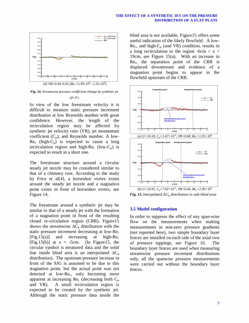
In view of the low freestream velocity it is difficult to measure static pressure increment distribution at low Reynolds number with great confidence. However, the length of the recirculation region may be affected by synthetic jet velocity ratio (VR), jet momentum coefficient (Cµ), and Reynolds number. A low-Rec (high-Cµ) is expected to cause a long recirculation region and high-Rec (low-Cµ) is expected to result in a short one. The freestream structure around a circular steady jet nozzle may be considered similar to that of a chimney root. According to the study by Frice et al[4], a horseshoe vortex exists around the steady jet nozzle and a stagnation point exists in front of horseshoe vortex, see Figure 14. The freestream around a synthetic jet may be similar to that of a steady jet with the formation of a stagnation point in front of the resulting closed re-circulation region (CRR). Figure15 shows the streamwise ∆Cp distribution with the static pressure increment decreasing at low-Rec [Fig.15(a)] and increasing at high-Rec [Fig.15(b)] at x = -5cm. (In Figure15, the circular symbol is measured data and the solid line inside blind area is an interpolated ∆Cp distribution). The upstream pressure increase in front of the SJG is assumed to be due to this stagnation point, but the actual point was not detected at low-Rec, only becoming more apparent at increasing Rec (decreasing both Cµ and VR). A small recirculation region is expected to be created by the synthetic jet. Although the static pressure data inside the
blind area is not available, Figure15 offers some useful indication of the likely flowfield. A low-Rec, and high-Cµ (and VR) condition, results in a long recirculation in the region -6cm < x < 19cm, see Figure 15(a). With an increase in Rec, the separation point of the CRR is displaced downstream and evidence of a stagnation point begins to appear in the flowfield upstream of the CRR.
-20 -15 -10 -5 0 5 10 15 20 25 30X (cm)
-0.03
-0.02
-0.01
0
0.01
0.02
0.03
SJRef
Cp
Reattachment pointSeparation point
Interpolated pressuredistribution
(a) U=16.18, Cµ=1.67×10⁻⁴, VR=0.68, Rec=1.55×10⁶
-20 -15 -10 -5 0 5 10 15 20 25 30X (cm)
-0.03
-0.02
-0.01
0
0.01
0.02
0.03
SJRef
Cp
Interpolated pressuredistribution
Separation point Reattachment point
(b) U=24.92, Cµ=7.02×10⁻⁵, VR=0.44, Rec=2.39×10⁶
Fig. 15. Interpolated Cp distribution in side blind area
3.5 Model configuration In order to suppress the effect of any span-wise flow on the measurements when making measurements in non-zero pressure gradients (not reported here), two simple boundary layer fences are installed on each side of the axial row of pressure tappings, see Figure 16. The boundary layer fences are used when measuring streamwise pressure increment distributions only, all the spanwise pressure measurements were carried out without the boundary layer fences.

Young-Hwan KIM, K.P.Garry
8
(a) Definition of boundary layer fence arrangement
(b) Boundary layer fence installation
Fig. 16. Boundary layer fence installation on flat plate
3.6 Effect of slot yaw angle The effect of changes in SJG slot yaw angle (β) have previously been reported by Kim[10], who shows that =20 is the optimum. As a result this value is adopted throughout the current study, with data for =0 being included, where appropriate, for comparison purposes.
3.7 Effect of variation in jet momentum coefficient (Cµ) The effect of changes in freestream velocity on the spanwise ΔCp distribution for both the synthetic jet and vane VG in a plane at x = 50mm are shown in Figure 17. Given that the SJG excitation frequency is kept constant at the resonance frequency (1.5KHz in this experiment), changes in the freestream flow velocity (U) effectively change the jet momentum coefficient (C). As was seen for the measurements made in a zero freestream pressure gradient, regions of +ve and -ve surface static pressure increment are generated downstream around the vortex core. Whilst changes in freestream velocity (Rex) appear to have little influence on the
effectiveness of the vane VG, regions of –ve pressure created by the synthetic jet are seen to dissipate with increasing Rex. The magnitude of the +ve pressure increment (ΔCp ) caused by the SJG is also reduced with increasing Rex but the region influenced does not diminish. This would appear to suggest that, within the limited Rex and C range considered, a synthetic jet has the potential to make small changes to the surface static pressure distribution and could be considered as an effective shape change of an aerofoil at high-Rex (low-C), where streamwise vortex is not able to be generated by a synthetic jet.
-50 0 50Y/H
-0.1
-0.075
-0.05
-0.025
0
0.025
0.05
0.075
0.1
SJ 00 degSJ 20 degVG 20 degRef
Cp
(a) C=5.9910-4, VR=1.30, Rex=1.75×10⁵ U=8.53m/s
-50 0 50Y/H
-0.1
-0.075
-0.05
-0.025
0
0.025
0.05
0.075
0.1
SJ 00 degSJ 20 degVG 20 degRef
Cp
(b) C=3.9510-4, VR=1.05, Rex=2.16×10⁵ U=10.51m/s
-50 0 50Y/H
-0.1
-0.075
-0.05
-0.025
0
0.025
0.05
0.075
0.1
SJ 00 degSJ 20 degVG 20 degRef
Cp
(c) Cµ=2.70×10⁻⁴, VR=0.87, Rex =2.61×10⁵, U=12.70m/s

9
THE EFFECT OF A SYNTHETIC JET ON THE PRESSURE DISTRIBUTION OF A FLAT PLATE
-50 0 50Y/H
-0.1
-0.075
-0.05
-0.025
0
0.025
0.05
0.075
0.1
SJ 00 degSJ 20 degVG 20 degRef
Cp
(d) C=2.1110-4, VR= 0.77, Rex=2.95×10⁵ U=14.38m/s
-50 0 50Y/H
-0.1
-0.075
-0.05
-0.025
0
0.025
0.05
0.075
0.1
SJ 00 degSJ 20 degVG 20 degRef
Cp
(e) C=1.4010-4, VR=0.63, Rex=3.62×10⁵, U=17.65m/s
-50 0 50Y/H
-0.1
-0.075
-0.05
-0.025
0
0.025
0.05
0.075
0.1
SJ 00 degSJ 20 degVG 20 degRef
Cp
(f) C=1.1210-4, VR=0.56, Rex=4.05×10⁵, U=19.76m/s
-50 0 50Y/H
-0.1
-0.075
-0.05
-0.025
0
0.025
0.05
0.075
0.1
SJ 00 degSJ 20 degVG 20 degRef
Cp
(g) C=1.0410-4,VR=0.54,Rex=4.21×10⁵,U=20.52m/s
-50 0 50Y/H
-0.1
-0.075
-0.05
-0.025
0
0.025
0.05
0.075
0.1
SJ 00 degSJ 20 degVG 20 degRef
Cp
(h) C=6.1610-5, VR=0.42, Rex=5.46×10⁵ U=26.60m/s
Fig 17. Effect of C and Rex for spanwise Cp distribution
(x=50mm)
3.8 Effect of the synthetic jet on the downstream flowfield Incremental surface static pressure data within the flowfield downstream of both the SJG (slot angle, β=20°) and the VG, can be used to generate surface pressure contours to aid general comparison of the key flow characteristics, see Figure 18. The streamwise location of VG is identical with that of SJG (x=0mm). It is evident that regions of increasing pressure (+ΔCp), in the flowfield downstream of the vane VG particularly, dominate at the higher Reynolds numbers tested. Whilst the pressure changes which lead to the virtual aeroshaping concept have been reported by previous researchers, data which quantifies the lateral extent of the area of increasing pressure has not previously been available.
4 Conclusions Analysis of the surface static pressure distribution on a plate downstream of a both a conventional vane vortex generator and the synthetic jet produced by efflux from an inclined rectangular slot, is used to understand the resulting flow structure. The position of the streamwise vortex core and the sense of the vortex rotation are assessed using the distribution of spanwise pressure coefficient change (Cp). A clear suction peak locates the vortex core and the higher pressure at one side of vortex core represents the downwash of the vortex which implies the sign of vortex rotation.

Young-Hwan KIM, K.P.Garry
10
The magnitude of ΔCp can be used to infer the effect of changes in vortex intensity and vertical displacement. The effectiveness of a synthetic jet is highly dependent on slot yaw angle (β). Two SJG angles are investigated β=0° and 20° which exhibit fundamentally different downstream flow features. The SJG with β=0° creates a CVP (Counter-rotating Vortex Pair) within the boundary layer, while β=20° produces a single streamwise vortex. The effect of these two slot yaw angles are compared with a vane type vortex generator (β=20°). Since β=20° caused higher pressure and suction in the downstream flowfield than β=0°, a single streamwise vortex (caused by β=20°) is considered to be more effective than a CVP (caused by β=0°) in terms of its potential for boundary layer control. At a Reynolds number (Rex) of 1.75105, the SJ (β=20°) produces a greater downstream surface static pressure increments than the conventional vane VG (β=20°). As for steady jet, the effect of a synthetic jet is seen to diminish with increasing Rex (synthetic jet velocity constant) while the effect of a vane VG is seen to be unaffected in the Rex range considered. The streamwise vortices created by a VG (β=20°) and SJ (β=20°) drift in a spanwise direction due to the geometric asymmetry of the synthetic jet slot and vortex generator vane. As the vane type vortex generator angle (β) affects the resulting vortex rotation direction, and the orientation of a synthetic jet slot also affects the resulting streamwise vortex rotation direction. Therefore, by adjusting the slot yaw angle in a multiple slot arrangement, a co-rotating vortex and counter-rotating vortex arrangement can be generated. A synthetic jet is also seen to affect the flowfield upstream of the slot. At low Reynolds number (Rex=1.17105, Cµ=5.99×10⁻⁴), a synthetic jet caused a local pressure reduction at x = -50mm, while at high Reynolds number (Rex=3.14105, Cµ=8.29×10⁻⁵) a SJG resulted in a pressure increase at the same axial location. This local suction is considered to be due to the
closed recirculation region, which extends to x = -50mm at low-Rex. mailto:[email protected]
References [1] Young-Hwan KIM, and K.P. Garry. Time Dependent
Analysis of A Rectangular Synthetic Jet. ICAS 2012, 23 - 28 September 2012, Brisbane, Australia
[2] K.G. Peterson, R. Funk, and N.M. Komerath, Recent Experiments on Vortex Collisions with a Cylinder, AIAA 95-2236, June. 1995
[3] X.Zhang and M.W.Collins, Measurements of a longitudinal vortex generated by a rectangular jet in a turbulent boundary layer, Phys. Fluid Vol. 9, No. 6, 1997
[4] T.F.Fric and A.Roshko, Vortical structure in the wake of transverse jet, J. Fluid Mech, vol 279, pp1-47, 1994
[5] N.W.Schaeffler and L.N.Jenkins. The Isolated Synthetic Jet in Crossflow: A Benchmark for Flow Control Simulation, AIAA 2004-2219, 2004
[6] C.G.Lomas. Fundamentals of Hot Wire Anemometry, Cambridge University Press, 1985
[7] E.M.Greitzer, C.S.Tan and M.B.Graf Internal Flow: Concepts and Applications, Cambridge University Press, 2007.
[8] J.Proakis and D.G.Manolakis Digital Signal Processing: Principles, Algorithms, and Applications, Prentice Hall International Editions
[9] Murata Manufacturing Company Ltd, “PZT Application Manual”.
[10] Young-Hwan KIM. The effect of rectangular synthetic jet to the flat plate boundary layer in low Reynolds number, Experimental Fluid Mechanics 2011, Jičin, Czech Republic, Vol.2, pp 727-746, 2011.
[11] Young-Hwan KIM A Parametric Investigation of Synthetic Jet and its Boundary Layer Control, Ph.D Thesis, Cranfield University, 2005.
Copyright Statement The authors confirm that they, and/or their company or organization, hold copyright on all of the original material included in this paper. The authors also confirm that they have obtained permission, from the copyright holder of any third party material included in this paper, to publish it as part of their paper. The authors confirm that they give permission, or have obtained permission from the copyright holder of this paper, for the publication and distribution of this paper as part of the ICAS 2014 proceedings or as individual off-prints from the proceedings.

11
THE EFFECT OF A SYNTHETIC JET ON THE PRESSURE DISTRIBUTION OF A FLAT PLATE
-0.05
0
0.0550
100
150
200
250
300
X(m
m)
-50
0
50
Y/H
Delta Cp0.03229410.02679510.0212960.0157970.0102980.00479897
-0.000700047-0.00619907-0.0116981-0.0171971-0.0226961-0.0281951-0.0336942-0.0391932-0.0446922
Cp
Synthetic jet
-0.05
0
0.0550
100
150
200
250
300
X(m
m)
-50
0
50
Y/H
Delta Cp0.03229410.02679510.0212960.0157970.0102980.00479897
-0.000700047-0.00619907-0.0116981-0.0171971-0.0226961-0.0281951-0.0336942-0.0391932-0.0446922
Cp
Synthetic jet
-0.05
0
0.0550
100
150
200
250
300
X(m
m)
-50
0
50
Y/H
Delta Cp0.03229410.02679510.0212960.0157970.0102980.00479897
-0.000700047-0.00619907-0.0116981-0.0171971-0.0226961-0.0281951-0.0336942-0.0391932-0.0446922
Cp
Synthetic jet
-0.05
0
0.0550
100
150
200
250
300
X(m
m)
-50
0
50
Y/H
Delta Cp0.03229410.02679510.0212960.0157970.0102980.00479897
-0.000700047-0.00619907-0.0116981-0.0171971-0.0226961-0.0281951-0.0336942-0.0391932-0.0446922
Cp
Vortex generator
-0.05
0
0.0550
100
150
200
250
300
X(m
m)
-50
0
50
Y/H
Delta Cp0.03229410.02679510.0212960.0157970.0102980.00479897
-0.000700047-0.00619907-0.0116981-0.0171971-0.0226961-0.0281951-0.0336942-0.0391932-0.0446922
Cp
Vortex generator
-0.05
0
0.0550
100
150
200
250
300
X(m
m)
-50
0
50
Y/H
Delta Cp0.03229410.02679510.0212960.0157970.0102980.00479897
-0.000700047-0.00619907-0.0116981-0.0171971-0.0226961-0.0281951-0.0336942-0.0391932-0.0446922
Cp
Vortex generator
(a) U=8.53 m/s, C=5.9910-4, VR=1.30, Rec=8.17×10⁵
(b) U=10.51m/s, C=3.9510-4, VR=1.05, Rec=1.01×10⁶
(c) U=12.70m/s, C=2.7010-4, VR=0.87, Rec=1.22×10⁶

Young-Hwan KIM, K.P.Garry
12
-0.05
0
0.0550
100
150
200
250
300
X(m
m)
-50
0
50
Y/H
Delta Cp0.03229410.02679510.0212960.0157970.0102980.00479897
-0.000700047-0.00619907-0.0116981-0.0171971-0.0226961-0.0281951-0.0336942-0.0391932-0.0446922
Cp
Synthetic jet
-0.05
0
0.0550
100
150
200
250
300
X(m
m)
-50
0
50
Y/H
Delta Cp0.03229410.02679510.0212960.0157970.0102980.00479897
-0.000700047-0.00619907-0.0116981-0.0171971-0.0226961-0.0281951-0.0336942-0.0391932-0.0446922
Cp
Synthetic jet
-0.05
0
0.0550
100
150
200
250
300
X(m
m)
-50
0
50
Y/H
Delta Cp0.03229410.02679510.0212960.0157970.0102980.00479897
-0.000700047-0.00619907-0.0116981-0.0171971-0.0226961-0.0281951-0.0336942-0.0391932-0.0446922
Cp
Synthetic jet
-0.05
0
0.0550
100
150
200
250
300
X(m
m)
-50
0
50
Y/H
Delta Cp0.03229410.02679510.0212960.0157970.0102980.00479897
-0.000700047-0.00619907-0.0116981-0.0171971-0.0226961-0.0281951-0.0336942-0.0391932-0.0446922
Cp
Vortex generator
-0.05
0
0.0550
100
150
200
250
300
X(m
m)
-50
0
50
Y/H
Delta Cp0.03229410.02679510.0212960.0157970.0102980.00479897
-0.000700047-0.00619907-0.0116981-0.0171971-0.0226961-0.0281951-0.0336942-0.0391932-0.0446922
Cp
Vortex generator
-0.05
0
0.0550
100
150
200
250
300
X(m
m)
-50
0
50
Y/H
Delta Cp0.03229410.02679510.0212960.0157970.0102980.00479897
-0.000700047-0.00619907-0.0116981-0.0171971-0.0226961-0.0281951-0.0336942-0.0391932-0.0446922
Cp
Vortex generator
(d) U=14.38m/s, C=2.1110-4, VR=0.77, Rec=1.38×10⁶
(e) U=16.18 m/s, C=1.6710-4, VR=0.68, Rec=1.55×10⁶
(f) U=19.76m/s, C=1.1210-4, VR=0.56, Rec=1.89×10⁶

13
THE EFFECT OF A SYNTHETIC JET ON THE PRESSURE DISTRIBUTION OF A FLAT PLATE
Fig. 18. Static pressure coefficient change (Cp) in the downstream flowfield
-0.05
0
0.0550
100
150
200
250
300
X(m
m)
-50
0
50
Y/H
Delta Cp0.03229410.02679510.0212960.0157970.0102980.00479897
-0.000700047-0.00619907-0.0116981-0.0171971-0.0226961-0.0281951-0.0336942-0.0391932-0.0446922
Cp
Synthetic jet
-0.05
0
0.0550
100
150
200
250
300
X(m
m)
-50
0
50
Y/H
Delta Cp0.03229410.02679510.0212960.0157970.0102980.00479897
-0.000700047-0.00619907-0.0116981-0.0171971-0.0226961-0.0281951-0.0336942-0.0391932-0.0446922
Cp
Synthetic jet
-0.05
0
0.0550
100
150
200
250
300
X(m
m)
-50
0
50
Y/H
Delta Cp0.03229410.02679510.0212960.0157970.0102980.00479897
-0.000700047-0.00619907-0.0116981-0.0171971-0.0226961-0.0281951-0.0336942-0.0391932-0.0446922
Cp
Vortex generator
-0.05
0
0.0550
100
150
200
250
300
X(m
m)
-50
0
50
Y/H
Delta Cp0.03229410.02679510.0212960.0157970.0102980.00479897
-0.000700047-0.00619907-0.0116981-0.0171971-0.0226961-0.0281951-0.0336942-0.0391932-0.0446922
Cp
Vortex generator
(g) U=22.94 m/s , C=8.2810-5, VR=0.48, Rec=2.20×10⁶
(h) U=26.60 m/s, C=6.1610-5, VR=0.42, Rec=2.55×10⁶