the edward s. rogers sr. department of electrical and...
TRANSCRIPT

THE TRANSMISSION-LINE PARADIGM FOR METAMATERIALS:
FUNDAMENTALS & SELECTED APPLICATIONS
George V. Eleftheriades
The Edward S. Rogers Sr. Department of Electrical and Computer EngineeringElectrical and Computer Engineering
The University of TorontoCANADA

METAMATERIALS
META=“BEYOND” IN GREEK
Artificial materials with unusual electromagnetic properties that are difficult to encounter in nature.
ARTIFICIAL DIELECTRICS:ARTIFICIAL DIELECTRICS:
• W.E. Kock “Metallic delay lenses”, Bell Syst. Tech. J., vol. 27, pp. 58-82, Jan. 1948.• R.N. Bracewell, “Analogues of an ionized medum”, Wireless Eng. Dec. 1954.• S.B. Cohn, “The electric and magnetic constants of metallic delay media containing obstacles of
bi h d hi k ” J l f A li d Ph i l 22 M 1951arbitrary shape and thickness,” Journal of Applied Physics, vol. 22, May, 1951.• W. Rotman, “Plasma simulation by artificial dielectrics and parallel-plate media”, IRE Trans. on
Antennas and Propagation, Jan. 1962. • R. E. Collin, Field Theory of Guided Waves, Piscataway, N.J.: IEEE Press, 1990 (chapter 12).
TRANSMISSION-LINE METAMATERIALS:SMISSION-LINE METAMATERIALS:
Artificial dielectrics synthesized by periodically loading a host transmission-linemedium with R L C lumped elements: Periodicity << although non-periodicmedium with R,L,C lumped elements: Periodicity << although non-periodicMTMs could also be defined).

J.B. Pendry
Artificial Molecules1948
2001 2008
tt
2001
ww
ddhh
dd

FUNDAMENTALS

LEFT-HANDED AND METAMATERIALS
Veselago, 1960s0,0
Backward Waves0,0 ,
kk
E
HSH
S
Regular Materials
(right handed)
Left-handed Materialsn
EE
(right-handed)
Negative-Refractive-Index (NRI) Materials

NEGATIVE REFRACTION
0n
air
1 2
2n
2
1sinsin
0n
Negative-Refractive-Index (NRI) MediaNegative Refractive Index (NRI) Media

RECONCEPTUALIZING AND METAMATERIALS
Start from the transmission-line representation of normal dielectrics:
SL
SLj
SjXj
jX
S
jX jBS
CSCj
SjBj
S
How to synthesize How to synthesize

Simply: Make the series reactance X and h b h ishunt susceptance B both negative!
jX LjjBj
2
1)/1(
jX jB
SLSSj
2
SCSCj
SjXj
21)/1(
SSCSS 2
G.V. Eleftheriades, A.K. Iyer and P.C. Kremer, “Planar negative refractive index media using periodically L-C loaded transmission lines,” IEEE Trans. on Microwave Theory and Techniques, vol. 50, no. 12, pp. 2702-2712, Dec. 2002.vol. 50, no. 12, pp. 2702 2712, Dec. 2002.
L. Liu, C. Caloz, C. Chang, T. Itoh, "Forward coupling phenomenon between artificial left-handed transmission lines," J. Appl. Phys., vol. 92, no. 9 , pp. 5560-5565, 2002.


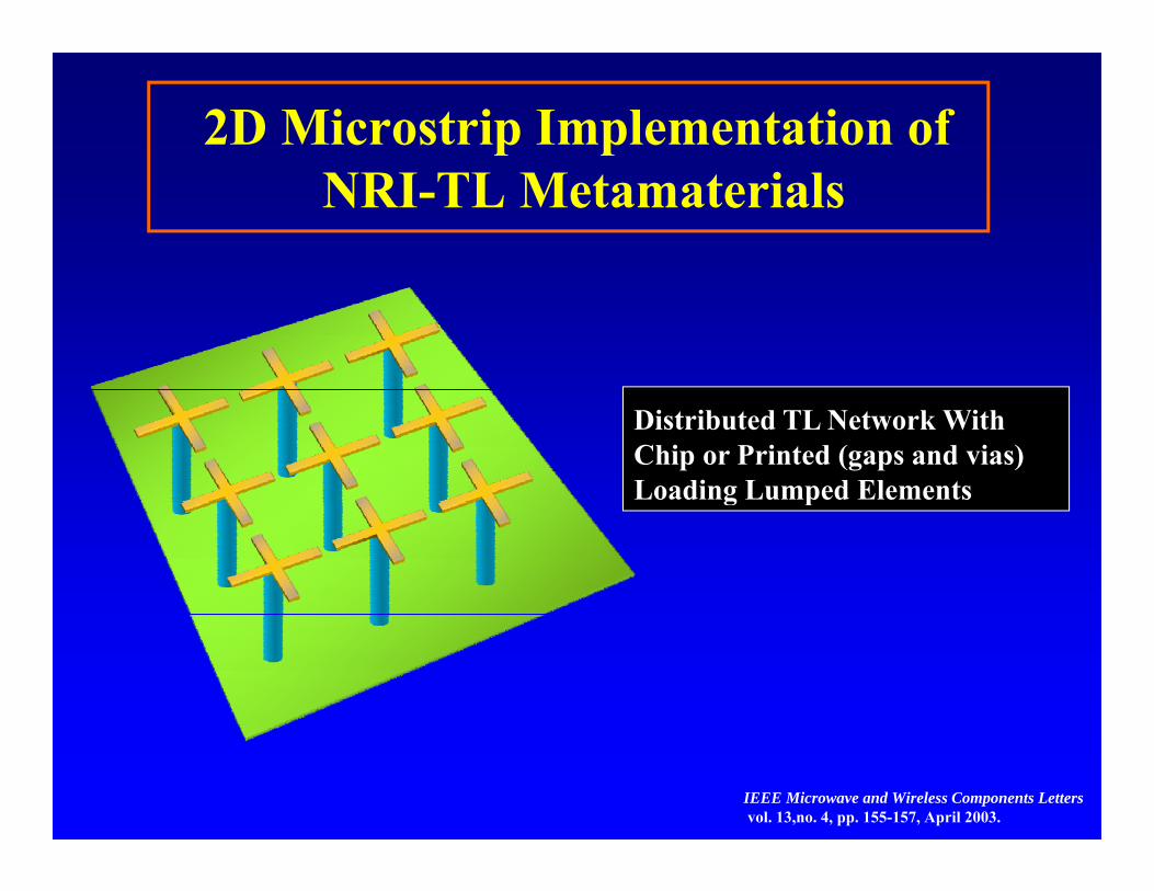
2D Microstrip Implementation ofNRI-TL Metamaterials
Distributed TL Network With Chip or Printed (gaps and vias) Loading Lumped Elementsg p
IEEE Microwave and Wireless Components Lettersvol. 13,no. 4, pp. 155-157, April 2003.

Effective Medium Approach for a Left-Handed Loaded Parallel-Plate Waveguide (PPW)
Hy mp
p p pmp
E
d
zep ep ep
eo PjEjH dL
EPe 2 (x-z loop)Ampere’s Law:
dLo
moo PjHjE dC
HPoo
m 2 (y-z loop)Faraday’s Law:
Equivalent PPW filled with effective media parameters
)/(1 2 dLooeff
)/(1 2 dCooeff
Negative-Refraction Metamaterials: Fundamental Principles and Applications. Editors G.V. Eleftheriades and K.G. Balmain(John Wiley & Sons and IEEE Press); contributed four chapters. ISBN: 0-471-60146-2, June 2005.

SPATIAL HARMONICS IN NRI-TL
j
Proc. of the IEEE European Microwave Conference, pp. 504-507, Sept. 29-Oct.1 2009, Rome, Italy.
2
n
zjn
neuzV )(
n 2
an
n 2
an
Infinite number of forward and backward harmonics
0n0n 0n
Just how much power is contained in the fundamental n=0 BW harmonic?
In the homogeneous limit
f h
C=2.2pF, L=1.1nH@ f=2.8GHzo
oa 281,1 kaa most of the power
is carried by the fundamental (n=0) spatial harmonic
Black line: % power in the right-handed mode (n=0)
Red line: % power in the left-handed mode (n=0)

PHASE EVOLUTION: How does a Backward Wave Form? (5 unit cells: phase of the current wave)
On the interconnecting TL there is a phase delay; the phase advances from one unit cell to the next due to the phase jumps on the shunt inductors (for the current).
On the AVERAGE the phase linearly advances with distance
The departure from the average becomes smaller and smaller as the unit cell becomes smaller

Backward_wave on an NRI TL

BROADBAND/LOW-LOSS NATURE OF TL-BASED METAMATERIALS
1/p=normalized coupling coefficient between adjacent loops
G.V. Eleftheriades, “Analysis of Bandwidth and Loss in NRI-TL Media Using Coupled Resonators,”IEEE Microwave and Wireless Components Letters, June 2007.

NEGATIVE REFRACTION OF A GAUSSIAN BEAM IN NRI-TL METAMATERIALSIN NRI TL METAMATERIALS
Power refracts negatively
M. Zedler and G.V. Eleftheriades, 2009

1D APPLICATIONS

A LEAKY BACKWARD-WAVE ANTENNA (fan beam)
F 15GHF=15GHzBACKWARD Radiation from the FUNDAMENTAL Spatial harmonic
−30 30
0
−20 −10 0
−60
−90 90
60
−20 −10 0
120
−90 90
−120
150−150
−180
A. Grbic and G.V. Eleftheriades, “Experimental verification of backward-waveradiation from a negative refractive index metamaterial.” Journal of AppliedPhysics, vol. 92, pp. 5930-5935, Nov. 2002.

2D NRI-TL Leaky-Wave AntennaPRI-TL
Closed Stop Band
quen
cy
NRI-TL
Source
o
oo
CLZ
2
Freq
zo
x
Directivity
T. Kokkinos, C.D. Sarris and G.V. Eleftheriades, “Periodic FDTD analysis of leaky-wave structures and applications tothe analysis of negative-refractive-index leaky-wave antennas,” IEEE Trans. on Microwave Theory Tech., May 2006.

REDUCED BEAM-SQUINTING LEAKY-WAVE ANTENNA (in planar CPS )
4.5 GHz 5.0 GHz 5.5 GHz
M. Antoniades and G.V. Eleftheriades, IEEE Trans. on Antennas and Propagat., vol. 56, no. 3, pp. 708-721, March 2008.

Zero-Degree Phase-Shifting LinesZero Degree Phase Shifting Lines
- +Phase Compensation with RHM/LHM LinesMeasured vs. Simulated
Phase Compensation with RHM/LHM Lines
Conventional 1 line
M A t i d d G V El fth i d “C t Li L d/L M t t i l PhM. Antoniades and G.V. Eleftheriades, “Compact, Linear, Lead/Lag Metamaterial Phase Shifters for Broadband Applications,” IEEE Antennas and Wireless Propagation Letters, vol. 2, issue 7, pp. 103-106, July 2003.

COMPACT AND BROADBAND SERIES POWER DIVIDERSSERIES POWER DIVIDERS
Metamaterial 1:4 Divider Transmission-Line 1:4 Divider
Non-Radiating Lines
DRAMATIC AREA REDUCTION

BROADBAND:
M A t i d d G V El fth i d “A B db d S i P Di id U iM. Antoniades and G.V. Eleftheriades, “A Broadband Series Power Divider Using Zero-Degree Metamaterial Phase-Shifting Lines”, IEEE MWCL, Nov. 2005

Tunable MMIC NRI-TL Phase Shifter0.13m CMOS MMIC zero-degree phase-shifter (active inductors)(RH TL l d b l d L C ti t d i I t ti )(RH-TLs replaced by lumped L-C sections to reduce size Integration)
The phase of a unit-cell can be electronically tuned from -35o to +59o at 2.6GHz, while maintainingS11<-19dB. Across the entire phase tuning range S21 varies from -2.8dB to -3.8dB at 2.6GHz.
-----------------------------------------------------------------------------------------------------------------------------------------------------------------------------------------------------------------------------------------------------------------------------------------------------------------------------------------------------------------------------------------------------
M.A.Y. Abdalla, K. Phang and G.V. Eleftheriades, “Printed and integrated CMOS positive/negative refractive-index phase shiftersusing tunable active inductors,” IEEE Trans. Microw. Theory Tech., vol. 8, August 2007.

Steerable Series-fed Patch Array
Inter-stage phase shifters
22.6cm
7.1cm
DC bias and control inputsAntenna array
RF i t/ t t
• The array consists of 4 patch antennas and uses 3 inter-stage phase shifters
RF input/output
e a ay co s sts o patc a te as a d uses 3 te stage p ase s te s• The entire antenna array ( which includes: patches, feed-lines, and the phase shifters) is
designed on a single 2-layer board• All the inter-stage phase shifter receive the bias and control signals from a ribbon cable
on the bottom side of the board
M.A.Y. Abdalla, K. Phang, and G.V. Eleftheriades, “A steerable series-fed phased array architecture using tunable PRI/NRI phase shifters”, Intl. Workshop on Antenna Technology (IWAT), March 4-6, Chiba University, Japan, March 4-6, 2008.

Experimental ResultsTh d i tt th i th l l
0 1530
4545-30
-15
The measured gain patterns versus the azimuthal angle
10
45
60
75-75
-60
-45
-10
0
(dB
i)
90
105
120-120
-105
-90 -20
-10-30
-20Gai
n (
135150
165180-165-150
-135 0
10-100 -50 0 50 100-40
Azimuthal angle (deg)
• The measured scan angle ranges from +18o to -27o at 2.4GHz by changing the TAI bias voltages and the varactor control voltage from 3V to 15V. • The antenna gain changes from 8.4 to 7.1dBi across the entire 45o scan angle range• Relative side-lobe level < -10dBRelative side lobe level 10dB•Very little beam-squinting vs frequency
M. A.Y. Abdalla, K. Phang, and G.V. Eleftheriades "A planar electronically steerable patch array using tunable PRI/NRI phase shifters,” IEEE Trans. on Microwave Theory and Techniques, vol. 57, pp. 531-541, March 2009.

Electrically Small NRI-TL Zero-Index Antennas
Shunt Inductor L0
Series Capacitor C0
1.23mm C0
MTMunit
ll
1.23mm C0
MTMunit
1.23mm C0
1.23mm C0L0
via via
viavia
0.4mm
C0
0
C0
L0
L0 L0
L0 cell
0.4mm
C0
C0
C0
L0
L0L0
L0 cell
0.4mm
C0
C0
C0
L0
L0L0
L0 MTMunitcell
0.4mm
C0
C0
C0
L0
L0L0
L0 MTMunitcell
via
Coaxial Feed
4.8mm C0 4.8mm C0 4.8mm C0 4.8mm C0
Main idea: Wrap around a 0Main idea: Wrap around a 0°° MTM phaseMTM phase--shifting line to make a small resonant antennashifting line to make a small resonant antennaMain idea: Wrap around a 0Main idea: Wrap around a 0 MTM phaseMTM phase shifting line to make a small resonant antenna shifting line to make a small resonant antenna
G.V. Eleftheriades, A. Grbic, M. Antoniades, "Negative-Refractive-Index Transmission-Line Metamaterials and Enabling Electromagnetic Applications," 2004 IEEE Antennas and Propagation Society International Symposium Digest, pp. 1399-1402, Monterey, CA, USA, June 20-25, 2004.

Measured Antenna PatternsMeasured Antenna PatternsMeasured radiation efficiency up to 70-80% W x L x H = λ /11 x λ /14 x λ /31Bandwidth: 1-3% (-10dB point) W x L x H = λ0/11 x λ0/14 x λ0/31
−5
0
−15
−10
S11
(d
B)
−25
−20
S1
SimulatedMeasured
1.5 1.6 1.7 1.8 1.9 2−30
Frequency (GHz)
Measured
M.A. Antoniades and G.V. Eleftheriades, “A folded-monopole model for electrically small NRI-TL metamaterial antennas," IEEE Antennas and Wireless Propagat. Letters, vol. 7, pp. 425-428, 2008.

A Compact Zero-Index NRI-TL Metamaterial Antenna with Extended Bandwidth (double-tuned matching)( g)
-5
0
-15
-10
5
(dB
)
30
-25
-20|S11
| 2.5 3 3.5 4
-35
-30
Frequency (GHz)
measuredsimulated
1. Doubly resonant MTM Structure
2. More than doubled the bandwidth compared with the singly resonant p g yMTM antenna
J. Zhu and G.V. Eleftheriades, “A compact transmission-line metamaterial antenna with extended bandwidth,” IEEE Antennas and Wireless Propagat. Letters , vol. 08, pp. 295-298, 2009.

‘DUAL-MODE’ BROADBAND NRI-TL MONOPOLE
Unloaded monopole antennaUnloaded monopole antenna Single NRISingle NRI--TL cell loaded monopoleTL cell loaded monopole
A single resonance A single resonance at 6.4 GHzat 6.4 GHz
A dual resonance at A dual resonance at 3.5 GHz and 5.5 GHz.3.5 GHz and 5.5 GHz.
M.A. Antoniades and G.V. Eleftheriades, “A broadband dual-mode monopole antenna using NRI-TL metamaterial loading,” IEEE Antennas and Wireless Propagat. Letters., vol 8, pp. 258-261, 2009.
BWBW--10dB10dB = 3.78GHz= 3.78GHz

High-Directivity Coupled-Line CouplerHigh Directivity Coupled Line Coupler
Coupled Microstrip/NRI TLines:Coupled Microstrip/NRI TLines:kMS SMS
CLL
MSNRIkNRI SNRI
Co directional phase flow but contraCo-directional phase flow but contra-directional power flow!
R. Islam and G.V. Eleftheriades, “A planar metamaterial co-directional coupler that couples power backwards.” 2003 IEEE Itnl. Microwave Symposium Digest, Philadelphia, June 8-13, pp. 321-324, 2003.

Conventional Microstrip vs. MS/NRICoupled-Line CouplerCoupled Line Coupler
150.4mm
P1 P2 P1 P2•Equal length•Equal line spacing15mm
2.1mm
P4P3 P3 P4
•Equal line spacing•Equal propagation constant
MS-NRI MS-MS
MS/MS Directivity: 8dB
MS/NRI Directivity: 20dB
R. Islam and G.V. Eleftheriades, “A planar metamaterial co-directional coupler that couples power backwards.” 2003 IEEE Itnl. Microwave Symposium Digest, Philadelphia, June 8-13, pp. 321-324, 2003.

Metamaterial MS/NRI 3dBMetamaterial MS/NRI 3dB Coupler
Operates in coupled mode stop band
Arbitrary coupling levels by increasing coupler l hlength

Metamaterial MS/NRI 3dBMetamaterial MS/NRI 3dB Coupler
Operates in coupled mode stop band
Arbitrary coupling levels by increasing coupler l hlength

Metamaterial MS/NRI 3dBMetamaterial MS/NRI 3dB Coupler
Operates in coupled mode stop band
Arbitrary coupling levels by increasing coupler l hlength
Phase Progression With
R. Islam, F. Elek and G.V. Eleftheriades, “A coupled-line metamaterial coupler having co directional phase but contra directional power flow ” Electronics
Exponential Field Variation
having co- directional phase but contra-directional power flow.” Electronics Letters, vol. 40, no. 5, March 04, 2004.

Operation in Coupled-Mode Stop BandOperation in Coupled Mode Stop Band|V1|
Sz
S
Line 1 (MS)Input
( )Line 2 (NRI)
pCoupled
|V |S Isolated
|V2|
z

3dB Coupler: Experimental Results
• Operating frequency –3GHz
• Cell size 4mm• Cell size – 4mm• Line width – 2.34mm• C - 1.3pF, L - 3.3nH• #of unit cells – 6
R. Islam, F. Elek and G.V. Eleftheriades, “A coupled-line metamaterial coupler having co- directional phase but contra-directional power flow.” Electronics Letters, vol. 40, no. 5, March 04, 2004.

FULLY PRINTED HIGH-DIRECTIVITY REFLECTOMETER
Solid Line: Measured
12
MSNRI
34
MSNRI
4 Shorted Stubs
Interdigital Capacitor
Coupling : –27 dB Isolation: –72 dB Di ti it 45 dB
@ f=2.04 GHzDirectivity: 45 dB
R. Islam and G.V. Eleftheriades, IEEE MWCL, pp. 164-166 April 2006.

2D AND VOLUMETRIC APPLICATIONS: SUPERLENSES
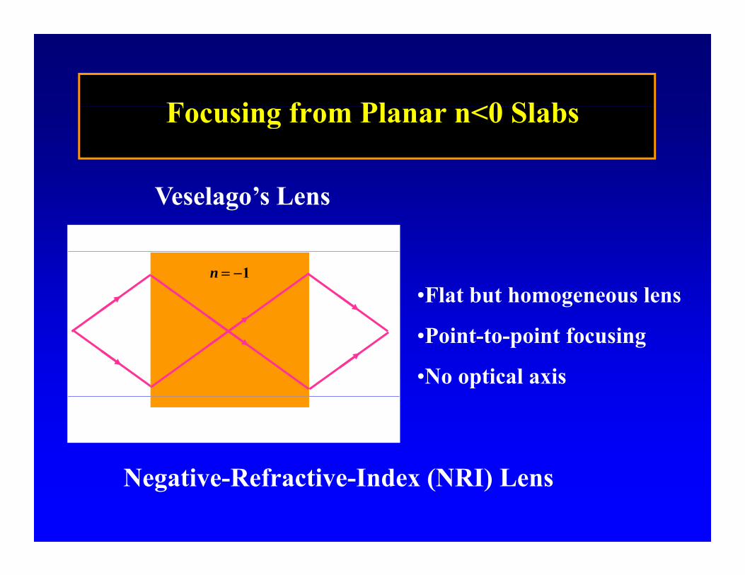
F i f Pl <0 Sl bFocusing from Planar n<0 Slabs
Veselago’s Lens
1n
•Flat but homogeneous lens
•Point-to-point focusing
•No optical axis
N i R f i I d (NRI) LNegative-Refractive-Index (NRI) Lens

ISOTROPIC 3D NRI-TL METAMATERIAL
4.00 mm
3.50 mm
2.00 mm
o, o x
y z
10.00 mm
A. Grbic and G.V. Eleftheriades, “An isotropic three-dimensional negative-refractive-index transmission-line metamaterial,” Journal of Applied Physics, 98, pp. 043106, Aug. 15 (2005).transmission line metamaterial, Journal of Applied Physics, 98, pp. 043106, Aug. 15 (2005).

VOLUMETRIC “STACKED” NRI-TL MEDIUM(layer-by-layer fabrication)
(layer-by-layer fabrication)
A source embedded in free-space
Ek0
E
H
k0 E
H
•A.K. Iyer and G.V. Eleftheriades, “A volumetric layered transmission-line metamaterial exhibiting a negative refractive index,” Journal of the Optical Society of America (JOSA-B), vol. 23, no. 3, pp. 553-570, March 2006.
•A.K. Iyer and G.V. Eleftheriades, “Characterization of a multilayered negative-refractive-index transmission-line (NRI-TL) metamaterial,” IEEE Intl. Microwave Symposium (IMS), San Francisco, CA, June 11-16, 2006.

NEGATIVE-REFRACTIVE-INDEX TRANSMISSION-LINE (NRI-TL) SUPERLENSTRANSMISSION LINE (NRI TL) SUPERLENS
R l i t /3 t @ 2 4GHResolving two sources /3 apart @ 2.4GHzDistance between source and image: 0.57
A.K. Iyer and G.V. Eleftheriades, Appl. Phys. Lett., 92, 131105, March 2008.
A.K. Iyer and G.V. Eleftheriades, “Free-space imaging beyond the diffraction limit using a Veselago-Pendry transmission-line metamaterial superlens,” IEEE Trans. Antennas and Propagat., vol. 57, pp. 1720-1727, June 2009.

HFSS Simulations=0 =15 =30 =45
“Isotropic” n = -1 evident from iso-frequency contour at 0
Clear Bloch a efronts forming (macroscopic)Clear Bloch-wavefronts forming (macroscopic)

Transmission-Line MTM Cloaks:Point Source Adjacent to a Metallic Cylinder
Without TL Cloak
With TL Cloak
M. Zedler and G.V. Eleftheriades, 2009

HYPERBOLIC TL METAMATERIALS
Unit Cell of K.G. Balmain’s Anisotropic TL Metamaterial
K. G. Balmain, A. A. E. Lüttgen, P. C. Kremer, “Resonance cone formation, reflection, refraction d f i i l i t i t t i l ” IEEE A t d Wi l P tiand focusing in a planar anisotropic metamaterial,” IEEE Antennas and Wireless Propagation
Letters, vol. 1, no. 7, pp. 146-149, 2002.

ANISOTROPIC RESONANCE-CONE METAMATERIALSUSING CONTINUOUS METALLIC GRIDS OVER
G OGROUND
2)()( yryxrx dfdf
NOTE: NO LUMPED ELEMENTS OR VIASSCALABLE

12 12
FOCUSING WITH CONTINUOUS HYPERBOLIC GRIDS OVER GROUND
0.3 mm 10.1mm
12.12mm
Y
8
9
10
F=10 GHz
Input
3
4
5
6 7
8
50 Resistive terminations
Vias to Ground X 0 2 1 3 4 5 6 7 8 9
1
2
3

Simulation Experiment F 0 763
Vol
ts
Source = 1
Focus = 0.84 Source = 1
Focus = 0.763
|S21
|
V
At Resonance (10 GHz) At Resonance (10.3 GHz)
X X Y Y
( )
Source = 1
Focus = 0.764 Source = 1 Focus = 0.752
| X
X Y
Y
Vol
ts |S21
Below Resonance (9.81 GHz) Below Resonance (10.15 GHz)
G.V. Eleftheriades and O.F. Siddiqui, “Negative refraction and focusing in hyperbolic t i i li id ” IEEE T Mi Th d T h i l 53 1transmission-line grids,” IEEE Trans. on Microwave Theory and Techniques, vol. 53, no. 1, pp. 396- 403, Jan. 2005.

A DIPLEXER BASED ON NEGATIVE REFRACTION AND SPATIAL FILTERING
6.2GHz Photonic-Crystal Metamaterial
No lumped elements (chip orprinted)
5.8 GHz5.8 GHz
O.F. Siddiqui, and G.V. Eleftheriades, Journal of Applied Physics, 99, 083102, April 15, 2006.

A Shifted-Bean Approach to Sub-wavelength Focusingg g
Slots are closely spaced (lambda/10) and close to resonanceThe spot size is NOT sensitive to lossesSimple to construct/frequency scalable structureResonance enhances field transmission
z
xy
Far-fieldNear-fieldNear field
L. Markley, A.M.H. Wong, Y. Wang and G.V. Eleftheriades, “Spatially shifted beam approach to sub-wavelength focusing,” Physical Review Letters, 101, 113901, Sept. 12, 2008.

Experimental Apparatus5 lit S t f 10GH λ 30
A il t E8364B
5-slit Screen at f = 10GHz, λ = 30mm
Agilent E8364B network analyzerxyz-translator
meta-screen
collimating lens
X-band horn antennaantenna probe

Experimental Results (2D Focusing)
15
5
10
measurements taken 7.5 mm above the screen (0.25λ) at 10 GHz
30mm by 30mm surface at 0.25mm incrementsshown at left in blue contours
0
5
z po
sitio
n (m
m)
satellite slots were covered by copper tape and the single-slot pattern measured
-10
-5
five-slot half-maximum contourdiffraction limit half-maximum contour
g pFWHM contour shown in red
beam width along the x axis 0 271λ and along-15 -10 -5 0 5 10 15
-15
x position (mm)
five-slot contours at 10% intervalsbeam width along the x-axis 0.271λ and along the z-axis is 0.385λ
G.V. Eleftheriades and A.M.H. Wong, “Holography inspired screens for sub-wavelength focusing in the near field,” IEEE Microwave. Wireless Compon. Letters, pp. 236-238, April. 2008.

Detecting Thru Reflection with S b l th R l tiSub-wavelength Resolution
1
For the two washer case, the array probe clearly resolves them at a separation of 0.4λ @ 0.25 away (a single dipole probe cannot).
0.8
1
nitu
de
array probedipole probe
0.4
0.6
ized
mag
0
0.2
norm
ali
-2 -1 0 1 20
x position ()L. Markley and G.V. Eleftheriades, IEEE IMS, June 09, 2009 Boston.

EMERGING TRENDS AND APPLICATIONSAPPLICATIONS
UNIQUE PROPERTIES CAN LEAD TO UNIQUE APPLICATIONS( i f i l i l h f l ki )(negative refraction, super-resolution, wavelength ~ freq, cloaking)
DIFFERENT PERSPECTIVE OF LOOKING AT THE WORLD!
RF/MICROWAVE PASSIVE COMPONENTSSMALL ANTENNAS ANTENNA BEAMFORMINGANTENNA BEAMFORMINGRCS MANAGEMENT/CLOAKINGMEDICAL IMAGINGTUNABLE AND ACTIVE METAMATERIAL STRUCTURESEMI REDUCTION USING METAMATERIAL GROUNDS THz COMPONENTSBEYOND NRI METAMATERIALS
G.V. Eleftheriades, “EM Transmission-line metamaterials”, Materials Today, vol. 12, pp. 30-41, March 2009 .