the dynamics of slack marine cables · the onset of catenary effects 5. the ... the dynamics of...
TRANSCRIPT

NRL Memorandum Report
THE DYNAMICS OF SLACK MARINE CABLES
O.M. Griffin and F. Rosenthal
Marine Technology Division
Naval Research Laboratory
This project was sponsored by the u.s. Department of the
Interior, Minerals Management Service, Technology Assessment
and Research Branch, Authorization No. 3LA6035-0137.
Naval Research Laboratory
Washington, DC 20375

TABLE OF CONTENTS
1. INTRODUCTION
2. RELATED INVESTIGATIONS
3. THE LINEAR THEORY FOR A SLACK CABLE
4. THE ONSET OF CATENARY EFFECTS
5. THE INCLINED SLACK CABLE
6. SLACK CABLES WITH ATTACHED MASSES
7. ADDED MASS AND HYDRODYNAMIC DRAG
9. ACKNOWLEDGEMENTS
10. REFERENCES

THE DYNAMICS OF SLACK MARINE CABLES
1. INTRODUCTION
Cables are employed in a wide variety of marine and off shore
operations. Common examples include moorings, power supply,
salvage operations and umbilicals. Most of the computer models
developed to date assume that the tension in the cable elements
is above a threshold level such that the vibrational behavior of
the cable is essentially that of a taut string. For many appli
cations in which catenary effects are important, and umbilical
applications where the cable tension may b~ required to be small,
a significant amount of cable slack may be realized. Examples of
slack cable applications include deep water moorings, horizontal
cable segments between vertical legs of a cable array. the down
stream vertical leg of a multiple-leg cable array, and guy lines
of deep water guyed towers and semi-submersible platforms.
Design analysis of cable structures such as these using conven
tional taut cable techniques could lead to incorrect conclusions
and to inappropriate selection of the required cables.

The purpose of this report is to discuss the present state
of-the-art for the analysis and modelling of slack marine cahles.
A summary is given of the linear theory for the vibration of
horizontal and inclined slack cables and the important differ
ences between the two cases are pointed out. Examples are given
of the numerical results which can be obtained with available
codes for computing the dynamics of slack cables with and without
attached arrays of discrete masses.
Finally, recommendations are made for the further develop
ment of suitable slack cable computer codes for use in engineer
ing practice. The approach to the problem is expected to be
analogous to that taken in developing and verifying experimen
tally a computer code for predicting the vibration response of
taut marine cables with attached discrete masses (Sergev and
Iwan, 1980: Griffin and Vandiver, 1983: !wan and Jones. 1984).
2. RELATED INVESTIGATIONS
The taut cable or wire was one of the first structural
systems to be studied, as early as the eighteenth century. In
most engineering applications cables exhibit finite sag to some
degree. This led Rohrs ( 1851) and then Routh ( 1868) to develop
solutions for the dynamics of an inextensible chain suspended
between two points at the same elevation. Later, Saxon and Cahn
(1953) developed an asymptotic solution for the inextensible
chain which was in good agreement

with the derivation of Pugsley ( 1949) and experimental data. An
excellent historical discussion of the problem is given by Irvine
(1981).
The earliest solutions of the inelastic chain problem were
not able to reproduce the results for a taut cable. Several
investigators showed that the inclusion of elasticity effects can
join the taut wire and inelastic chain regimes and provide solu
tions for intermediate conditions: for example, Soler ( 1970) and
Simpson (1966). It was Irvine and Caughey (1974) who provided an
extensive study of the linear cable dynamics and offered a clear
physical understanding of the phenomenon. Their solution repro
duced both the inelastic chain and the taut wire results for a
cable suspended between two points at the same elevation. An
intermediate range was found, for sag-to-span ratios below 1: 8,
over which the natural frequencies of the symmetric cable modes,
i.e. symmetric relative to a vertical line passing through the
cable midpoint, were between those of a taut cable and an inex
tensible cable. A fundamental parameter was identified which
governed the extensible cable dynamics and accounted for both
elasticity and the equilibrium geometry of the cable.
Soon after the work reported by Irvine and Caughey, several
additional numerical and analytical studies were made of the
slack cable dynamics. Numerical computations of the cable
natural frequencies and mode shapes using a discretized cable
model were reported by West, Geschwindner and Suhoski (1975).

Somewhat later Henghold, Russell and Morgan (1977) followed with
a finite-element numerical model for a cable in three dimensions.
The computations by West et al were limited to a cable with ends
at the same elevation, while the results reported by Henghold et
al applied to the more general case of both horizontal and
inclined cable spans. Both of these numerical studies were
limited to the lower cable modes because of the relatively small
number of cable segments that were employed. West, Suhoski and
Geschwindner ( 1984) recently have applied their method to the
dynamics of the suspension bridge. Many features of the slack
cable dynamics, including the frequency crossover described below
for the horizontal cable, were observed for the case of the
suspension bridge under certain conditions.
A finite-element model for the dynamics of sagged cables was
developed by-Gambhir and Batchelor ( 1978). Both two-dimensional
and three-dimensional computer codes were developed using curved
and straight finite elements for the general case of a cable with
end points at different elevations. A comparison was made with
the numerical results of West el al (1975) and the previous work
of Saxon and Cahn (1953) and of Pugsley (1949). Good agreement
was found overall and the finite element method showed excellent
covergence characteristics relative to other numerical
approaches.
A more recent numerical study of the dynamics of slack
cables with and without attached masses was conducted by

Rosenthal (1981). This approach is based upon Stodola' s method
for the dynamics, which is a successive approximation approach to
computing the natural frequencies and mode shapes of the cable.
One example based upon a relatively small number of ten cable
integration intervals caused inaccuracies to appear in the
higher-mode natural frequencies. The computations were made for
the purpose of comparing with the results of Henghold et al who
used fourteen elements. However, it also was shown that large
numbers of integration intervals (up to 60) could be used
conveniently. This was necessary when numerous masses were
attached to the cable and/or the higher mode frequencies were
required.
Ramberg and Griffin (1977) measured the natural frequencies
of taut and slack marine cables in air and in water and obtained
good agreemen with predictions based upon the linear theory of
Irvine and Caughey. Soon after, Irvine ( 1978) extended his
linear theory to the more general case of an inclined slack
cable. Ramberg and Bartholomew (1982) again obtained good agree
ment between their measured natural frequencies of inclined
cables and those predicted using Irvine's linear theory.
However, as discussed below, Irvine's theory for the horizontal
cable cannot be extended to inclined c
circumstances.
All of these recent studies sug
ables except under special
gested the existence of a
frequency crossover phenomenon which appears in the transitional

regime where neither the inextensible cable results nor the taut
cable results are appropriate by themselves. At the apparent
frequency crossover three modes of the cable have the same
natural frequency. These modes include a symmetric in-plane
mode, an antisymmetric in-plane mode and an out-of-plane or sway
mode. The symmetric modes contain an even number of nodal points
along the cable while the anti-symmetric modes contain an odd
number of nodes.
The problem of the inclined cable has been investigated most
recently by Triantafyllou and Bliek ( 1983) and by Triantafyllou
(1984). The analysis is based on a WKB-type asymptotic solution
for the cable dynamics. For the special case of a horizontal
cable the method reduces to all of the previous known solutions
described above. However, there are some important differences
in the case of an inclined cable. Two distinct physical
mechanisms of vibration were identified. These correspond to the
transverse and longitudinal or elastic waves in the case of the
taut cable. As the curvature (sag) of the cable increases, modes
develop which are hybrid in character (neither symmetric nor
antisymmetric). This phenomenon is characterized by a shift of
the natural frequency of a symmetric mode toward the natural
frequency of an antisymmetric mode, but no crossover occurs.
Instead the two modes become distinct again and the eigenvalues
of the symmetric mode lie on the continuation of the eigenvalues
of the antisymmetric mode (from before the hybrid modes occurred)
and vice versa. However, only the mode shape variation is
changed. The natural frequencies for the inclined cable computed
by Triantafyllou and Bliek were virtually identical to those
given by Irvine (1981).
3. THE LINEAR THEORY FOR A HORIZONTAL SLACK CABLE
The vibrations of taut cables are described appropriately by
the classical taut string equations. This approach neglects the
cable's bending stiffness and finite-amplitude vibration effects,
but it is accurate to within 2-4 percent for many cables over a
wide range of conditions. As the tension is relaxed, a cable
eventually assumes the configuration shown in Fig. 1. H is the
horizontal component of tension at the supports and each vertical
component V is equal to half ot the total cable weight. The
limiting sag-to-span ratio s/i + 0 is accompanied by H ~ T since
the cable weight becomes a negligible fraction of the tension.
At the other extreme, when s/i becomes large, V is comparable to
or larger than H and the cable assumes a classical catenary
shape. The natural vibrations of catenaries are known for s/i >
1: 1.0, but until recently they could not be reconciled with the
taut string theory as the ratio of sag-to-span vanished. This
difficulty was overcome by Irvine and Caughey ( 1974) and some
others preceding them by including the extensional behavior of
the cable in the theory for horizontal cables. The comparable
theoretical development for an inclined cable has been studied by

!
Tv1 t v --:: ·(==.. ... x-~12_ - - - -~t- ---~~- ----1 ~·~.:~~/,-~· > H s1 H
y g~ I D
Figure 1 - The geometry and nomenclature for a slack cable of length L, span£, and mass per unit length m.
Irvine (1978, 1981) and by Triantafyllou and Bliek (1983),
Triantafyllou (1984b), and Bliek (1984).
A summary is given here of Irvine and Caughey's development
for a cable with end points at the same elevation, and the
results applicable to marine cables are discussed. The equilib
rium shape of an inextensible cable is given by
( 1)
for d/i < 1:8 and where d = mgi2/8H is the midspan sag. As we
shall see later in the report, this is a special case of the
general extensible cable dynamics problem. The length of this
cable is
L ~ .I'. ( l + ~ ( f) 2)
so that if three of the quantities mg, H, d, i and L are known
then the other two can be found. However, owing to stretch, the
sag and length of a real cable are greater than the inextensible
values while the horizontal component of tension of the stretched
cable is less. If this new sag is s while the new horizontal
component of tension is (H - ~H), then equilibrium dictates that
( 2)

HL ( E1)
1.2 2 ( 1 - H*) 3 = 24 (2H* - H*) (3)
where
(4)
and R. d 2 3/ 2
= f ( 1 + ( -2'..) ) dx ~ (5)dx
0
where H* = 6 H/H • Compatibility of the cable displacement
requires, in addition, that
The quantity EA is the product of the elastic modulus and the
cross-sectional area of the cable, while Le, the "virtual" cable
length, essentially is the stretched cable length correct to the
order of the linear theory approximation. As noted by Irvine and
Caughey, the dimensionless variable 1.2 is the fundamental
parameter of the extensible cable because it accounts for both
the elasticity and equilibrium geometry of the cable. In the
su~sequent notation H will be taken to mean the horizontal
component of tension in the extensible cable profile, i.e. the
measured tension.
In the study of natural vibrations, the equations of motion
can be linearized about the equilibrium configuration. Then the

out-of-plane motions are decoupled to first order and the remain
ing in-plane modes fall into two classes. In the first class
there were thought to he no first-order tension fluctuations
induced at the supports; only the second class was thought to
induce such fluctuations. The two cases were characterized
respectively by mode shape symmetry and antisymmetry about the
cable midpoint. The antisymmetric motions of the sagging cable
have the same frequency equation as the taut string, but the
symmetric modes obey a different eigenvalue equation. This means
that the classical equation for a taut cable is valid for O <
s/f- < 1:8 if n is even, whereas the symmetric mode frequencies
are given by
fl f,tan (~f,) = (6)
2
where
fl = ( 7)
The result simplifies to the taut cable equation in the limit
A2s/J. = 0 when mgR. << H in Eq. (4). In that case approaches
zero and equation (4) reduces to
lim [tan~.I',] = - ., (8) sit + 0
and
(tlt)k= (2k- 1)11, k = 1,2,3 ••• (9)
or
n Tf = -- n odd • ( 10)
n 2£ iii'
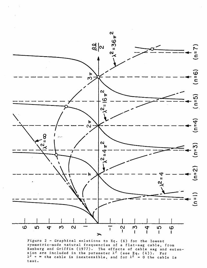
A graphical solution to Eq. (6) is presented in Fig. 2 for
several values of the parameter A2 • The arrows indicate the
Bivalues of z which correspond to the natural frequencies of a
taut string. For small >-2 the symmetric mode frequencies
A2approach those of a taut string. As increases, the first
symmetric mode frequency increases toward the first antisymmetric
A2frequency. They coincide for = 41f2 and thereafter the first
symmetric mode frequencyis greater than the higher antisymmetric
frequencies. At still larger values of A2 these frequency
crossovers occur at the higher symmetric modes.
A2As an example consider = 3611 2 • The antisymmetric mode
of Sivalues are given nn
n 2,4,6, etc. as before while2 by z·
the first four symmetric mode solutions are indicated by the
encircled intersections in Fig. 2. The lowest two symmetric mode
frequencies have crossed over and lie above the lowest two
antisymmetric frequencies. The frequencies of the third sym
metric and antisymmetric modes are equal (crossover is occuring)
while the fourth symmetric mode frequency is quite close to the n
= 7 frequency of a string. For the modes higher than n = 7 the
natural frequencies are essentially those of the taut string.
The catenary effects progress into the higher modes as A2

increases, but for finite >- 2 some unaffected modes remain.
Returning to the first symmetric mode frequency of the example,
there is little difference between >- 2 = 36ir2 and 1- 2 ="' so that
the first mode is nearly inextensible. For >- 2 + Eq. (6)00
reduces to
(11)
which is also plotted in Fig. 2. With this frequency equation
the symmetric natural frequencies are again well ordered and
alternate with antisymmetric frequencies, but there is a shift of
between Q.93 " and " in these symmetric mode frequencies with
respect to the taut string symmetric mode frequencies.
The mode shapes of a horizontal slack cable are affected by
the apparent frequency crossover in a complex manner. A sym
metric mode must possess an even number of nodes. Thus the mode
shape acquires two additional nodes in crossing over, and alters
its overall form while preserving symmetry. The transition is
smooth as shown in Fig. 3 which is adapted from a related numer
icpl simulation by West, Geschwindner and Suhoski (1975). A
dashed line which corresponds to the example >- 2 = 36,,2. is
included in Fig. 3(a). The related but more complex case of an
inclined slack cable is considered later in the report.
This section has summarized the linear solution derived by
Irvine and Caughey ( 1974) for the dynamics of slack cables with
/
/__ ----.p__
---<.D
- - - -...- II c:-
-- I{)---...-II
c:-------... 11
c:-(\I -I:::
--7-- ¢-------~ --...- II
~· ..< ------ -c:
.. ....
~ C\J
_ ..... II-¢II c:-~;-'-___ ._
- == ____ .......-_::;::---------- ... c:-I{) C\J !'() ¢ I{) <.D
I I I I I
Figure 2 - Graphical solutions to Eq. (6) for the lowest symmetric-mode natural frequencies of a flat-sag cable, from Ramberg and Griffin (1977). The effects of cable sag and extension are included in the parameter A2 (see Eq. (4)). For A + 00 the cable taut.
2 A2is inextensible, and for = O the cable is

A2=367T
2 1.60
t;3.0 I ...... t:: 1.50
C\J II
3 I (a) C\J
II31.40
~
>u ~2.0
~
>~ 1.30
::::> 0 w a:: LL.
<i 1.0 I I IL----,.
w ::::> @1.20 a:: LL.
<i 1. 10 a:: ::::> ti z
~SEE ENLA I IN FIGURE 3 b
a:: ::::>ti 1.00 z
00...___.__._._~_._~_._~~ 0.90 00 100 200 300 400 500
(b)
y/ '/
~
~u !:>U ru ~u l lU t
SAG TO SPAN RATIO, s/.D.
Figure 3 ~ Two figures adapted from West et al (1975) showing (a) the natural frequencies versus the variation in sag including modal crossovers for a cable with its ends at the same elevation, and (b) an indication of the mode shape transitions during a crossover of the lowest modes of Figure ](a).
SAG TO SPAN RATIO, s/.Jt
sag-to-span ratios of 1:8 or less. This is a special case of the
more general asymptotic perturbation solution for the linear
dynamics of taut and slack cables derived by Triantafyllou
(1984b), and discussed further by Bliek (1984).
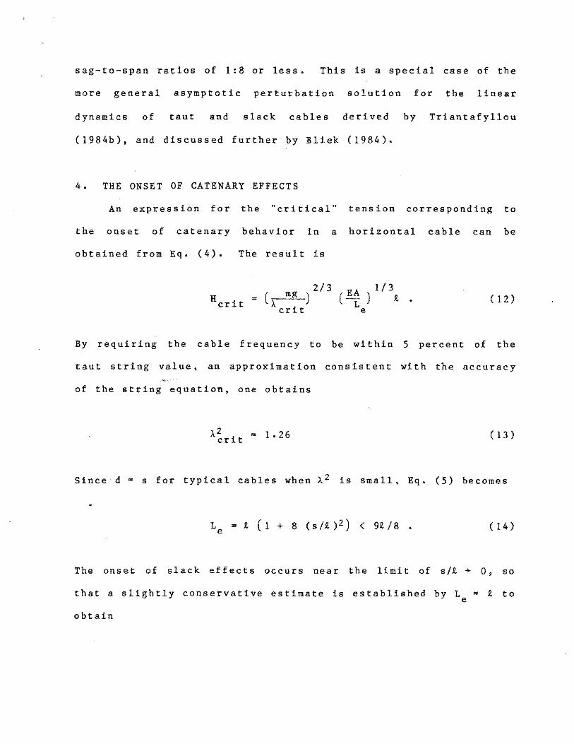
4. THE ONSET OF CATENARY EFFECTS
An expression for the "critical" tension corresponding to
the onset of catenary behavior in a horizontal cable can be
obtained from Eq. (4). The result is
2/3 EA 1/3 = ().. mg_) ( -i:: ) 9. ( 12)
cri t e
By requiring the cable frequency to be within 5 percent of the
taut string value, an approximation consistent with the accuracy
of the string equation, one obtains
)..~rit = 1.26 (13)
Since d ~ s for typical cables when J.. 2 is small, Eq. (5) becomes
Le=£ (1 + 8 (s/£)2 ) < 99./8. ( 14)
The onset of slack effects occurs near the limit of s/'l + O, so
that a slightly conservative estimate is established by L ~ £ to e
obtain

(15)
where W = mgi is the total weight of the cable to the accuracy of
the linear theory. The corresponding critical sag is
scrit = 0.134 (16)
It should be emphasized that this criterion applies to the
initiation of catenary effects in only the symmetric modes, since
the antisymmetric modes are unaffected for s/i < l :8 and R > w.
Furthermore, at H = Hcrit the only affected mode will be the n =
l mode. If one is interested in the onset of slack effects in
the higher symmetric modes, then the expression becomes
=(W2EA)l/3H (17 a)crit ,,2
n
,,2 a = 0.525 n 'fr, n = 1,3,5, etc .. (17b)n
Experimental results are discussed later in this report and in a
previous related paper and report which deal with marine cable
applications; see Ramberg and Griffin (1977), Griffin et al
(1981).
5. THE INCLINED SLACK CABLE
The linear theory just described has proven to be a valuable
tool in the analysis of marine cable vibrations. A shortcoming
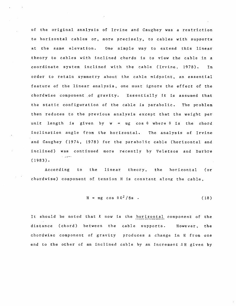
of the original analysis of Irvine and Caughey was a restriction
to horizontal cables or, more precisely, to cables with supports
at the same elevation. One simple way to extend this linear
theory to cables with inclined chords is to view the cable in a
coordinate system inclined with the cable (Irvine, 1978). In
order to retain symmetry about the cable midpoint, an essential
feature of the linear analysis, one must ignore the effect of the
chordwise component of gravity. Essentially it is assumed that
the static configuration of the cable is parabolic. The problem
then reduces to the previous analysis except that the weight per
unit length is given by = mg cos e where e is the chord
inclination angle from the horizontal. The analysis of Irvine,
and Caughey (1974, 1978) for the parabolic cable (horizontal and
inclined) was continued more recently by Veletsos and Darbre
(1983).
According to the linear theory, the horizontal (or
chordwise) component of tension H is constant along the cable,
H =mg cos ei2 /8s (18)
It should be noted that R. now is the horizontal component of the
distance (chord) between the cable supports. However, the
chordwise component of gravity produces a change in H from one
end to the other of an inclined cable by an increment AH given by

AH = mg Jl sin 6 (19)
Thus the modified linear analysis for inclinded slack cables is
subject to
£ = AH << l H
or
£ = 8 s tan e /£ << 1 ( 20)
This condition places rather stringent limits on the sag-to-span
ratio as the chord inclination angle steepens.
Triantafyllou ( 1984b) Triantafyllou and Bliek ( 1983), and
Bliek (1984) have developed asymptotic analytical solutions based
upon perturbation theory for the linear dynamics of taut and
sagged inclined cables. It was found from the analysis that the
most important parameter governing the cable dynamics was
m 2 ( m w2 )Q ( s) = M a 0 1 - ----·------ ( 21) EA a~ ( S)
d.p (s)0
where a = dS the local curvature, and M is the virtual0
(physical +added) mass of the cable. The parameter Q represents
the interaction between and relative importance of elasticity and
curvature effects for the inclined cable. The linear theory
developed by Irvine and Caughey (1974, 1978) for horizontal and
inclined cables represents the special case Q = constant. This

is the parabolic cable approximation, or a = constant together0
with the condition that the ratio of cable weight to tension,
is small. The solution obtained by Triantafyllou
consists of slow and fast varying terms with respect to the
distance along the cable. When Q(S) becomes zero at some point
along the cable, the slowly varying solution is of exponential
form up to the Q = 0 point and sinusoidal beyond it. This
transition corresponds to a change from inextensible cable
dynamics (exponential; curvature important) to taut cable
dynamics (sinusoidal: elasticity important). Over some length of
the cable there will be in general a combination of the two types
of behavior.
A frequency crossover never occurs in the case of the
inclined cable. Instead the modes are hybrid in form over the
transition range from the inextensible to the taut cable. They
are a mixture of symmetric and antisymmetric modes as shown by
Triantafyllou ( 1984b). There is virtually no difference in the
natural frequencies computed by the methods developed by
Triantafyllou and by Irvine (1978), as shown in Table 1, but the
hybrid mode shapes are unique in form as shown here in an example
given below.
2 The governing parameter A for the inclined cable is given
by (see Irvine, 1978)
H L ( _l_..!l) ( 22)
EA '
-------------
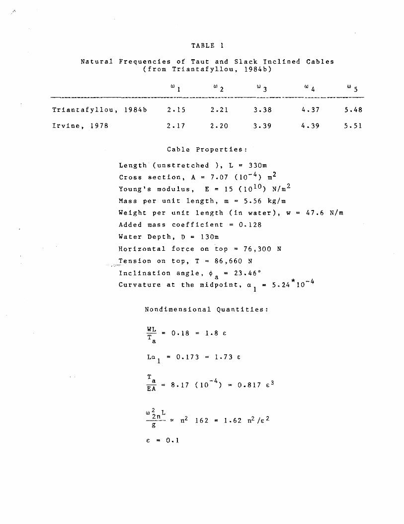
TABLE 1
Natural Frequencies of Taut and Slack Inclined Cables (from Triantafyllou, 1984b)
w 1 W2 W3 W4 W5
Triantafyllou, 1984b 2. 15 2.21 3.38 4. 3 7 5.48
Irvine, 1978 2. 1 7 2.20 3.39 4. 39 s.s1
Cable Properties:
Inclination angle, ~ = 23.46° a 4 Curvature at the midpoint, a = 5.24*10-
1
Nondimensional Quantities:
= 0. 18 = 1. 8 e
La = 0.173 = 1.73 e1
w2 L2n g
e = 0. 1
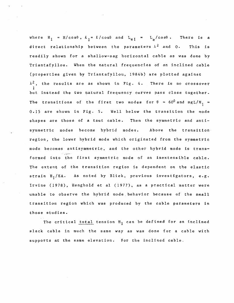
where H = L /cose. There is a 1 e
direct relationship between the parameters >. 2 and Q. This is
readily shown for a shallow-sag horizontal cable as was done by
Triantafyllou. When the natural frequencies of an inclined cable
(properties given by Triantafyllou, 1984b) are plotted against
>- 2 , the results are as shown in Fig. 4. There is no crossover 1
but instead the two natural frequency curves pass close together.
The transitions of the first two modes for 6 = 60° and mgL/H = 1
0.15 are shown in Fig. 5. Well below the transition the mode
shapes are those of a taut cable. Then the symmetric and anti
symmetric modes become hybrid modes. Above the transition
region, the lower hybrid mode which originated from the symmetric
mode becomes antisymmetric, and the other hybrid mode is trans
formed into the first symmetric mode of an inextensible cable.
The extent of the transition region is dependent on the elastic
strain H /EA. As noted by Bliek, previous investigators, e.g. 1
Irvine (1978), Henghold et al ( 1977), as a practical matter were
unable to observe the hybrid mode behavior because of the small
transition region which was produced by the cable parameters in
those studies.
The critical total tension H can be defined for an inclined1
slack cable in much the same way as was done for a cable with
supports at the same elevation. For the inclined cable.

2.30
2.20
2.10
2.00
2 1.90
1: e= 1° 2: e= 30°
3: e= 00°1.80
1.70 .____..____....___-1-___.._____..____.
25.0 30.0 35.0 40.0 45.0 50.0 55.0
A12
Figure 4 - The first two natural frequencies of an inclined slack cable in air versus the parameter A~, for mgL/H = 0.15 and for
1inclination angles of e = 1°, 300 and 600: from Triantafyllou (1984b).

MODE1 MODE2
l,2 = 7.4
/I \ SYMMETRIC ANTISYMMETRIC
25.2
34.0
40.0
54.8
69.6
81.4
I ANTISYMMETRIC
Figure 5 - The transition with increasing A\ of the first two natural modes of an inclined slack cable in air, for 6 = 600 and mgL/H = 0.15 as in Figure 4, from Triantafyllou (1984b).
1

2
cos2e) ,_ 1 ( H ~A ) I e I
(23)
and if the assumption once again is made that Lel~ 1- , then1
cos2e •
This equation can be rearranged into the form
2 (mg!. ) EA cos 2e
1(23a)
which becomes
( 24)
since W = mgt , is the total cable weight to the accuracy of the1
linear theory and again Ai = 1. 26 for the lowest symmetric (n=l)
cable mode. The antisymmetric modes are unaffected as before for
The onset of slack effects in the higher
2cables can be estimated by using Eq. ( 17b) to compute A 1 ,n
A major finding of the studies by Triantafyllou and Bliek
( 1983, 1984, 1984b) is that the dynamic: tension in the cable is
increased greatly over the hybrid mode transition range.
Previously, dynamic tension effects were thought to be minimal
for the antisymmetric modes, so that from a practical standpoint

fatigue and failure effects were only important for the symmetric
modes.
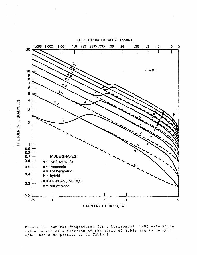
Figures 6, 7 and 8 depict the behavior of the frequencies
corresponding to the lowest eighteen modes for a suspended cable
possessing the physical properties defined in Table !. Figures 6 0
to 8 refer respectively to suspension inclinations of e = 0
(horizontal), 300 and 600. The results shown there independently
confirm the findings of Bliek (1984) and a Triantfyllou (1984b)
that in a strict sense, frequency crossover of the in-plane modes
occurs only for the special case of horizontally suspended cables
(Fig. 6) • whereas nonzero inclinations lead to a glancing
(hybrid) behavior of the frequency plots (Figs. 7 and 8). These
computations employed the method developed by Rosenthal ( 1981)
which was described earlier in the report.
In each of the figures the horizontal axis depicts the sag-
to-length ratio which ranges from near zero for taut cables to
slightly over one-half for a completely slack or doubled-up cable
whose end positions are made to coincide ("slightly over one-
half" because of the stretch induced by the cable's weight). All
inplane mode curves (which coincide with out-of-plane mode curves
over certain ranges) are shown as solid lines. Dashed lines
depict ranges over which only out-of-plane modes exist. The
chord-to-length ratios corresponding to these sag-to-length
ratios are also indicated and range from slightly greater than
one for a tautly stretched cable to zero for the doubled-up case.
CHORD/LENGTH RATIO, lcos8/L
1.003 1.002 1.001 1.0 .999 .9975 .995 .99 .98 .95 .9 .8 .5 0 20ro;;:"r....::--.-~...,-~-.~~---,:---r-~...,-~....--~-,~--,~-....~~..-~
a 2;,: (.)
z UJ ::::> 0 UJ a: u. 1
0.9 0.8 0.7 0.6
0.5
0.4
0.3
0.2 .005
e= 0°
.........:----~.s--..,. ..........
..... ..... ..... ...... .....
.....................
MODE SHAPES:
IN-PLANE MODES: s = symmetric a = antisymmetric h =hybrid
OUT-OF-PLANE MODES: o = out-of-plane
..... ..........
...... ...... ...... ...... ',o
...... ...... .....
.......... ..................
.01 .05 .1 SAG/LENGTH RATIO, S/L
G UJ (/)--0 <l'.a:
10 9 8 7 6 5
4
3
Figure 6 - Natural frequencies for a horizontal (8=0) extensible cable in air as a function of the ratio of cable sag to length, s/L. Cable properties as in Table 1.
.5

The vertical scale denotes the frequency w of all the
depicted modes in radians per second. Both the horizontal
(sag/length) and vertical scales are logarithmic to show the full
ranges of values. Except for very large sag and for the cross
over effects (or the comparable hybrid mode transition for the
inclined cases). these logarithmic frequency plots all exhibit a
distinct downward slope equal to -1/2. This is because the
frequency is approximately proportional to the square root of the
horizontal tension component H1 , while the tension itself is
approximately proportional to the sag.
Since the horizontally-suspended cable is a limiting special
case of suspension at an arbitrary angle of inclination, the
following discussion will be limited to the behavior of frequency
with sag as shown in Fig. 8, the case of 6 = 60° inclination.
In this figure we focus our attention respectively on the lowest
out-of-plane and the lowest in-plane modes, since higher pairs of
such modes possess characteristics which are similar to those of
the lowest pair.
We note that the lowest out-of-plane mode has a frequency
which is remarkably linear with sag, even out to the maximum sag
of slightly over one-half. This mode is the only one which
exhibits this high degree of linearity. The corresponding in-
plane frequency at the low-sag end begins to rise above the out
of-plane value and initially continues to exhibit an essentially
symmetric mode shape. This is the well-known lowest resonance of
a taut string. As its frequency rises towards the frequency of
the second out-of-plane mode, however, it loses its symmetry,
becoming "hybrid" as Bliek and Triantfyllou termed it.
As its frequency glances from the second in-plane mode
frequency (touching it in the horizontal case), it then remains
only sightly below the second out-of-plane mode, becoming
decidely anti-symmetric with increasing sag. For higher values
of sag, the first in-plane mode then lowers its frequency away
from the second out-of-plane value, and finally returns to where
the lowest pair again has two identical frequencies, which cor
respond to the pair of orthogonal pendulum modes at maximum sag,
i.e. a cable folded back along its length. The figure shows the
corresponding behavior for all of the nine pairs of out-of-plane
and in-plane modes which were computed as part of this study.
Bliek (1984) has compared results from the perturbation
theory (Triantafyllou, 1984) with a finite-difference solution
for the linear cable dynamics. An explicit centered-difference
scheme was selected to solve the problem by means of a transfer
matrix formulation. From the numerical simulation, which can be
considered as "exact", predictions of the dynamic tension, angle
of inclination, and tangential and normal displacements can be
obtained. The natural frequencies are dependent upon three
parameters:

20ro.;::-,......,..-.,.-~-,-~,..-.,-..,.-,-----,-~-.~.,-~.,.-~-.-~-.~-r~-r--r
10 ""-. 9 8 7 6
5
4G w en
30
'-.... '-.... '-....~°"- (:I= 30•
$
0 ........~ ·------,...... ..........
.......... ..........
<(a:-3
>-' u z w
@ ff
2
1 0.9 0.8 0.7 0.6
0.5
0.4
0.3
MODE SHAPES:
IN-PLANE MODES: s = symmetric a = antisymmetric h =hybrid
OUT-OF-PLANE MODES: o = out-of-plane
.......... ..........
.......... ',o
.......... ...........
.......... ..........
...........
0.2 ,__~~~..._~~~~~~~~--4~~~--''--~~~~~~~~--' .005 .01 .05 .1 .5
CHORD/LENGTH RATIO, lcos(:l/L
1.003 1.002 1.001 1.0 .999 .9975 .995 .99 .98 .95 .9 .8 .5 0
SAG/LENGTH RATIO. S/L Figure 7 - Natural frequencies for an inclined (6 = 30°) extensible cable in air as a function of the ratio of cable sag to length, s/L. Cable properties as in Table 1.

1.003 1.002 1.001 1.0 .999 .9975 .995 .99 .98 .95 .9 .8 0
10 9 8 7 6
5
4
3
2
e=60°
1 0.9 0.8 0.7 0.6 0.5
0.4
0.3
MODE SHAPES:
IN-PLANE MODES: s = symmetric a = antisymmetric h =hybrid
OUT-OF-PLANE MODES: o = out-of-plane
_....___________,
.1
G w (J).._ c <( a: 3
c· z
s w
w a: u.
0.2 .______.___________._____
.005 .01 .05
SAG/LENGTH RATIO, S/L
.5
CHORD/LENGTH RATIO, 1cos6/L
Figure 8 - Natural frequencies for an inclined (8 = 600) extensible cable in air as a function of the ratio of cable sag to length, s/L. Cable properties as in Table I, legend as in Figures 6 and 7.

0 the inclination angle' e ;a
o the non-dimensional weight, mgL/H 1 ·
o and, the elastic strain, H1 /EA.
Here H is the tension component H/cos e The latter two can1 a
be combined as shown earlier into the single fundamental
2parameter >. that characterizes the cable dynamics. As noted
earlier, AZ is proportional to the ratio of the elastic stiffness
to the catenary stiffness.
Some typical examples of the results obtained for an exten
sible cable in air by Bliek are shown in Figs. 9 to 11. A value
of (H 1 /EA)-l = 400 was employed in the calculations. This is
representative of a steel cable where the ratio of the elastic,
or longitudinal, and transverse wave speeds is ce 1/ctr = 20. The
numerical results were obtained with a centered difference scheme
using 100 inttlgration intervals over the length of the cable.
The natural frequencies of the firet two symmetric and
antisymmetric transverse modes are plotted in non-dimensional
o0form as a function of mgL/H for a horizontal cable (6 = ) and1
for an inclined cable ( e = 30°). The modal crossover is clearly
shown for the horizontal cable in Fig. 9 and the perturbation
theory and numerical results are in overall good agreement. When
the cable is inclined at e = 3o 0 there no longer is a frequency
crossover, but rather the hybrid mode transition as shown in
Fig. 10. The symmetric modes are transformed into antisymmetric
modes and vice versa as shown earlier in Fig. 5. Again there is
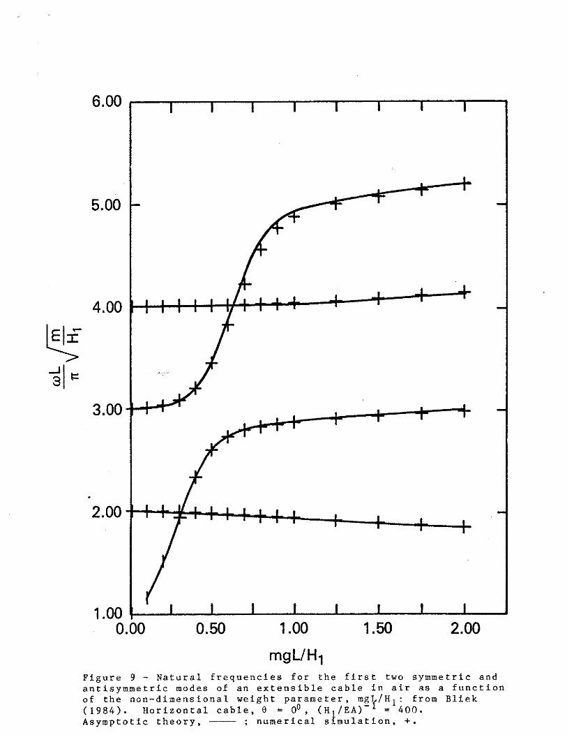
6.00
5.00
4.00
1.00 0.00 0.50 1.00 1.50 2.00
mgUH 1 Figure 9 - Natural frequencies for the first two symmetric and antisymmetric modes of an extensible cable in air as a function of the non-dimensional weight parameter, mgL/H 1 : from Bliek (1984). Horizontal cable, 8 = oO, (H 1 /EA)-l = 400. Asymptotic theory, -~- ; numerical simulation, +.

good agreement between the perturbation solution and the numer
ical simulation. The natural frequencies for the first pair of
modes are shown on an expanded scale in Fig. 11. This enlarge
ment demonstrates very clearly that no crossover exists. This
hybrid modal transition now has been demonstrated conclusively by
applying the perturbation solution (Triantafyllou, 1984b' Bliek,
(1984) and by means of independent numerical simulations by Bliek
and the present writers.
The results in Figs. 9 to 11 show the overall good agreement
between the two solution approaches. However, at large inclina
tion angles (e 600) and the very high values of the non-
dimensional weight mgL/H the perturbation solution diverges from1
the numerical simulation (Bliek, 1984). The agreement between
the two approaches improves at the higher cable modes where the
change in caole tension becomes smaller over a wavelength of the
vibration.
6. SLACK CABLES WITH ATTACHED MASSES
All of the results discussed thus far have been limited to
horizontal and inclined bare cables. However, there are many
marine applications where cables have arrays of instrumentation
modules, weights and buoyancy elements attached to them. The
computer code NATFREQ was developed at the California Institute
of Technology for the Naval Civil Engineering Laboratory to
provide a means for predicting the natural frequencies, mode

mass term affects only the transverse motions of the cable (in
plane and out-of-plane) and not the longitudinal or tangential
motions. Thus in order to derive a complete dynamic analysis of
a slack cable in water the natural frequencies of the transverse
modes must be corrected for the added mass effect of the fluid.
The elastic or tangential modes need not be corrected for the
fluid inertia or added mass. The mass of attached discrete
elements such as the cylindrical lumps discussed in the previous
section also must be corrected for the fluid inertia effect.
The dimensionless added mass coefficient Cam is defined by
( 26)
where mw is the virtual (physical + added) mass in water, mA is
the mass in air, and S is the specific gravity of the cable or
attached member. For a taut cable the natural frequencies in the
two media follow the relation
( 27)
Then the added mass coefficient is given by
( 28)

and can be derived from measurements of the natural
frequencies in air and in water. Ramberg and Griffin (1977) have
reported extensive measurements of the added mass of marine
cables by this method for the case of taut cables. Less
extensive measurements by Ramberg and Griffin of the natural
frequencies of slack marine cables in the two media suggested
that the added mass contribution was the same f'or slack and taut
2cables when the static effect of buoyancy on A was properly
accounted for in the crossover or hybrid response regime. In
most instances it is reasonable to assume that Cam = l; that is,
the added mass is equal to the volume of fluid displaced by the
cable or attached mass.
Hydrodynami5 Drag An important consequence of the resonant
cross flow oscillations of structures and cables due to vortex
shedding is an amplification of the mean in-line drag force (or
equivalently the drag force coefficient CD). The drag amplifi
cation measured prior to 1980 under a variety of conditions has
been reported by Griffin et al (1981). More recent and extensive
measurements of the drag on cables and cylinders in water are
discussed by Vandiver ( 1983), Griffin and Vandiver ( 1983) and
Griffin (1985). From all of these discussions it is clear that
vortex-excited vibrations of cables and cylinders in water can
cause amplifications in the hydrodynamic drag of up to 250
percent.
Two crucial elements in the accurate prediction of the
hydrodynamic drag on a vibrating cable are accurate estimates of
the natural frequencies and the mode shapes associated with the
vibrations. The frequency must be known in order to determine
whether the Strouhal frequency of vortex shedding will lock-on or
resonate with one or several of the natural frequencies of the
cable. The mode shape must be known in order to determine the
vortex-excited strumming pattern along the cable. Then the local
cross flow displacement amplitude distribution lengthwise along
the cable can be used to predict the overall hydrodynamic drag
from the local drag amplification.
The NATFREQ computer code described by Sergev and Iwan
(1980) by Griffin and Vandiver (1983) has the capability to
predict the strumming drag on a taut cable with or without
attached masses. In order to make a comparable strumming
assessment for a slack cable configuration, the natural
frequencies and mode shapes also must be known with some
accuracy. The methods described by Triantafyllou ( 1984), Bliek
( 1984), and in this report can be applied to the case of a bare
cable. For a slack cable with attached masses, the SLACK! and/or
SLACK2 computer codes can be used to predict the in-plane natural
frequencies and mode shapes which are influenced by the cable
strumming. The results discussed in the previous section clearly
show that for slack cables, accurate predictions are limited to
the lowest cable modes. Otherwise only a rough approximation is
possible. This is in contrast to the NATFREQ code, for which
Sergev and Iwan give an example showing the computed 16/nd mode
for a 4700 m (15400 ft) long taut cable with 380 attached masses.
8. SUMMARY
Conclusions. The linear theory for the dynamics of
horizontal cables with sag-to-span ratios of 1 :8 or less can be
described by the linear solution derived by Irvine and Caughey
(1974). This is a special case of the more general perturbation
solution for the linear dynamics of taut and slack cables derived
by Triantafyllou (1984b) and Bliek (1984). The dynamics of
horizontal slack cables are characterized by a frequency
"crossover" behavior. This modal crossover is a complex
phenomenon whereby three modes of the cable have the same natural
frequency. These modes include a symmetric in-plane mode, an
antisymmetric in-plane mode and an out-of-plane or sway mode.
A frequency crossover never occurs in the case of the
inclined cable. Instead the modes are hybrid in form over the
transition range from the taut to the inextensible cable
behavior. These natural modes are a mixture of symmetric and
antisymmetric modes as shown by Triantafyllou (1984b) and in this
report. There are virtually no differences in the natural
frequencies computed by the met hods of Triant afy l lou and Irvine
( 1978), but the mode shapes of the inclined slack cable are
unique in form as the natural frequencies pass close together but

never cross over. Several examples of both the crossover and the
hybrid mode behavior are given in this report.
The results obtained in this study have shown that for slack
cables with attached masses only the lowest cable modes can be
modelled with reasonable accuracy at the present time. Otherwise
only a rough approximation is possible. This is because of the
relatively small numbers of finite elements and integration
intervals which limit the present capabilities of the two codes.
The addition of attached masses to the bare cable affects both
the antisymmetric and symmetric in-plane modes. There is a
systematic increase in the natural frequencies of a slack cable
as masses are attached to it. For the symmetric modes the
natural frequency may increase or decrease, depending upon the
proximity to the crossover or hybrid regions of the cable
response. This is caused by the extreme sensitivity of the
symmetric cable modes to small changes in tension and sag near
those regions.
Recommendations. The capabilities of existing computer
codes are limited, as mentioned above, to calculating with
accuracy only the lowest cable natural frequencies and mode
shapes. The computations of the higher modes are rough
approximations because of the relatively small number of finite
elements or integration intervals that can be employed
efficiently on all but the largest computers. In order to make
practical engineering calculations of the dynamics of slack

cables with attached masses, more efficient solution routines and
means to employ the capabilities of existing medium size and
large-scale computing machines must be sought. The approach of
Rosenthal (1981) based upon Stodola's method of successive
approximations appears to be the more promising one for the case
of a cable with attached masses. Then the need to solve the
large matrix equations inherent in the finite element method is
eliminated, and the computational resources are greatly reduced.
For a bare cable either of the approaches described by
Irvine and Caughey (1974), Triantafyllou (1984b) or Bliek (1984),
or some combination of the three, should yield positive
results. Rosenthal's approach also is applicable to the special
case of the bare cable as shown previously and in this report.
The effects of added mass or fluid inertia are an important
consideration for the transverse (in-plane and out-of-plane)
modes of a cable in water. The longitudinal or elastic modes are
unaffected by the added mass of the fluid. Thus any improved and
more "user friendly" slack cable dynamics computer code should
account for the added mass effect on both the cable and any
discrete masses which are attached to it.
Two crucial elements in the accurate prediction of the
hydrodynamic drag on a vibrating marine cable are accurate
estimates of the natural frequencies and mode shapes of the
vibrations. This and other recent studies have demonstrated the
complexity of the slack cable dynamics problem. Thus an

assessment of the strumming behavior of a slack cable and of the
overall hydrodynamic drag presently is limited to the lowest
cable modes as described earlier. It is recommended that any
improved slack cable dynamics code also include the capability
ofpredicting the hydrodynamic drag. A similar capability is
available in the taut cable dynamics code NATFREQ described by
Sergev and Iwan (1980).
9. ACKNOWLEDGEMENTS
This study was conducted at NRL with funds provided by the
Technology Assessment and Research Branch of the Minerals
Management Service, U.S. Department of the Interior. The authors
are grateful to Dr. E.W. Miner of NRL for his much-needed advice
and assistance with the slack cable computations. Dr. S.E.
Ramberg of NRL wrote the original versions of Sections 3 and 4
and provided many useful comments on the complete report.

10. REFERENCES
A. Bliek, 1984, "Dynamics of Single Span Cables", Ph.D. Thesis, Massachusetts Institute of Technology.
M.L. Gambhir and B. de v. Batchelor, 1978, "Parametric Study of the Free Vibration of Sagged Cables", Computers & Structures, Vol. 8, 641-648.
O.M. Griffin, 1985, "Hydrodynamic Loads on Marine Risers and Cables Due to Vortex Shedding", NRL Memorandum Report, in preparation.
O.M. Griffin and J.K. Vandiver, 1983. "Flow-Induced Vibrations of Taut Marine Cables with Attached Masses", Naval Civil Engineering Laboratory Report CR 84.004; see also 1984. Transactions of the ASME, Journal of Energy Resources Technology, Vol. 106, forthcoming.
O.M. Griffin, S.E. Ramberg, R.A. Skop, D.J. Meggitt and S.S. Sergev, 1981, "The Strumming Vibrations of Marine Cables: State of the Art", Naval Civil Engineering Laboratory Technical Note N-1608.
W.M. Henghold and J.J. Russell, 1976, "Equilibrium and Natural Frequencies of Cable Structures (A Nonlinear Finite Element Approach)", Computers and Structures, Vol. 6, 267-271.
W.M. Henghold, J.J. Russell and J.D. Morgan, 1977, "Free Vibrations of a Cable in Three Dimensions, Proceedings of the ASCE, Journal of the Structural Division, Vol. 103, 1127-1136.
H.M. Irvine, 1978, "Free Vibrations of Inclined Cables", Proceedings of the ASCE, Journal of the Structural Division. Vol. 104, 343-347.
H.M. Irvine, 1981, Cable Structures, MIT Press' Cambridge.
H.M. Irvine and T.K. Caughey, 1974, "The Linear Theory of Free Vibrations of a Suspended Cable", Proceedings of the Royal Society of London, Series A, Vol. 341, 299-315, 1974· see also California Institute of Technology Dynamics Lab Report DYNL-108.
W.D. Ivan and N.P. Jones, 1984, "NATFREQ Users Manual - A Fortran IV Program for Computing Natural Frequencies, Mode Shapes and Drag Coefficients for Taut Strumming Cables with Attached Masses and Spring-Mass Combinations", Naval Civil Engineering Laboratory Report CR 84.026.

J .c. McGlothlin, 1982, "Drag Coefficients of Long Flexible Cylinders Subject to Vortex Induced Vibrations", M.S. Thesis, MIT Ocean Engineering Department.
A.G. Pugsley, 1949, "On the Natural Frequencies of Suspension Chains", Quarterly Journal of Mechanics and Applied Mathematics, Vol. 2, 412-418.
S.E. Ramberg and O.M. Griffin, 1977, "Free Vibrations of Taut and Slack Marine Cables", Proceedings of the ASCE, Journal of the Structural Division, Vol. 103, 2079-2092.
S.E. Ramberg and C.L. Bartholomew, 1982, "Vibrations of Inclined Slack Cables", Proceedings of the ASCE, Journal of the Structural Division, Vol. 108, 1662-1664.
J.H. Rohrs, 1851, "On the Oscillations of a Suspension Chain", Transactions of the Cambridge Philosphical Society, Vol. 9, Part 3' 379-398.
F. Rosenthal, 1981, "Vibrations of Slack Cables with Discrete Masses", Journal of Sound and Vibration, Vol. 78, 573-583.
E.J. Routh, 1955, Advanced Dynamics of Rigid Bodies, Sixth Edition, Dover: New York: original published in 1868.
D.S. Saxon and A.E. Cahn, 1953, "Modes of Vibration of a Suspended Cable", Quarterly Journal of Mechanics and Applied Mathematics, Vol. 6, 273-285.
S.S. Sergev and W.D. Iwan, 1980, "The Natural Frequencies and Mode Shapes of Cables with Attached Masses," Naval Civil Engineering Laboratory Technical Note N-1583• see also 1981, Transactions of the ASME, Journal of Energy Resources Technology, Vol. 103, 237-242.
A. Simpson, 1966, "Determination of the inplane natural frequencies of multispan transmission lines by a transfer matrix method", Proceedings of the Institution of Electrical Engineers, Vol. 113, 870-878.
R.A. Skop and G.J. O'Hara, 1970, "The method of imaginary reactions: a new technique for analyzing cable systems", Marine Technology Society Journal, Vol. 4, 21-30.
R.A. Skop and F. Rosenthal, 1982, "Method of Imaginary Reactions for Taut Cables", Proceedings of ASCE, Journal of the Structural Division, Vol. 108, No. ST7, 1669-1671.

A. I. Soler, 1970, "Dynamic response of a single cable with initial sag", Journal of the Franklin Institute, Vol. 290, 377-387.
W.T. Thomson, 1965, Vibration Theory and Applications, Prentice Hall: Englewood Cliffs, NJ; see -Chapter VII.________
M.S. Triantafyllou, 1982, "Preliminary Design of Mooring Systems", Journal of Ship Research, Vol. 26, 25-35.
M.S. Triantafyllou, 1984a, "Linear Dynamics of Cables and Chains", The Shock and Vibration Digest, Vol. 16, No. 3, 9-17.
M.S. Triantafyllou, 1984b, "The Linear Dynamics of Taut Inclined Cables", Quarterly Journal of Mechanics and Applied Mathematics. Vol. 37, 421-440.
M. S. Triantafyllou and A. Bliek, 1983, "The Dynamics of Inclined Taut and Slack Marine Cables", Offshore Technology Conference Preprint OTC 4498.
A.S. Veletsos and G.R. Darbre, 1983, "Free Vibrations of Parabolic Cables", Proceedings of the ASCE, Journal of Structural Engineering, Vol. 109, 503-519.
H.H. West, L.F. Geschwindner and J.E. Suhoski, 1975, "Natural Vibrations of Suspension Cables", Proceedings of the ASCE, Journal of the Structural Division, Vol. 101, 2277-2291.
H.H. West, J.E. Suhoski and L.F. Geschwindner, 1984, "Natural Frequencies and Modes of Suspension Bridges", Proceedings of the ASCE, Journal of Structural Engineering, Vol. 110, 2471-2486.

5.00
1.00 .__--JL...-.--1---'----L---'--_..__ __,__ __.__ __.
0.00 0.50 1.00 1.50 2.00
mgL/H1 Figure 10 - Natural frequencies for the first two symmetric and antisymmetric modes of an extensible cable in air as a function of the non-dimensional weight parameter, mgL/h , from Bliek
1(1984). Conditions as in Figure 9 except that the inclination angle e = 300.

2.20
2.10
2.00
1.90
1.80
1.70 0.30 0.32 0.35 0.37 0.40
mgl/H1
Figure 11 - An expanded plot of the hybrid modal transition zone for the first symmetric and anti-symmetric modes in Figure 10.

shapes and drag coefficients for taut cables with large numbers
of attached discrete masses. A basic description of the code and
an operating manual to aid in its use are available· see Sergev
and Iwan ( 1980), and Iwan and Jones ( 1984), respectively. An
extensive program of field experiments was conducted to benchmark
the capabilities of the NATFREQ code, and a comparison of the
code predictions and the results of the experiments has been
given by Griffin and Vandiver (1983, 1984).
In this section of the report a comparison is presented of
two computer codes which have been developed for predicting the
natural frequencies and mode shapes of slack cables with arrays
of discrete masses attached to them. This is a preliminary
assessment since the capabilities of the codes presently are not
as extensive and well-documented as are those of the taut-cable
code NATFREQ, and the solution algorithms for the slack cable
dynamics are far more complex than are those required for the
analysis of taut cables.
The two slack cable codes discussed here are called SLACK!
and SLACK2, respectively. SLACK! is essentially the three-
dimensional cable dynamics code which was developed by Henghold,
Russell and Morgan ( 1977) and modified later at NRL. The finite
element formulation employed in SLACK! is described in detail by
Henghold and Russell (1976). Three-node elements are employed in
the code which is capable of accommodating up to sixty nodes
along the length of the cable. SLACK2 is the most recent version

of the three-dimensional cable dynamics code developed at NRL by
Rosenthal (1981). This latter code uses a modified form of the
method of imaginary reactions described by Skop and O'Hara (1970)
and by Skop and Rosenthal (1982) to obtain the static cable
configuration. Then Stodola's method (see Thomson, 1965) is used
to calculate the cable dynamics. Stodola's method is a
successive approximation approach to computing the natural
frequencies and mode shapes of the cable. The use of Stodola's
method eliminates the need to solve the large matrix equations
which are inherent in the finite element method of computing the
natural frequencies. Up to sixty integration intervals can be
included over the length of the cable at the present time.
Details of the computational scheme are given by Rosenthal
( 1981). Both computer codes are capable of predicting the out
of-plane and in-plane components of the cable dynamic response.
The present discussion is limited to the transverse component of
the response since the longitudinal, or elastic, component occurs
at higher frequencies and is smaller by an order-of-magnitude.
The cable configurations chosen for the comparison and
deraonstration are slack cable analogues to the taut cable field
test set-up which was employed in the NATFREQ code validation.
At the test site a 22.9m (75 ft) long by 3.2 cm (!.25 in)
diameter taut cable was employed, so that for the present
computations the chord length was set equal tot = 22-9 m
(75 ft). The attached masses were cylindrical lumps of PVC into

which lead inserts could be put in order to change the physical
mass from "light" (m = 2 kg or 4.4 lbm) to "heavy" (m = 4.5 kg or
In the computations discussed below the cylindrical
masses are treated as point concentrated loads. This approxi
mation also is made in the NATFREQ taut cable code. Complete
descriptions of the cable, the attached masses, and the test set
up and instrumentation are given by McGlothlin ( 1982) and by
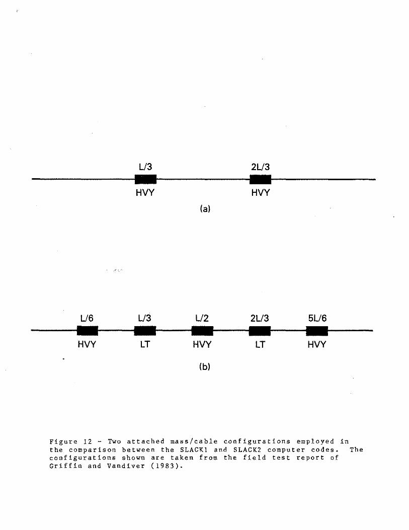
Griffin and Vandiver ( 1983). The two configurations chosen for
the computations are shown in Fig. 12. The first consists of two
evenly-spaced heavy masses. The second consists of five evenly-
spaced masses two light cylinders and three heavy cylinders.
The cable had a mass per unit length m = 1.14 kg/m (0.77 lbm/ft)
in air and an elastic stiffness EA= 8.9 x l0 5 N (2xl05 lb).
Since the relative capabilities of the two codes were not
known for the case when masses were attached to the cable. a
baseline comparison was made using just the hare cable. Then the
relative accuracies can be compared with the results obtained by
Rosenthal ( 1981). The present results are given in Table 2 for
the first nine cable modes. Twelve elements and twenty-five
nodes were used for the SLACKl finite element computations while
for the SLACKZ computations by Stodola's method thirty integra
tion intervals were used. These conditions were thought to be
reasonably comparable. The two methods give estimates of the
natural frequencies, in the proper order, which differ by less
than five percent for the first nine cable modes. For higher
----------------------U3 2U3
HVY HVY (a)
U6 U3 L/2 2U3 5U6
HVY LT HVY LT HVY
(b)
---
Figure 12 - Two attached mass/cable configurations employed in the comparison between the SLACKI and SLACK2 computer codes. The configurations shown are taken from the field test report of Griffin and Vandiver (1983).

modes the estimated frequencies diverge rapidly due to the
relatively limited number of elements used. The maximum
permissible number of finite elements is dependent on the
magnitude of the relative elastic stiffness AE/mgt due to the
nature of the governing equations for the natural frequencies and
the matrix manipulation routines that are used in the SLACK!
code.
The static solutions obtained by the two methods for all of
the slack cable configurations are virtually indistinguishable,
both for the bare cable and the cable with attached masses. The
maximum sag-to-length ratios, s/L, obtained by the two approaches
are compared in Tables 2, 3 and 4. These and the comparisons
which follow are for a cable deployed in air where added mass
effects are not important. A brief discussion of the effects of
added mass o~ the natural frequencies of a slack marine cable is
given in the next section of the report.
The natural frequencies obtained for the two cable-attached
mass configurations are compared in Tables 3 and 4. The results
for the cable with two evenly-spaced attached masses are listed
in Table 3 for the first nine natural cable modes. Eighteen
finite elements were employed for the SLACK! computations, while
two cases of fourteen and thirty integration intervals were
employed for SLACK2. In each case the sequence of modes was
properly ordered, i.e. out-of-plane, antisymmetric, etc. The
mode order shown is typical of relatively large sag-to-length

TABLE 2
Natural Frequencies of Horizontal Slack Cables ' (No Attached Masses)
Uniform Cable, AE/mg& = 3500: Chord-to-Length, l/L • 0.987
O, A, S = out-of-plane, in-plane antisymmetric and symmetric modes
Frequency, w (rad/sec) SLACK! SLACK2
Finite elements Stodola's method Mode Type (12 elements, 25 nodes (30 integration intervals)
------- ------·--·-----------------·----------------------------------------------·--0 2.706 2.706
A 5.317 5-282
o 5.421 5.389
s 7-728 7. 612
0 8. 160 8.060
A 10.971 10.660
0 10.983 10.710
s 13.584 12.970
0 13.884 13.332
Maximum sag-to-length, s/L = 0.0716 0.0714
ratios to the right of the modal crossover or hybrid mode
region. For this condition the cable exhibits largely inexten
2si ble behavior; that is, >. is large. For the cable deployed
2during the field tests, >. ~ 650 for ii,/L = 0.987 and
EA/mg ii, = 3500.
It can be seen from Table 3 that the results obtained with
the two computer codes for the cable with attached masses differ
more than the comparable bare cable results. The out-of-plane
first mode frequency computed using SLACK! is ten percent higher
than the same frequency computed using SLACK2. The solutions
obtained with the two codes diverge still further until for the
ninth mode the SLACKl-predicted frequency is eighteen percent
higher than the SLACK2 prediction. When the number of integra
tion intervals is reduced by one-half, there is only a three
percent decrease in the SLACK2 prediction of the ninth-mode
frequency. It was found in an earlier study (Rosenthal, 1981)
that the SLACK! code predictions tended to overestimate the
higher mode frequencies due to artificial stiffness effects upon
the finite element solution when the number of elements was too
few. Conversely, the SLACK2 prediction tended to underestimate
the true natural frequencies when too few integration intervals
were used. Thus the predicted frequencies are only true
estimates for the lowest cable modes. When the number of finite
elements or integration intervals is of the order of the mode
number, the predicted frequencies are only rough approximations.

---------
TABLE 3
Natu'ral Frequencies of Horizontal Slack Cables (Two Attached Masses)
Uniform Cable, AE/ mg~ = 3500; Chord-to-Length, t/L = 0.962
O, A, S = out-of-plane, in-plane antisymmetric and symmetric modes
-------·---------Frequency, w (rad/ sec)
SLACKl SLACK2 Finite elements Stodola's method
Mode Type (18 elements, 37 nodes) (30 intervals) (14 intervals)
0 2.231
A 4.172
0 4.416
s 7 . 2 51
0 7.496
A 8.969
0 9. 150
s 11.ot,3
0 11.361
Maximum sag-to-length, s/L 0. 120
2.021
3.688
3.877
7.038
7. 357
8.349
8.464
9.675
9.821
0 .119
2.020
3.674
3.861
6.959
7. 271
8.205
8.312
9.408
9.547
0. ll 8

The natural frequencies for the cable with five attached
masses are compared in Table 4. The mode type and ordering of
both the SLACK! and SLACK2-calculated frequencies are correct for
all nine modes. However, the frequencies predicted by the SLACK!
code again are consistently higher than the corresponding SLACK2
predictions. The first out-of-plane mode frequency is thirteen
percent higher and this difference increases to eighteen percent
for the eighth symmetric mode. Once again the static solutions
obtained by the two methods are virtually indistinguishable.
There is a general increase in the natural frequency of a given
mode as the number and mass of the attached bodies are
increased. This is opposite to what is found for an extensible
taut cable. There also is an increase in the sag-to-length
ratio s/L as the attachments on the cable are increased in
number.
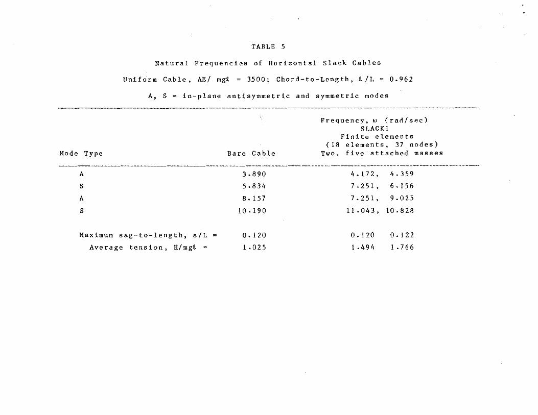
The first four in-plane mode frequenci~s for the three cable
configurations discussed here are compared in Table 5. It is
seen from the results that the increase in frequency is
systematic for the antisymmetric modes. For the symmetric modes
the natural frequency first increases relative to the bare cable
when two eq uall y-s paced mass es are attached to the cable. Then
the frequency decreases slightly when the number of attached
masses is increased to five. This behavior is caused by the
extreme sensitivity of the symmetric cable modes to small changes
in tension and sag near the crossover or hybrid regions of the

TABLE 4
Natural Frequencies of Horizontal Slack Cables (Five Attached Masses)
Uniform Cable, AE/ mg.!. = 3500: Chord-to-length, R./L = 0.962
O, A, S = out-of-plane, in-plane antisymmetric and symmetric modes
Frequency, w (rad/sec) SLACK! SLACK2
Finite elements Stodola's method Mode Type (18 elements, 37 nodes) (36 intervals)
0
A
0
s 0
A
0
s 0
2.326
4,359
4.624
6. 156
6. 590
9.025
9.257
10.828
11.402
2.061
3.832
4.047
5.226
5.506
7.816
7.892
9. I 7 2
9.240
Maximum sag-to-length ratio, s/L = 0. 12 2 0. I 2 2

cable response. The increase in static tension caused by the
addition of the attached masses is given in Table 5 for the three
cases.
The shapes of the fourth and eighth symmetric modes for the
cable with five attached masses are plotted in Fig. 13. The
predictions were made with the SLACK2 code. In each case the
vertical scale is normalized by the factor
I/ 2 (25)
The integrand is discontinuous at the locations of the individual
attached masses, leading to a Stieltjes integral representation
consisting of a regular integral representing the bare cable and
a sum of discrete mass terms (Rosenthal, 1981). It is clear from
the plotted mode shapes that in general the masses are in motion
and do not lie at nodes of the vi brat ion pattern. This is
similar to the findings of Griffin and Vandiver (1983, 1984) for
the case of taut marine cables.
7. ADDED MASS AND HYDRODYNAMIC DRAG
Added Mass. The effect of a dense fluid such as water on
the cable dynamics is an important consideration in terms of the
added mass, or fluid inertia, component of the hydrodynamic force
system. The total, or virtual, mass of the cable in water then
is the sum of the physical mass and the added mass. The added
----------
TABLE 5
Natural Frequencies of Horizontal Slack Cables
Uniform Cable, AE/ mgt = 3500: Chord-to-Length, R, /L = 0.962
A, S = in-plane antisymmetric and symmetric modes
Frequency, w (rad/sec) SLACK!
Finite elements (18 elements, 37 nodes)
Mode Type Bare Cable Two, five attached masses
A 3.890 4.172, 4. 359
s 5.834 7.251' 6. 15 6
A 8. 15 7 7.251, 9.025
s 10. 190 11.043, 10.828
Maximum sag-to-length, s/L = 0. 120 0. 120 0. 122
Average tension, H/mgt = 1 • 0 2 5 1 • 49 4 1 • 7 6 6

1.0
0.5 1.0a: S/L--"' "'
(a)-1.0
1.0
-1.0 (bl
Figure 13 - Normalized displacement patterns for the first two symmetric modes of the slack cable with five attached masses. Chord-to- length, 9./L = 0.962: elastic stiffness, AE/mgi = 3500.