the dynamics of legged locomotion in heterogeneous terrain...
TRANSCRIPT

The dynamics of legged locomotion inheterogeneous terrain: universality in scattering and
sensitivity to initial conditionsFeifei Qian and Daniel I. Goldman
Georgia Institute of TechnologyAtlanta, Georgia 30332–0250
Abstract—Natural substrates are often composed of particu-lates of varying size, from fine sand to pebbles and boulders.Robot locomotion on such heterogeneous substrates is compli-cated in part due to large force and kinematic fluctuationsintroduced by heterogeneities. To systematically explore howheterogeneity affects locomotion, we study the movement ofa hexapedal robot (15 cm, 150 g) in a trackway filled with∼ 1 mm “sand”, with a larger convex “boulder” of variousshape and roughness embedded within. We investigate how thepresence of the boulder affects the robot’s trajectory. To doso we develop a fully-automated terrain creation system, theSCATTER (Systematic Creation of Arbitrary Terrain and Testingof Exploratory Robots), to control the initial conditions of thesubstrate, including sand compaction, boulder distribution, andsubstrate inclination. Analysis of the robot’s trajectory indicatesthat the interaction with a boulder can be modeled as a scattererwith attractive and repulsive features. Depending on the contactposition on the boulder, the robot will be scattered to differentdirections after the interaction. The trajectory of an individualinteraction depends sensitively on the initial conditions, but re-markably this dependence of scattering angle upon initial contactlocation is universal over a wide range of boulder properties.For a larger heterogeneous field with multiple “scatterers”, thetrajectory of the robot can be estimated using a superpositionof the scattering angles from each scatterer. This scatteringsuperposition can be applied to a variety of complex terrains,including heterogeneities of different geometry, orientation, andtexture. Our results can aid in development of both deterministicand statistical descriptions of robot locomotion, control and pathplanning in complex terrain.
I. INTRODUCTION
Rocky, loose substrates are common in environmentsthat exploratory robots must traverse; such terrains cancontain granular media (GM) with particle sizes spanningmany orders of magnitude. When robotic locomotors travelacross these “flowable” types of heterogeneous terrain,they exhibit characteristic failure modes (slips, unstablefoot-holds, impassable barriers, course deviations, orlimb/tread fluidization of a thin layer of smaller particles)which significantly affect robot stability, maneuverabilityand power consumption. One of the major challenges increating the next generation of mobile robots is expandingthe scope of terramechanics [1][2] from large tracked andtreaded vehicles on homogeneous ground to arbitrarilyshaped and actuated locomotors moving on and withincomplex heterogeneous terrestrial substrates, to create a“terradynamics” [3] (in analogy to hydro and aerodynamics
which provide predictive power for aquatic and aerialvehicles) of locomotion on heterogeneous ground. However,in typical heterogeneous environments, the force fluctuationsintroduced by heterogeneities (gravels, rocks, boulders, etc.)during intrusion and drag can be large, which makes theapplicability of continuum terramechanics [1][2] unclear.Currently, most terrestrial vehicles (including mobile robots)are tested on substrates made of standardized homogenousmedia (e.g. Ottowa sand [4], lunar simulants [5]), while robotlocomotion on heterogeneous granular ground is relativelyunexplored.
Modelling and controlling robot locomotion onheterogeneous granular terrain requires fundamentalunderstanding of the complex interactions between therobot and the ground. This interaction can be especiallycomplicated when obstacles possess mobility relative to thesubstrate underneath (e.g., boulders/rocks can rotate, tilt,shift on or even sink into the fine sand). Multiple types ofinteractions – robot with the fine sand [3], robot with themulti-shaped boulders/rocks, as well as boulders/rocks withthe fine sand – must be considered, and the mobility of theboulders/rocks can dynamically change the terrain profileduring the interaction. Studying the response of a locomotoron heterogeneous granular terrain will generate a betterunderstanding of such interactions, and this understandingcan provide a predictive guidance in navigation planning.Most traditional navigation planning methods involve findinga collision free path, which requires the robot to avoidobstacles. For example, the potential field method (PFM) [6]treats obstacles as repulsive potentials that repel the robot.This is legitimate for most wheeled/treaded robots whichmust circumvent obstacles, but for legged robots, traversingobstacles by stepping over or upon them [7] can be anotheroption. Allowing robots to interact with obstacles [8], oreven manipulate the locomotion environment [9], couldsignificantly expand viable exploration space for obstacle-filled environments. Such advances in robot mobility willalso require a statistical terradynamics framework forlocomotion and control, in which deterministic understandingof robot-heterogeneity interactions can be used as inputs.A statistical terradynamics will allow robots to evaluateobstacle traversability and predict the probability of outcomes

(e.g., possible failure, trajectory deviation, etc.) of differentlocomotion modes. In this manner robots could chooselocomotion maneuvers to traverse challenging terrain, orperform successful anticipatory control [10] before thedisturbance to avoid fatal failure and course deviation.
To begin to create a terradynamic framework for leggedrobot locomotion on heterogeneous flowable substrates, wepreviously designed and constructed a SCATTER system [11](Systematic Creation of Arbitrary Terrain and Testing ofExploratory Robots) to automatically create heterogeneousgranular ground conditions and perform robot locomotiontests. In this paper we use SCATTER to study the robot’slocomotion on a diversity of heterogeneities, searching forprinciples that will allow us to move toward a terradynamicsof heterogeneous granular media. We find that the complexinteraction between the robot and a single boulder can bemodelled as a scattering process – each interaction willcause the robot to leave the boulder with a certain angle oftrajectory deviation, as if the robot was scattered. The formof the scattering process is sensitive to initial conditions ofthe robot but is insensitive to boulder shape and texture.As an initial step toward the heterogeneous terradynamics,we largely focus on single localized scatterers, but discusstoward the end of the paper the applicability of these resultsto robot locomotion on more complex heterogeneous fieldswith arrays of scatterers.
II. SYSTEMATIC CREATION OF ARBITRARY TERRAIN ANDAUTOMATED TESTING OF ROBOT LOCOMOTION
Natural heterogeneous granular terrains vary in particlesize, shape, compaction, orientation, etc., making exhaustivetesting of all terrain types impossible. In our study, we use amodel substrate – a bi-dispersed granular test bed filled with∼ 1 mm diameter poppy seeds (the simplified “sand”) withlarger particles (the simplified “boulders”) of various shapesembedded within – to control and vary terrain parameters.The relatively simple geometry and configuration of themodel terrain makes it feasible to create repeatable states ofgranular media with controlled heterogeneity, and facilitatesa systematic exploration of heterogeneous ground properties.
To precisely control terrain parameters, and tosystematically investigate robot locomotion on a varietyof heterogeneous granular terrains, we previously developeda fully-automated terrain creation which we call SystematicCreation of Arbitrary Terrain and Testing of ExploratoryRobots (SCATTER [11], Figure 1A) apparatus. UsingSCATTER, properties of heterogeneous multi-componentsubstrates such as compaction, orientation, obstacleshape/size/distribution, and obstacle mobility within thesubstrate, can be precisely controlled and varied to emulate awide range of natural terrain properties.
The central structure of the SCATTER system consistsof a 122 cm long, 51 cm wide air fluidized bed trackway(Figure 1B). Four vacuums (RIDGID, 16 gallon) are connectedbelow the trackway, forcing air through a flow distributer(0.635 cm thick, 50 µm pore size porous plastic) to evenlyfluidize the fine grains in the trackway, allowing controlof the compaction and creation of repeatable homogeneousgranular states of the fine grains. We used 1 mm diameterpoppy seeds as the model fine grains in this study, but thisground stiffness control technique can be applied to a largevariety of granular media, with particle diameter ranging fromhundreds of microns to a few millimeters. The resistance ofthe granular substrate created using this method is highlyrepeatable, and could be varied over a large range, fromgreater than that of close packed compaction states [12] toa zero resistance state [13]. Also, as previously measured inintrusion tests, the results obtained using these model granularsubstrates can be applied to more complex natural granularmedia composed of grains with greater polydispersity andangularity [3].
The entire trackway is supported by an aluminum tiltablesupport framing actuated by two linear actuators (Firgelli,454 kg load, 61 cm stroke) such that the trackway cantilt to create inclined/declined granular environments. Bycontrolling the extruded length of the linear actuator, thesubstrate inclination angle could be varied to more than 40◦,exceeding the maximum angle of stability [14] for mostgranular media used in locomotion studies [15][3].
(A) (B)
(C)
Gripper
Air �lter
servo
vacuum
tubing
(D)
Hall-e!ect
sensor
C-legs 1 cm
Fig. 1. Automated terrain creation and locomotion testing system. (A)The automated system, including the vision system, the 3-axis motor, theuniversal jamming gripper, the air fluidized bed and the tilting actuators. (B)Mechanical drawing of the automated system: a 3-axis motor mounted on atiltable trackway. (C) The universal jamming gripper lifting the robot. (D)The model locomotor, a small hexapedal robot (15 cm, 150 g).
To generate states of arbitrary heterogeneity, a 3-axis motorsystem (Copley, STA25, STB25, XTB38) was installed abovethe trackway, enabling the motor end-effector to move inthree dimensions. The motor end-effector drives a universaljamming gripper [16] (Figure 1C) to programmed locations,allowing for the creation of arbitrary distributions of boulders.The customized gripper assembly includes a balloon filledwith granular material (a “universal jamming gripper” [16]),a support frame, and a HI-TEC servo motor (HSR-5980SG).The 3D-printed support frame connects the gripper to vacuumtubing through an air filter, enabling the granular material inthe gripper balloon to switch between fluid-like and solid-likeproperties. The fluid-like property of the granular mediainside the balloon (when suction is off) allows the gripper todeform around the robot or boulders, while the solid propertyof the granular material (when suction is applied) enables thegripper to reach a jammed state, resulting in a rapid grippingof objects of complex shapes.
The gripper can grasp objects with large variation ingeometries (spheres, polyhedrons, cylinders, etc.), sizes(as long as the gripper membrane can reach sufficientlyaround the sides of the target [16], ≈ 50% ± 20% balloondiameter), and weights (up to 0.2 kg for the size of ourgripper). Using the universal jamming gripper, a large varietyof ground heterogeneities (boulders, rocks, logs, etc.) aswell as small scale robots can be automatically distributedand retrieved to produce different heterogeneous groundconfigurations and locomotor initial conditions. The grippersupport frame also provides an attachment from the gripperballoon to the servo disk, enabling the gripper assembly toadjust the orientation of the boulder and the robot for each test.
We used a small hexapedal robot (15 cm, 150 g,Figure 1D) as a simplified model locomotor to performlaboratory experiments. The robot has six 3D-printed C-shaped legs and uses a bio-inspired alternating tripod gait.The gait frequency of the robot was controlled by a DCmotor (Micromo 1724-SR with IE2-1024 encoder) usingpulse width modulation (PWM). A Hall-effect sensor wasattached on the robot body to control the initial leg phaseand to track leg tip positions during the run. We use thissmall RHex-like [17] robot as a model locomotor to performsystematic study with variation in leg shape, leg roughness,gait frequency, etc., and to discover interaction principles thatcan be further expanded to other legged locomotors.
Kinematic information of the robot, including the x, y, zcenter of mass (CoM) position as well as the yaw, pitch,and roll angle, was obtained by tracking three IR-reflectivemarkers attached to the robot using three top-view cameras(Naturalpoint, Flex13, 120 FPS). The cameras also monitoredthe location of the robot and the boulders before and aftereach test. This information was communicated to the motorsystem, so that the gripper could retrieve both the robot andboulders. The system also recorded dorsal and lateral high
speed reference videos that synchronized with the trackingdata.
All functions of the SCATTER system were controlledby a single integrated LabVIEW program. The system cancurrently perform more than 200 locomotion tests in one day,without human intervention, allowing comprehensive andsystematic exploration of effects of arbitrary heterogeneityand spatial distribution on interaction modes and performance.Using this system, we can investigate a variety of terrainand locomotor parameters, including sand resistance, bouldergeometry/texture/orientation, heterogeneity distribution,substrate inclination, as well as robot leg shape, foot sizeand gait frequency, etc.. We first discuss robot locomotionduring interaction with a single boulder, and then extend thisto large, multi-boulder fields.
III. SINGLE BOULDER INTERACTION ANALYSIS
Previous studies revealed that even on simplified bi-disperseheterogeneous granular ground robot locomotion exhibitedchaotic dynamics and multiple robot-ground interactionmodes [11]. The robot could slip on the top of a deeplyburied boulder, push a lightweight boulder to yield towardsthe side or into the sand, become stuck on the top of alarge boulder, or force a high-friction boulder to rotate inplace. The complexity of the observed interactions, evenin the simplified substrates, prompted us to concentrate onan even simpler model system. Therefore we began with asingle boulder interaction study to systematically analyze howdifferent boulder properties and robot kinematics affectedrobot-boulder interaction modes and robot locomotionperformance.
A. Experimental setup
We analyzed the interaction between the robot and a singleboulder buried in the sand, and the resulting robot CoMtrajectories. The boulder size was chosen to be 4 − 5 cm indiameter, comparable with robot C-leg diameter (3 − 4 cm),such that the boulder had a significant effect on robotlocomotion and had enough exposed area to distinguish leg-boulder contact positions, but was not a barrier too high forthe robot to traverse. We tested robot interactions for differentboulder properties varying boulder shape, orientation, andtexture. We also tested robot interactions with both immobileboulders (i.e., the boulder was fixed at a certain burial depth)and free boulders (i.e., the boulder was allowed to moveduring interaction). In all experiments, robot leg frequencieswere small (< 0.3 Hz) so that the inertial effects werenegligible.
At the beginning of each test, the gripper placed the robot ata different initial position relative to the boulder (Figure 2A).The fore-aft initial position (along the Y axis) of the robot wasprogrammed to be within 1 − 2 bodylengths away from the

(B)
Lat
eral
In
itia
l p
osi
tio
n (
cm)
-5
0
5
5 cm
(A)
θ
v
Y
X
0 20-2010
0
−10
Y (cm)
X (
cm)
10
15
Fo
re-a
ft i
nit
ial
po
siti
on
(cm
)
v
Boulder
(C)
20
v
Boulder
Lateral
initial
position
Fore-aft
initial
position
Fig. 2. Single boulder scattering experiment. (A) Experimental setup. Thecenter of the boulder is set as the origin. X and Y axis represents lateraland fore-aft direction. (B) Robot CoM trajectories for different lateral initialpositions (i.e., different impact parameter). Data were collected from a freeboulder experiment, where the boulder was initially placed at a burial depthof ≈ 1 cm, a quarter of the free boulder diameter. Trajectory color indicatesdifferent impact parameters. (C) Robot CoM trajectories for different fore-aft initial positions (i.e., different leg phase at contact). Data were collectedfrom immobile boulder experiment, where the boulder was fixed at a burialdepth of ≈ 1.25 cm, a quarter of the immobile boulder diameter. Red linesrepresents the linear fit of the robot’s trajectories after boulder interaction,which was used to calculate the scattering angle θ. The white circles in (B)and (C) indicate boulder position.
boulder, and increased by 1 cm increments each trial. Afterinteraction with the boulder, the robot was programmed tocontinue moving for another 1− 3 bodylengths. This allowedaccurate characterization of the robot’s CoM trajectory angleafter the disturbance. Similarly, the lateral initial positionof the robot’s CoM (along the X axis) was varied within0 − 9 cm, with 0 cm being robot centerline passing theboulder center and 9 cm being the robot no longer in contactwith the boulder along its trajectory. We define this lateraldistance between the boulder center and the robot centerlineas the “impact parameter”, in analogy to scattering theory inparticle physics [18]. After the gripper placed the robot, the
automated system performed a check on the robot’s initial Xand Y position as well as initial yaw angle, and re-positionedthe robot if the error was larger than the pre-set threshold(position error > 1 cm and heading error > 2◦).
B. CoM trajectory analysis for a spherical boulder
We collected ∼ 1000 runs for a spherical boulder usingthe automated system, varying the robot’s initial lateraland fore-aft positions. Figure 2B shows ∼ 200 trajectorieswith robot lateral initial positions (the impact parameter)varied from −4 cm to 4 cm relative to a 4 cm diameterspherical boulder. All trajectories were plotted in the boulderframe (i.e., with the boulder located at the origin (0, 0)). Thecolors of the trajectories represent different impact parameters.
We observed that the robot’s trajectories were straightbefore the interaction with the boulder, then exited todifferent angles (depending on the initial conditions) afterthe interaction. Surprisingly, we noticed that for a significantnumber of runs, instead of being repelled by a repulsiveobstacle potential as assumed in the PFM, the robot turnedtowards the boulder after the interaction, as if it was attractedto the boulder.
Closer analysis revealed that the interactions with thesingle boulder could be modelled using attractive or repulsivescattering angles depending on the initial conditions. Foreach robot CoM trajectory, we fit straight lines before andafter the boulder interaction, to characterize the trajectoryangle change (the scattering angle, θ). The analogy to thescattering problem simplified the complex interaction, allowedsystematic characterization of the effect of different boulderproperties on robot trajectory deviation, and allowed theextension of the single boulder result to large, multi-scatterfields.
Figure 2C shows CoM trajectories with variation in initialfore-aft positions. The impact parameter was fixed, and therobot was programmed to start from each initial positionwith the same initial leg phase such that the leg contactedwith the boulder at different leg phases. We noticed that thescattering angle depended sensitively on the initial fore-aftposition, and this sensitive dependence was highly repeatablegiven the same initial fore-aft position. The sensitivity ofrobot trajectory to the initial conditions indicates that theeffect of a given boulder on robot trajectory deviation canbe expressed by a 2D scattering pattern with the X and Yaxes representing the leg phase and impact parameter effect,respectively (Figure 3d). We investigate this scattering patternfor boulders of different properties, and search for a generalprinciple that governs the robot-boulder interaction modes.

(a)
(b)
(c)
(d)
(e)
(f)
−10
0
10
−10
0
10
20
0 50 100 150 200 250
−10
0
10
20
zone angle γ (°)
γ
Scattering angle (º)
Scattering angle (º)
Scattering angle (º) (g)
(h)
(i)
-15
0
30
15
-15
0
30
15
-15
0
30
15
Leg phase effect
Imp
act
pa
ram
eter
eff
ect
R RF F LF L LB T
Contact zone
Fig. 3. Scattering pattern and scattering angle dependence on contact position for boulders of different shapes and orientations. (a, b, c) Top view diagrams ofthe three boulders, including a sphere (a), a 90 degree oriented rhombicuboctohedron (b), and a 45 degree oriented rhombicuboctohedron (c). Different colors(yellow, cyan, purple, green, blue, red, black) corresponding to different contact zones (right, right-front, front, left-front, left, left-back, top), respectively.Among all the zones, it was relatively unlikely for the robot leg to struck on the B and RB zones due to the leg rotation direction and the experimentconfiguration (i.e., all tests were performed with robot initial lateral position on the left side of the boulder, since the scattering pattern was symmetric forboth sides). Therefore statistical data were not compared for these three zones, and were only analyzed and plotted for a selective of boulders in Figure 4.For the 90 degree oriented rhombicuboctohedron (b) and the 45 degree oriented rhombicuboctohedron (c), the zones were divided using the edges of thepolyhedrons; whereas for the sphere (a), the zones were divided based on the radius r and zone angle γ (right: −20◦ < γ < 20◦, r > 2 cm; right-front:20◦ < γ < 60◦, r > 2 cm; front: 60◦ < γ < 100◦, r > 2 cm; left-front: 100◦ < γ < 130◦, r > 2 cm; left: 130◦ < γ < 170◦, r > 2 cm; left-back:γ > 170◦, r > 2 cm; Top: r < 2 cm. (d, e, f) 2D scattering pattern for 3 different boulders. The X and Y axes represent different robot fore-aft initialpositions (i.e., the leg phase effect) and lateral initial positions (i.e., impact parameter effect), respectively. (g, h, i) Scattering angle vs. contact zone for threelow-friction boulders. Lower and upper limit of the central box in boxplots (h, i) represent the 25% and 75% quantile of the data, respectively. Markerscolor convention in (g, h, i) is the same as (a, b, c). Marker shape (square, diamond, circle) represents front, middle, rear leg contacted with the boulder,respectively. Markers without outlines indicate robot leg shaft contact.
C. Robot scattering pattern for different boulder shape, ori-entation and roughness
To investigate how different boulder properties affectedthe scattering pattern, we studied the robot’s interaction withboulders of different shapes, orientations and roughnesses.Boulder shapes were varied through 3D-printing (uPrintSE plus, Stratasys), and boulder roughness was varied bycoating the boulder surface with different textures. We notethat natural heterogeneous terrain comes in a huge varietyof forms and it is obviously impossible to test all possibleboulder configurations. In this study, as a starting point toinitiate an effort in creating a terradynamics framework forlegged robot locomotion on heterogeneous granular substrates,we used boulders with regular geometry like spheres andsymmetric polyhedrons to simplify the interaction andfacilitate the development of initial principles. However, weseek to develop key principles which are not limited to theseselect cases but can be expanded to a generalized form toprovide a better understanding of the robot-heterogeneityinteraction and its effect on locomotor performance.
We first tested and analyzed the scattering pattern forthree low-friction boulders, including a 5 cm diameter glasssphere, a 3D printed 90 degree oriented 5.2 cm diameter ABSplastic rhombicuboctohedron, and a 3D printed 45 degreeoriented 5.2 cm diameter ABS plastic rhombicuboctohedron
(Figure 3a, b, c). The rhombicuboctohedron was chosenbecause its polyhedral faces were naturally separated into 9zones – front (F), back (B), left (L), right (R), right-front(RF), left-front (LF), right-back (RB), left-back (LB) andtop (T), which facilitated identification and analysis of theeffect of leg-boulder contact positions. The spherical boulder,on the other hand, was chosen as the simplest example of acontinuously varying boulder surface inclination angle, whilethe symmetric shape facilitated the interaction analysis andthe generalization of our principles.
We observed that the scattering pattern exhibited similarcharacteristics for all three boulders (Figure 3d, e, f).The scattering angle varied sensitively along the fore-aftdirection (between 30◦ and −15◦) but was relatively uniformalong the lateral direction. To explain this phenomenon wecharacterized the leg-boulder contact positions on the boulderusing different contact zones. For the polyhedral boulders,we used the polyhedron faces to categorize the contact zones(Figure 3b,c), whereas for the spherical boulder, we used apolar coordinate system (the radial distance r and the zoneangle γ) to describe the contact position on the boulder(Figure 3a). We analyzed the scattering angle dependence oncontact zone for high-friction boulders as well (Figure 4) bycoating the boulder surface with 120 grit sandpaper.

1 2 3 4
−10
0
10
20
30
scattering angle (º)
Right Right
front
Front Left
front
Left Left
back
Top Back Right
back
Contact zone
1 2 3 4
1 2 3 42 3 4 1 3 4 1 31 2 3 4 1 2 3 4 1 2 3 4 1 2 3 4
Fig. 4. Scattering angle vs. contact zone for four boulders with differencesin roughness and orientation, including a rough 45 degree oriented rhom-bicuboctohedron (1), a smooth 45 degree oriented rhombicuboctohedron (2),a rough 90 degree oriented rhombicuboctohedron (3), and a smooth 90 degreeoriented rhombicuboctohedron (4). Colored groups represent different contactzones, and color convention is the same as in Figure 3b,c.
We found that despite variation in boulder shape (sphere vs.rhombicuboctohedron), orientation (45 ◦ shift) and roughness(low friction vs. high friction), the scattering angle vs. contactzone exhibited qualitatively similar dependence for all bouldertypes tested (Figure 3g, h, i; Figure 4). This universality ofscattering angle dependence upon contact zone explainedthe similarity observed in the scattering pattern for differentboulder shapes and orientation (Figure 3d, e, f), and suggeststhat the scattering angle can be modelled as a function of theboulder surface inclination angle at the contact point.
More interestingly, we noticed that most of the “attractive”zones were distributed on the front side of the boulder (RF, F,LF), whereas most of the “repulsive” zones were distributedon the center or back side of the boulder (LB, T, RB).We hypothesized that the fore-aft direction boulder surfaceinclination angle was largely responsible for the variation inthe scattering angle. This also explains the more significantvariation of scattering angle along the fore-aft direction ascompared to the lateral direction (Figure 3d, e, f).
IV. SCATTERING ANGLE DEPENDENCE ON SURFACEINCLINATION AT CONTACT
To test our hypothesis of scattering angle dependence onboulder inclination, we characterized the fore-aft directionboulder surface inclination angle at the beginning of eachleg-boulder interaction for a previous experiment [11] of robotlocomotion on a 2 × 4 lattice boulder field. We found that,as hypothesized, the scattering angle depended sensitively onthe fore-aft inclination (Fig. 5A), and this scattering angle vs.fore-aft inclination curve was closely related to the differentinteraction modes (Fig. 5B):
Forced sliding
(straight)
Slipping
(attractive)
Forced intrusion
(straight)
Slipping
(repulsive)
(A)
(B)Boulder surface inclination at contact (º)
Sca
tter
ing a
ngle
(º)
−80 −40 0 40 80
−10
0
10
20
Fig. 5. Scattering angle dependence on boulder inclination and thecorresponding locomotion modes for different region. (A) Scattering angleof each leg-boulder interaction as a function of the fore-aft direction bouldersurace inclination angle at the beginning of leg-boulder contact. Scatteringangles were characterzied from robot locomotion experiment on a latticeboulder field, with eight 2.54 cm free boulder embedded in 3 mm glassbeads. All boulders were free to move during the interaction. (B) Diagram offour different leg-boulder interaction modes observed in robot locomotion testin substrate with multiple, free boulders. Different color blocks of interactionmodes corresponded to the same color shaded regions in (A).
a) Inclination < −40 ◦ or > 30 ◦ (Fig. 5A, green shadedregion): forced sliding mode (Fig. 5B, green shaded block),where the leg struck on the side of boulder, propelling theboulder forward or sideways. The effect of this interaction onrobot performance and trajectory was small (scattering angle≤ 5 ◦).
b) −40 ◦ < Inclination < −15 ◦ (Fig. 5A, pink shadedregion): attractive slipping mode (Fig. 5B, pink shadedblock), where the leg impacted near the top of the boulderand slid down towards the front of the boulder, causing therobot to turn toward the boulder, while the boulder remainedstill. Robot trajectory was significantly affected in this mode(scattering angle 5 ◦ ∼ 20 ◦).
c) −15 ◦ < Inclination < 5 ◦ (Fig. 5A, yellow shadedregion): forced intrusion mode (Fig. 5B, yellow shaded block),where the robot leg struck on top of boulder, forcing theboulder downward into the fine grains. The robot exhibiteda passive stability when the leg impacted on this top regionof the boulder, and the effect of this interaction on robottrajectory was relatively small (scattering angle normallywithin ±5 ◦). In mode a) and c), the robot reduced theimpulse of the collision by taking advantage of the mobilityof boulders relative to the sand.
d) 5 ◦ < Inclination < 30 ◦ (Fig. 5A, blue shaded region):repulsive slipping mode (Fig. 5B, blue shaded block), where

the leg hit beyond the top of a deeply buried boulder andslid down towards the back of the boulder, causing the robotto turn away from the boulder, while the boulder remainedstill. Robot trajectory was significantly affected in this mode(scattering angle −5 ◦ ∼ −15 ◦), similar to the attractiveslipping mode.
We also characterized the scattering angle vs. inclination fordifferent boulder sizes, textures and mobilities, and found thatthe scattering angle vs. boulder inclination curves exhibitedqualitatively similar characteristics among a variety of boulderproperties. This universality in scattering angle dependenceupon surface inclination of the heterogeneity allows us tofurther generalize our results to ground heterogeneities withdifferent geometries, and in the future to statistically estimatethe outcomes of the robot-heterogeneity interaction andperform anticipatory control.
V. EXPANDING THE SCATTERING PRINCIPLE TONON-LOCALIZED HETEROGENEITIES
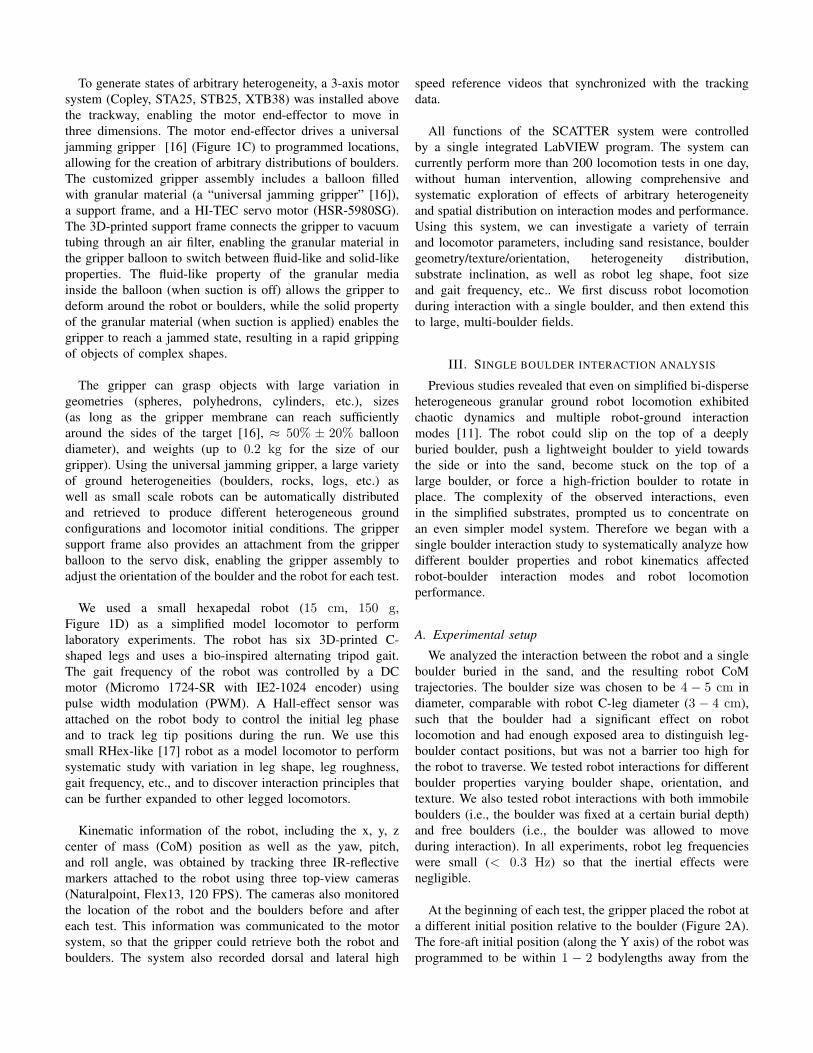
To further validate our hypothesis that fore-aft boulderinclination mainly contributed to scattering angle variation,and further generalize the applicability of our scatteringresults, we tested the robot’s locomotion as it traversedover a cylindrical “log” (5 cm diameter, Fig. 6D, G) fixedat a burial depth of ≈ 3.75cm, with a quarter of the logdiameter protruding from the granular surface. We comparedthe scattering pattern from the cylindrical log with the resultfrom a spherical boulder with the same diameter (Fig. 6A)and same burial depth. We first tested a “half log” (Fig. 6D),where only the legs on the right side of the robot bodyinteract with the log, similar to the situation in the singleboulder experiment. We found that the scattering patternand the scattering angle vs. initial robot fore-aft positionfor the half log (Fig. 6E, F) was qualitatively similar to thescattering pattern of the spherical boulder (Fig. 6B, C). Thiswas consistent with our hypothesis that the scattering angledepended mainly on the fore-aft boulder inclination, and thisindicated another level of superposition in the scattering – thelog can be viewed as a slice of the boulder and the boulderas a superposition of many thin logs of different heightsstacked laterally. We suspect that the difference in magnitudeof the scattering angle depends on the height of the log(i.e., where we “slice” the boulder), and in future work weplan to test different log heights. We note that the scatteringsuperposition approach we propose for the heterogeneousgranular ground is analogous to the granular Resistive ForceTheory (RFT) terradynamics [3] which predicted locomotionperformance on homogeneous granular ground by assumingforces exerted on the robot leg were approximated using alinear superposition of the resistive forces on infinitesimal legelements.
We also tested a “full log” (Fig. 6G) where the legs on bothsides of the robot body can interact with the log. Interestingly,
the robot never travelled straight across the log, instead alltrajectories were separated into two branches (Fig. 6H)with scattering angles greater than 15 ◦ (Fig. 6I). This wassignificantly different from the pattern observed for theboulder or the half log, and was likely due to a “switching”of which side of the legs the dominant scattering modeoccurred. For a robot with initial fore-aft position between19 and 26 cm (≈ 1/2 robot stride length), the interactionbetween the right-side legs and the boulder was causing alarger scattering angle (i.e., was dominating the scattering)as compared to the left-side leg interactions. Thus, the fulllog scattering pattern within this range (Fig. 6I, shadedregion) was qualitatively similar as compared to the half logscattering pattern for right-side leg interactions within thesame range (Fig. 6F, shaded region). For the other 1/2 robotstride length (Fig. 6I, un-shaded region), the left-side legsdominated the scattering, and therefore the full-log scatteringpattern was “inverted” to a left-side half log scattering pattern.
VI. RATIONALIZING SENSITIVE DEPENDENCE OFTRAJECTORY ON INITIAL CONDITIONS
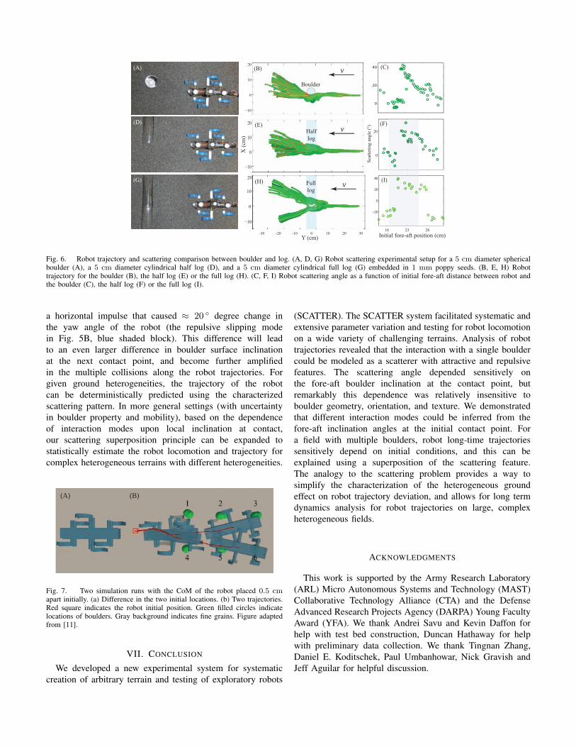
Our scattering superposition principle provides aframework to understand the previously observed chaoticdynamics [19][20] in robot trajectories on a large, multi-boulder field [11]. In our previous results, we noticed thatthe robot’s trajectories were sensitive to initial conditions inboth experiment and our multi-particle DEM simulation [21].Fig. 7 visualizes an example of two simulation runs wherethe Xplorers CoM initial position varied by 0.5 cm in both Xand Y directions (Fig. 7A), while all other initial conditionswere identical (e.g., the robot body axis was initialized to beparallel to the X axis, the initial leg phase was kept the same,and the boulders were distributed to the same locations anddepths). However, after the robot ran across a lattice boulderfield (eight 2.54 cm boulders buried in 3 mm sand), the twotrajectories deviated significantly (Fig. 7B). This sensitivity toinitial conditions is a signature of chaotic dynamics [19, 20].For a larger field with more boulders present, the long termdynamics of the robot will be even more complex.
Using our single boulder scattering pattern and thesuperposition principle, the long term dynamics of robottrajectories on large, heterogeneous ground can be estimated.Based on the scattering superposition principle, each bouldercan be modeled as a scatterer whose scattering direction andmagnitude sensitively dependent on the fore-aft inclination atthe contact point. Since the robot step length is fixed, tworobots which begin 0.5 cm apart in the fore-aft directionwill contact the first boulder (Fig. 7B, boulder 1) with adifference in fore-aft inclination of at least 20 ◦, leading to adifferent scattering angle after the first collision. In the toptrajectory, the leg forced the boulder to yield to the front (theforced sliding mode in Fig. 5B, green shaded block) thusthe robot orientation was not significantly affected. In thebottom trajectory, the leg slipped off the boulder, generating
(A)
0
20
Sca
tter
ing
an
gle
(°)
18 23 28
Initial fore-aft position (cm)
−20
0
20
40
(C)
(D) (F)
(G)
-30 -20 -10 0 10 20 30
−10
0
10
20
−10
0
10
20
Boulder
v
Y (cm)
−10
0
10
20
X (
cm)
Half
log
v
vFull
log
(B)
(E)
(H) (I)
0
20
40
Fig. 6. Robot trajectory and scattering comparison between boulder and log. (A, D, G) Robot scattering experimental setup for a 5 cm diameter sphericalboulder (A), a 5 cm diameter cylindrical half log (D), and a 5 cm diameter cylindrical full log (G) embedded in 1 mm poppy seeds. (B, E, H) Robottrajectory for the boulder (B), the half log (E) or the full log (H). (C, F, I) Robot scattering angle as a function of initial fore-aft distance between robot andthe boulder (C), the half log (F) or the full log (I).
a horizontal impulse that caused ≈ 20 ◦ degree change inthe yaw angle of the robot (the repulsive slipping modein Fig. 5B, blue shaded block). This difference will leadto an even larger difference in boulder surface inclinationat the next contact point, and become further amplifiedin the multiple collisions along the robot trajectories. Forgiven ground heterogeneities, the trajectory of the robotcan be deterministically predicted using the characterizedscattering pattern. In more general settings (with uncertaintyin boulder property and mobility), based on the dependenceof interaction modes upon local inclination at contact,our scattering superposition principle can be expanded tostatistically estimate the robot locomotion and trajectory forcomplex heterogeneous terrains with different heterogeneities.
(A) (B)
Fig. 7. Two simulation runs with the CoM of the robot placed 0.5 cmapart initially. (a) Difference in the two initial locations. (b) Two trajectories.Red square indicates the robot initial position. Green filled circles indicatelocations of boulders. Gray background indicates fine grains. Figure adaptedfrom [11].
VII. CONCLUSION
We developed a new experimental system for systematiccreation of arbitrary terrain and testing of exploratory robots
(SCATTER). The SCATTER system facilitated systematic andextensive parameter variation and testing for robot locomotionon a wide variety of challenging terrains. Analysis of robottrajectories revealed that the interaction with a single bouldercould be modeled as a scatterer with attractive and repulsivefeatures. The scattering angle depended sensitively onthe fore-aft boulder inclination at the contact point, butremarkably this dependence was relatively insensitive toboulder geometry, orientation, and texture. We demonstratedthat different interaction modes could be inferred from thefore-aft inclination angles at the initial contact point. Fora field with multiple boulders, robot long-time trajectoriessensitively depend on initial conditions, and this can beexplained using a superposition of the scattering feature.The analogy to the scattering problem provides a way tosimplify the characterization of the heterogeneous groundeffect on robot trajectory deviation, and allows for long termdynamics analysis for robot trajectories on large, complexheterogeneous fields.
ACKNOWLEDGMENTS
This work is supported by the Army Research Laboratory(ARL) Micro Autonomous Systems and Technology (MAST)Collaborative Technology Alliance (CTA) and the DefenseAdvanced Research Projects Agency (DARPA) Young FacultyAward (YFA). We thank Andrei Savu and Kevin Daffon forhelp with test bed construction, Duncan Hathaway for helpwith preliminary data collection. We thank Tingnan Zhang,Daniel E. Koditschek, Paul Umbanhowar, Nick Gravish andJeff Aguilar for helpful discussion.

REFERENCES
[1] M. G. Bekker. Theory of land locomotion. University ofMichigan, 1956.
[2] J. Y. Wong. Terramechanics and off-road vehicles.Elsevier, 1989. ISBN 0444883010.
[3] C. Li, T. Zhang, and D. I. Goldman. A terradynamicsof legged locomotion on granular media. Science, 339(6126):1408–1412, March 2013. ISSN 1095-9203. doi:10.1126/science.1229163. URL http://www.ncbi.nlm.nih.gov/pubmed/23520106.
[4] G. Meirion-Griffith and M. Spenko. Comprehensivepressure-sinkage model for small-wheeled unmannedground vehicles on dilative, deformable terrain. 2012IEEE International Conference on Robotics and Automa-tion, pages 4052–4057, May 2012. doi: 10.1109/ICRA.2012.6224601. URL http://ieeexplore.ieee.org/lpdocs/epic03/wrapper.htm?arnumber=6224601.
[5] G. Heiken, D. Vaniman, and B. M. French. Lunarsourcebook: A user’s guide to the Moon. CUP Archive,1991.
[6] J.-C. Latombe. Robot Motion Planning, Chapter. 1996.[7] J. Kuffner, S. Kagami, K. Nishiwaki, M. Inaba, and H. In-
oue. Online footstep planning for humanoid robots. Pro-ceedings of IEEE International Conference on Roboticsand Automation (ICRA), 1:932–937, 2003. URL http://ieeexplore.ieee.org/xpls/abs all.jsp?arnumber=1241712.
[8] T. Bhattacharjee and P. Grice. A Robotic System forReaching in Dense Clutter that Integrates Model Pre-dictive Control, Learning, Haptic Mapping, and Plan-ning. Proceedings of the 3rd IEEE/RSJ Interna-tional Conference on Intelligent Robots and Systems(IROS), 2014. URL http://www.hsi.gatech.edu/hrl/pdf/iros2014ws system.pdf.
[9] M. Levihn, K. Nishiwaki, S. Kagami, and M. Stil-man. Autonomous environment manipulation to assisthumanoid locomotion. In Robotics and Automation(ICRA), 2014 IEEE International Conference on, pages4633–4638. IEEE, 2014.
[10] F. Qian and D. I. Goldman. Anticipatory control us-ing substrate manipulation enables trajectory control oflegged locomotion on heterogeneous granular media.In SPIE Defense + Security, pages 94671U–94671U.International Society for Optics and Photonics, 2015.
[11] F. Qian, K. Daffon, T. Zhang, and D. I. Goldman. Anautomated system for systematic testing of locomotionon heterogeneous granular media. in Proceedings of the16th International Conference on Climbing and WalkingRobots (CLAWAR), pages 1–8, 2013.
[12] C. Li, P. B. Umbanhowar, H. Komsuoglu, D. E.Koditschek, and D. I. Goldman. Sensitive dependenceof the motion of a legged robot on granular media.Proceedings of the National Academy of Sciences,106(9):3029–3034, March 2009. ISSN 1091-6490. doi: 10.1073/pnas.0809095106. URL http://www.pnas.org/content/106/9/3029.abstracthttp://
www.pubmedcentral.nih.gov/articlerender.fcgi?artid=2637910&tool=pmcentrez&rendertype=abstract.
[13] F. Qian, T. Zhang, W. Korff, P. B. Umbanhowar, R. J.Full, and D. I. Goldman. Principles of appendagedesign in robots and animals determining terradynamicperformance on flowable ground.
[14] N. Gravish and D. I. Goldman. Effect of volume fractionon granular avalanche dynamics. Physical Review E, 90(3):032202, 2014.
[15] H. Marvi, C. Gong, N. Gravish, H. Astley, M. Travers,R. L. Hatton, J. R. Mendelson, H. Choset, D. L. Hu, andD. I. Goldman. Sidewinding with minimal slip: snake androbot ascent of sandy slopes. Science (New York, N.Y.),346(6206):224–9, October 2014. ISSN 1095-9203. doi:10.1126/science.1255718. URL http://www.ncbi.nlm.nih.gov/pubmed/25301625.
[16] E. Brown, N. Rodenberg, J. Amend, A. Mozeika,E. Steltz, M. R. Zakin, H. Lipson, and H. M. Jaeger.Universal robotic gripper based on the jamming of gran-ular material. Proceedings of the National Academy ofSciences, 107(44):18809–18814, October 2010. ISSN0027-8424. doi: 10.1073/pnas.1003250107. URL http://www.pnas.org/cgi/doi/10.1073/pnas.1003250107.
[17] U. Saranli, M. Buehler, and D. E. Koditschek. Rhex:A simple and highly mobile hexapod robot. The Inter-national Journal of Robotics Research, 20(7):616–631,2001.
[18] M. A. McCord and M. J. Rooks. SPIE handbook ofmicrolithography, micromachining and microfabrication.In SPIE, Bellingham, 2000.
[19] E. N. Lorenz. The essence of chaos. University ofWashington Press, 1995.
[20] S. H. Strogatz. Nonlinear dynamics and chaos: withapplications to physics, biology and chemistry. Perseuspublishing, 2001.
[21] F. Qian, T. Zhang, C. Li, P. Masarati, A. M. Hoover,P. Birkmeyer, A. Pullin, R. S. Fearing, D. I. Goldman,and F. W. Olin. Walking and running on yielding andfluidizing ground. Robotics: Science and Systems (RSS),2012.