the development of the new double acting ships for ice ...€¦ · the development of the double...
TRANSCRIPT

OKHOTSK SEA & SEA ICE, MOMBETSU, JAPAN, 24-28.2.2002
THE DEVELOPMENT OF THE DOUBLE ACTING TANKER FOR ICE OPERATION
Kimmo Juurmaa, Tom Mattsson, Noriyuki Sasaki, Göran Wilkman

THE DEVELOPMENT OF THE DOUBLE ACTING TANKER FOR ICE OPERATION
Kimmo Juurmaa, Tom Mattsson, Noriyuki Sasaki, Göran Wilkman
ABSTRACT
Most of the traditional icebreakers have had good capability to run astern in ice even the vessels are not designed for that. The development during the last 10 years has made it possible that running astern could be considered as the main way of operation in heavy ice conditions. The key to this development is the use of azimuthing podded propulsion, which gives the vessel the benefits of both electric propulsion and excellent maneuverability. These are now combined for the first time. Kvaerner Masa-Yards together with ABB Azipod has developed the concept for more and more demanding projects. Now two 106000 dwt DAT tankers are under construction in Japan by Sumitomo Heavy Industries Inc. However, as the two vessels have not been delivered yet, further development is on its way to study the additional potential of the concept. This paper concentrates on the recent development of the Double acting principle including results from the latest model tests will be discussed. INTRODUCTION
In early 1990’s Kvaerner Masa-Yards started looking at the economics of oil transportation by ships from the Russian Arctic. Figure 1 shows a typical result of these studies. These studies showed that the economics of such transportation is dependent not only on the efficiency to get through the difficult ice conditions but also on the efficiency in open water transit. The fact is that on a direct route from the Arctic to Europe the vessel will spend more than 90 % of her time in open water. The options to solve the this problem are:
�� use of transhipment (like the alternative B in figure 1) �� use of open water hull form and ice breaker assistance �� use of a hull form which is a compromise between open water and ice operation
The direct transportation without transhipment operations has several advantages
including environmental safety and economics. In the comparison in figure 1, the costs of the transhipment terminal are not included and thus the alternative B seems more feasible.
In direct transportation the use of icebreaker assistance has many disadvantages like the availability of such assistance and the costs. Several studies have shown that the most economic alternative is independent direct transportation if only the problem between open water and ice efficiency can be solved.
Based on these studies Kvaerner Masa-Yards started the development of compromise hull forms like those presented figures 2 and 3. Although promising, these forms were always compromises.

Figure 1, Route alternatives
Figure 2, Compromize bow form
Figure 3, Icebreaking bow
At the same time Kvaerner Masa-Yards was conducting development of the propulsion systems for icebreakers. This development resulted in the so-called Azipod propulsion. The testing of this propulsion system in full scale revealed that the vessel could run astern more efficiently than ahead in ice. Combining this finding with the problem of compromised hull form for open water and ice resulted in the development of the Double Acting Tanker (DAT). HISTORY
The idea of using bow propellers on an icebreaking vessel is over 100 years old. The early development utilizing the new technology is described by Juurmaa & al /1/. The older Baltic icebreakers used to have the possibility run 75 % of the engine power either on the bow propellers or on the stern propellers. This means that some overcapacity was built in all of the propeller motors.
The last vessel series built with bow propellers was the URHO-CLASS (Urho, Atle Frey, Sisu and Ymer). In the design of these vessels, the experience from the previous bow propeller vessels as well as model tests was utilized. Special consideration was paid to the shape of the forward bossings. The Urho-class icebreakers were also equipped with two rudders. All these features gave the vessel excellent icebreaking and manoeuvring capability. The optimum power for the bow propellers was found to be 40 %. This considered not only the performance, but also the economics in the required investment.
The effectiveness of bow propellers was tested in several occasions. In the comparison in Figure 4 the third vessel is IB Otso, which is one of the latest stages of vessels having two propellers and two rudders in the stern. The reason to go for this solution was based on the

development of other means of improving the ice performance of the vessels. These included the Air Bubbling System and the use of stainless steel coating in the bow part of the vessel. These other auxiliary devices made it unnecessary to use part of the propulsion power on the bow propellers, which are not efficient in open water.
On an icebreaker with Azipod drive, the situation is different. There also all the propulsion power is installed on propellers in one of end of the vessel. This and is then used either as the bow or the stern depending on the conditions.
The comparison in figure 4 shows the speed in 0.8 m thick level ice with different propulsion arrangements:
� IB Otso, no bow propellers � IB Urho, 40 % of the power at the bow � Azipod icebreaker, 100 % power at the end of the vessel going first
The results show the superiority of the Azipod vessel by 1.5 m/s ( 3kn ) to the Otso-class and 2.5 m/s ( 5 kn ) to the Urho-class. This means that a vessel running astern with the Azipod drive is more efficient icebreaker than any other development. And still the vessel can have a bow which is fully optimised to run in open water.
Figure 4, Effect of propulsion
FIRST APPLICATIONS AND THEIR OPERATIONAL EXPERIENCE The development of the so called Azipod drive was started to take full advantage of the diesel electric power transmission widely used on icebreakers and also to improve the manoeuvring characteristics of icebreakers with bow propellers. The vessels built or under construction so far are listed in table 1. Table 1, Ships with Azipod propulsion Vessel Type Power Year Azipod (MW) units MV Seili Buoy tender 1.3 1990 1 MT Uikku Product tanker 11.8 1993 1 MT Lunni Product tanker 11.8 1994 1 IB Röthelstein Icebreaker 1.1 1995 2 IBSV Arcticaborg Icebreaking supply vessel 3.3 1998 2 IBSV Antarcticaborg Icebreaking supply vessel 3.3 1998 2 IB Bothnica Multi-purpose icebreaker 8.0 1999 2 MT Newbuilding 1 Tanker 16.0 2002 1 MT Newbuilding 2 Tanker 16.0 2002 1
MV Seili Already with first installation onboard buoy tender Seili (figure 5) it was clearly shown that the vessel could perform in astern mode better in heavy ice conditions than her sister ship operating ahead and even utilizing the extra thrust created by the nozzle.

The experience with Seili also showed, that the vessel could easily be steered when operating astern in ice.
The vessel before modification had the ice breaking capability of c. 45 cm of level ice when running forward with a power of 1.6 MW. Because of the rudder arrangement the vessel was not able to brake any ice backwards. After the controllable pitch propeller and the rudder was replaced with an 1.5 MW Azipod unit, the performance was enhanced in every respect:
Figure 5, MV Seili, Azipod
� Ice breaking level ice ahead from 45 cm -> 55 cm, due to better efficiency � Ice breaking level ice astern from 0 cm -> 60 cm, � Crossing old channels no problems
MT Uikku The second vessel to get an Azipod was MT Uikku, a 16000 DWT ice breaking tanker, figure 6, owned by NEMARC (Neste and Kværner Masa-Yards) and operated by ARCTIC SHIPPING SERVICES, Murmansk in the Northern Sea Route. The vessel was originally designed by Wärtsilä (now Kværner Masa-Yards) and built in Germany for Neste Shipping. Today the vessel is operated in the winter primarily in the Baltic and during the summer season in the Northern Sea Route. Occasionally the vessel is also operating in the Arctic during the winter months. This vessel due to the conversion did get before all better manoeuvering behaviour. Also ice breaking performance especially when running astern was improved. The ice resistance in level ice in astern mode was 40 % of that when running ahead, figure 7.
MT Uikku, Ice resistance
0
100
200
300
400
500
0 0.5 1 1.5 2 2.5 3Speed (m/s)
Ice
Res
ista
nce
(kN
) Ahead
Astern
Figure 6, MT Uikku, turning circle Figure 7, MT Uikku, level ice IB Röthelstein The third vessel, IB Röthelstein, a river icebreaker (Danube river) was delivered from Kværner Masa-Yards Helsinki New Shipyard in April 1995, is designed to utilize Azipod propulsion in full. The vessel is designed to break level ice of 70 cm in thickness when running ahead and to break apart/loose 2.5 m thick ice jams. Figure 8 illustrates IB Röthelstein penetrating a ridge (running astern) deeper than the draught of the vessel. The vessel is in operation in figure 9.

Figure 8, IB Röthelstein backing through a ridge. Figure 9, IB Röthelstein in old channel. IBSV Antarcticaborg The experience during the second half of the last decade, both full-scale experience and further development of the concept utilizing model test, has made it more and more obvious that the Double Acting Ship concept has several advantages. The Icebreaking Supply Vessels Arcticaborg and Antarcticaborg operating in the Caspian Sea /2/ have been a great success. Figures 10 and 11 show icebreaking in the Caspian Sea.
Figure 10, IBSV Antarcticaborg Figure 11, IBSV Antarcticaborg penetrating a 7 m thick ridge running astern. Before any big tankers could be designed and built, a lot of development work had to be done. Questions like; stern shape, ice loads on propulsion and hull, behaviour in ballast condition and number of propellers had to be dealt with. Figure 12 shows an a bit different approach, the OB MAX 40 concept, where the bow of the vessel is also designed for icebreaking. The idea was to use this vessel in first year ice area during the winter and to run the vessel bow first during summer time in areas, with lower ice concentration but with a risk to hit multi-year ice blocks. Figure 13 shows one of the early concepts for a single propeller DAT tanker.
Figure 12, OB MAX 40 Figure 13, 90000 DWT DAT
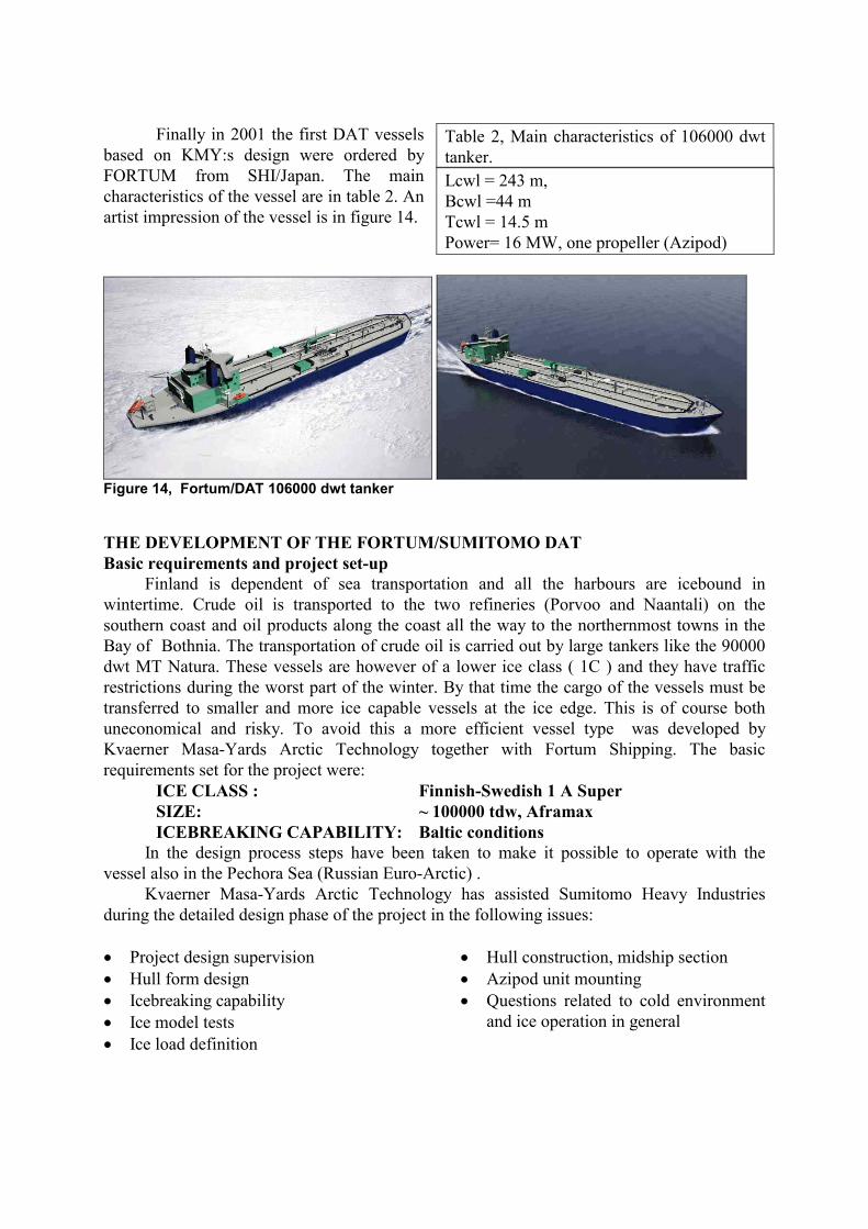
Finally in 2001 the first DAT vessels
based on KMY:s design were ordered by FORTUM from SHI/Japan. The main characteristics of the vessel are in table 2. An artist impression of the vessel is in figure 14.
Table 2, Main characteristics of 106000 dwt tanker. Lcwl = 243 m, Bcwl =44 m Tcwl = 14.5 m Power= 16 MW, one propeller (Azipod)
Figure 14, Fortum/DAT 106000 dwt tanker
THE DEVELOPMENT OF THE FORTUM/SUMITOMO DAT Basic requirements and project set-up
Finland is dependent of sea transportation and all the harbours are icebound in wintertime. Crude oil is transported to the two refineries (Porvoo and Naantali) on the southern coast and oil products along the coast all the way to the northernmost towns in the Bay of Bothnia. The transportation of crude oil is carried out by large tankers like the 90000 dwt MT Natura. These vessels are however of a lower ice class ( 1C ) and they have traffic restrictions during the worst part of the winter. By that time the cargo of the vessels must be transferred to smaller and more ice capable vessels at the ice edge. This is of course both uneconomical and risky. To avoid this a more efficient vessel type was developed by Kvaerner Masa-Yards Arctic Technology together with Fortum Shipping. The basic requirements set for the project were:
ICE CLASS : Finnish-Swedish 1 A Super SIZE: ~ 100000 tdw, Aframax ICEBREAKING CAPABILITY: Baltic conditions
In the design process steps have been taken to make it possible to operate with the vessel also in the Pechora Sea (Russian Euro-Arctic) . Kvaerner Masa-Yards Arctic Technology has assisted Sumitomo Heavy Industries during the detailed design phase of the project in the following issues: �� Project design supervision �� Hull form design �� Icebreaking capability �� Ice model tests �� Ice load definition
�� Hull construction, midship section �� Azipod unit mounting �� Questions related to cold environment
and ice operation in general

Hull form The basic concept of the 1A super ice-class Aframax-size vessel was developed by
Kvaerner Masa-Yards Arctic Technology based on the requirements of Fortum. The further development of the project was done by Sumitomo Heavy Industries with the assistance of Kvaerner Masa-Yards to ensure the success of the construction.
The vessel is designed to follow the Double Acting principal and the hull form is designed accordingly. The vessel will be fitted with a bulbous bow. The bow shape is designed to be capable of operating in light ice conditions related to the Baltic Sea. The stern shape is of ice breaking type, planned to operate independently in the most severe ice conditions of the Baltic Sea. The photographs in Figures15 and 16 show the model. Propulsion
The stern of the vessel is fitted with one Azipod. The designed propeller is fixed bladed with a diameter of 7.6 m. The propeller is of pulling type, which is a typical solution in Double Acting concepts. The estimated bollard pulls at maximum power output (16 MW) is over 2000 kN ahead and nearly 1700 kN astern. The photograph in figure 16 shows the arrangement of the Azipod and propeller.
Figure 15, Bow shape Figure16, Propulsion arrangement Model tests in ice free water Objectives
The objectives of the ice tests are to confirm that the vessel can navigate with specified ship speed at calm sea condition and satisfy IMO interim criteria for maneuverability (A751). Test programme Prior to ice tests, following open water tests were conducted. (1) Resistance and propulsion test (2) Pod open water test Two test facilities were used for the model tests mentioned above. One is SSPA(Sweden). Other is Sumitomo Model Basin(Japan). Results Resistance and propulsion tests The test results were carefully checked and compared with CFD prediction. Figure 17 shows the computed wave patterns for parent ship. Bow shape was optimized by compromising

between open sea performance and ice sea performance. CFD prediction was very useful to estimate the effect of bow shape modification on wave resistance.
Figure 17, Wave pattern obtained CFD method and model test (Resistance test
Pod open water test Open characteristics of pod was investigated by pod open water test. The model test and theoretical study were carried out by Sumitomo using a pod open water instruments in a towing tank and computation code of propeller panel method as shown in figure 18 below.
Figure 18, Pressure distribution (Panel Method) and pod open water test unit Ice model tests Objectives
The objectives of the ice tests performed at MARC were to study the ice going capabilities of the developed Double Acting Tanker (DAT) concept in ice conditions relevant to the Baltic Sea. The tests were planned for generating data on the following issues: The icebreaking capability in level ice, the ice-going performance in unconsolidated and consolidated channels, performance in rubble fields and ridges. Test programme
The test in level ice tests ahead were made in one ice thickness, Hi=0.5 m. The tests astern were performed in two ice thickness; the first one was the same as tested ahead. The second was thicker and was corresponding to 0.8 m thick level ice. Each test mode and ice condition was made at two ship’s drafts; scantling and ballast draft. All of the tests conditions

were performed as self-propulsion tests, with at least two different power outputs. Figures 19 and 20 show the model in level ice.
Figure 19, Model running ahead in level ice Figure 20, Model running astern in level ice
The tests in unconsolidated channels were performed both ahead and astern. This test mode corresponds to a continuously operated channel. Two power outputs were used in each test mode (ahead- astern, and at different tested drafts). The target thickness of the unconsolidated channels was 1m, which is the same as in the propulsion power requirements of the Finnish-Swedish Ice-class rules.
Tests were also performed in a consolidated channel. The test mode corresponds to a channel where the upper layer of the ice blocks were frozen together and formed a 10-20 cm thick consolidated layer in the channel. This happens when there has not been any traffic in the channel for a few days. The target thickness of the frozen channels was also 1 m. The power outputs and drafts were the same as those in the unconsolidated channel tests. Figures 21 and 22 show a typical tested channel and a channel test ahead at scantling draft.
Figure 21, Channel Figure 22, Channel test
Tests in unfrozen rubble field were
performed running astern; at scantling and ballast draught. The unfrozen rubble field corresponds to an ice condition were the rubble is newly formed and not yet consolidated. These tests were made at full power. The thickness of the rubble corresponds to 4 m. Figure 23 shows the model at scantling draft going through a rubble field.
Figure 23, Model in ice rubble
The tests running astern in ridges at full power were performed at both drafts. The tested ridges were relatively small and correspond the conditions in the Baltic Sea. The total thickness of the tested ridges varied from 6 m to 7.8 m. Before the test run the consolidated

ridges were frozen in order to freeze the upper blocks together and to form a solid layer on the top of the ridge. Figures 24 and 25 show the model penetrating a 7 m thick ridge
Figure 24, Model in ridged ice Figure 25, Ridge, underwater Results
Level ice According to the tests, the vessel will reach speed astern of more than 2.5 m/s at both
tested drafts in thin level ice. In 0.8 m thick level ice the predicted speeds will be over 3.5 knots. The predicted ice-breaking capability in continuous mode will be more than 1m thick level ice.
The estimated ice breaking performance ahead at full power out-put (16 MW) is about 0.30 m thick level ice. The result has been extrapolated from tests made with power out puts more than 16 MW. The figure 26 presents a comparison of the ice going capability ahead-astern.
0.0
0.5
1.0
1.5
2.0
2.5
3.0
3.5
4.0
4.5
5.0
0 0.1 0.2 0.3 0.4 0.5 0.6 0.7 0.8 0.9 1
Hi [m]
V s [m/s]ICE BREAKING CAPABILITY
COMPARISON AHEAD- ASTERNIN LEVEL ICE
Ahead
Astern
Figure 26, Icebreaking capability of Double Acting Tanker
Channel The vessel reaches in every tested channel type and mode a speed over 3.4m/s. This is
more than the Finnish-Swedish ice-rules for ice-class 1A requires in unconsolidated channels. The required speed for ice-class 1A Super is 2.5 m/s (5 knots) in consolidated channels. In this way the vessel will fulfill also the 1A Super requirements.
Rubble field In the tested rubble field (about 4 m in efficient thickness) the ship could travel with a
speed over 3 knots in every test mode. The capability to penetrate rubble fields is even better at ballast draft, a speed of about 1.8 m/s was measured in 4.5 m thick rubble.

Ridge The ship will move astern at constant motion in ridges up to a total thickness of about 6-
7 m. At ballast draft the capability ridges is slightly better, the vessel is estimated to move in a ridge of a total thickness of nearly 8 m.
Conclusions from the model tests
The test results show that the vessel fulfils the speed requirements that of the Finnish-Swedish ice rules present for 1A Super vessels for operations in channels. During mild winters it might be even possible to operate in the Gulf of Finland the bulbous bow first. Only extensive rubble fields or large ridges have to be penetrated in the stern first. FURTHER POTENTIAL OF THE DOUBLE ACTING CONCEPT
In the studies made so far and experience gained, it can be noted that a revolution has taken place in ice navigation. The tanker developed by Fortum, Sumitomo and Kvaerner Masa-Yards is unique. Even extensive development work has taken place the story is not over yet. The concept has potential for further development and some steps have been taken already utilizing the possibility to study phenomena in model scale conditions. The questions dealt so far are:
�� shape of the stern �� horizontal location of the propeller �� size of the propeller �� size of the vessel 25000-150000 DWT
Except icebreaking tankers and icebreakers the concept has a huge potential when new
ships are designed for operations in restricted waters (including canals), where traditional configurations have it difficult to cope with the ice. A potential application for multi-directional running of a ship is the Oblique Icebreaker (figure 27), which in addition to break ice with bow and stern also can go sideways and thus make an over 40 m wide channel.
Figure 27, Oblique icebreaker making a wide channel
References: /1/ Juurmaa K., Wilkman G., Bäckström M.,: New Icebreaking Tanker Concept for the Arctic (DAT), POAC 95, Murmansk, Russia. /2/ Arpiainen M., Bäckström M., Juurmaa K., Wilkman G., Veldman K.,: Development of a new icebreaking supply vessel for northern Caspian Sea, POAC 99, Helsinki, Finland