the development of slotted working-section liners for transonic...
TRANSCRIPT

t I I ~ R £ R Y ROYAL AIrCrAfT ~STA~L~PIMI~IqT
MINISTRY OF SUPPLY
R. & M. No. 3085 (zT,7os)
A.R.O. Technical Report
A E R O N A U T I C A L R E S E A R C H C O U N C I L
R E P O R T S A N D M E M O R A N D A
The Development of Slotted Working-Section Liners for Transonic Operation of the
R.A.E. Bedford 3-ft Wind Tunnel
E. P. SUTTON, M.A.
© Crown copyrlg~t z958
LONDON : HER MAJESTY'S STATIONERY OFFICE..
I958 T E N S H I L L I N O S N E T

The Development of Slotted Working-Section Liners for Transonic Operation of the R.A.E.
Bedford 3-ft Wind Tunnel
E. P. SUTTON, M.A.
COMMUNICATED BY THE DIRECToR-GENERAL OF SCIENTIFIC RESEARCH (AIR),
MINISTRY oF SUPPLY
Reports and Memoranda No. 3 0 8 5 *
March, 1955
Summary.--The development of removable slotted liners to extend the range of the Royal Aircraft Establishment 3-It Supersonic Wind Tunnel at Bedford to transonic speeds is described. The liners are mounted within the existing working-section on the two sides, enclosing shallow outer chambers between their slotted surfaces and the original side walls.
At all speeds there was originally a pronounced streamwise pressure gradient, associated with reversed flows in the outer chambers. It was almost eliminated by the addition of perforated screens behind the slots to suppress tnrbulent mixing there.
1. I~troduction.--The 3-ft W i n d Tunne l 1 of the Royal Aircraft Es tab l i shment at Bedford is a pressurised closed-circuit tunne l designed pr imar i ly for supersonic Mach numbers be tween 1.3 and 2.0 , and its working-sect ion is provided wi th in terchangeable shaped nozzle blocks or liners to cover this range. The work repor ted here was unde r t aken to enable the tunne l to be opera ted also at high subsonic and t ransonic Mach numbers up to at least 1.05, using the existing working- section wi th as little modificat ion as possible. Facilit ies would then be available for tests of complete models, of aircraft f rom subsonic speeds up to a Mach number of 2, except for the in terva l be tween 1.05 and 1.3 wi th in which measurements free f rom b o u n d a r y interference by shock-wave reflection could not be expected wi th models of the size (up to 2 ft in length) con- t empla t ed at the time.
The s lot ted working-sect ion me thod ~'8'~ had been developed, pr incipal ly in the U.S.A., as a means of genera t ing stable flows for model tests at Mach numbers cont inuously variable th rough un i ty to about 1.2, almost interference-free apar t f rom shock-wave reflections. A large s lot ted tunne l is described, for example, in Ref. 3. Briefly, the worldng-sect ion is ven ted th rough slots along its length to an outer chamber, or p lenum chamber, the pressure in which is ma in t a ined equal to the stat ic pressure appropr ia te to the free-s t ream Mach n u m b e r required, ei ther b y a p u m p (' auxi l iary suction '), or b y exhaust ing back to the main s t ream in a low-pressure region at the beginning of the diffuser (' diffuser suction '). I t is known tha t model blockage corrections
• at subsonic speeds are less t h a n in a closed tunne l because of the pa r t ly open b o u n d a r y condit ion ; choking at the model can be avoided ; and the s t ream can be accelerated to low supersonic speeds by expansion th rough the slots ups t ream of the model.
* R.A.E. Report Aero. 2536, received 9th August, 1955.

Slotted side liners were devised for the working-section of the 3-it Wind Tunnel, with separate plenum chambers which, for practical reasons given below, were made relatively small compared with those of other transonic tunnels. This proved to be an undesirable limitation, and it is one of the main objects of this report to describe the measures tha t were necessary to obtain a suffi- ciently uniform flow.
The side liners were developed during October and November, 1952, and the final configuration was tested and calibrated at the beginning of 1953. A few of the observations given here have been made since then. The liners are now in use for transonic tests on sting-mounted models, and a turntable is being installed for half-model tests. A completely new transonic working-section is also being built, with slots on all four sides communicating with a single deeper plenum chamber which surrounds it.
2. Adaptatio~ of the Worhi~¢g-Sectio~ by the Use of Detachable Side Limrs.--For supersonic speeds, the working-section of the 3-it Wind Tunnel has interchangeable top liners shaped to form asymmetric nozzles (Fig. 1, inset). The other three sides, which are not readily dismount- able, are flat downstream of the throat. The width of the working-section is 36.0 in. and the height is also 36.0 in. at the model position at the downstream end.
A working-section slotted on two or four sides was preferred for transonic speeds, for the sake of symmetry of the outflow due to model blockage. The pressure ratio available (a maximum of nearly 2.0) was more than adequate for the use of diffuser suction, and there was no need for special at tention to diffuser efficiency. Ease of installation was important, to allow rapid changing over from supersonic to transonic testing and vice versa.
A simple solution was to use a pair of slotted side liners, lowered into the working-section by means of the top liner lifting tackle, and covered with a flat top liner which was already available. To avoid undue reduction of the width of the working-section, the side liners had to be thin, and the plenum-chamber volume within them consequently small. Fig. 1 shows the general arrangement with the side liners installed. They are bolted at their forward ends to the side walls, and at their rear ends to steel blanking discs which replace the schlieren windows.
The side liners themselves are described in detail in Section 3.
A slotted section with parallel sides is formed, 26.8 in. wide by approximately 35 in. high, and 90 in. long*, having two separate plenum chambers of constant depth 4.6 in. To allow for boundary-layer growth, the solid top and bottom walls diverge at an angle of 14 minutes (0. 004 radn) from the horizontal centre plane.
The minimum cross-section area, at the beginning of the parallel-sided slotted section, is 932 sq. in. and the contraction ratio from the settling chamber is 55.
The model position is centred approximately 67 in. fl-om the throat. Two unfaired pairs of shafts span the tunnel at the downstream end of the side liners, passing through the window blanks, carrying either a sting holder from which the model can be supported on a long sting (Figs. 1 and 5b), or a calibrating probe housing (Figs. 1 and 5a) ; for tests through an incidence range, the model is mounted on its side, and an external drive operating on two of the shafts rotates it with the sting about a vertical axis.
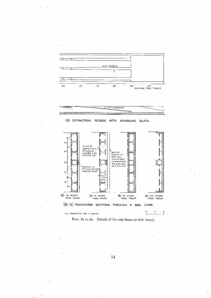
3. Description of the Side Limrs as First Tested.--Cross-sections through the liners in the form in which they were first tested and details of the original configuration of the extraction region are given in Fig. 2; in their overall dimensions, the liners were as shown in Fig. 1. Fig. 5a is a photograph of the working-section with the liners installed.
* For convenience of description, this part of the working-section may be considered as comprising the nozzle region, in which at supersonic speeds the main stream expands through tile slots, and the test section, where a model may be mounted. The extraction region, where air from the plenum chambers is mixed again with the main stream, follows the tes t section.

They were constructed as welded steel frames, largely built-up from standard rolled section members, on which slats and nose surfaces of mahogany were mounted. The surfaces of the slats (like those of the solid top and bottom liners of the working-section), were given a resin-lacquer finish and Worked very smooth and free from short waves.
From their upstream ends, the liners began with nose fairings of approximately quarter- elliptical plan-form, with a semi-axis ratio of 4. The joints between the nose fairings and the side walls to which they were attached were sealed.
Each liner had six slots beginning at the throat (at the end of the nose fairings), of width increasing continuously from zero for the first 54 in., through the nozzle region, and remaining constant at 1-05 in. in the test section. The variation in width through the nozzle region is shown in Fig. 3; it was chosen on the basis of the results of Ref. 3, where a similar (though not identical) slot shape was found to control the expansion so as to give uniform Mach-number distributions in a nearly circular slotted working-section at Mach numbers up to 1-14. The slats were flat throughout the nozzle region and test section. At the model position, where the height of the working-section was 35.3 in., the total width of the six slots in each liner was 6.3 in. The open-area ratio of the slotted sides was 17.9 per cent, and of the whole perimeter 10.1 per cent. The edges of the slats were 0.25 in. thick and had small corner radii (Fig. 3).
The plenum chamber between the slats of each liner and the outer wall had a constant depth of 4.6 in., or approximately 1/6 of the main stream width, measured from the slat surface, in the nozzle region and test section. The structural members on w~hich the slats were supported lay almost entirely along the direction of flow, and there was only one transverse member near to the surface in each plenum chamber, at the end of the model test section (Figs. 1, 2a, 2d, and 5) ; at the same position there was a step of 1 in. in the outer wall, formed by a structural backing plate which extended to the downstream end of the liner (Figs. 1, 2a, 2d, and 2e).
The slats extended into the extraction region (Figs. 2a, 2e and 5a), diverging at an angle of • 5.75 deg from the vertical centre plane after a short transition curve, and ended just ahead of
the first pair of cross shafts of the model support. The .width of the slots increased to 1.50 in. near the beginning of the extraction region. Downstream of the slots, the stream cross-section area was 1.35 times the throat area, and in the plane containing the axis of the first cross shaft 1" 30 times the throat area.
Descriptions of the various modifications which were made in the course of development of the side liners will be found in Section 5 below.
4. Flow Survey Apparatus and Experimental Conditions.~The bottom liner of the working section had a longitudinal row of static-pressure holes, 1 in. to one side of the centre-line, beginning 26 in. downstream of the throat and continuing at 2 or 4-in. intervals to the end of the working- section. During the development of the side liners, longitudinal Mach-number distributions were determined from measurements of static pressure at these holes, together with the settling- chamber pressure. The main features of interest in the curves obtained in this way and presented in Section 5 lie in their shape; their absolute levels are not important, except in so far as com- parisons between two cases should be made at about the same test-section Mach number, and they have not in general been labelled with plenum-chamber pressure or compressor speed. The accuracy of measurement was about 4- 0. 005 in Mach number, limited mainly by the condition of some of the pressure holes and by variations in tunnel speed in the course of a set of readings.
For more detailed streamwise traverses in the test section, a long and very slender tapered probe with a pitot or static head was mounted in the calibrating-probe housing on the cross shafts, ill a plane 1.75 in. above the horizontal centre plane (Figs. 1 and 5a). The pitot head was of 3-ram (0.118 in.) diameter hypodermic tubing, cut off square. The dimensions of the two static heads used are given in Fig. 6, and their aerodynamic characteristics at transonic speeds and
3 (73269) A 2

the corrections which have been applied to their readings are discussed in the Appendix. The accuracy of measurement of static pressure at the probe was equivalent to about 4- 0. 002 in Mach number.
The flow direction was measured at a single point on the centre-line of the worldng-section, 67 in. downstream of the throat, by means of a hemispherical-headed yaw-meter of 0.5-in. diameter 5 mounted on a sting.
There were 9 static-pressure holes at 10-in. intervals along the back of each side liner, at the position shown in Fig. 2b. The mean of the static pressures measured in the two plenum chambers 61 in. from the throat was used, together with the settling-chamber pressure, to determine with an accuracy of ± 0. 002 a reference Mach number MR with which main-stream Mach numbers were compared. Some qualitative observations were made of the flow velocity and direction in the plenum chambers in the plane of symmetry of one of the slots, by the use of a pitot comb and a horizontal brass plate on which light grease was spread.
The flow surveys were made at various constant stagnation pressures between 0.5 and 1.5 Arm and at stagnation temperatures between 5 deg and 30 deg C. The range of Reynolds numbers was from about 0.2 to 0.6 × 10⁶ per in., but no complete investigation of the effects of varying Reynolds number was made. The humidity was always less t han 0.001 lb of water per lb of air, and the frost point was below -- 25 deg C.
5. Development of the Side Liners to Produce a Uniform Flow.--5.1. Performance of the Side Liners in their Original Form.--It was found that the side liners in their original form were effective as a means of enabling the tunnel to be operated at transonic working-section Maeh numbers, but that the flow was not sufficiently uniform for model testing.
In Fig. 7, typical Mach-numher distributions measured at three constant compressor speeds along the line of static-pressure holes in the solid bot tom liner are presented. The two lower curves show a region of approximately constant subsonic or slightly supersonic Mach number, followed, downstream of a point about 45 in. from the beginning of the slots, by a gradual fall in Mach number. At a higher initial Mach number of about 1.1 the distribution had the same general shape, but with a waviness superimposed such as is known to be found 3 when an over- expansion at the beginning of the slots is reflected down tile worldng-section as alternate com- pressions and expansions.
Fig. 8 shows that neither a change in Reynolds number in the range between 0:20 x 106. and 0.37 × 10⁶ per in., nor convergence of the side liners at an angle of 7 minutes (0.002 radn) to the centre plane, had a measurable effect on the Mach-number gradient along the downstream half of the parallel slotted section, except for small changes near the end, downstream of about 80 in. from the throat.
Reduction of the number of slots from 12 to 8 and to 4 by masking with self-adhesive tape was very effective in reducing both the gradient and the waviness (Fig. 9). The change in waviness and the increase observed in the length of working-section required for expansion to a given supersonic speed are attributable to a decrease in the haitial rate of expansion.
This was not regarded as a satisfactory solution, because an open-area ratio of about 10 per cent was considered to be necessary at the model position to minimise wall interference in model tests at subsonic speeds. It was known a that the waviness of the Mach-number distribution at supersonic speeds could be smoothed by changes in the shape of the slots, without reduction in their number or their width in the model test section, but an acceptable method of reducing the 3/Iach-number gradient along the downstream half of the parallel slotted section remained to be found. The gradient was not explicable on a simple geometric basis of changes in the main- stream cross-section area, since the contraction of an isentropic stream, for example, is accom- panied by an increase in Mach number at subsonic speeds but a decrease at supersonic speeds.
4

5.2. Effect of Modifying the Extractio~ Region.--In an investigation of the possibility tha t local upstream flows into the plenum chamber from the extraction region were responsible for the pressure gradient inthe test section, the extraction region was modified. The diverging parts of the slats were removed ; the slotted surfaces then ended 96 in. from the throat, just beyond the transverse structural members at the end of the test section. Wooden blocks as shown in the sketch in Fig. 10 were attached, and their longitudinal position made adjustable. Fig. 10 shows that even when the blocks were adjusted to close the outlets between the transverse structural members and the backs of the plenum chambers completely, the shape of the main-stream Mach-number distributions remained unchanged, except over a distance of less than one stream- width upstream of the modification. The Mach number rose to a peak or increased beyond uni ty near the position of the wooden blocks, owing to local constriction of the total cross-section of the flow.
When the wooden blocks were removed, the slats ended in a plain step. Comparisons made after some of the modifications described below had been carried out showed tha t the Mach- number distribution was the same whether or not the original diverging slat extensions were replaced. In the following, comparative curves showing the effects of other modifications are presented without regard to the presence or absence of the diverging slat extensions.
5.3. Qualitative Observations o f the Flow i~ the Plenum Chambers.~To provide information about the flow in the plenum chambers, observations were made of the movement of light grease on a brass plate mounted behind and along the plane of symmetry of one of the slots (Fig. 2c). The shape of the velocity distributions was also determined at two stations in the same plane from pitot-pressure measurements. The flow pattern observed is sketched in Fig. 11, together with main-stream and plenum-chamber static-pressure distributions.
A zone of turbulent mixing extended into the plenum chamber, bounded at an angle of roughly 5 deg to the slotted surfacefor about 40 in. The boundary then turned more nearly parallel to the slotted surface and the outer wall. For at least 75 in. from the beginning of the slots there was an upstream flow at the outer wall in the plane of observation, supplying air to the turbulent mixing region, with a maximum speed of the order of 1/5 of tile main-stream speed. No observa- tions were made elsewhere in the plenum chamber, and the extent of the upstream flow in the spaces between the slat supports is not known.
Dif~rences in static pressure between the centre plane of the main stream and the plenum chamber at the same streamwise station were everywhere small, as is to be expected in a flow with only small normal velocities and accelerations*. The pressure gradient began, in both the main stream and the plenum chambers, approximately where the mixing zone and the upstream flow first appeared to be constricted by the presence of the outer wall, and was probably due primarily to large shear stresses acting on the shallow upstream flow. Similar flows, with pressure gradients supported in the same way, are found near the point of re-attachment of a separated boundary layer and in the wake behind a rearward-facing step or the blunt base of a projectile ; an analysis of the case where the main stream is supersonic is to be found in Ref. 6.
5.4. Effect of Increasing the D@th of the Plenum Chambers.--One method by which the un- wanted pressure gradient could be eliminated was to increase the depth of tile plenum chambers sufficiently for the turbulent mixing zones to be able to spread without constraint, as in other slotted tunnels. No large increase was possible, however, without an unacceptable reduction of the main-stream width.
By displacement of each side liner as a whole 1.4 in. towards the working-section centre plane and filling the gaps at the ends, the plenum-chamber depth was increased from 4.6 to 6.0 in. This reduced the width of the main stream from 26.8 to 24.0 in., and increased the ratio of plenum-chamber depth to main-stream width from about 1/6 to 1/4.
* There is of course a pressure drop through the slots in the nozzle region at supersonic speeds, but there the normal velocity is higher.
5

The result was to extend the region of nearly uniform subsonic Maeh number by about 15 in., a substantial but inadequate improvement (Fig. 12). The waviness at supersonic speeds was somewhat reduced.
5.5. Effect of Adding Perforated Screens Behind the Slots.--To restrict the spread of turbulent mixing into the plenmn chambers, flat screens of perforated zinc, 0. 045 in. thick with 105 holes per sq in. of 0. 070-in. diameter (open-area ratio 40 per cent) were attached behind the first 48 in. of the slots, 0.5 in. from the surface of the slats, as shown in Fig. 4. At the i r downstream ends, they were notched over a length of 6 in., to reduce the strength of possible disturbances from them at supersonic speeds. The reason for not continuing them over the whole length of the slots was that, as was mentioned above, it was considered desirable to maintain the overall open-area ratio in the test section at about 10 per cent.
Fig. 13 shows MacE-number distributions at subsonic and supersonic speeds with and without the flat screens, with the increased plenum-chamber depth of 6.0 in. The negative MacE-number gradient was slightly reduced at subsonic and very low supersonic speeds, and at the highest speeds it disappeared altogether. I t was in the reduction of waviness at supersonic speeds that the flat screens had most effect, however, by reducing the rate of expansion through the slots in the nozzle region. They were retained for this purpose, disposing of the need for a change in slot shape.
A further set of perforated screens was then added behind 8 of the 12 slots, overlapping the flat screens and extending downstream to the end of the test section. (The other 4 slots were more difficult to modify). They were shaped into channel form (Fig. 4), so that their open area per unit length should exceed the width of the slots screened and the effective open-area ratio of the test section not be much reduced; the exposed open area of each channel was 2-0 sq in. per in. length, while the slot width in the test section was 1.05 in.
The effectiveness of the 8 channel screens is shown in Fig. 14. There was a marked reduction in the gradient in the test section.
The screens were still effective when the plenum-chamber depth was reduced again to 4.6 in. In Fig. 15, MacE-number distributions from Fig. 7 with the liners in their original form are compared with distributions measured at a later date with modified flat and channel screens behind all 12 slots (Section 5.7).
I t is believed that, by restricting the transport of streamwise momentum into the plenum chambers, the screens reduced the mixing behind the slots between the main stream and the air in the plenum chambers. The spee d of any remaining secondary flows in the spaces between the screens and °the outer walls was then relatively low, and there were only small variations in static pressure there. Since the porosity of the screens was high, and the normal velocities through them were low, the pressure drop across them was relatively small and the static pressure was almost constant along the main stream also.
5.6. Effect of an Air Bleed to the Upstream E¢,~ds of the Plenum Chambers.--As the pressure gradient in the plenum chambers appeared to depend on the upstream flow near the walls supplying the mixing regions further upstream, the effect of an independent supply of air was investigated. A slot was left open at the upstream end of each side liner, between the leading edge of the nose fairing and the outer wall, allowing air to flow through to the plenum chambers. The plenum-chamber depth was 6.0 in., and the flat perforated screens but not the channel screens were fitted.
With slots 28 in. long by 0.13 in. wide, the Mach-number distribution was flattened slightly (Fig. 16). With a larger intake of air, through slots 0.90 in. wide, however, the flow deteriorated ; the negative Mach-number gradient began some 20 in. further upstream.
5.7. Final Configuration. New screens of perforated mild steel were installed as a permanent part of the side liners. The flat screens were made longer and their ends cut at an angle Of approximately 8 deg to the stream direction, and the channel screens, now fitted behind all 12
6

slots, were extended further upstream behind the flat screens (Fig. 4). At the same time, the flat part of the slats was extended to 105 in. from the throat, ending in a plain step (Figs. 1 and 5b), and a slot 0.19 in. wide by 35 in. long was left open at the leading edge of the nose fairing of each liner. Fig. 1 shows the working-section assembled with the slotted side liners in their final configuration.
Mach-number distributions with the side liners in this condition, except that the nose slots were sealed, are shown in Fig. 15. Admission of air to the upstream ends of the plenum chambers gave Mach-number distributions that were almost flat to the end of the test section (Fig. 17). It will be seen that a length of about 38 in., or 1.4 times the tunnel width, was needed to expand the stream to a Mach number of 1.14.
The results of a more detai led exploration of the flow in the centre of the working-section, using calibrating probes, are given in the next section.
6. Detailed Flow S~trveys a~$d Calibratio~.--The calibrating probe was used to measure the variation of the Mach number and total head ir~ the test section in a plane 1.75 in. above the horizontal centre plane. Pitot traverses showed the total head to be constant and equal to the settling-chamber pressure to within 4 in. of the side liners, and traverses with the two static heads gave the Mach-number distributions plotted in Figs. 18 and 19. The traverses at Mach numbers of 0.8, 0.9, 0.95, 0.98, 1.04, 1.06 and 1.15 were made with the cone-cylinder static head at a stagnation pressure of 32 in. of mercury; the traverses at 1.00, 1.01 and 1.03 were made with the 3-deg conical static head a t a stagnation pressure of 21 in. of mercury ; and the traverses at 1-08, 1.10 and 1.13 were made with the cone-cylinder static head at a stagnation pressure of 45 in. of mercury. The stagnation temperature was between 15 deg and 30 deg C.
At subsonic speeds, a small streamwise l a c h - n u m b e r gradient remained in the test section, amounting to a fall of about 0. 002 in a length of 16 in. (0.6 of the tunnel width) (Fig. 18). The longitudinal distributions at supersonic speeds were less smooth, but the variation over the same length did not exceed ± 0.004 at Mach numbers up to 1-05. At Mach numbers between 1.05 and 1 .08and again between 1.13 and 1.15, stronger disturbances were present in the test section, causing variations as large, as 4- 0" 008. Variations across the stream in the traverse plane were smaller in general than the streamwise variations (Fig. 19), which suggests that disturbances originating at the top and bottom liners were responsible for much of the non-uniformity. However, no confirmation of this could be found in the spacing of the disturbances, which was more consistent with reflection from the slotted sides.
An at tempt was made to trace the source of one particular disturbance, a compression in which the Mach number fell by about 0. 010 between 65 and 67 in. from the throat at a mean 1Kaeh number of 1.06, without success. It was established, however, that it did not originate from the ends of the flat perforated screens, as had been thought probable ; shortening the flat screens by 5 in. made no significant difference to the distribution along the traverse line in the test section.
The value of the plenum-chamber reference Mach number MR, calculated from the static pressure in the plenum chambers 61 in. from the throat, is given for each of the main-stream Mach-number distributions in Fig. 18. In Fig. 20, the excess over M~ of the average main- stream Mach number along the traverse line between 61 and 77 in. from the throat is plotted against MR; the difference was 0.001 4- 0.002*.
The difference between the reference-static-pressure measurements in the two plenum chambers was within the limits of experimental error. It is important to record that when there is a model at incidence in the test section the pressures in the two sides differ by a small but significant amount, as illustrated in Fig. 21 for the particular case of a large model with a rectangular wing of area 62.5 sq. in. This difference seems likely to be accompanied by an induced upwash ahead of the model, even at supersonic main-stream speeds.
* I t should be noted, however, that this observation depends on the assumption made in the Appendix as to the absolute calibration correction to be applied to pressures measured at the static heads.

The flow direction in the empty working-section, at a point on the centre-line 67 in. from the throat, was found to be inclined at approximately 0.1 deg. to the centre-line, roughly in the horizontal plane, at all speeds.
7. Pressure Ratio.--Measurements of the ratio ,t of the settling-chamber pressure to the static pressure at entry to the compressors, where the air speed was low and the dynamic head did not exceed 0.005 of the settling chamber pressure, are shown in Fig. 22. I t will be recalled tha t the slotted working-section was originally intended to be operated up to a maximum Mach number below 1.1, and that relatively little attention was paid to efficiency. The cross shafts of the model support and the downstream ends of the side-liner structures were not faired, and the diffuser shape close downstream of the working-seckion had been evolved for supersonic operation of the tunnel.
T h e pressure ratio required for the final slotted working-section configuration, including the model-support cross shafts, is given in the top curve of Fig. 22. The maximum Mach number attainable was about 1.15.
In Fig. 28, static-pressure distributions measured along the row of pressure holes in the bottom liner between the test section and the ends of the side liners are plotted, with a scale of Mach number for isentropic flow on the right. They show a rapid expansion and a high velocity peak, followed by a shock, behind the first pair of cross shafts at the higher speeds. At choking, in the sense of insensitivity of the test-section flow to a n y further increase in compressor speed, the main-stream Mach number had reached about 1.6 near the centre plane downstream ; presumably the low-energy stream of air extracted from the plemlm chambers, near the side walls, was still part ly subsonic at lower working-section speeds.
Removal of the cross shafts reduced the pressure ratio at all speeds, and increased the maxi- mum Mach number to about 1.24. Choking occurred when the Mach number near the centre plane reached about 1.5 in the expansion at the end of the slats, at about the same pressure ratio as before. A further increase in maximum test-section Mach number, to over 1.27, was obtained by sealing the slots at the nose fairings of the side liners, reducing the relative volume flow of air to be extracted from the plenum chambers.
8. Discussio~c.--The methods described above may be of use for improving the MacE-number distribution in other transonic wind tunnels. In particular, there may be other cases where a pressure gradient in the working-section for which restriction of the plenum-chamber size is responsible could be reduced by the employment of perforated screens behind the slots. I t would be better, when possible, to ensure in the design of a new slotted working-section that sufficient plenum-chamber depth is provided for screens to be unnecessary. The slotted wall with perforated screens may well be inferior to both the simple slotted wall and the uniformly perforated wall in respect of wall interference in model tests, having neither the probable advantage of the slotted wall at subsonic speeds that the flow through it is more nearly isentropic, nor, at supersonic speeds, the superior shock-cancellation properties, of the perforated wall due to its more uniform porosity. How important this is will depend on the size of model tested*.
I t is difficult to make a general estimate from the results of these tests of the minimum plenum- chamber depth for uniform flow without perforated screens, which will depend on many factors, including the length of the slotted section, the open-area ratio, number and position of the slots, and the shapes of the main-stream and plenum-chamber cross-sections. In the present case, the gradient in the main stream began at a distance of about 10 times the plenum-chamber depth from the beginning of the slots (Fig. 12). To extend the uniform flow in the empty
* The pract ice in the 3-ft Tunnel a t the t ime of wri t ing is to l imit the model length to about 0 .4 of the tes t -sect ion width , so t ha t the reflections of the bow shock wave from the walls will be clear of the ta i l a t a Mach number below 1.15, and to l imi t the model cross-section area to about 0.004 of the s t ream cross-section area. The effects of wall interference on most measurements made on such small models are bel ieved to be small a t Mach numbers up to abou t 1-05, bu t in the range be tween 1.05 and the lowest Mach number a t which the bow shock reflections no longer s t r ike the model, the effects of the reflected shock waves can be large, pa r t i cu la r ly for models wi th tai lplanes.
8

working-section to a distance of 80 in. from the throat, it would have been necessary to increase the plenum-chamber depth to at least 8 in. Thus, very roughly, a slotted working-section with a typical length of about three times the span between the slotted walls would require a plenum- chamber depth not less than about a third of the stream span. In Ref. 4, the flow in a slotted working-section 7.5 in. high "by 3 in. wide, with slots on the 3-in. sides, is described. The two plenum chambers were each 2.5 in. deep, and the length from the beginning of the slots to the beginning of the extraction region was 17 in. With the slotted walls 33.3 per cent open, there was a slight positive pressure gradient along the centre-line at the downstream end of the parallel section, but in the distribution for an open-area ratio of 20 per cent. the gradient was hardly perceptible.
A transonic working-section with perforated walls, or with walls having a large number of very narrow slots, in which the viscous losses are high, will not in general need as deep a plenum chamber as a working-section of the same shape and open-area ratio having Wider slots in which the losses are low.
As a means of reducing the rate of expansion through the slots in the nozzle region at supersonic speeds, the addition of perforated screens will sometimes be much easier than a change of slot shape. A disadvantage is the risk that a finite disturbance may originate where the screens end, especially if they are close to the surface of the slotted wall. Such a disturbance may be expected in cases where there i s a finite pressure drop through the screens at their ends, because the expansion to the test-section speed is incomplete, for example, because of the proximity of a model, or because the screens are inclined to the stream direction. In the present case no disturbance is believed to have been propagated from the ends of the flat perforated screens at Mach numbers up to 1.15 (see Section 6).
In the slotted working-section described in Ref. 3, expansion to Mach numbers up to 1.14 was possible without any init ial over-expansion, with slots of which the rate of increase of width with distance from the throat was greater, in the nozzle region, than in the present case. The section was a regular dodecagon, with 12 slots, uniformly spaced at the corners; the open-area ratio in the test section was 11.1 per cent. Variables which Will influence the initial rate of expansion include t h e velocity distribution across the throat and the wall divergence downstream of the
, throat ; in the working-section of Ref. 3- each slat diverged at an angle of 5 minutes from the centre-line. Experiments reported in Ref. 7 on a square slotted working-section having slots on two sides, four sides, or at the corners (see particularly Fig. 7d of that report) led to the conclusion that the rate of expansion and the subsequent axial variation of Mach number are almost independent of the peripheral location of the slots.
I t was pointed out in Section 5 that a pressure difference was set up between the two plenum chambers when a model was present at incidence in the test section, and that such a difference is likely to be accompanied by an induced upwash ahead of the model. A single plenma chamber completely surrounding the working-section is to be preferred for this reason. Alternatively, separate plenum chambers may be connected by a pressure-equalising duct of sufficiently large cross-section.
9. Conclusio~s.~Slotted working-section liners have been developed for transonic operation of the R.A.E. 3-It Wind Tunnel, which is a pressurised closed-circuit tunnel designed primarily for supersonic operation at Mach numbers between 1.3 and 2.0. They fit inside the existing working-section on two sides, reducing the main stream width from 36.0 to 26.8 in., and have separate plenum chambers, each 4.6 in. deep.
With plain slots, a uniform Mach-number distribution was not Obtained. There was a positive pressure gradient along the downstream half of the slotted section at all speeds, associated with secondary flows set up in the shallow plenum chambers by turbulent mixing at the slots. The gradient developed where the turbulent mixing zones approached the outer wails, and could have been avoided if the plenum chambers had been deeper ; a plenum chamber depth of about 8 or
9

9 in. would have been necessary to delay the beginning of the gradient t o a distance of 3 main- stream spans from the beginning of the slots. It is recommended tha t shallow plenum chambers be avoided in the design of slotted working-sections when possible.
The effects of reducing the number of slots, modifying the extraction region, increasing the plenum-chamber depth, fitting perforated screens behind the slots, and admitting a small independent supply of air to the plenum chambers, were investigated.
Th'e pressure gradient was almost eliminated by the addition of perforated sheet-metal screens behind the slots to restrict the spread of turbulent mixing into the plenum chambers.
The use of perforated screens also prevented over-expansion of the stream near the beginning of the slots at supersonic working-section speeds.
The flow in the working-section with the final configuration of the liners was explored in some detail over a length of 16 in. (0.6 of the stream width). The streamwise variation of Mach number near the centre-line was found to be within ~: 0- 001 at subsonic speeds, q- 0. 004 at Mach numbers between 1.00 and 1.05, and dc 0. 008 at Mach numbers between 1.05 and 1.15.
The maximum working-section Mach number available for tests of sting-mounted models was 1.15, but higher speeds were possible in the absence of the model support.
A static head which had pressure orifices on the surface of a 3-deg cone was used for part of the calibration and found to have advantages over the more conventional type at near-sonic speeds.
No. Author
1 D . E . Morris . . . . . .
2 R . H . Wright and V. O. Ward ..
3 R . H . Wright and V. S. Ritchie . . . .
4 D.W. Holder, R. J. North and A. Chinneck
5 P .G. Hutton . . . . . . . .
6 L. Crocco and L. Lees . . . . . .
7 W . J . Nelson and J. M. Cubbage, Jr. ..
R E F E R E N C E S
T#le, etc.
Calibration of the flow in the working section of the 3 ft × 3 ft tunnel, National Aeronautical Establishment. C.P. 261. September, 1954.
N.A.C.A. transonic wind-tunnel test sections. N.A.C.A. Report No. 1231, 1955 Formerly Research Memo. L8J06, October, 1948.)
Characteristics of a transonic test section with various slot shapes in the Langley 8-ft High-Speed Tunnel. N.A.C.A. Research Memo. L51H10. NACA/TIB/2908. A.R.C. 14,844. October, 1951.
Experiments with slotted and perforated walls in a two-dimen- sionalhigh-speed tunnel. R. & M. 2955. November, 1951.
Static response of a hemispherical-headed yaw-meter at subsonic and transonic 'speeds. R.A.E. Tech. Note Aero. 2525. August, 1957. A.R.C. 19,986.
A mixing theory for the interaction between dissipative flows and nearly isentropic streams. J, Ae. Sci. 19. (10). p. 649. October, 1952.
Effects of slot location and geometry on the flow in a square tunnel at transonic Mach numbers. N.A.C.A. Research Memo L53J09. NACA/TIB/4015. November, 1953.
10

A P P E N D I X
Transonic Characteristics of Two Static Heads a~¢d the Estimation of the True Free-Stream Mach Number
Two static heads (Fig. 6) were used to measure the Mach-number distribution in the neighbour- hood of the proposed model position. No facilities were available for calibrating them at transonic speeds, but the corrections to be applied were estimated on the assumption that there were no sharp variations in the difference between the true-stream static p r e s su reand the plenum- chamber static pressure.
The first s ta t ic head had a conical nose, with apex angle 10 deg, followed by 8 in. of 0" 120-in. diameter hypodermic tubing, and there were 4 equally spaced pressure.holes at a distance of 4 in. (approximately 33 diameters) behind the shoulder. The second consisted of a 3-deg apex-angle cone 2.25 in. long, with 3 equally spaced pressure holes 1.50 in. from the t ip; the diameter of the base of the cone, and of th~ short cylindrical section which followed the base, was 0. 125 in. Each static head was supported on a long tapered probe, the diameter of which increased uniformly from the base diameter of the static head to 1.0 in. in about 44 in. (Fig. 1).
Fig. 24 shows how the Mach nmnber Ms, calculated from the static-head pressure at a point near the centre-line of the stream, varied with the reference Mach number MR calculated from the plenum-chamber static pressure at about the same streamwise position. The accuracy of measurement of both MR and A M ( = M~ -- MR) was about ± 0.002, and the scatter in A M is -4- 0.001.
In the case of the cone-cylinder static head the difference AM was about 0. 004 at reference Mach numbers up to 1.00, with the static head indicating a higher Mach number than the plenum-chamber hole; between 1.00 and 1.02 the difference fell to zero, rose rapidly to 0.010, and fell again. This behaviour is probably due to the passage down the cylindrical part of the static head of a normal shock, which may be variously interpreted as the shock which terminates the local supersonic region following the expansion at the shoulder (if the true stream Math number is less than one), or the bow shock of the supporting probe (if the true stream Mach number is greater than one). The shape of the curve remained the same when the probe was moved longitudinally to other positions in the working-section, but the magnitude of the difference varied because of the small streamwise gradient (Fig. 18). At Math numbers above 1.02, local disturbances propagated through the steam crossed the static holes at Math numbers which depended on the position of the static head in the working-section.
The. rapid variations in AM shown in Fig. 24 render the cone-cylinder static head useless for calibration purposes at Mach numbers between 1-00 and 1.02.
The Mach number indicated by the conical static head varied more smoothly with the reference Mach number, as is to be expected from the position of the pressure holes ahead of the shoulder.
T h e difference A M for the conical static head was constant and equal to + 0" 001 at Mach numbers up to 0.98; it then decreased smoothly to -- 0" 002 at about 1.01.
For free-stream Mach numbers between 1.01 and 1.20, supersonic linear theory predicts a surface Mach number at the cone about 0. 0045 below the stream Mach number. {The flow at the surface of the cone becomes fully supersonic at a Mach number below 1.01). The cone-cylinder static head would be expected to show the true free-stream Mach number before and after the passage of the normal shock over the pressure holes, apart from the effects of any imperfections in the pressure holes themselves.
11

I t was deduced that the mcorrections shown in the following table should be applied to Mach numbers obtained from static-head pressure measurements:
I'r~dicated Mach ~umber A M, to be added to indicated Mach ~umber
Cone-cylinder static head:
0.70 to 0.99 . . . . . . . . . . 0
0.99 to 1.03 . . . . . . . . . . Not used
1 . 0 3 t o l . 2 0 . . . . . . . . . . 0
Conical static head:
0.70 to 0.98 . . . . . . . . . . 0
0.98 to 1.01 . . . . . . . . . . + 0 . 0 0 2
1.01 to 1.20 . . . . . . . . . . + 0 . 0 0 4
and that at Mach numbers between 0.9 and 1.02 the free-stream static pressure near the test- section centre-line, opposite the plenum-chamber reference holes, was 0. 001 4- 0. 002 higher than the reference Math number.
The conical static head was evidently more suitable than the conventional cone-cylinder static head for flow explorations at Mach numbers close to one, and further tests are planned to deter- mine the best position for the orifices and the importance of producing a sharply pointed tip. It should also be more sensitive to weak shocks at supersonic speeds, having its pressure holes closer to the nose where the bounary layer is thinner.
12

h
II II A
ARRANGEMENT FOR SUPERSONIC TESTS~ WITH SHAPED TOP
LINER AND MODEL POSITION BETWEEN
SCHLIEREN WINDOWS
A - -
B I
• ..,.,, ,.,;-
FRONT ELEVATION
REMOVABLE
- - TOP LINER - -
- - A
REMOVABLE
> S I D E LINERS
/11/ I i
2 6 , 8
HORIZONTAL
,-..I
LU ---]1
H
SECTION AA WITH MODEL SUPPORT AND PROBE
DIMENSIONS ARE~ IN INCHES
STATION 12 24 3,6 48 67 105 14g INCHES
THROAT & BEGINNING
- 1 8 O
OF SLOTS
I
I
) ) I
/ / M / / / M / H H / M / / I / M ~ / M M / / I M M / / M , M / M M / M / M / / / / ,
V E R T I C A L SECTION BB WITH M O D E L SUPPORT
FIG. 1. Working-section of 3-ft tunnel with slotted side liners (Final configuration). Inset : Arrangement of working-section for supersonic tests.
I I
SLOT WIDTH~ I-5 I I I
t
' I I I
£ 0 I O O I t O I ~ O ( 3 0 t ~ C I DISTANCE FI~OM TH~OA-~
. . . . . . . . . . . . . . . . . . . . . . . . . . . . . . . . . . . . . . . . . . ~ ~ / / / f l ' / / / / / / / / / / / / / / / / / / / / / / / / / / H
(13) EXTRACTION REGION WITH DIVERGING SLATS.
26 INCHES FROM THROAT
e ) 120 INCHES FROM THROAT
I---4 6
(C~ 61 INCHES
FROM THROAT
J
~d) 93 ,NCHES FROM THROAT
(b)-(~) TRANSVERSE SECTIONS THROUGH A SIDE LINER.
AL.I_ ~IMENSIONS A~E IN INCHF-S . . . . 1 . . . . J
FIGS. 2a to 2e. Details of the side liners as first tested.
14

i.Z5
1.00 WIO"TH O~ SL07 ONCH~S)
0'~
0"50
0'~'5
0 0
/ /
/
~O ZO ~0
/ ~ 1 "65
F
I
, t
.. OlMKNSIOr,4,5 ARE__ IN INI~H~'S
4O 50 6O
FzG. 3. Shape of the sloLs.
I I I '70 80 gO I00 DISTANCE F~0~ THROAT (INCH55)
15

G~
;~ INt-HE6
FLAT SCREENS
FIRST SETS OF SCREENS
? 0 30
FLAT S C R E E N S I I I "
10
~ INCHES
)J
I I I
I
CHANNEL SCREENS INNER SLO~S IN EACH LINE~ ONLY)
FINAL CONFIGURATION
0
50 6O
/ / / / K /- 1
i , . - / /
.40
/
/ / ,/
"/O 8O DISTANC r" ~'ROM TH£OA"r (INCHES)
CHANNEL SCREENS
Fzc. -4 . Positions of the perforated screens.
90
CHANNE~ SCREENS ~ _ _
S C A L E OF LINER CROSS $EC.T~ON . I IN ~NCHES
0 5 IO I , , , , I , , , , I
0,85 ' ~
i 1
,-~s o . 2 o
FLA'r 5CRE~'NS IN THE '~ INNER SI-O-i'S
l- I I
I-
i Z O0
4

,P
FIG. 5a. The liners as first tested, with the slats continued through FIG. 5b. The final configuration with the slats ending abruptly at the the extraction region (with the cross shafts and calibrating probe), end of the parallel section (with the cross shafts and model support).
FIGS. 5a and 5b. The working-section from downstream.
t~

q _ 4 - .
HOLES~ O'QZ~ DIAME'TEN
0.120
~Q) CONE -CYLINDER STATIC HEAD..
i
TIP OIAMETER, 3t d ~0"1")5 ~'5"~ ABOUT 03001 t ~, ,/
~ 5 0 ~ 5 HOLES, O. 014 • ~.5 ~ I" DIAME.'i'ER
(b) 3 ° CONE STATIC HEAD.
FIGS. 6a and 6b. Dimensions of the static heads.
DIMENSIONS ARE IN INCHES.
1-Z
M
1,1
~.0
0 '9
0
Fro. 7.
I MOTOR R.RM.
3 4 0 e----- .---..e----e- -e - - - - - - - - -
~20 e--- ---e----e--
)-----.e
10 ZO 3 0 4 0 .50 60 "70 8 0 9 0 100 DI3TANC..E FROM "rH,EOA-r (INCHES)
Mach-number distributions from bot tom wall pressures--Side,liners in their original form (Plenum-chamber depth = 4.6 in.).
1.2
M
I.C
O'£
O
SIOE LINE£5 PARALLEL R "n" O'ZO x I0'~~ PER IN. : : : : : : : ~ SIDE. LINERS PARALLEl.
o___.< ----o----e--
+ £ "n-o.ZOxlO6PER IN SIOF- LINEI~S C O N Y E ~ E D . . . ~ o AT -]' 70 CENTRE lINE ~
10 2O 3 0 4-0 5Q 6 0 '70 BO £0 OlS'rANCE FROM THROAT (,INC..H~'S ')
100
FIG. 8. Mach-number distributions from bot tom wall pressures--Distributions at two Reynolds uumbers and with the liners parallel and converged (Plenum-chamber
depth = 4.6 in.).
18

1.Z
M
1.1
1"O
0"9
510E LINERS CONYER~ED - - A q" "7' TO CEN"TRE LINE
+ 12 5LOTS A 8 6LO"r,5
'q- 5 L.O'T~
FIG. 9.
t < _ % - .
10 ,','ZO 50 4-0 3 0 eO "70 8 0 90 100 DIST,~,Nr~E F~OIM "I'HROA% (INC_HES)
Mach-number distr ibutions from •bottom walt pressures--Effect of reducing the number of slots (Plenum-chamber depth = 4 .6 in.).
l . Z
M
l . !
1.0
0"9
0 ' 8
o ORIGINAL {3WERGINq 5LAq'S 5LIDIM~ BLOCY,5; b =0.5'
[] SLIDINIG i BLOCKS;b. 0
0 - - - - 4
- - -o - - -¢ - - o - - - o - - ----e-_.e_
~.....49.._..-{B ~
!
/ "-e
-----o.__.e~ ~. o
PLENI.IM CHAMBER DEPTH = 4 .6 INCHES \b \
0 10 20 5 0 4-0 5 0 ,50 '70 SO 90 100 I10 DISTANCE PROM 'TNROAq" (INCHES)
FIG. 10. • ~ a c h - n u m b e r distr ibutions from bot tom wall pressures--Effect of a modification of the extraction region.
19 (73269) C

0.65
0 ' 6 0
0"55 0
X PI...EN~M CHAIMBF.R "e MAiN 8""r~E,~,M
S
J0 20 5 0 4-0 5 0 6 0 7 0
DIS' lANCE FROM -UHNOA"r (iNr"HE$)
M
0 - 8 5 -
O,90 -
0 ' 9 5 -
/ 5° APPROXIMATELY
. . . . .
PLENUM ~H,~MBER DEPTH = 4 .6 INCHES
FIG. 11. Comparison of main-stream and plenum-chamber pressure distributions, and qualitative picture of the flow in the plenum chambers.

M
I.I
I '0
0"9
0
I o PLENUM CNAMISEE
DEPTH =4"~ INCHES MAIN 5"rR, EAM WiDtH = ~6.8 INCNES
x PLENUM ~HAMSER DEPTH :&O INCHES, MAIN STREAM ~I~3"H - Z4'O INCHE.S
F I G . 12 .
I0 ~0 30 40 5o 60 "70 80 90 ~00
DISTANCE. F',~OIM THP~OA"'r (INCNES)
Mach-number distributions from bottom wall pressures--Effect of increasing the plenum-chamber depth.
I.H
M
I.I
1.0
0.£
x NO PE£FOf~ATED SCR.EENS ~ 1 , i
+ PLAT SCi~,EE..NS BEHIND ALL SLOTS - _, ! _ _ . ~ , ~
- FLAG ,SCREENS
"o o Io 'Zo 30
F I G . 13 .
I ~ + . _ _ + _ , f -"- ,+. . . - - -+-
e . ~ ' ' ~ ' -
_ + _ _ ~ o - - - + - - - - - + -
I
40 50 60 70 #0 90 IO0
DISTFANCE F'~OM 'TN~OA"'r (INCNES)
Mach-number distributions from bottom wall pressures--Effect of adding flat screens (Plenum-chamber depth = 6.0 in.).
21

I . Z
I M
I - I
I ' 0
0.9
I
+ FLAT 5CREFN9 QNL~/ e FLAT SCREENS ~:
• CHANNEL SCREENS
rLA~SC~ESNS I (au~ ,~,S~OTS) 0 I0 £0
FIG. 14.
"~ -CHANNEL SCR, EENS
" s-oTs o,.~) 3 0 4 0 5 0 60 -70 8 0 9 0
DISTANCE F~OM -rH~OA'[" ( INCHES)
Mach-number distributions from bottom wall pressures--Effect of adding channel screens. (P;enum-chamber depth = 6.0 in.).
IO0
I 'Z
M
I.I
I'C
0-9
0.~
~
> 0
_ _ e NO PER.FORA'TED
+ FLAG SCIItE~'NS & + ~ " ~ ' - + " ~ - + - - - CHA~INE./ SCI~EEN5 BEHINC ALL SLOVS
PI-ENUM r'HAMf~'~ - ' DEP'fH = 4"6 INCHES
+ - - 4 ~ . - - - - ~ - - + -
A
FI.AT SCREF'NS
I IO ZO 30
FIG. 15. Mach-number
- + ~ + - - + - - + - - + ~
CHANNE~ S ~ E N 5
4 0 5O 6O
+ + +
F-+~+- - - -~ i"
"70 8 0 9 0 I00 ' DISTAN{::E ~'~OM THP~OA'T (INCHES)
distributions from bottom wall pressures--Combined effect of perforated screens.
2 2

1"18
M 1.16
1"14
1.12
I.tO
I . O 8
1"O6
I" 0 4
1"02
I " 0 0
O ' 9 8
O "96
0 " 9 4
O' 92
0 " 9 0
0.88
0 . 8 6
0"84
0 -82
O" 8 0
d£
r
I v
j !
1"145
~ ~ 1"104
.._....__ ^ 1 - 0 8 2
I ~ ~ . ~ _ . ~ ~ - - - ~ - ~ ~ _ e ~ . ~ ~ 1"O63
I I" 0 4 2
I --,-_. ~ ~ - - - , ~ " ~ " ~ " ~ - - ' ~ - - - ~ - . , ~ ~ ~ 1.029
60
I ~ ~ " ~ " ~ . ~ t ~ , ' - ~ . - ' , ~ ~ ~ ~ , , - -~ , - - .~ - .~ , . ~ l ' O O I
. . . .
I
0
3
O I
C
C-
C
0
C 0 i
e I
e MEASURED WITH CONE - CYLINDER STATIC HEAD
WITH 3 ° CONICAL STATIC HEAD & MEASURED
C O
"70
D! STANCE
0
62 64 66 68 7~
f~ v
v
v
C
c ~ - e ~ O 982
O" 952
0 901
I - I g
oc'~ ' " 0 ' ~u . < " ru~ O u a
-r IE U
Z Z
o. W
0 ~ n ' t,~. u. w
'~ 0.
; O" 80 t
74 76 78
F~OM T.ROAT ~NC.ES)
FIG. 18. Long i tud ina l Mach-number d i s t r ibu t ions (FROM PROBE TRAVERSES 1"75 IN. ABOVE THE CENTRE-LINE).
A 2 1 8 3 W t . 5 3 865 6 / 5 8 G p . 9 5 9 F. & C . L t d .

i . ( _
M
I.O
kiP. BLEED 0'9
~.L, ~ ~ " ~ ( 2 L - - . - - - - , - - ~
+NO AI~ 6LEED 7 0 I PLENUM CHAMBERS I
Io A R ADM TGEO THROW~H~"~O'I3"BLOT$
~AIR ADMITTE0 TH~OH~N~8~xO.90~LOT~
'~ . 0
~==- - - - 4 - - - 4 -
O I0 %0 ,.~0 4 0 50 I
= F = , = =
J
60 -7o 8o £o DISTANC.E. FROM -rN&oA'r (,INC.HES)
FIG. 16. Mach-number d is t r ibut ions from b o t t o m wall p ressures - -Ef fec t of an air b leed to the ups t r eam ends of the p lenum chambers (P lenum-chamber dep th = 6 . 0 in. ; first set of flat
per fora ted screens present ; no channel screens).
M
I ' l
I ' 0
0 '9
0"8
PLENLIM CHAMBER - DEPTH =4'6 INC~EB
FI_AT" SCREENS AN0 CHANNEL 3CREENS BEHIND ALL IZ ~LOT$
AiR BLEED TO PLENUM CHAMBERS
7 THROUGH 3~'x0'Z' - SLO'l'8
0 I0
FIG. 17.
~ . .~. .~.a--~ % ~__~_____e~ . .
~ - - - . - ~ - - - - . . o - - ~ ~ • -
~ - - ~ - . ~ - - ~ . . ~..~....-~- - ~ . . . ~ . . ~
zo 3 o 4o ~o eo "7o ao so O~STA~CE FP.OM -rHRoA-T 0NCHES)
Mach-nmnber distributions from bottom wall pressures--Final configuration.
] 0 0
23

tO
M
1.10
1.08
I'0(~
I.O4
1,0C
r
O.g
0"8
0.82
0"66
O~STANC~ ~ o M cE~-r~E P - ~ N ; " (IncHes)
FIG. 19. Lateral Mach-number dis- tributions (from probe traverses along a line 1.75 in. above the horizontal centre plane and 75 in. from
the throat).
÷0'0~_
~ - M R
0
-0 .06
0 0 0 C , ~
0.'7 0"8 0 ' 9 I ' 0 I. I M ~ I'~
FIG. 20. Calibration of plenum-chamber reference- static-pressure holes (M~ = M a c h number from plenum-chamber static pressure 61 in. from the throat ; M~ = Mean Mach number near stream centre-line between 61 and 77 in. from the throat, from probe
traverses).
.+ O.OI
t I -0.011
FIG. 21. Effect of model incidence on the reference static pressure in the two plenum chambers (d~b~ = Stafic pressure difference between plenum chamber on pressure side and plenum chamber on suction side of a model with a rectangular wing of area 62.5 sq in., aspect
ratio 2.5).

1,5 i J o MODEL SWPPOR'I CROSS SHAFTS PRESEN'T C~OSS SHAh'-r5 ASSENT X
¢' CROSS SHAFT6 ASSEN"T, 5LEEE) ! 5LO"rS CLOSED
1"4
1.2
I.I
--N 0.8 0"9 1.0 I.I I,Z
FIG. 22. Tunnel pressure ratio (~.).
j/ 1",4
I-'5
0"3
0,4.
0 .5
>
A
• WITN CROSS .SHAFTS / x W'ITHOu-r C~OSS ,,qHAPT$
. ~ ~ : r
o._ _e___,- - - - .---o----,~ ~
• o-.- ~ - ' t - ' ° ' - ' ~ ' ~ : ' ' ° ' ' r ' ~
7 0 8 0 90
FIC.. 23. Effect
END OF SLA'f'S i I
IOO -I Io
ISENT~PlP.
~ ~..~._~_~_.~.~ / 1.5- N 1.4-
1"2-
I'1-
I'0-
~ ~ o.~-
" ~ ~ o.s~ #x 5HAF~ POSITIONS
12o 13o t.,~o 15o
D~S-rANCE FROM THmOA"F ( INCHES)
of model-support cross shafts on the static-pressure distribution down- stream of the slots.
2 5

+ O'OZ
~ M
,. M M - Mll
0
- O . O Z
r ~
I~ ~ 0 . 4 0 × IO c' PEP-. It.4CN
I I
A g
0 " 9 6 O ' 9 B M,~
( e l ) C O N E - C Y L I N D E R STATIC HEAD.
• + O'OZ
A M : M H - M ~
- O ' O g
o.,:JO O.BZ 0;94 0.96 0.98
I P. --'-. 0,2"7x[0 '~ PE,9. INCH
I I ( b ) 3 ° CONE STATIC . E A D
~ i . o = MR
FIGS. 24a and 24b. Characteristics of the two static heads at Mach numbers near one.
IM,~= MACN NI,JMISE~ DF..D U C... ED FROM PLENUM CI4AMBEI~ 5TA-r I c" PRESSiJ P.E, 61 INCH"8 FROM
TH P.,0A-E
M H- MA~N NUMBEP. DEDUCED FRgM 5TA~I~ H ~ A D P R E ~ U ~ E
26 (73269) Wt . 53]2293 I£'.7 10/58 Hw. PRINTED IN GREAT BRITAIN

R. & M. No .
i i i i i , i iii
Publications of the Aeronautical Research Council
A N N U A L T E C H N I C A L REPORTS OF THE A E R O N A U T I C A L R E S E A R C H C O U N C I L ( B O U N D V O L U M E S )
1939 Vol. I. Aerodynamics General, Performance, Airscrews, Engines. 5os. (52s.). Vol. II. Stability and Control, Flutter and Vibration, Instruments, Structures, Seaplanes, etc.
63s. (65s.)
194o Aero and Hydrodynamics, Aerofoils, Airscrews, Engines, Flutter, Icing, Stability and Control, Structures, and a miscellaneous section. SOS. (52s.)
1941 Aero and Hydrodynamics, Aerofoils, Airscrews, Engines, Flutter, Stability and Control, Structures. 63s. (65s.)
1942 VoL I. Aero and Hydrodynamics, Aerofoils, Airscrews, Engines. 75 s. (77s.) Vol. II. Noise, Parachutes, Stability and Control, Structures, Vibration, Wind Tunnels.
47 s. 6d. (49 s. 6,t.) 1943 Vol. I. Aerodynamics, Aerofoils, Airscrews. Sos. (82s.)
Vol. II. Engines, Flutter, Materials, Parachutes, Performance, Stability and Control, Structures. 9os. (92s. 9d.)
1944 Vol. I. Aero and Hydrodynamics, Aerofoils, Aircraft, Airserews, Controls. 84 s. (86s. 6d.) Vol. II. Flutter and Vibration, Materials, Miscellaneous, Navigation, Parachutes, Performance,
Plates and Panels, Stability, Structures, Test Equipment, Wind Tunnels. 84s. (86s. 6d.)
1945 Vol. I. Aero and Hydrodynamics, Aerofoils. i3on (132s. 9d.) Vol. II. Aircraft, Airscrews, Controls. I3OS. (132s. 9d.) Vol. III . Flutter and Vibration, Instruments, Miscellaneous, Parachutes, Plates and Panels,
Propulsion. I3OS. (I32S. 6d.) Vol. IV. Stability, Structures, Wind Tunnels, Wind Tunnel Technique. 13os. (I 32s. 6d.)
Annual Reports of the Aeronautical Research Council-- 1937 2.f. (2s. 2d.) I938 IS. 6,t. (1.r. 8d.) 1939-48 3s. (3 s. 5 d.)
Index to all Reports and Memoranda published in the Annual Teelmieal Reports, and separately--
April, 195o - R. & M. 26oo 2s. 6d. (2s. Iod.)
Author Index to all Reports and Memoranda of the Aeronautical Research Councib-
19o9--J~nuary, I95" 4 Indexes to the Technical Reports
Council-- December I, I936--June 3 o, 1939 R. & July I, I939--June 3 o, 1945 R. & July 1, i945--June 3 o, 1946 R. & July I, I946--December 31, 1946 R. & January I, I947--June 3 o, 1947 R. &
Published Reports and Memoranda Council--
Between Nos. 225 I-2349 R. & Between Nos. 2351-2449 R. & Between Nos. 2451-2549 R. & Between Nos. 2551-2649 R. &
R. & M. No. 2570 ISS. (I5S. 8d.)
of the Aeronautical Research
M. No. 185o Is. 3d. (rs. 5d.) M. No. 195o is. (rs. 2d.) M. No. 2050 is. (is. 2d.) M. No. 215o IS. 3 d. (rs. 5d.) M. No. 2250 is. 3 d. (IS. 5d.)
of the Aeronautical Research
M. No. z35o is. 9 d. (xs. Iid.) M. No. 245o 2s. (2s. 2d.) M. No. 255o 2s. 6d. (2s. Iod.) M. No. 265o 2s. 6d. (2s. Iod.)
Between Nos. 2651-2749 R. & M. No. 275o 2s. 6d. (2s. rod.)
Prices in ~rackets include postage
H E R M A J E S T Y ' S S T A T I O N E R Y O F F I C E York House, Kingsway, London W.C.2 ; 4.23 Oxford Street, London W.I i r3a Castle Street, Edinburgh 2; 39 King Street, Manchester z ; 2 Edmund Street, Birmingham 3 ; x°9 St. Mary Street, Cardiff; Tower Lane, Bristol I ;
80 Chichester Street, Belfast~ or through any bookseller.
S.O, Code No. 23-3085
R. & M. No. 30,'5_