the development of rotor brakes for wind turbines (52).pdfthis article introduces the design of a...
TRANSCRIPT
International Journal of Applied Engineering Research ISSN 0973-4562 Volume 12, Number 15 (2017) pp. 5094-5100
© Research India Publications. http://www.ripublication.com
5094
The Development of Rotor Brakes for Wind Turbines
JongHun Kang
Assistant Professor, Department of Mechatronics Engineering Jungwon University, Munmu-ro 85, Geosan Gun, Chungbuk,, South Korea.
HyoungWoo Lee*
Assistant Professor, Department of Mechatronics Engineering Jungwon University, Munmu-ro 85, Geosan Gun, Chungbuk,, South Korea.
* Corresponding aurthor
Abstract
This article introduces the design of a rotor brake that imparts
braking force to a rotor disc assembled on the high-speed
coupling of a wind turbine, and includes the verification and
testing of the design. A rotor brake prevents the motion of the
blades in the event of power transmission maintenance, and
stops the wind turbine if there is a failure of the blade pitch
system. Since the rotor brake is a safety-related part, its
structural stability is critical. In addition, the performance of
the brake pad is very important, to deliver the required
braking force. In the present study, a friction test was
performed to choose a brake pad material that ensured stable
braking force, by measuring the friction coefficient of the
brake pads, and a finite element analysis was performed to
evaluate the safety of the individual parts. To verify the
braking force of the designed brake, its performance was
evaluated using a braking force test apparatus.
Keywords: rotor brake, wind turbine components, brake pads,
friction test, finite element analysis
INTRODUCTION
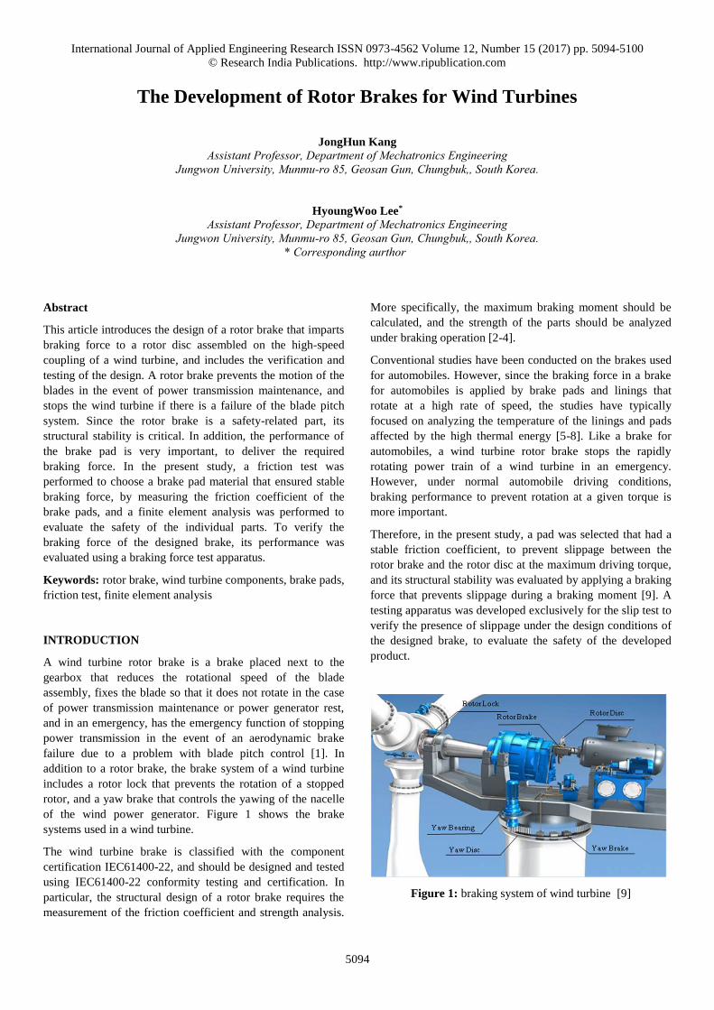
A wind turbine rotor brake is a brake placed next to the
gearbox that reduces the rotational speed of the blade
assembly, fixes the blade so that it does not rotate in the case
of power transmission maintenance or power generator rest,
and in an emergency, has the emergency function of stopping
power transmission in the event of an aerodynamic brake
failure due to a problem with blade pitch control [1]. In
addition to a rotor brake, the brake system of a wind turbine
includes a rotor lock that prevents the rotation of a stopped
rotor, and a yaw brake that controls the yawing of the nacelle
of the wind power generator. Figure 1 shows the brake
systems used in a wind turbine.
The wind turbine brake is classified with the component
certification IEC61400-22, and should be designed and tested
using IEC61400-22 conformity testing and certification. In
particular, the structural design of a rotor brake requires the
measurement of the friction coefficient and strength analysis.
More specifically, the maximum braking moment should be
calculated, and the strength of the parts should be analyzed
under braking operation [2-4].
Conventional studies have been conducted on the brakes used
for automobiles. However, since the braking force in a brake
for automobiles is applied by brake pads and linings that
rotate at a high rate of speed, the studies have typically
focused on analyzing the temperature of the linings and pads
affected by the high thermal energy [5-8]. Like a brake for
automobiles, a wind turbine rotor brake stops the rapidly
rotating power train of a wind turbine in an emergency.
However, under normal automobile driving conditions,
braking performance to prevent rotation at a given torque is
more important.
Therefore, in the present study, a pad was selected that had a
stable friction coefficient, to prevent slippage between the
rotor brake and the rotor disc at the maximum driving torque,
and its structural stability was evaluated by applying a braking
force that prevents slippage during a braking moment [9]. A
testing apparatus was developed exclusively for the slip test to
verify the presence of slippage under the design conditions of
the designed brake, to evaluate the safety of the developed
product.
Figure 1: braking system of wind turbine [9]
International Journal of Applied Engineering Research ISSN 0973-4562 Volume 12, Number 15 (2017) pp. 5094-5100
© Research India Publications. http://www.ripublication.com
5095
ROTOR BRAKE DESIGN
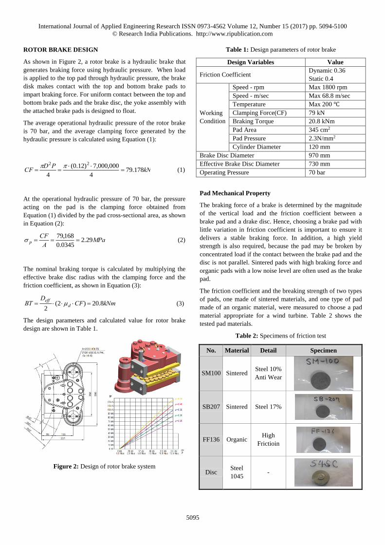
As shown in Figure 2, a rotor brake is a hydraulic brake that
generates braking force using hydraulic pressure. When load
is applied to the top pad through hydraulic pressure, the brake
disk makes contact with the top and bottom brake pads to
impart braking force. For uniform contact between the top and
bottom brake pads and the brake disc, the yoke assembly with
the attached brake pads is designed to float.
The average operational hydraulic pressure of the rotor brake
is 70 bar, and the average clamping force generated by the
hydraulic pressure is calculated using Equation (1):
kNPDCF 178.794
000,000,7)12.0(
4
22
(1)
At the operational hydraulic pressure of 70 bar, the pressure
acting on the pad is the clamping force obtained from
Equation (1) divided by the pad cross-sectional area, as shown
in Equation (2):
MPaA
CFp 29.2
0345.0
168,79 (2)
The nominal braking torque is calculated by multiplying the
effective brake disc radius with the clamping force and the
friction coefficient, as shown in Equation (3):
kNmCFD
BT deff
8.20)2(2
(3)
The design parameters and calculated value for rotor brake
design are shown in Table 1.
Figure 2: Design of rotor brake system
Table 1: Design parameters of rotor brake
Design Variables Value
Friction Coefficient Dynamic 0.36
Static 0.4
Working
Condition
Speed - rpm Max 1800 rpm
Speed - m/sec Max 68.8 m/sec
Temperature Max 200 ℃
Clamping Force(CF) 79 kN
Braking Torque 20.8 kNm
Pad Area 345 cm2
Pad Pressure 2.3N/mm2
Cylinder Diameter 120 mm
Brake Disc Diameter 970 mm
Effective Brake Disc Diameter 730 mm
Operating Pressure 70 bar
Pad Mechanical Property
The braking force of a brake is determined by the magnitude
of the vertical load and the friction coefficient between a
brake pad and a drake disc. Hence, choosing a brake pad with
little variation in friction coefficient is important to ensure it
delivers a stable braking force. In addition, a high yield
strength is also required, because the pad may be broken by
concentrated load if the contact between the brake pad and the
disc is not parallel. Sintered pads with high braking force and
organic pads with a low noise level are often used as the brake
pad.
The friction coefficient and the breaking strength of two types
of pads, one made of sintered materials, and one type of pad
made of an organic material, were measured to choose a pad
material appropriate for a wind turbine. Table 2 shows the
tested pad materials.
Table 2: Specimens of friction test
No. Material Detail Specimen
SM100 Sintered Steel 10%
Anti Wear
SB207 Sintered Steel 17%
FF136 Organic High
Frictioin
Disc Steel
1045 -
International Journal of Applied Engineering Research ISSN 0973-4562 Volume 12, Number 15 (2017) pp. 5094-5100
© Research India Publications. http://www.ripublication.com
5096
Table 3: Test Result of Friction Test and coefficient
No. Result Graph Specimen Fric.
Coef.
SM
100
Min.
0.439
SB
207
Min.
0.275
FF
136
Min.
0.458
The friction coefficient was measured by the pin-on-disc type
measurement method according to ASTM G99-05. The brake
pad friction test to measure the friction coefficient was
performed with a disc of a related material (Steel, S45C))
under a vertical load of 40 N, at a relative speed of 500
mm/sec at a maximum transportation of 3,000 m. Table 3
shows the plots of the friction coefficient test as well as the
friction coefficients obtained from the test.
The design dynamic friction coefficient was 0.4, and the pad
materials that satisfied the condition were SM100 and FF136.
The friction characteristics of both pad materials was
appropriate for a brake pad, because the friction coefficient
values did not vary significantly as the relative movement was
increased.
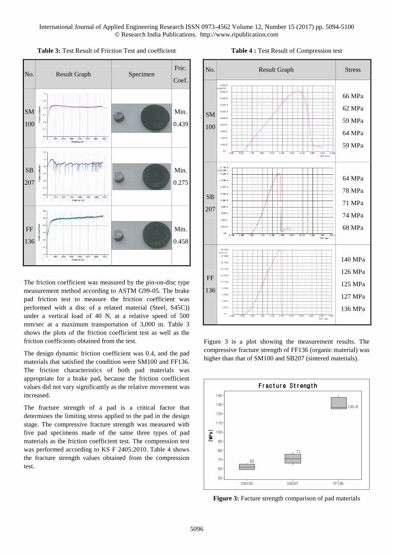
The fracture strength of a pad is a critical factor that
determines the limiting stress applied to the pad in the design
stage. The compressive fracture strength was measured with
five pad specimens made of the same three types of pad
materials as the friction coefficient test. The compression test
was performed according to KS F 2405:2010. Table 4 shows
the fracture strength values obtained from the compression
test.
Table 4 : Test Result of Compression test
No. Result Graph Stress
SM
100
66 MPa
62 MPa
59 MPa
64 MPa
59 MPa
SB
207
64 MPa
78 MPa
71 MPa
74 MPa
68 MPa
FF
136
140 MPa
126 MPa
125 MPa
127 MPa
136 MPa
Figure 3 is a plot showing the measurement results. The
compressive fracture strength of FF136 (organic material) was
higher than that of SM100 and SB207 (sintered materials).
FF136SB207SM100
140
130
120
110
100
90
80
70
60
50
[MPa]
62
71
130.8
Fracture Strength
Figure 3: Facture strength comparison of pad materials
International Journal of Applied Engineering Research ISSN 0973-4562 Volume 12, Number 15 (2017) pp. 5094-5100
© Research India Publications. http://www.ripublication.com
5097
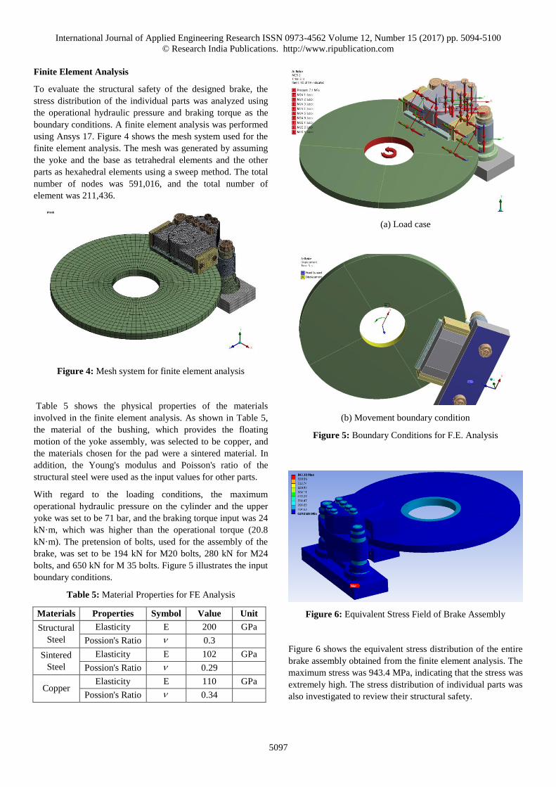
Finite Element Analysis
To evaluate the structural safety of the designed brake, the
stress distribution of the individual parts was analyzed using
the operational hydraulic pressure and braking torque as the
boundary conditions. A finite element analysis was performed
using Ansys 17. Figure 4 shows the mesh system used for the
finite element analysis. The mesh was generated by assuming
the yoke and the base as tetrahedral elements and the other
parts as hexahedral elements using a sweep method. The total
number of nodes was 591,016, and the total number of
element was 211,436.
Figure 4: Mesh system for finite element analysis
Table 5 shows the physical properties of the materials
involved in the finite element analysis. As shown in Table 5,
the material of the bushing, which provides the floating
motion of the yoke assembly, was selected to be copper, and
the materials chosen for the pad were a sintered material. In
addition, the Young's modulus and Poisson's ratio of the
structural steel were used as the input values for other parts.
With regard to the loading conditions, the maximum
operational hydraulic pressure on the cylinder and the upper
yoke was set to be 71 bar, and the braking torque input was 24
kN·m, which was higher than the operational torque (20.8
kN·m). The pretension of bolts, used for the assembly of the
brake, was set to be 194 kN for M20 bolts, 280 kN for M24
bolts, and 650 kN for M 35 bolts. Figure 5 illustrates the input
boundary conditions.
Table 5: Material Properties for FE Analysis
Materials Properties Symbol Value Unit
Structural
Steel
Elasticity E 200 GPa
Possion's Ratio 0.3
Sintered
Steel
Elasticity E 102 GPa
Possion's Ratio 0.29
Copper Elasticity E 110 GPa
Possion's Ratio 0.34
(a) Load case
(b) Movement boundary condition
Figure 5: Boundary Conditions for F.E. Analysis
Figure 6: Equivalent Stress Field of Brake Assembly
Figure 6 shows the equivalent stress distribution of the entire
brake assembly obtained from the finite element analysis. The
maximum stress was 943.4 MPa, indicating that the stress was
extremely high. The stress distribution of individual parts was
also investigated to review their structural safety.
International Journal of Applied Engineering Research ISSN 0973-4562 Volume 12, Number 15 (2017) pp. 5094-5100
© Research India Publications. http://www.ripublication.com
5098
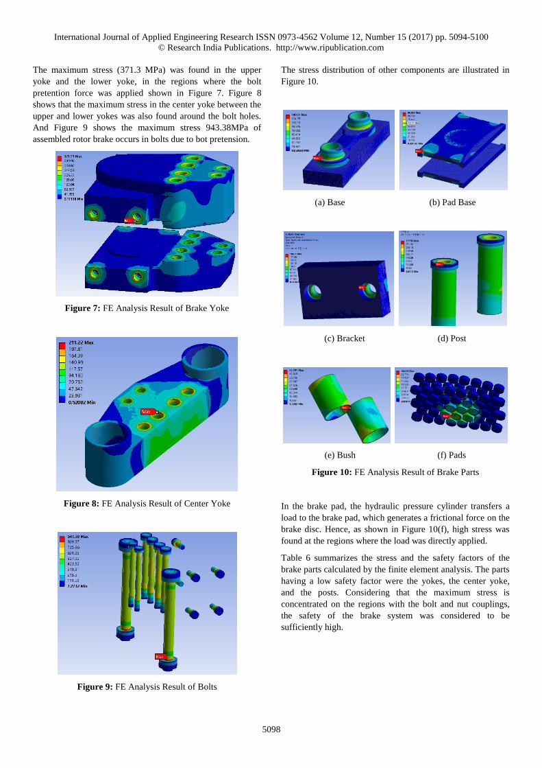
The maximum stress (371.3 MPa) was found in the upper
yoke and the lower yoke, in the regions where the bolt
pretention force was applied shown in Figure 7. Figure 8
shows that the maximum stress in the center yoke between the
upper and lower yokes was also found around the bolt holes.
And Figure 9 shows the maximum stress 943.38MPa of
assembled rotor brake occurs in bolts due to bot pretension.
Figure 7: FE Analysis Result of Brake Yoke
Figure 8: FE Analysis Result of Center Yoke
Figure 9: FE Analysis Result of Bolts
The stress distribution of other components are illustrated in
Figure 10.
(a) Base (b) Pad Base
(c) Bracket (d) Post
(e) Bush (f) Pads
Figure 10: FE Analysis Result of Brake Parts
In the brake pad, the hydraulic pressure cylinder transfers a
load to the brake pad, which generates a frictional force on the
brake disc. Hence, as shown in Figure 10(f), high stress was
found at the regions where the load was directly applied.
Table 6 summarizes the stress and the safety factors of the
brake parts calculated by the finite element analysis. The parts
having a low safety factor were the yokes, the center yoke,
and the posts. Considering that the maximum stress is
concentrated on the regions with the bolt and nut couplings,
the safety of the brake system was considered to be
sufficiently high.
International Journal of Applied Engineering Research ISSN 0973-4562 Volume 12, Number 15 (2017) pp. 5094-5100
© Research India Publications. http://www.ripublication.com
5099
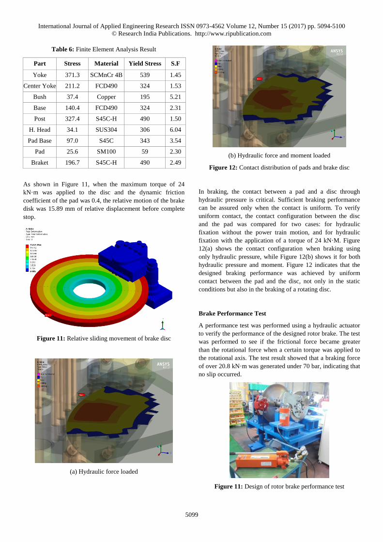
Table 6: Finite Element Analysis Result
Part Stress Material Yield Stress S.F
Yoke 371.3 SCMnCr 4B 539 1.45
Center Yoke 211.2 FCD490 324 1.53
Bush 37.4 Copper 195 5.21
Base 140.4 FCD490 324 2.31
Post 327.4 S45C-H 490 1.50
H. Head 34.1 SUS304 306 6.04
Pad Base 97.0 S45C 343 3.54
Pad 25.6 SM100 59 2.30
Braket 196.7 S45C-H 490 2.49
As shown in Figure 11, when the maximum torque of 24
kN·m was applied to the disc and the dynamic friction
coefficient of the pad was 0.4, the relative motion of the brake
disk was 15.89 mm of relative displacement before complete
stop.
Figure 11: Relative sliding movement of brake disc
(a) Hydraulic force loaded
(b) Hydraulic force and moment loaded
Figure 12: Contact distribution of pads and brake disc
In braking, the contact between a pad and a disc through
hydraulic pressure is critical. Sufficient braking performance
can be assured only when the contact is uniform. To verify
uniform contact, the contact configuration between the disc
and the pad was compared for two cases: for hydraulic
fixation without the power train motion, and for hydraulic
fixation with the application of a torque of 24 kN·M. Figure
12(a) shows the contact configuration when braking using
only hydraulic pressure, while Figure 12(b) shows it for both
hydraulic pressure and moment. Figure 12 indicates that the
designed braking performance was achieved by uniform
contact between the pad and the disc, not only in the static
conditions but also in the braking of a rotating disc.
Brake Performance Test
A performance test was performed using a hydraulic actuator
to verify the performance of the designed rotor brake. The test
was performed to see if the frictional force became greater
than the rotational force when a certain torque was applied to
the rotational axis. The test result showed that a braking force
of over 20.8 kN·m was generated under 70 bar, indicating that
no slip occurred.
Figure 11: Design of rotor brake performance test
International Journal of Applied Engineering Research ISSN 0973-4562 Volume 12, Number 15 (2017) pp. 5094-5100
© Research India Publications. http://www.ripublication.com
5100
CONCLUSION
To develop a rotor brake for wind turbines, a functional brake
design was developed to produce a brake system with high
braking performance. To determine the uniformity of the
braking characteristics, a friction test and a compressive
strength test were performed using three pad materials, to
measure their frictional coefficients and fracture strength. In
addition, a finite element analysis was performed to verify the
structural safety of the designed brake. The analysis
confirmed that the brake had a safe stress distribution under
operational conditions, and the contact between the pad and
the disc was uniform, and did not cause the brake to slip. A
brake prototype was prepared using a SM 100 sintered
material which had a lower fractural strength but a uniform
frictional coefficient. A test apparatus that applied the same
load as the rotor brake during operation was prepared to verify
the performance of the prototype. The test was performed
using the prepared test apparatus, and showed that no slippage
occurred under the load applied in the rotational direction at
maximum pressure, confirming that the rotor brake design
was valid.
ACKNOWLEDGEMENT
This study was conducted as part of the Energy Technology
Development Project of the Korea Institute of Energy
Technology Evaluation and Planning (KETEP).
REFERENCES
[1] Wei Tong, 2010, Wind power generation and wind
turbine design, WIT press, Billerica, USA
[2] Wind turbines - Part 1 : design requirements, 2005,
IEC61400-1
[3] Guidelines for the Certification of Wind turbines, 2010,
Germanischer Lloyd
[4] C. A. P. Travaglia and L.C.R. Lopez, 2014, Friction
Material Temperature Distribution and Thermal and
Mechanical Contact Stress Analysis, Science Research
Engineering, Vol.6, pp.1017~1036
[5] F. Talati and S. Jalalifar, 2009, Analysis of heat
conduction in a disk brake system, Heat Mass Transfer,
Vol.45, pp.1047~1059
[6] S. R. Abhang and D.P. Bhaskar, 2014, Design and
Analysis of Disc Brake, International Journal of
Engineering Trends and Technology, Vol.8, No.4,
pp.165~167
[7] A. Deshpane, 2015, Development of Hydraulic brake
design system application, International Journal of
Research in Science and Technology, Vol.5, No.3,
pp.61~70
[8] A. Belhocine and O.I. Abdullah, 2014, Finite Element
Analysis of Automotive Disc Brake and Pad in
Frictional Model Contact, International Journal of
Design and Manufacturing Technology, Vol.7, No.4,
pp.27~42
[9] J.H Kang and H.W Lee, 2016, The Development of
Wind Turbine Brake by Finite Element Method,
International Journal of Applied Engineering Research,
Vol.11, No. 20, pp. 10294~10298