the development and fabrication of a modular vertical
TRANSCRIPT

East Tennessee State UniversityDigital Commons @ East
Tennessee State University
Electronic Theses and Dissertations Student Works
12-2011
The Development and Fabrication of a ModularVertical Reciprocating Conveyor System for theTransportation of Materials To and From aMezzanine.Matthew Paul CrumEast Tennessee State University
Follow this and additional works at: https://dc.etsu.edu/etd
Part of the Mechanical Engineering Commons
This Thesis - Open Access is brought to you for free and open access by the Student Works at Digital Commons @ East Tennessee State University. Ithas been accepted for inclusion in Electronic Theses and Dissertations by an authorized administrator of Digital Commons @ East Tennessee StateUniversity. For more information, please contact [email protected].
Recommended CitationCrum, Matthew Paul, "The Development and Fabrication of a Modular Vertical Reciprocating Conveyor System for theTransportation of Materials To and From a Mezzanine." (2011). Electronic Theses and Dissertations. Paper 1387. https://dc.etsu.edu/etd/1387

The Development and Fabrication of a Modular Vertical Reciprocating Conveyor System for the
Transportation of Materials To and From a Mezzanine
_____________________
A thesis
presented to
the faculty of the Department of Business and Technology
East Tennessee State University
In partial fulfillment
of the requirements for the degree of
Master of Science in Technology
____________________
by
Matthew Crum
December 2011
_____________________
Dr. J. Paul Sims, Chair
Mr. Bill Hemphill
Mr. Garth Ghearing
Keywords: vertical reciprocating conveyor, conveyor, material lift, lift

2
ABSTRACT
The Development and Fabrication of a Modular Vertical Reciprocating Conveyor System for the
Transportation of Materials To and From a Mezzanine
by
Matthew Crum
The purpose of this developmental project was to design and fabricate a vertical reciprocating
conveyor in order to eliminate the process of manually carrying 27 pound containers of plastic
resin up and down a flight of offset space saver stairs. This project took place and was built for
Phoenix Closures Incorporated. The conveyor was designed and built in house because there are
no commercially available vertical reciprocating conveyors available that meet the necessary
requirements.
The capabilities of the proposed vertical reciprocating conveyor are not limited to the carrying of
the containers but designed to carry vacuum cleaners, tool boxes, and spare parts to the
mezzanine. The vertical reciprocating conveyor is designed for a greater capacity then the 27
pounds the container of plastic resin weighs, but the safety systems are not designed in a way
that would allow the conveyor to lift a greater amount of weight.

3
ACKNOWLEDGEMENTS
I would like to thank the management and engineering department at Phoenix Closures
for allowing me to use this project as my for my own personal benefit and paying me to do so. I
would also like to thank Mr. Bill Hemphill for answering all my ridiculous questions that I seem
to conjure daily.
4
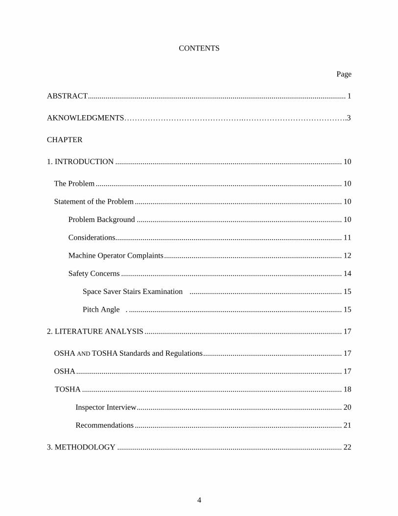
CONTENTS
Page
ABSTRACT .................................................................................................................................... 1
AKNOWLEDGMENTS……………………………………….………………………………….3
CHAPTER
1. INTRODUCTION .................................................................................................................... 10
The Problem .............................................................................................................................. 10
Statement of the Problem .......................................................................................................... 10
Problem Background ......................................................................................................... 10
Considerations.................................................................................................................... 11
Machine Operator Complaints ........................................................................................... 12
Safety Concerns ................................................................................................................. 14
Space Saver Stairs Examination .............................................................................. 15
Pitch Angle . ............................................................................................................. 15
2. LITERATURE ANALYSIS ..................................................................................................... 17
OSHA AND TOSHA Standards and Regulations ....................................................................... 17
OSHA ........................................................................................................................................ 17
TOSHA ..................................................................................................................................... 18
Inspector Interview ......................................................................................................... 20
Recommendations .......................................................................................................... 21
3. METHODOLOGY ................................................................................................................... 22

5
Design Process ........................................................................................................................... 22
Design Criteria .................................................................................................................... 22
Material Selection ...................................................................................................................... 22
Welded Steel Frame vs. Extruded T-slot Aluminum .......................................................... 23
Deflection Test .................................................................................................................... 24
3 Inch by 3 Inch Square Tubing ............................................................................... 24
3 Inch by 3 Inch T-slot Aluminum ........................................................................... 25
Material Selection Results ................................................................................................ 26
Hoist Selection ........................................................................................................................... 27
Electric Cable Winch ..................................................................................................... 27
Electric Chain Hoist ....................................................................................................... 28
Initial Design .............................................................................................................................. 28
Four-Post Conveyor ................................................................................................................... 28
Lifting Structure ........................................................................................................... 28
Material Cart ................................................................................................................ 29
Framework. .................................................................................................................. 29
Guide System ............................................................................................................. 30
Redesign of Conveyor .................................................................................................... 30
New Concepts ............................................................................................................................ 31
Single-Post ..................................................................................................................... 31
Two-Post Conveyor........................................................................................................ 31
Two-Post Conveyor ................................................................................................................... 32
Lifting Structure ............................................................................................................. 32
Material Cart .................................................................................................................. 32

6
Overall Cost ............................................................................................................................... 34
Mezzanine Platform Design ....................................................................................................... 34
Design of Platform ..................................................................................................................... 35
Modification of Hand Rail ......................................................................................................... 35
Safety Gate ................................................................................................................................. 36
Relocating Space Saver Stairs ................................................................................................... 36
4. RESULTS ................................................................................................................................. 37
Fabrication Process .................................................................................................................... 37
Fabrication of Lifting Structure ................................................................................................. 37
Two Main Posts .............................................................................................................. 37
Horizontal Braces ........................................................................................................... 37
Top Horizontal Brace ..................................................................................................... 38
Bottom Horizontal Brace ............................................................................................... 38
Support Braces ............................................................................................................... 38
Fabrication of Material Cart ...................................................................................................... 39
Framework ..................................................................................................................... 39
Door ............................................................................................................................... 39
Guide System ................................................................................................................. 40
Roller Braces ......................................................................................................... 40
Roller Installation . ............................................................................................... 40
Lexan Panels .................................................................................................................. 41
Cart Bottom .................................................................................................................... 41
Hoist Mount Plate........................................................................................................... 42

7
Fabrication of Safety Cage ............................................................................................. 42
Assembly for Testing ................................................................................................................. 43
Process ....................................................................................................................................... 43
Lifting Structure ............................................................................................................... 43
Material Cart .................................................................................................................... 44
Initial Testing ............................................................................................................................. 45
Procedure ................................................................................................................................... 45
Lifting Structure .............................................................................................................. 45
Material Cart ................................................................................................................... 45
Design Modifications ................................................................................................................. 46
Chain Bag................................................................................................................................... 46
Wear Plate .................................................................................................................................. 47
On Site Installation .................................................................................................................... 47
Mezzanine Platform ................................................................................................................... 47
Relocation of Space Saver Stairs ................................................................................... 48
Installation of Platform................................................................................................... 48
Lifting Structure ......................................................................................................................... 48
Installation of Mezzanine Braces ................................................................................... 49
Installation of the Lifting Structure ................................................................................ 49
Material Cart .............................................................................................................................. 50
Safety Cage ................................................................................................................................ 51
On Site Testing .......................................................................................................................... 51
Issues .......................................................................................................................................... 52
Mezzanine Brace Clearance ....................................................................................................... 52

8
Material Cart Bottom . ................................................................................................. 52
Lifting Structure Squareness . ....................................................................................... 52
Material Cart Tracking ................................................................................................. 53
Roller Brace Alignment. ................................................................................................ 53
Electric Chain Hoist Stops ............................................................................................. 54
Bottom Stop.................................................................................................................. . 55
Top Stop. ........................................................................................................................ 55
Hand Guard. ................................................................................................................... 55
Relocation of Electric Chain Hoist................................................................................. 56
Design Issues.. ......................................................................................................... 57
Relocation. ............................................................................................................. 57
Electrical ..................................................................................................................................... 58
Determination of Method of Operation ...................................................................................... 58
Schematic ................................................................................................................................... 58
Control Panel ............................................................................................................................. 58
Control Stations .............................................................................................................. 59
Emergency Switches ...................................................................................................... 59
Door and Gate Switches ................................................................................................. 60
5. SUMMARY .............................................................................................................................. 62
DEFINITION OF TERMS ........................................................................................................... 64
REFERENCES ............................................................................................................................. 66
APPENDICES……………………………………………………………………………...……69
APPENDIX A: Photographs .................................................................................................. 68

9
APPENDIX B: Spreadsheets ................................................................................................. 89
APPENDIX C: AutoCad Drawings ....................................................................................... 92
APPENDIX D: Calculations ................................................................................................ 104
APPENDIX E: Part Descriptions ........................................................................................ 108
VITA ........................................................................................................................................... 116

10
CHAPTER 1
INTRODUCTION
The Problem
Statement of the Problem
The purpose of this developmental research project was to design and build a vertical
reciprocating conveyor to eliminate the need for workers carrying materials up and down stairs.
More specifically the project's purpose was to eliminate machine operators at Phoenix Closures
Incorporated being required to carry 5 gallon containers of plastic resin up and down an Offset
Step Space Saver Stairway. This process is done to access a mezzanine to add colored plastic
resin to a blender to correct an incorrect color blend.
The vertical reciprocating conveyor incorporates three main parts in the design and
fabrication process. The lifting structure, material cart, and safety cage will all be designed and
fabricated in house. This process was documented with analysis, drawings, photographs, and
required parts spreadsheets with prices.
Problem Background
Phoenix Closures is a plastics manufacturer located in Newport, TN. The company
produces plastic caps for the food, beverage, and supplement industries. The company produces
its product though an injection molding process and then a lining machine process that inserts
liners into the caps. All of the caps that Phoenix Closures manufactures are colored based on the
customer's specifications. Phoenix Closures has the capabilities to produce a cap of any color in
the visible spectrum. Located in the molding room or production area of Phoenix Closures’s

11
facility is a mezzanine where 10 blenders mix colored plastic resin with clear plastic resin for
each of the 10 molding machines. These blenders are computer controlled to mix the appropriate
amount of color resin and clear resin to produce the appropriately color cap. In the instance of
certain combinations of color, mold, or cap design the blenders will occasionally not add the
color resin correctly. When this issue occurs, it is the machine operator’s responsibility to correct
the color blend. This is done by the machine operator using a five gallon bucket loaded with
either clear or color resin and carrying it up the mezzanine stairs and adding the appropriate
amount of resin to the blenders. The problem occurring at Phoenix Closures was the requirement
of carrying the five gallon buckets of plastic resin up and down the mezzanine stairs. What made
this process a problem was the type of stairs installed to access the mezzanine. The stairs were
actually a stair and ladder combination officially titled “Offset Step Space Saver Stairway” as
they are listed in McMaster Carr (McMaster-Carr, nd). A top, side, and frontal depiction is
shown in Appendix D (Figure , Figure 60, and Figure 61).
Considerations
The first corrective measure considered by management was replacing the space saver
stairs with a regular staircase. The issue with a regular set of stairs was the required space for the
stairs. Phoenix Closures operates a very lean manufacturing facility and an important aspect of
its lean program is efficient use of floor space. The area under the mezzanine is used for storage
and is also a high fork lift travel area to and from the rear of the molding machines on a regular
basis. The length of the staircase was calculated previously by the engineering department and it
was determined a regular staircase would require too much valuable floor space and would be a
hazard in a high fork lift traffic area. Another reason the standard staircase wasn't an option was
the height of the mezzanine would require the staircase to be custom fabricated. The quote for

12
the custom fabricated stairs was roughly 10,000 dollars, which was not an option for the
company.
The next consideration was the installation of a lift to carry the buckets for the machine
operators eliminating the process of climbing the stairs. Research was conducted to determine if
a lift could be bought and installed next to the mezzanine. The basic criteria for the lift were such
that no commercial supplier was found that fabricated a material lift or vertical reciprocating
conveyor that would meet the initial requirements of the company at a reasonable price.
Designing and fabricating a lift in house by the engineering department was then proposed to the
management. Once the management was on board with proposed plan of building a lifting
device, the research and development phase began.
Machine Operator Complaints
To be able to design the vertical reciprocating conveyor effectively the background and
history of the problem had to be researched so the problem could be better understood. Phoenix
Closures has been at its current location since 2006. During this time period it has increased its
capacity almost yearly with the installation of new equipment. This meant the problem of the
machine operators carrying the buckets up the space saver stairs has increased each year because
of the increased number of machines. According to the engineering department during the first
few years of production the process of carrying the buckets of resin up and down the space saver
stairs was just considered a part of production process at the time.
In the beginning of production only two machines were running; therefore, the actual
process of carrying the buckets was done very few times during the production process. As
production increased the number of machines increased, and the number of times machine

13
operators were required to carry the bucket of resin up the stairs increased dramatically as well.
What also increased was the number of complaints about this process by the machine operators.
The machine operators’ complaints were different depending on whether the operator
was male or female. The operators were randomly interviewed with the guarantee of anonymity
about its concerns and opinions on the process of carrying the buckets of resin up the space saver
stairs. Below are a few selected answers that give the overall scope of the machine operators
concerns.
“Well, my big issue with the ladder (the offset step stair way) is that I'm a big guy and I
have hard enough time going up and down them on my own, let alone carryin' that bucket. It's
not the weight of it, it's just getting you and the bucket down the steps at the same time”
“In all honesty, I'm surprised someone hasn't fallen off them carrying that thing., and ya
know it's only gonna get worse with the new side of the plant “
“I dropped it once so that should tell you how hard it is for me, If I can I'll have a level 5
carry it up for me” “I can carry it around on the floor fine but I can't carry it up those stairs.”
The first two comments were made by a Level 5 Machine Operator which is the highest
level of machine operator. Level 5 machine operators have the most experience and the most
training of any operators employed at Phoenix Closures. The last comment made was by a
female machine operator. This particular female machine operator was small in stature making
carrying the bucket up the space saver stairs even more difficult.

14
The complaints that have been made throughout the company's five years at the current
location posed the question of why the management decided recently to fix the issue. The second
complaint made by the Level 5 operator caused the most concern for the management. During
the spring of 2011 Phoenix Closures began an expansion project that would eventually double its
manufacturing space and capacity. Included in this expansion was the addition of a new
mezzanine and two new sets of the space saver stairs that were installed in the same way as the
previously installed set. Once these new sets of space saver stairs were installed, the complaints
increased and the management was forced to take action on the matter.
Safety Concerns
Phoenix Closures takes the safety of its employees very seriously and because of its
dedication to safety the conveyor was being considered as a solution to the problem. The
problem, which has been stated previously, was the carrying of 5 gallon buckets of plastic resin
up and down the space saver stairs. The company has received safety complaints about this
process, but substantial evidence of a safety issue was needed before a costly project, such as the
conveyor, could progress any further.
The question that was raised was how dangerous is the process of carrying the buckets
up the stairs and does it warrant a major correction? The question of how dangerous is the
process is a valid question. It is human nature to find reasons not to do a process, job, or task that
someone does not wish to do because one does not like doing it. Research began on the safety of
the issue of carrying the buckets up and down the stairs, how dangerous it is, and if it indeed
does warrant major changes.
The machine operator's safety concerns were studied and the issue that was raised by
Machine Operator 1 of “getting you and the bucket down the steps at the same time” was the first

15
to be physically examined. The machine operator who stated this concern was asked to
demonstrate his or her technique for carrying the bucket and how it related to his or her concerns.
Once the operator began climbing the stairs with the bucket in hand, it was visibly apparent why
the operators were complaining about the process. To carry the bucket up the stairs the operator
was forced to carry the bucket in front of his or her body. It was observed that the angle of the
stairs left little room between the operator's body and the steps to actually carry the bucket. The
operator also stated during this examination that if the bucket was loaded with resin, it took both
hands to carry the bucket. This meant the operator would not be able to use the handrails while
ascending the stairs. Descending the stairs was done in much the same manner only in reverse.
Space Saver Stairs Examination. The next aspect to be examined was the stairs
themselves. The width of the stairs was found to be 23 inches between the hand rails. To put this
width into perspective the average interior door width is 32 inches which means the space saver
stairs are 9 inches narrower than a standard interior doorway. The diameter of a standard five
gallon bucket is 11.875 inches at its widest point. What this measurement proves is that it is
impossible to carry the bucket off to one's side, as the majority of people carry buckets. This is
because there is not enough space between the handrails for the bucket and the person carrying
it. The person carrying the bucket is required to remove hands from the hand rail and carry the
bucket in front of the body as the person goes up and down the stairs.
Pitch Angle. The pitch angle of the stairs accent to the mezzanine was calculated to be
64.9 degrees (Figure ). The angle for the space saver stairs is over twice the average pitch angle
of between 20-38 degrees for a normal comfortable set of stairs which makes them more
dangerous to climb then a standard set of stairs (The Staircase, n.d.). This level of danger is
exasperated by the fact the machine operators are required to ascend and descend the stairs

16
carrying a 27 pound bucket without using the handrails. Another factor that plays a definite role
in the steep angle of the stairs and process by which the machine operators are carrying the
buckets is the amount of space between its body and the stairs to actually carry the bucket when
ascending the stairs. The Space Saver Stairs Angles Drawing (Figure 52) shows that at a level of
3 feet, where most people would carry a bucket in front of its body there is only 1.41 feet
between the person's body and the stairs. As stated previously, the bucket has a diameter of
almost 12 inches. This only leaves roughly half an inch between the person, the bucket, and the
stairs. Half of an inch would be sufficient clearance to carry a bucket on a level surface, but up
and down a 64.9 degree flight of stairs that have offset foot pad half of an inch is nowhere near
enough clearance for this to be a safe process.

17
CHAPTER 2
LITERATURE ANALYSIS
OSHA and TOSHA Standards and Regulations
OSHA
The Occupational Safety and Health Administration (OSHA) conducts random
inspections of workplaces all over the United States. OSHA has various rules and regulations in
the form of standards and it requires companies to meet and follow these standards. Phoenix
Closures takes safety very seriously and makes every attempt to create the safest working
environment possible under the rules set by OSHA. After the initial design of the conveyor was
formulated, the determination was there had to be OSHA regulations pertaining to a device such
as the conveyor. Classifying the device became a major hurdle as OSHA does not recognize the
title of vertical reciprocating conveyor in any of its standards; therefore, a similar device's
standards would have to be used. At first it was thought that an elevators standard would meet
the needs of the project. Below is the OSHA standard for the definition of an elevator.
“1917.116 (a) "Elevator" means a permanent hoisting and lowering mechanism with a car
or, platform moving vertically in guides and serving two or more floors of a structure. The term
excludes such devices as conveyors, tiering or piling machines, material hoists, skip or furnace
hoists, wharf ramps, lift bridges, car lifts and dumpers (OSHA, 1996).”
Standard 1917.116 (a) gives the definition of what OSHA considers an elevator. In the
second sentence of the standard also states what it does not consider an elevator. What this
means is the conveyor is not an elevator but still could be considered a material hoist, material
lift, or a conveyor. A vertical reciprocating conveyor is basically the same device as a material
hoist or lift; therefore, the standard for material hoists and lifts will be used.

18
Now that the device has been classified under material hoists and lifts, further standards
could be studied and compared against the initial design. This has been done and the initial
design can be modified to fit the safety standards set forth by OSHA. Below are the OSHA
standards pertaining to material hoists and lifts.
“1926.552(a)(1) The employer shall comply with the manufacturer's specifications and
limitations applicable to the operation of all hoists and elevators. Where manufacturer's
specifications are not available, the limitations assigned to the equipment shall be based on the
determinations of a professional engineer competent in the field (OSHA, 1987). “
“1926.552(a)(2) Rated load capacities, recommended operating speeds, and special
hazard warnings or instructions shall be posted n cars and platforms (OSHA, 1987)”.
“1926.552(b)(1)(i) Operating rules shall be established and posted at the operator's
station of the hoist. Such rules shall include signal system and allowable line speed for various
loads. Rules and notices shall be posted on the car frame or cross head in a conspicuous location,
including the statement "No Riders Allowed." (OSHA, 1987)
“1926.552(b)(1)(ii) No person shall be allowed to ride on material hoists except for the
purposes of inspection and maintenance (OSHA, 1987). “
“1926.552(b)(5)(i) When a hoist tower is enclosed, it shall be enclosed on all sides for its
entire height with a screen enclosure of 1/2-inch mesh, No. 18 U.S. gauge wire or equivalent,
except for landing access (OSHA, 1987).”
TOSHA
In addition to OSHA many states have an occupational safety organization. In Tennessee
that organization is known as the Tennessee Occupational Safety and Health Administration
(TOSHA). TOSHA, just like OSHA, has a set of standards and will inspect businesses for

19
compliance with and violations of its safety standards. The differences between OSHA and
TOSHA are that TOSHA is only in the state of Tennessee, and TOSHA has a different set of
standards then OSHA. TOSHA is also different from OSHA in that it has an Elevator Division
that not only sets the standards for the state but also has its own elevator inspectors. The
standards from the Elevator Division were researched similar to the OSHA.
The TOSHA Elevator Division not only inspects elevators but also dumbwaiters,
escalators, and other lifts. As defined by OSHA the conveyor is not an elevator, but it could be
considered a dumbwaiter or under the gray area of “other lifts.” The issue with the conveyor
being considered any of these is apparent in section General Requirements under paragraph 5
and 6 pertaining to Permits and Registration shown below (TOSHA, 2007).
“0800-3-4-.02 (5) Construction Permits. “
“(a) A construction permit shall be obtained from the Department before erecting or constructing
new elevators, dumbwaiters, escalators, and other lifts, moving such apparatus from one
hoistway to another, or before making alterations to existing equipment. The owner, or his
authorized agent, shall submit an application for such permit accompanied by plans and
specifications in duplicate, in such form as the Department may prescribe. Where such plans
and specifications indicate compliance with this Chapter the Commissioner shall issue a
construction permit.”
“ (6) Registration of Elevators, Dumbwaiters, Escalators and Other Lifts.”
“(a) Within sixty days after the date of adoption of this Chapter, the owner or lessee of every
existing elevator, dumbwaiter, escalator, and other lift shall register with the Department of
Labor and Workforce Development each such elevator, dumbwaiter, escalator, or other lift
owned and operated by such owner, giving type, contract load, and speed, name of
manufacturer, its location and the purpose for which it is used and such other information as the

20
Department may require. Such registration shall be made on a form to be furnished by the
Department of Labor and Workforce Development on request.”
“(b) Elevators, dumbwaiters, escalators, and other lifts whose erection is begun subsequent to the
date of adoption, but prior to the effective date of this Chapter, shall be registered with the
Department within not more than 7 (7) days after they are completed and placed in service”
(TOSHA, 2007).
Once this was discovered the Safety Coordinator at Phoenix Closures was notified to the
possibility of the conveyor requiring permits and inspections. The main issue was if the conveyor
would fall under the heading of other lifts as there is no clear definition of TOSHA's meaning of
other lifts.
Inspector Interview
It was decided that further information was needed and contact was made to the TOSHA
Elevator Division for clarification of the standards. A phone interview was conducted with Mr.
Ron Fidler, the chief elevator inspector for the State of Tennessee. According to Mr. Fidler, the
classification of a lifting device is determined on the size of the material cart. Also, the fact the
conveyor is completely enclosed has a large bearing by determining the classification. Mr. Fidler
stated that “because your cart size and the structure being enclosed, your device is considered by
the state as a dumbwaiter.” (Fidler, personal communication, 2011) He went on further to state
“The weight rating of your power source, in this case it is my understanding an electric chain
hoist, has no bearing on the decision of the device's classification as it is based on size. This is
how all elevators and enclosed lifting devices are classified. You would have to build your lift
according to ASME or ANSI standards for it to pass inspection.” (Fidler, personal
communication, 2011) Further inquiry was made to Mr. Fidler of the process of inspection and

21
permits, “If the lift passed its first inspection this would cost $400 for the initial permit, and then
the lift would have to be inspected twice a year to keep its permit at a cost of $150 per
inspection.” (Fidler, personal communication, 2011)
Recommendations
Once this information was gathered, it was expressed to Mr. Fidler that Phoenix Closures
was not in the elevator business and that the company was just attempting to build a device to
make a job easier. Mr. Fidler was then questioned on how to build a lifting device that would not
require inspection and permits, “well, based on your problem as you've described it, I would
suggest opening the device up making it more like a hoist with a guide.” “Your problem now is
that someone could stick their head in the bottom and the cart could fall.” “You need to make the
lift to where someone could see it falling” (Fidler, personal communication , 2011)
Once the phone conversation with Mr. Fidler had concluded, the information was passed
to Phoenix Closures management. It was decided the best route for the project would be to
redesign the conveyor so that it would not have to be inspected. This also meant that the lift
would not have to be built to ASME or ANSI standards. The sticking point for the ASME and
ANSI standards is once again the cost upwards of $300 to obtain the standard. The conveyor will
still be built to comply with applicable OSHA and TOSHA standards.

22
CHAPTER 3
METHODOLOGY
Design Process
Design Criteria
The initial design process for the vertical reciprocating conveyor was conducted with the
intent of what design will work for Phoenix Closures’s needs and wants.
It must be able to lift a five gallon bucket of plastic resin weighing 27 pounds to the
mezzanine
The material cart must be large enough to carry spare parts such as electric motors,
pumps, small tool boxes, and vacuum cleaners.
Must be compact where the conveyor will not waste floor space
Can be disassembled if needed
Free Standing or with the smallest amount of bracing from the mezzanine
Powered by 110 volt electricity
Make the machine safe and avoid issues with OSHA and TOSHA
Material Selection
As stated previously, the engineering department at Phoenix Closures was in charge of
approving all the design aspects of the conveyor. This also included the materials used in
fabrication of the conveyor. The desire of the engineering department was to have something that
could either be assembled easily in house or have an outside contractor fabricate the structure
based on a design that was generated in house. The two materials the engineering department
suggested the conveyor be fabricated from were steel and T-slot aluminum.

23
Welded Steel Frame vs. Extruded T-slot Aluminum
A welded steel frame work was the first option considered. The steel frame work was
first considered because of the raw materials are generally more cost effective and readily
available from local suppliers. If a steel framework was to be used, the possibility of having
outside contractors fabricate the lifting structure of the conveyor as a time saving measure was
considered. The initial proposal for a steel frame work was for the lifting structure to be
fabricated from thee inch by 3 inch box tubing with quarter inch thick walls. The material cart
would be fabricated from either one inch by one inch box tubing or angle iron. All of the joints
of the frame will be welded together to assemble the two frames. At this point in the design
process, the size and shape of the steel were only general ideas.
The second option was an extruded T-slot aluminum framing system. With this framing
system the entire conveyor would be fabricated in house by the designer. As with the steel frame
work, two sizes of the T-slot aluminum would be used during the fabrication of the lifting
structure and material cart. The current advantage to the T-slot aluminum over the welded steel
frame is Phoenix Closures has an ample supply of the necessary sizes of T-slot aluminum
available in house.
T-slot aluminum is available in various sizes or profiles that are designated into different
series. The two series that were considered in the building of the conveyor were the 10 and 15
series. The 10 series of T-slot aluminum is a smallest series of profiles (Figure 63). To assemble
the pieces into a frame work the 10 series channels or grooves are made to accept 1/4-20 screws
and t-nuts (Figure 68). The 15 series (Figure 62) is a larger profile of T-slot aluminum uses 5/16-
18 screws and t-nuts for its assembly method. The lifting structure of the conveyor would be
built from 3 inch by 3 inch 15 series T-slot aluminum. The material cart would be fabricated

24
from one inch by one inch 10 series T-slot aluminum and have a type of steel plate that will be
used for the bottom of the cart (80/20 Inc., nd).
Deflection Test
To scientifically prove which of the two materials was stronger, three different deflection
tests were taken for each material. A calculation was made with the overall length of the
conveyor of 20 feet and with the part fixed at two points. This test gave an overall comparison of
the two materials. The next calculation was the length of the part as if it were braced by the
mezzanine. This changes the calculated length to 13 feet 7 inches and fixed at both ends. The last
calculation that was made was for the remaining portion of the conveyor from the previous
calculation. This calculated length was 6 feet 5 inches and the part was fixed at one point
3 Inch by 3 Inch Square Tubing. In order to calculate the deflection for the 3 inch by 3
inch square tubing, standard steel calculations were used. The formula for the deflection of a
beam fixed at both ends and the formula for a steel cantilevered beam was used (American
Institute of Steel, nd). Although the deflection calculations for square tubing are the same as a
steel beam, calculating the moment of inertia is different. To calculate the moment of inertia for
square tubing first the moment was calculated for the outside dimensions of the square tubing
that was 3 inches by 3 inches. The next step was to calculate the moment of inertia for the inner
dimensions of the square tubing that was 2.5 inches by 2.5 inches. The final step for calculating
the moment of inertia is to subtract the inner dimension's moment of inertia from the outer
dimension's moment of inertia. Once this has been done the moment of inertia for the 3 inch by 3
inch tubing has been calculate (American Institute of Steel, nd).
The modulus of elasticity was the last piece of information needed to complete the
deflection calculation. The modulus of elasticity is a constant based upon the type of steel and

25
the thickness of the walls of the steel tubing; therefore, no calculations were needed for this. The
modulus of elasticity was found to be 29 million pounds per square inch (American Institute of
Steel, nd). The three calculations were completed with the information that had been gathered
(Figure 56, Figure 57, Figure 58).
3 Inch by 3 Inch T-slot Aluminum. Calculating the deflection of T-slot aluminum was
done differently from calculating the deflection for the square tubing. This was because the
inside profile of the T-slot aluminum extrusion was full of gussets and channels making it
stronger than square aluminum tubing. Therefore, to calculate the deflection of the T-slot
aluminum a computer program was provided by 80-20 Inc., which produced the T-slot
aluminum.
Basic parameters were required for the program to calculate the deflection for the T-slot
aluminum. These parameters are listed below with the required data listed below each separate
parameter.
The profile part number that was being used
3030S
The weight of the load that will be placed on the part
27 pounds
The length of the part that would be used
120 inches, 152.4 inches, and 87.6 inches
With this information the program can calculate the deflection for the T-slot aluminum.
The program produced results in tables that were then placed into Word documents (Figure 53,
Figure 54, Figure 55).

26
Material Selection Results
After the calculations have been completed, a measurable determination was made on
which material was more appropriate and would be used to fabricate the conveyor. As stated
previously, the first calculation that was conducted was using the overall length of the conveyor
with both ends fixed (Figure 56).The results of this calculation show the deflection in the square
tubing as .0222 inches while the deflection of the T-slot aluminum was calculated to be .0609
inches (Figure 53 and Figure 56). The next calculations showed how the material would react
when attached to the floor and mezzanine. Both of the ends were still fixed as in the first
calculations, but this time the distance from the floor to the mezzanine braces was used for the
part length. The results of this set of calculations showed the steel was still slightly stronger than
the T-slot aluminum as the steel's deflection was .0057inches (Figure 57) and the T-slot
aluminum's was .0156 inches (Figure 54).
The final calculation was for the remaining section of the conveyor that would be above
the mezzanine. This calculation was different from the previous calculations as the formula for a
single fixed part was used. Once again the steel was slightly stronger then the T-slot aluminum
as the steel's deflection was .0691 inches (Figure 58) and the aluminum's was .1865 inches
(Figure 55).
What these calculations proved was the steel square tubing was not much stronger the T-
slot aluminum. Further comparisons were made concerning the ease of fabrication of the steel
tubing compared to the T-slot aluminum and the cost of fabrication from each material. These
factors were presented to the engineering department for its final decision on selecting the
material for the conveyor. It was determined cooperatively by the designer and the engineering
department to use the T-slot aluminum. The main reasons for using the T-slot aluminum over the
steel tubing were that if any modifications were needed to any part of the conveyor, they would

27
be much easier using the T-slot aluminum. The next reason was the company had a large supply
of the T-slot aluminum on hand which made the price of the project much less than using steel
tubing.
Hoist Selection
The material selection process was concluded by selecting the type of device to power the
conveyor. The conveyor was not going to be designed to lift a great amount of weight; therefore,
the lifting device would not have to be excessively strong. The engineering department was
asked for what requirements they had for the hoist selection which is listed below.
Powered by 110 volt electricity
Lift no less than 100 pounds
Fifteen foot travel distance
The reasons the engineering department had these particular requirements were mainly
for simplicity. One hundred ten volt electricity meant the conveyor could simply be plugged into
an existing wall outlet. The engineering department required the hoist to lift more than 100
pounds because if the conveyor project was a failure the hoist can be used elsewhere in the plant.
The travel distance was selected because it will eliminate the amount of slack in the chain when
the material cart is on the floor.
Electric Cable Winch
The first device that was considered was an electric winch that would use a steel braided
cable to lift the material cart. Research was done on various aspects of electric winches such as
payload limit, length of cable, and prices. A suitable unit was discovered and presented to the
engineering department for approval. The engineering department did not however approve the
cable winch as they believed the steel braided cable introduced a few problems. The main issue

28
was that steel braided cable has the tendency to wear and could possibly break over the life of the
conveyor. This was an overwhelming reason not to use an electric winch on the conveyor.
Electric Chain Hoist
The second option for the lifting device was and electric chain hoist. Similar aspects that
were researched previously for the electric winch were also researched while looking for a
suitable electric chain hoist. An electric chain hoist capable of lifting 500 pounds, had a travel
distance of 15 feet, and was powered by 110 volt electricity was selected and presented to the
engineering department. The engineering department approved the hoist selection and it was then
purchased.
Initial Design
The initial design of the vertical reciprocating conveyor was the first complete concept
that was presented to the engineering department. The initial design was to show the engineering
department the plan for conveyor and how it would be built and if the theory of the conveyor was
valid.
Four-Post Conveyor
Lifting Structure
The initial design of the lifting structure of the vertical reciprocating conveyor used four
posts that completely enclosed the material cart. The four posts would be built from the T-slot
aluminum framing system. The posts would use the 15 series 3 inch by 3 inch profile. The four
vertical posts had to be 20 feet tall in order for the material cart to reach the mezzanine floor.
Two sides of the four-sided lifting structure would be horizontally connected using the same 15
series T-slot aluminum as the four main posts. They would be connected using the eight hole 15
series angle brackets. The other two sides of the structure would be horizontally braced by a one

29
and a half inch by 3 inch 15 series T-slot aluminum. The reason for using the one and a half inch
instead of the 3 inch profile was the clearance of the material cart rollers described later. These
braces would be connected by using the four hole angle brackets (Figure 65). All of the braces at
the top of the lifting structure would be fabricated from the 3 inch by 3 inch 15 series to add
strength for mounting the electric chain hoist. The electric chain hoist would be mounted to one
piece of 3 inch by 3 inch 15 series that would be attached across the top of the frame. The hoist
would then be hung from an eye bolt that is mounted through the 3 inch by 3 inch piece. The
frame is to be attached to the floor using the eight hole angle brackets and standard concrete
anchors. The lifting structure will stand 20 feet tall and have a square footprint of 30 inches
(Figure 41, Figure 42).
Material Cart
Framework. The framework of the material cart would be made from one inch by one
inch 10 series T-slot aluminum. The frame work would be assembled by using the four hole 10
series angle brackets and ¼-20 t-nuts and button head screws (Figure 65, Figure 68). The cart
will be four feet tall and have a two foot square footprint. This will allow everything the
company wishes to load onto the lift to be loaded easily. A swing out door with magnetic latches
will be fabricated onto the loading side of the cart. The latches will hold the door shut in-case of
the load shifting during operation. The bottom of the cart will be fabricated from a piece of
diamond plate steel. This will ensure that even if the conveyor is overloaded the bottom of the
cart will not fall through. To contain any spills of resin that could occur in the material cart, .375
thick Lexan sheets will be fabricated and installed into the sides and top of the cart. The Lexan
will be slid into the groove of the T-slot aluminum locking it in place. The rollers mentioned
previously will be mounted to all four corners of the cart. The electric chain hoist will be

30
attached to the back top brace of the cart frame work with a 4 inch long eye bolt with a 1.5 inch
opening installed into the top brace of the lifting structure.
Guide System. The guide system for the material cart was the most complicated aspect
of the initial design process. Multiple acceptable forms of guiding the cart up the lifting structure
exist and selecting the correct one was a challenge. The grooves in the T-slot aluminum allow for
various ways to slide objects vertically or horizontally.
One way to achieve this was the use of a linear bearing. The linear bearings slide into the
exposed end of the grooves of the T-slot aluminum and is locked into the groves. The linear
bearing surface is simply made from Teflon and an aluminum bracket is attached to the back of
the bearing allowing pieces to be mounted to the bearing. The problem with the linear bearings
was its cost compared to other forms of guiding systems for the T-slot aluminum.
Another guiding system for T-slot aluminum was the use of rollers. The rollers fit into the
grooves of the T-slot aluminum at any point and use the grooves as a track to roll. The rollers
use the same T-slot nuts as the rest of the framing system, depending on the series, as its
mounting device. The disadvantage to the rollers in this application is they do not have the
weight capacity of a linear bearing. The advantage to the rollers however is they are very cost
effective when compared to the linear bearings. Therefore, it was decided the conveyor does not
have a large load capacity and will not be used consis10tly every day the rollers will be sufficient
for this application. (80/20 Inc., ND)
Redesign of Conveyor
The initial design process of the vertical reciprocating conveyor was at a turning point.
Due to issues with TOSHA standard compliance and Phoenix Closures adamant stance against
inspection and permits, the conveyor had to be redesigned. The same materials would be used in
the redesigned version as in the initial design as the materials were not seen as a problem.

31
New Concepts
Single Post
The first new concept was a single post style lift. This design would be the most basic
form of a vertical reciprocating conveyor, as it is merely a hoist with a single guide to keep the
material cart from moving horizontally. This idea was presented to the engineering department
and the feasibility of such a design was discussed. AutoCAD drawings were created to get an
idea of how the conveyor would operate and would be built (Figure 43, Figure 44). These
drawings were then compared to the previously planned placement of the conveyor at the
mezzanine to check the feasibility of the single post design. At this point a major issue was
discovered with the single post version.
The issue that was discovered was how to brace the conveyor to the mezzanine. Because
the conveyor would only have one post to support the chain hoist, the material cart, and the load
the structure had to be braced in some form to the mezzanine. The simple solution would be to
just attach a piece of the 15 series T-slot aluminum to the sides of the single post. This bracing
method was found to be impossible as the material cart would never lift past the bottom of the
mezzanine floor. This single issue made the single post version of the conveyor impractical.
Two-Post Conveyor
The next concept was a Two-Post style conveyor. This version would be very similar to
the initial four post version minus two of the posts. The Two-Post concept will allow the lifting
structure to be braced to the mezzanine on each side and allow the material cart to pass between
the braces. This solves the major issue of bracing the conveyor. AutoCAD drawings were also
created of the Two-Post version and were presented to the engineering department, and again the
drawings were compared to the predetermined placement for the conveyor (Figure 45,

32
Figure 50, Figure 51). This time the Two-Post conveyor concept was approved for full design,
fabrication, and installation.
Two-Post Conveyor
Lifting Structure
It was determined that one side of the initial four post design would serve as the lifting
structure for the new Two-Post design. The requirements for this side as it had to be one with the
one and a half inch by 3 inch 15 series horizontal braces. This was to allow the material cart to
travel in one of the two grooves of the Two-Posts (Figure 45, Figure 46).
The engineering department subsequently modified the specifications of the lifting
structure by narrowing the overall width 6 inches in order to gain more clearance between the
conveyor, the wall, and space saver stairs that will be moved. A problem occurred with mounting
location of the electric chain hoist as there was no apparent way to mount the hoist directly
above the material cart so the chain would pull in a horizontal manner. The way the Two-Post
lifting structure is designed (Figure , Figure 46) for the strongest point for mounting the hoist
was in the center of the top horizontal brace. This was because, unlike all of the other horizontal
braces, the top brace was a 3 inch by 3 inch 15 series T-slot aluminum and was mounted on top
of the two main vertical posts. This gave the top post the most strength for lifting the material
cart and its load. The concerns about the hoist not being directly above the material cart were the
possibility of binding and premature wear of the cart rollers. It was decided to postpone any final
decisions on this matter until the initial testing of the conveyor was conducted.
Material Cart
The material cart, unlike the lifting structure, did not undergo any significant revisions in
design from the initial four post design to the Two-Post design. The one change was the
connection of the electric chain hoist to the top of the cart. In the four post design the hoist

33
attached to the center of the cart via two T-slot aluminum braces. The hoist connection point for
the Two-Post design will use a four inch wide steel plate that will run the back of the cart and
welded to the diamond plate bottom and also bolted to the back of the cart. A hole will be drilled
into the top of the plate for the chain hoist snap hook to latch though (Figure 47).
The material cart's guide system represented the only major change for the Two-Post
design. Previously, the material cart was designed using four rollers that rolled in one of the two
grooves in the 15 series T-slot aluminum on all four posts. On the new Two-Post design the cart
only used two rollers but in the same manner as with the four post design. Although the rollers
will work in the same way as before, they will not mount in the same way. As stated previously,
the engineering department demanded the lifting structure be narrowed 6 inches. This meant the
material cart would no longer sit between the Two-Posts but in front of the posts. This changed
the location of the rollers from the outer corners to the back side of the material cart. The rollers
would also have to be shimmed so they cleared the space between the groove and outer edge of
the 15 series aluminum and not allow the cart to rub against the Two-Posts.
The overall design for the new Two-Post conveyor was merely a drawing at this point
(Figure 45, Figure 46). During the fabrication and building process some design changes had to
be made because of these assumptions. Some of these assumptions were made by the designer
and some of these were made by the demands of the engineering department at Phoenix
Closures. Therefore, the design that has been described cannot be officially named the final
design for the conveyor as it will change throughout the fabrication process.

34
Overall Cost
The cost of a project in a manufacturing facility is the first major hurdle that it must cross
for initial approval by management. For this project, the conveyor was not given an initial budget
but a ballpark figure stated to the designer; therefore, the initial design was built without cost in
mind. As stated previously, some of the materials required to build the conveyor were already on
hand and made available to this project. The availability of the material on hand will decrease the
overall cost of the initial design. The parts that were available are shown in spread sheet form
broken down into length and number available (Figure 38). Once the numbers of parts available
were determined, the parts that needed to be purchased were determined and the prices were
calculated. This is also shown in spread sheet form with the prices and number of parts needed.
The majority of the parts for the project were purchased from either Grainger or McMaster Carr
(Figure ). The cost for the mezzanine platform fabrication and installation were included on the
spreadsheet once a quote was obtained from Innovative Millwright Services. This figure is
shown under the contractor heading directly above the total cost for the project. The overall total
cost for the project of building and installing the vertical reciprocating conveyor was projected to
be $4,331.88 (Figure 40).
Mezzanine Platform Design
The sole purpose of the vertical reciprocating conveyor is to carry loads, mainly buckets
of plastic resin, up to a mezzanine so that machine operators can avoid carrying the buckets up a
set of space saver stairs. Located on the mezzanine are pieces of equipment such as blenders,
vacuum systems, and HVAC systems. This resulted in very few locations the conveyor could be
placed. The engineering department, safety coordinator, and plant manager were all consulted on
the location of the conveyor to make sure that all the involved parties were in all agreement on

35
the location of the conveyor. The location decided upon was directly next to one of the two sets
of space saver stairs. This set of stairs were chosen over the others due to the location of the
molding machines that have the most blender issues and require the bucket of resin to be added
to its mix. Also, the location selected for the conveyor allowed for the least amount of
modification to be made to the mezzanine deck plate and hand railing. The mezzanine platform
was the last aspect of the design process until a viable initial design for the conveyor was created
because the size and location of the conveyor would determine the requirements for the platform
design.
Design of Platform
The location selected for the conveyor required a small platform to be fabricated and
installed onto the mezzanine. The deck plate was fabricated from .25in thick diamond plate steel.
The platform was fabricated to a size of 22inx36in. The existing deck plate for the mezzanine
rests on a 6in. I-beam that was also on the top of the exposed I-beam. This means that the deck
plate for the new platform required two 6 inch I-beams to be horizontally fabricated on the
bottom side of the new platform deck plate. When it is installed, the platform will be bolted to
the existing exposed I-beam via four 3 quarter inch bolts. Under normal circumstances a deck
plate will be welded to a mezzanine, but in this case the size of the platform being small it was
deemed bolting the platform would be sufficient.
Modification of Hand Rail
The mezzanine deck plate has a hand railing system around its entire perimeter per
OSHA requirements. When the new platform was installed the existing mezzanine hand railing
had to be modified. The hand rail that was in place where the new platform would be located was

36
shortened and would be used for the side hand rail on the new platform. Also, because the space
saver stairs were moved, the hand rail that was next to the stairs had to be modified as well. This
hand rail would be shortened to allow clearance at the top of the stairs (Figure 50, Figure 51).
Safety Gate
A safety gate was to be built at the conveyor end of the new platform. This gate was built
for when the conveyor material cart is at floor level to serve as the hand rail on the mezzanine.
This was because when the cart was at the floor level there would be nothing at the mezzanine
platform to restrain an employee from falling off the mezzanine. A gate was used because it
would serve as the hand rail but then also allow easy loading of materials onto the material cart.
Relocating Space Saver Stairs
Phoenix Closures produces products for the food industry and therefore is under the
regulations of the Federal Drug Administration. One of the various regulations that the FDA
requires of Phoenix Closures is a space between permanent structures and outside walls of the
building so adequate cleaning can take place and to avoid infestation. Because of this regulation
the conveyor cannot be placed against the wall. After discussion with the quality control
department a space of 10 inches was decided upon as adequate for the structure. What this meant
however was the space saver stairs would need to be moved so adequate hand rail clearance
could be kept. The stairs would be unbolted from the mezzanine and moved to the left six inches
roughly one inch from the main mezzanine I-beam (Figure 51).

37
CHAPTER 4
RESULTS
Fabrication Process
Fabrication of Lifting Structure
Two Main Posts
Once the design, location, and budget were approved for the conveyor, the process of
fabricating and assembling the conveyor began. The fabrication of the lifting structure began
with assembling the two main posts. The conveyor's lifting structure was designed from 3 inch
by 3 inch 15 series T-slot aluminum with dimensions of 20 feet tall by 2 feet wide. An issue
with the height was discovered at the onset of the fabrication process. The longest piece of 3 inch
by 3 inch T-slot available in house was 15 feet long, which was longer than any pieces there
were commercially available. The solution to this problem was to attach a 5 foot piece of 3 inch
by 3 inch T-slot aluminum on top of the 15 foot piece. This was done with two 15 series
extending plates installed on the side and back on each post was attached with eight 5/16-18 hex
head bolts each (Figure 2).
Horizontal Braces
The Two-Posts were assembled using four 20 four inch long one and a half inch wide by
3 inch tall T-slot aluminum horizontal braces that were spaced evenly along the length of the
Two-Posts (Figure3). The braces were attached to the two main posts with one and a half inch
wide 15 series angle brackets and four 5/16-18 button head screws. These brackets were installed
on both the top and bottom of each horizontal brace. (Figure 4)

38
Top Horizontal Brace
The top horizontal brace of the lifting structure was the most important of all of the
horizontal braces because it is where the electric chain hoist mounts. The top horizontal brace
was also fabricated from 3 inch by 3 inch t- slot aluminum. Unlike the other horizontal braces
that were cut to 24 inches in length, the top horizontal brace was cut to 30 inches in length so it
would span across the top of the two main posts. The reason for mounting the top horizontal
brace in this manner was for added strength as the electric chain hoist will mount to this brace.
This method of installing the top horizontal brace allows the weight of the load the hoist would
be lifting to be fully supported by the lifting structure. The top horizontal brace was attached to
the two main posts using a 15 series extending plate on both the front and back of the two main
posts (Figure 6). Also, two 3 inch wide 15 series angle brackets were installed on the insides of
the two main posts on the bottom of the top horizontal brace. A half inch hole was drilled into
the top horizontal brace and a 4inch long one inch opening eye bolt was installed into the brace
for the electric chain hoist to hang from.
Bottom Horizontal Brace
The bottom horizontal brace was also fabricated from 3 inch by 3 inch 15 series T-slot
aluminum. Although the bottom brace was made from the same material as the top horizontal
brace, the bottom brace was cut to 24 inches in length. This was so the bottom brace would
mount between the two main posts similar to all the other horizontal braces (Figure 5).
Support Braces
Two support braces were added to the bottom of the frame once it was in place for
testing. The braces were also fabricated from 3 inch by 3 inch 15 series T-slot aluminum and
attached to the outside bottom of the two main posts of the lifting structure. The braces were
mounted using the 3 inch wide 15 series angle brackets with the 5/16-18 button head screws. The

39
purpose for the support braces at this point was to support the lifting structure during initial
testing only.
Fabrication of Material Cart
Framework
The material cart fabrication began with cutting the one inch by one inch 10 series T-slot
aluminum into the necessary lengths as the material cart dimensions were 24 inches wide and 48
inches tall. The eight horizontal pieces for the top and bottom of the cart were cut to 22 inches in
length. The four vertical pieces for the cart were cut to 48 inches in length (Figure 47, Figure 8,
Figure 9). Now that all of the pieces were cut the frame could be assembled using the one inch
wide by two inch long 10 series angle brackets and 1/4-20 button head screws and t-nuts (Figure
8, Figure 9)
Door
The door was fabricated so that would close flush with the outside of the cart. This was
done so the material cart could be placed as close to the mezzanine platform as possible. This
would only leave a small gap so the door handle could pass the deck plate. The horizontal pieces
for the door were cut to 20 inches in length and the vertical pieces were cut to 46 inches in
length. Instead of using the angle brackets to assemble the door the framework was screwed
together using ¼-20 socket head screws using the premade hole in the center of the T-slot
aluminum. These holes were manufactured to be the correct size for a ¼-20 tap (Figure 11).
Therefore, the hole was tapped with a ¼-20 tap and a clearance hole was drilled in the vertical
piece so that a ¼-20 socket head screw could be installed. After the door frame was fabricated,
the door was hung from two aluminum hinges made specifically for T-slot aluminum (Figure
14). In order to keep the door latched, two magnetic door latches were chosen to keep the door
shut during the conveyor's operation (Figure 16). In order for the latches to be installed,

40
however, a piece of T-slot aluminum had to be added to the inside of the front right side vertical
piece of the cart's framework (Figure 15). This was the first modification that was made from the
initial drawings of the Two-Post conveyor design.
Guide System
Roller Braces. A problem occurred during this step of the fabrication process that was
not anticipated during the design process. As stated previously, the two main posts are fabricated
from 15 series T-slot aluminum for the rollers to guide the material cart properly the rollers had
to be 15 series. The problem with the rollers being 15 series was that 15 series parts do not fit
into the 10 series grooves, which the material cart was fabricated from. The solution to this was
to use two 22 inch long one and half by one and half 15 series T-slot aluminum and attach them
onto the back side of the material cart (Figure 9).
Once again the problem of attaching 15 series parts to 10 series T-slot aluminum
occurred. The solution was to use the one inch by two inch 10 series angle brackets and drill two
of the holes to where a 5/16-18 button head screw would clear. This was done with a 3/8 drill bit
that allowed the necessary clearance for the 5/16 button head screws. This allowed the two 15
series pieces to be attached to the back of the material cart and the rollers to be attached to the
two 15 series pieces (Figure 9).
Roller Installation. Once the rollers were installed, the material cart was slide onto the
lifting structure to test its function. This was done while the lifting structure was lying on the
floor (Figure 11). A problem occurred during the testing with the material cart rollers as there
was not enough clearance between the rollers and the back of the material cart that was causing
the material cart to rub against the lifting structure posts. This was solved by removing the four
rollers from its 15 series t-nuts and fabricating four brackets to shim the rollers off the material

41
cart. The brackets were created from quarter inch thick aluminum plate with two clearance holes
the same width as a 15 series double t-nut (Figure 69). A 5/16-18 hole was then drilled and
tapped for the roller to attach to the bracket (Figure 12). Once this was completed and the rollers
were reinstalled, the cart was tested once again to check the fit and function of the rollers. The
second test for the material cart proved the rollers and brackets would be sufficient in guiding the
cart up the lifting structure (Figure 13).
Lexan Panels
Once the entire framework was completed for the material cart top and side panels were
fabricated and installed to contain the load from falling out of the cart if the load tipped over.
The material selected for the top and side panels was quarter inch thick clear Lexan sheets.
Lexan was selected because it is strong, light weight, and its clarity allows if a problem occurred
with the load it could be seen easily. The Lexan was cut to 21 and 3/8 inches wide by 46 inches
tall so that it would fit within the single groove of the 10 series T-slot aluminum. Notches were
cut in the Lexan for clearance of the angle brackets holding the framework together. Installing
the Lexan for the backside of the material cart was more complicated as the 15 series pieces that
held the rollers made installing one solid piece of Lexan impossible; therefore, the back panel
was cut into three separate pieces and installed (Figure 19).
Cart Bottom
The bottom of the material cart was designed to be the strongest piece of the cart as it was
the direct load bearing structure of the material cart. Therefore, 3/8 thick diamond plate steel was
selected to be used as the bottom of the cart. The diamond plate was cut to a size of two feet by
two feet to match the size of the bottom of the cart frame. The holes in the bottom of the vertical
T-slot aluminum pieces of the material cart were tapped to accept a ¼-20 hex head bolt. Single t-
nuts were slid into the grooves of the horizontal pieces of the bottom of the frame work of the

42
cart. Clearance holes were then drilled six inches apart into the diamond plate steel so .75 inch
long ¼-20 hex head bolts could be installed to hold the diamond plate on the bottom of the cart
(Figure 47).
Hoist Mount Plate
To attach the electric chain hoist to the cart a 4 inch wide 53 inch long quarter inch thick
steel plate was fabricated and installed on the back of the material cart. The plate extended up
from the top of the material cart 5 inches to give enough clearance for the hoist clevis (Figure
17). To give the attachment point extra strength an additional piece of the 4inch wide plate was
welded to the plate. A 1-3/8 inch hole was drilled through the now half inch thick plate for the
hoist clevis to attach to the cart (Figure 18). The plate was also attached to the top horizontal
brace of the cart with a piece of one inch angle iron. Two holes were drilled through the angle
iron and attached using a double t-nut to the horizontal brace. The plate was also attached to the
two 15 series pieces the roller where attached to. This was done by using four 5/16-18 studs
made for 15 series T-slot aluminum. The design of the material cart called for the plate to be
welded to the bottom diamond plate steel. For this design to work another small 4inch plate
similar to the top plate was welded to the bottom of the larger plate as a shim. Then the plate was
welded to the bottom of the cart.
Fabrication of Safety Cage
A safety cage was designed to surround the bottom of the conveyor to keep workers from
standing under the conveyor while it is in operation. The safety cage was designed to be 8 feet
tall by 30 inches wide by 27 inches deep. The first step of fabrication of building the safety cage
was cutting the T-slot aluminum to the necessary lengths. The side panels of the safety cage were
designed to be built from 4 by 8 feet wire panels that are designed to be safety cage panels
(Figure 22). The four vertical pieces of the safety cage were cut to 96 inches in length. Four of

43
the horizontal pieces were cut to 30 inches in length while the other three horizontal pieces were
cut to 27 inches in length. The wire panels were then cut to a size where a vertical wire would be
on the end of each side of the panel. This would allow the wire panel to slide into the groove of
the T-slot aluminum and hold the panel in place. Each side of the safety cage was built as a
separate panel using the 10 series angle brackets and ¼-20 button head screws as before. Once
the panels were fabricated, they were assembled to each other forming the cage.
Three sides of the safety cage were now fabricated and assembled. The last step was to
fabricate a door to allow access to the material cart. The door was fabricated in much the same
way as the safety cage panels and as the door for the material cart. The door for the safety cage
was attached using the same hinges used on the material cart. The magnetic latches that were
used on the material cart door were also used on the safety cage door, but three were used for the
safety cage door as it was much larger than the material cart door (Figure 21).
Assembly for Testing
Process
Lifting Structure
Fabrication of the Two-Post conveyor was complete the initial testing of the conveyor
began. As the conveyor is 20 feet tall it was built horizontally on the floor of the warehouse. To
test the conveyor it had to be stood up vertically as it would be used when it’s placed next to the
mezzanine. It was given approval by the engineering department to stand the conveyor up and
strap it to a set of second story stairs that were located in the warehouse. This would allow better
access to the conveyor during the initial testing procedure. (Figure 25) The material cart was
removed from the lifting structure while the lifting structure was moved and stood up. The lifting

44
structure was then strapped to the stair using two 1 ton tow straps. The two bottom supports were
installed to support the bottom of the lifting structure.
Once the conveyor was stood vertically, strapped to the stairs, and the bottom supports
installed, the stability of the conveyor lifting structure was evaluated. Even though the
calculations of the tensile strength of the 15 series proved the material was strong enough to
support the load required for the conveyor, the question still remained if the T-slot aluminum
was strong enough. The first aspect of the lifting structure that was inspected was the area where
the two pieces were joined together with the 15 series extension plates. Once the inspection of
the extension plates was completed, it was determined the lifting structure was in fact strong
enough to hold its own weight without deflecting.
Material Cart
After the lifting structure was deemed to be sufficient to hold its own weight, the material
cart was reinstalled on the lifting structure. This time, however, the material cart was not
installed in the same manner as it was when the lifting structure was resting horizontally on the
floor. To install the material cart with the lifting structure vertical, two of the rollers were
loosened and slid to the middle of the material cart. This allowed the other two rollers to be
placed into the grooves to hold the cart in place. Once those two rollers were in place, the other
two rollers were slid back into position in the groove of the other post. The button head screws
were then tightened, and now the material cart was reinstalled on the lifting structure.
The electric chain hoist was the last piece to be installed onto the conveyor so that testing
could begin. The hoist was hung from the eye bolt that was installed into the top horizontal brace
of the lifting structure, and the hoist was then simply plugged into a 110 volt outlet to supply
power for the hoist's operation. The hoist chain was then attached to the mounting hole on the
plate on the back of the material cart. The conveyor was now ready to fully test.

45
Initial Testing
Procedure
Lifting Structure
The first test of the conveyor was to determine if the lifting structure would support the
weight of the material cart and if the rollers would stay in the grooves. First the material cart
was raised only a few feet off the ground. This test showed was that the rollers would in fact
stay in the grooves of the T-slot aluminum. The material cart was then raised half the distance of
the lifting structure to inspect the rigidity of the structure. Once the rigidity of the lifting
structure was confirmed, the material cart was lifted the entire distance of the lifting structure.
While the material cart remained at the top of the conveyor the lifting structure was thoroughly
examined to determine if it would support the material cart (Figure 25). The main area of
examination was once again the area where the two pieces of the main posts were joined
together. Testing the strength of the lifting structure was a rather crude process of shaking,
pushing, and pulling on the structure in an attempt to force a failure to occur. Once it was
determined by the engineering department that no apparent failure would occur, the material cart
was lowered to the floor.
Material Cart
Testing the material cart was done in much the same way as the lifting structure. The
material cart was lifted a few feet off the ground and was examined for any possible failure. The
rollers were the main focus of examination for failure. The cart was pushed and pulled in various
directions in an attempt to cause a possible failure. Failures that could occur would be the rollers
coming out of the grooves in the T-slot aluminum, the rollers becoming unattached from the cart,
or excessive play in the rollers that would cause wear.

46
Once it was determined the rollers were in fact going to stay in the grooves, the material
cart was then lifted roughly 6 feet off the ground. Once the material cart was at this level, it was
lowered once again. This was done to examine if the rollers were actually rolling in the grooves
of the T-slot aluminum and not sliding or binding where would cause premature wear on the
rollers. A tool box weighing 30 pounds was placed in the material cart at this time to replicate a
load of plastic resin. Plastic resin was not used during testing because the resin is granulated and
if it fell out of the material cart, a large mess would have been made in the warehouse.
After it was determined that no binding of the rollers was taking place, the material cart
was lifted the rest of the distance of the conveyor (Figure 26). This process was repeated
multiple times, and then the rollers were checked once more for binding or sliding. During this
process the material cart's travel path up the lifting structure was also examined to assure the
material cart was plum with the lifting structure. The travel of the material cart on the lifting
structure was a key part of the testing process because, if the cart was not plum with the lifting
structure the possibility of premature wear on the rollers would exist.
Design Modifications
Once the initial testing was completed on both the lifting structure and the material cart,
the conveyor was disassembled and placed on the floor so the necessary changes could be made.
The modifications that were to be made address the issues that were noted during the initial
testing of the conveyor.
Chain Bag
The only design modifications that were made after the initial testing were made to the
lifting structure. The first modification made to the lifting structure was replacing the chain bag
for the electric chain hoist. As stated previously, the chain bag's function is to gather the excess

47
chain while the hoist is lifting the load. The new chain bag was fabricated from a piece of 3 inch
diameter PVC pipe cut to a length of 5 feet. The pipe was then attached to two of the horizontal
braces via four t-nuts and 5/16 socket head screws. At the end of the pipe a 3 inch cap was
installed to create a bottom on the pipe so the chain would not exit out the bottom of the pipe. At
the top of the pipe a 3 inch to 4 inch reducer coupling was installed so the chain could slide down
the pipe more easily. The last thing done to the new chain bag was to spray paint it black only for
atheistic purposes (Figure 32)
Wear Plate
This modification was to alleviate the issue of the chain rubbing the brace during
operation of the conveyor. The wear plate was fabricated from a 12 inch long by one and a half
inch wide by half of an inch thick Delrin that was chosen because it is a low friction plastic that
would allow the chain to slide easily but is also wear resistant. The wear plate was installed onto
the horizontal brace with four t-nuts and 4 counter sunk 5/16-18 screws (Figure ). The
installation of a wear plate on the lifting structure was approved by the engineering department
before it was fabricated and installed.
On Site Installation
Mezzanine Platform
The first step of the on-site installation was to install the new mezzanine platform. The
engineering department decided to have the outside contractors that fabricated the mezzanine
platform install it. This decision was made because the contractors were equipped with better
resources and experience to install the platform than the company.

48
Relocation of Space Saver Stairs
In order for the mezzanine platform to be installed one set of space saver stairs needed to
be relocated. After multiple measurements during the design process were taken, the stairs were
moved to the left 6 inches. This gave the conveyor maximum clearance between the stairs and
the 10 inch minimum distance from the wall that was detailed during the Two-Post conveyor
design process. The process of moving the stairs was simple as it only required unbolting the
stairs, moving them over, drilling two new holes, and bolting the stairs back in place. This task
was part of the work done by Integrated Millwright Services.
Installation of Platform
As it was described in the Platform Design section, the new platform was to be bolted to
the existing six inch I-beam on the mezzanine. Before the platform was put in place, the existing
hand railing was removed and modified in the manner outlined in the Platform Design section.
The safety gate was also removed from the platform during the platform installation. Four
clearance holes were then drilled into the 6 inch I-beam for the 1/2-16 bolts that will hold the
platform in place (Figure 29). Once the platform was installed, the hand railing and safety gate
were reinstalled and the platform installation was complete (Figure 30).
Lifting Structure
The installation of the lifting structure was the most difficult aspect of the installation
process. The tight confines of the manufacturing area and the overall size of the lifting structure
made for a high level of debate of how to maneuver it into place. The problem was not the
weight of the lifting structure as much as handling it and getting it into place. The final
consensus was to use manual labor and ropes to basically carry the lifting structure up the space
saver stairs and then walk it into position. There is no real way to describe the manner of how

49
this was accomplished except three maintenance workers, two engineers, and 30 feet of rope
were used.
Installation of Mezzanine Braces
Once the lifting structure was vertical, it was temporarily moved flush with the edge of
the new platform. This was done so the lifting structure could be strapped to the mezzanine while
the braces were installed.
During this process the distance between the lifting structure and the wall were checked
and the lifting structure was moved so that it was right at the 10 inch minimum distance required
by the quality department. Once the horizontal placement of the lifting structure was determined
the mezzanine braces could be installed. The mezzanine braces, as described in the Two-Post
Design Process, were fabricated from the 3 inch by 3 inch T-slot aluminum. The two braces were
installed under the new mezzanine platform using the eight hole angle brackets with a 3/8
clearance hole drilled through the center. The brackets were then bolted to the mezzanine with
5/16-18 bolts although not in the same way on both braces. Because the outside of the lift side
brace was flush mounted with the end of the mezzanine platform I-beam, a bracket could not be
mounted on the outside of the brace. Therefore, both brackets were mounted on the inside of the
brace on the left side mezzanine brace (Figure 29). On the right side brace the brackets were
mounted on opposite sides of the brace as there was room on the I-beam for the bracket.
Installation of the Lifting Structure
The mezzanine braces were attached to the lifting structure using the 15 series angle
brackets that were attached using 5/16-18 hex head bolts. A bracket was installed on the top and
bottom on both of the two mezzanine braces (Figure 34). The lifting structure was now attached
to the mezzanine braces and can be unstrapped from the mezzanine.

50
Now that the mezzanine braces were installed, the lifting structure could be moved out
from the mezzanine. The distance needed for the material cart was previously determined to be
27.5 inches. This distance was to the back of the lifting structure and was measured out on the
mezzanine braces and marked. To move the lifting structure the 5/16-18 bolts in the four
brackets, that attach the lifting structure to the mezzanine braces were loosened so the brackets
could slide in the grooves of the 15 series braces. With the bolts loosened in the brackets the top
half of the lifting structure was slid on the mezzanine braces out to 27.5 from the mezzanine
platform. After the distance was checked, the bolts were tightened in the brackets, but this left
the lifting structure out of plum. Therefore, the bottom of the lifting structure was not measured
but simply moved until it was in plum using a 24 inch level.
Once the lifting structure was in place, it needed to be attached to the floor so that it
would be secure at four points. To attach the lift to the floor a half inch hole was drilled into the
center of two 15 series angle brackets. These two brackets were installed onto the back of the
two main posts of the lifting structure. Two half inch holes were drilled into the concrete floor
using a hammer drill, and two 3/8 concrete anchors were installed through the brackets into the
floor. These anchors held the bottom of the lifting structure to the floor keeping it plum with the
upper part of the structure that was held by the mezzanine braces (Figure 30). The electric chain
hoist was then installed on the top horizontal brace. To power the hoist it was plugged into a 110
volt wall outlet for power. This was temporary until all of the wiring was completed on the
conveyor later during the build process (Figure 32).
Material Cart
The installation of the lifting structure was now complete and reinstalling the material
cart was the next step in the overall installation process. The material cart was reinstalled in the
same manner as it was installed during the initial testing process. Once the material cart was

51
installed, the chain hoist was reattached to the mounting point on the material cart. The material
cart was now fully installed and ready for on-site testing.
Safety Cage
The safety cage was the last piece of the conveyor to be installed. This was the first time
the safety cage was sat in place around the bottom of the conveyor. The safety cage was designed
to fit around the base of the conveyor with a 3 inch safety space between it and the conveyor.
This space between the safety cage and the conveyor was to restrict a person from placing a
finger through the holes in the cage panels and becoming caught in the moving parts of the
conveyor.
To place the safety cage in the correct position a mark was placed on the floor 3 inches
around the base of the lifting structure. To place the safety cage into position the top brace was
unbolted and the door was opened and the cage was simply sat into place and the top brace
reinstalled. The safety cage was then moved onto the marks made on the floor to achieve the 3
inch clearance around the conveyor and then could be secured to the floor. This was done by
using four 10 series angle brackets and reaming the outer hole in the bracket from 9/32 of inch to
3/8 of an inch. The four brackets were mounted on the four bottom corners of the safety cage.
Once again 3/8 holes were drilled into the concrete floor with a hammer drill and 3/8 concrete
anchors were installed through the holes in the four brackets to secure the safety cage to the
floor. This completed the installation of the safety cage and the overall installation of the
conveyor. The next step is to test the conveyor once again to observe if any further design
modifications are needed (Figure 31, Figure 33).
On Site Testing
The onsite testing began in much the same as the initial testing began. Now that the
lifting structure was rigidly attached to the mezzanine and the floor, the capability of the lifting

52
structure holding its own weight was not an issue. The first step was to simply raise the material
cart up a few feet in the air to check the function of the rollers once again. This was done
because two of the rollers have to be removed to uninstall the material cart. In theory when the
rollers are reinstalled they should be in the same position as before, but they were checked just to
be safe. Once the material cart rollers were deemed to be functioning properly, the testing was
continued and the cart was lifted the rest of the distance up the lifting structure (Figure 34).
Issues
Mezzanine Brace Clearance
Material Cart Bottom
During the first test of the conveyor a major problem occurred with the material cart
passing through the two mezzanine braces. Even though the material cart passed though the
mezzanine braces, it rubbed heavily on both sides. The major issue was when the material cart
was lowered and it became hung on top of the two mezzanine braces. A scissor lift was used to
access the problem and after careful observations it was determined that an estimated eighth of
an inch of the material cart's diamond plate bottom was outside of the framework of the material
cart. The solution to this problem was using an angle grinder and grinding the excess off the
plate until the material cart could pass through the braces. Once the grinding was completed, the
material cart was able to be lowered through the braces.
Lifting Structure Squareness
The material cart frame was still rubbing while it was passing through the mezzanine
braces. On further inspection the material cart was actually not passing through the braces
evenly. The first idea was the lifting structure was not perfectly square with the mezzanine
53
braces causing the material cart to be out of square with the mezzanine braces. Therefore, the
lifting structure was then remeasured and it was found to be one eight of an inch out of square.
To solve this issue the bolts in the brackets in the mezzanine braces were loosened and the eight
of an inch was taken out. Before the bolts were tightened the lifting structure was measured
multiple times with various measuring devices to confirm the lifting structure was indeed square.
Material Cart Tracking
After the squareness of the lifting structure was confirmed, the bolts were tightened and
the material cart was lifted once again to check if any rubbing of the braces occurred. Once again
rubbing occurred when the material cart passed through the mezzanine braces although not as
severe as before the lifting structure adjustment. The next theory examined was the material
cart's travel path up the lifting structure. As it was discussed during the initial testing, it is very
important for the material cart to travel or tract straight up the lifting structure. If the material
cart does not tract straight on the lifting structure, not only will it cause premature wear on the
rollers, but it could possibly cause the material cart to rub the mezzanine braces. Therefore, at
this time the tracking of the material cart was intently observed. It was determined that the
tracking of the material cart was indeed straight and was not the root of the problem causing the
rubbing between the braces.
Roller Brace Alignment
Although the theory of the material cart's tracking was not the cause for the rubbing
issue, the observations taken during the testing of the theory discovered the problem. The rollers
were attached to the material cart using one and a half inch 15 series T-slot aluminum that was
attached to one inch 10 series T-slot aluminum. Shown in the Material Cart drawing, the 15
series T-slot aluminum acts as a shim raising the material cart off the surface of the two main

54
posts of the lifting structure (Figure 35). It was discovered the upper 15 series piece of T-slot
aluminum was not installed in the material cart exactly square. What this caused was the distance
between one side of the material cart and the lifting structure was greater than the other side.
This would effectively cause the material cart to be out of square on the lifting structure and
therefore not pass through the mezzanine braces straight causing the rubbing issue. To solve the
issue the button head screws in the upper piece were loosened and the piece was squared with the
outer frame of the material cart. Once the button head screws were tightened the material cart
was lifted once again through the mezzanine braces to check for clearance issues. This time,
unlike the previous tests, the material cart did not rub the mezzanine braces.
Once all the issues that were preventing multiple tests of the conveyor were resolved, the
conveyor was operated multiple times. During this time the conveyor was observed for any
issues or modifications that needed to be made.
Electric Chain Hoist Stops
The first modification that was apparent was the need for a new design for the
mechanical stops for the electric chain hoist. The hoist was built with a top and bottom stop
switch that was located under the hoist motor. This switch was designed to stop the operation of
the lift at a desired bottom and top position. The hoist came from the factory with a spring and
washer system that was designed to be adjustable and be used for the stops on the chain. The
problem was different for the top and the bottom stops. The issue with the bottom stop was not
that it did not work as it was hanging on the inside of the chain tube and not allowing the chain
to slide into the tube. The problem with the top stop was that in order for the hoist to operate the
chain went through a pulley that was located right above the snap hook at the bottom of the
chain. This meant the bottom stop had to be installed where it would let the chain slide through it
and not be connected to the chain.

55
Bottom Stop
The location of the bottom hoist stop was determined by lowering the material cart to the
bottom and selecting the chain link to install the stop. The best concept was using a six inch long
piece of one inch diameter PVC pipe. This was done by cutting the PVC pipe down the center on
one side and slipping it over the chain. The bottom stop did not need to slide on the chain;
therefore, a hole was drilled through the chain and a 10-24 socket head screw was installed
through the PVC and one of the chain links. A lock nut was used to secure the screw in place,
and this finished the hoist bottom stop installation (Figure 28).
Top Stop
The top hoist stop was also designed from one inch diameter PVC pipe. This time the
stop would not be bolted to the chain rather it would slide on the chain as the material cart was
raised. The top stop's length was more important than the bottom stop's as it determined where
the material cart would stop when it reached the mezzanine. To determine this distance the
material cart was raised to the desired stopping point at the mezzanine. The distance between the
top of the chain pulley and the stop switch under the hoist was measured. Once this distance was
determined, the PVC pipe was cut to length and also cut long ways in the same manner as the
bottom stop. The pipe was then painted black for aesthetic reasons and then installed on the
chain (Figure 27). The conveyor was then operated to test if the two stops indeed did stop the
hoist at the desired locations. The test was successful and it was confirmed the design and the
material cart was stopped in the two desired locations. (Figure )
Hand Guard
The next design modification that was needed was a safety concern that was raised by the
engineering department. This concern was due to the mezzanine brace being close enough to the

56
space saver stairs that it created a possible pinch point when the material cart passed between the
two braces. The engineering department felt that a person could lay a hand or arm on the
mezzanine brace while the material cart was being lowered and it could break an arm, hand, or
fingers. The fix for the problem however was very simple. A piece of half inch thick Lexan was
cut to 24 inches tall by 20 inches wide. It was then attached using the grooves in the T-slot
aluminum that the mezzanine brace was fabricated from. Four 5/16-18 counter sunk screws and
t-nuts were used to hold the Lexan in place. What this piece of Lexan achieved was it restricted a
person from laying a hand or arm on the mezzanine brace where the pinch point was located. The
Lexan itself was not a pinch point with the material cart because it was at the least 3 inches away
from the operation of the material cart. This solved the pinch point problem with the material
cart and the mezzanine brace (Figure 35).
Relocation of Electric Chain Hoist
The most controversial aspect of the conveyor's build was the next issue that was tackled.
The issue was the chain rubbing the top horizontal brace below the electric chain hoist. This is
where the Delrin wear plate was installed after the initial testing took place so the chain would
not rub on the bare T-slot aluminum. The engineering department felt this was not an adequate
solution to the problem even though it was cleared by them after the initial testing. The
engineering department wanted the electric chain hoist to be moved outward so the chain would
not rub the horizontal brace. Its idea was to use another piece of the 3 inch 15 series T-slot
aluminum and install it in place of the existing top brace and move the existing brace with the
eye bolt installed onto the side of the new piece. The eye bolt brace would be attached to the
new brace with four of the 15 series angle brackets and four of the 15 series extension plates.

57
Design Issues. The designer of the conveyor highly disagreed with this approach to
eliminating the chain rubbing issue. This was because the location of the electric chain hoist was
designed to be at the strongest possible point on top of the lifting structure, which was the brace
that was installed on top of the two main posts. By moving the hoist and brace out and mounting
it on the side of another piece of T-slot aluminum it would compromise the lifting capabilities of
the conveyor. This is because now instead of the two main posts of the lifting structure holding
most of the weight from the hoist’s load, the quarter inch thick angle brackets and extension
plates would be holding the weight. It was decided however by the designer of the conveyor that
this was Phoenix Closures’s piece of equipment and if the engineering department wanted it that
way they could have it that way. The plant manager was notified that the designer was not taking
responsibility if a failure was to occur because of the engineering departments demands for this
design change.
Relocation. To move the top brace the electric chain hoist had to be uninstalled and the
material cart unhooked. Then the bolts were taken out of the two 15 series angle brackets and the
four 15 series extension plates holding it on. Once it was removed, the next step was to mount it
to the new top horizontal brace first with four more 15 series extension plates that were installed
on the top of the two braces with 5/16-18 hex head bolts and t-nuts. What this created was
essentially a 3 inch tall by 6inch wide piece of 15 series T-slot aluminum. Before the new top
brace was sat be into position two 15 series angle bracket were added on the front of the lifting
structure that would support the outer piece of 15 series T-slot aluminum. The new top brace was
then sat into position, and the t-nuts were slid into the grooves of the T-slot aluminum. The new
top brace was then bolted to the lifting structure using 5/16-18 hex head bolts. The electric chain
58
hoist was then reinstalled and reattached to the material cart. The conveyor was then tested and
the new brace held the weight of the material cart.
Electrical
The last step of fabrication was the addition of the electrical controls. These controls
included the operation switches and safety switches so the conveyor could be operated both
easily and safely. The electrical controls were left until last because it was nonsensical to install
the wiring during testing when it could just as easily be installed in the permanent
location, tested, and modified on site.
Determination of Method of Operation
It was determined by the designer and the engineering department to wire the conveyor
where with the push of a button it would raise or lower on its own. This means the operator
would not have to be present while the conveyor was operating. This plan was well received by
the machine operators and was cleared by the safety coordinator as an acceptable operation for
the conveyor.
Schematic
The next step of the electrical work was the design of an electrical schematic for the
control panel that will be mounted on the mezzanine that would operate the conveyor. The basic
design for the schematic was handled by the designer of the conveyor and then fined tuned by
the engineering department so it would match the company standards for control panels (Figure
49).
Control Panel
The control panel for the conveyor was powered by 110 volt electricity and was simply
plugged into a standard wall outlet. The main power ran into the control box and through a 3

59
amp fuse. A 3 amp fuse was used to protect the components inside the panel from damage in the
instance of an incorrect wiring or a power surge. A 3 amp fuse was selected because the hoist
pulls 3 amps during its operation; therefore, if a greater number of amps were to reach the hoist
an electrical failure would occur damaging the hoist. To control the operation for the conveyor
two 120 volt triple contact relays were used (Figure 36). One of the contact relays operates the
raising operation and the other contact relay controls the lowering operation of the conveyor. The
two relays were wired according to the schematic inside of a six inch wide by six inch tall by
four inch deep enclosure. The relays were wired using red 16 gauge wire and were numbered
according to the schematic so the wires could be traced easily if the control panel required
maintenance in the future.
Control Stations
A raise or lower push button control station was mounted at on the mezzanine and on the
side of the safety cage. These two control stations operate the conveyor from either the floor or
the mezzanine. As it appears on the schematic (Figure ), the controls were wired into the electric
chain hoist through the pendant that controlled the hoist's operation. The pendant, however, used
a momentary push button switch to control the hoist that meant when the button was released on
the pendant the hoist would stop. This is the reason for using triple contact relays as when a
button is pushed at either control station the contact relay will stay in contact supplying power to
the hoist. The hoist will continue to operate until the mechanical stop switch makes contact
which then cuts the power off to the hoist and stops the operation.
Emergency Switches
The safety switches are the most important aspect of the electrical work. The safety
switches are the first line of defense against someone becoming injured by the conveyor. On the

60
mezzanine next to the control station and on the side of the safety cage next to the floor control
station two emergency stop switches are located (Figure 36, Figure 37). As it is shown on the
schematic, these two switches are wired in such a way so if they are pushed the conveyor will
stop immediately and the power will be shut off to the electric chain hoist.
Door and Gate Switches
A door switch was installed on the material cart door and the safety cage door. The
switch on the material cart door was installed for two reasons. The main reason is to stop the
operation of the conveyor if the load was to fall over in the cart and the door was to come open.
The next reason was to eliminate the chances of the material cart door being damaged during the
operation because it was left open and ran into the safety cage or the mezzanine floor. The
schematic shows a curly line or wire on both sides of the material cart door switch (Figure ).
This curly line is there because a 10 foot coiled cable was used to connect the switch to the
control panel. The coiled cable was necessary because the material cart door switch moved with
the material cart's operation. During the operation of the material cart the coiled cable would
stretch and return in such a manner that would not allow it to become caught in the rollers of the
material cart. The coiled cable was not directly attached to the control box as a standard straight
16 gauge wire was run from the control panel to a junction box 10 feet up the lifting structure
and the coiled cable then wired into the junction box. The switch was installed on the safety cage
door for one reason and one reason only and that is to keep from someone standing under the
material cart during the conveyor's operation. These switches work in the same way as the
emergency switches. If the doors are opened during the operation of the conveyor, the power too
will be shut off and the operation will stop immediately.
As stated previously, the stop switches that are located on the electric chain hoist will be
used to stop the conveyor at the mezzanine and when it reaches the floor. These two switches are

61
shown on the schematic as two normally closed switches (Figure 49). When the hoist stops make
contact with the mechanical lever on the switches, the switch is opened and the operation of the
conveyor is stopped

62
CHAPTER 5
SUMMARY
The purpose of this development research project was to design and fabricate a vertical
reciprocating conveyor. The device was designed and fabricated for the specific intent of
eliminating the need for machine operators carrying five gallon containers of plastic resin up and
down space saver stairs. The device was specifically designed and fabricated for Phoenix
Closures Incorporated and its use only. The design of the conveyor was to be the answer to a
safety concern of management and to resolve complaints made by machine operators.
A literature analysis was conducted to determine what specific OSHA and TOSHA
standards and regulations would affect the design of the conveyor. Multiple standards were
found from both OSHA and TOSHA with TOSHA's being more complex and containing more
gray areas. Further investigations took place where contact was made and a phone interview was
conducted with TOSHA's chief elevator inspector. This phone interview resulted in the bulk of
the necessary information needed in designing the conveyor and resulted in a vast redesign of the
conveyor lifting structure.
The final design of the proposed device was comprised of three main parts: the lifting
structure, the material cart, and the safety cage. These three main pieces of the vertical
reciprocating conveyor encompassed the majority of the design and fabrication process. The
three pieces were exclusively designed and fabricated from T-slot aluminum of various profiles
and dimensions and assembled using the appropriate T-slot aluminum brackets.
Vast amounts of testing were conducted on the proposed vertical reciprocating conveyor.
Initial testing was conducted in the facilities warehouse were noticeable modifications were
discovered and corrected. The conveyor was then moved into its permanent position and further

63
testing was conducted to assure the device was safe and worked properly. During the final testing
a small number of further modifications were needed that were not foreseen during the initial
testing, but became issues when the device was moved into its permanent location.
The control system was the final phase of the fabrication process was conducted once the
conveyor was in place. A control panel was wired using triple contact relays that were wired to a
two push button control station on both the mezzanine and ground level of the conveyor. An
emergency stop switch was wired into the panel at the mezzanine and the ground level of the
conveyor as well. These two emergency switches were wired in a way where if activated they
would turn the power off to the electric chain hoist and stop the conveyor's operation. Gate
switches were installed and wired into the door of the material cart and the door of the safety
cage. These two switches were wired in a way similar to the emergency switches so that if the
doors of either were to come open during operation of the conveyor the power would be turned
off stopping the operation.

64
DEFINITION OF TERMS
10 Series- 10 Series extrusions are designed on 1/2" and 1" dimensions. 1/2" from the center of
the T-slot to the edge of the extrusion. 1" center to center of T-slots. Our 1020 extrusion is 1.0 x
2.0 inches (T-slot FAQS, 2005)
15 Series- 15 Series extrusions are designed on 3/4" and 1.5" dimensions. 3/4" from the center of
the T-slot to the edge of the extrusion. 1.5" center to center of T-slots. Our 1530 extrusion is 1.5
x 3.0 inches. (T-slot FAQS, 2005)
Cap- the closure industries term for a lid
Contact Relay-an electromagnetic device for remote or automatic control that is actuated by
variation in conditions of an electric circuit and that operates in turn other devices (as switches)
in the same or a different circuit (Merriam-Webster, 2011)
Delrin- Polyoxymethylene, low friction, low wear plastic
Electric Chain Hoist Bag- collects the excess chain when an electric chain hoist is ascending.
Electric Chain Hoist-“Generally, any hoist which utilizes link or roller chain as its lifting
medium. Chain hoists can be manually operated (hand or lever), pneumatically driven, or
electrically driven.” (Material Handling Industry of America Glossary, 2011, p.19)
Extension Plate- flat bracket made for connecting two pieces of T-slot aluminum together either
end to end or side by side
Lexan- Polycarbonate, tough, rigid, low wear plastic
Lifting Structure- main piece of VRC, guides and supports lifting of materials
Machine Operator- Phoenix Closures employee who operates an injection molding machine that
produces caps, production worker
Material Cart- main piece of VRC, carries, secures, hauls, and load as it travels up the lifting
structure

65
Mezzanine-an intermediate story that projects in the form of a balcony (Merriam-Webster, p.1)
Occupational Safety and Health Administration (OSHA)- a federal agency of the United States
that regulates workplace safety and health.(U.S. Department of Labor)
Offset Step Space Saving Stairs-a special set of stairs comparable to a ladder
Pitch Angle- angle of ascent, in this instance the angle of ascent for a set of stairs
Safety Cage- main piece of VRC, surrounds the bottom of the lifting structure preventing
persons from being under material cart during VRC operation.
Teflon- Polytetrafluoroethylene,(PTFE)
Tennessee Occupational Safety and Health Administration (TOSHA)- a State of Tennessee
agency that regulates workplace safety and health (Tennessee Department of Labor)
T-slot Aluminum- aluminum extrusion manufactured from 6105-T5 aluminum alloy, that is
manufactured with channels or grooves that accepts various fasteners and or fixtures, used
mainly for industrial framing of equipment, available in multiple shapes referred to as profiles,
and sizes referred to as series. (T-slot FAQS, 2005)
T-slot Aluminum Angle Brackets- 90 degree angle brackets, 10 and or 15 series, hole size range
from 5/16 to 3/8 depending on series, number of holes range from four to eight depending on
bracket
Vertical Reciprocating Conveyor (VRC)- the industry term for a guided material lift.

66
REFERENCES
80/20 Inc. (n.d.). T-slot framing. In 80/20 Inc.. Retrieved 6/06/2011, from http://www.8020.net/.
80/20 Inc.(n.d.). T-slot framing FAQ's. In 80/20 Inc.. Retrieved 9/15/2011, from
http://www.8020.net/T-slot-6.asp.
American Institute of Steel Construction Inc. (n.d.). 1-92,3-216,3-218. In steel construction
manual. 13th ed. Retrieved 6/29/2011.
McMaster-Carr. (n.d.). Offset-step space saver stairway. In McMaster-Carr. Retrieved
06/11/11, from http://www.mcmaster.com/#stairways/=e2sno8.
The Staircase. (n.d.). The Staircase. In stairway manufacture's association. Retrieved 7/14/11,
from http://stairways.org/Default.aspx?pageId=942922.
Contact Relay. (n.d.). Dictionary. In Merriam-Webster. Retrieved 9/15/2011, from
http://www.merriam-webster.com/dictionary/mezzanine?show=0&t=1316123299.
Chain Hoist. (2011). Glossary. In Material handling industry of America. Retrieved 9/15/2011,
from http://www.mhia.org/learning/glossary/c.
OSHA. (1996). Elevators and escalators. Retrieved June 6, 2011 from OSHA:
http://www.osha.gov/pls/oshaweb/owadisp.show_document?p_table=STANDARDS&p_
id=10402
OSHA. (1987). Material lifts. Retrieved June 6, 2011, from OSHA:
http://www.osha.gov/pls/oshaweb/owadisp.show_document?p_table=STANDARDS&p_
id=10762

67
TOSHA. (June 2007). Tennessee Department of Labor. In RULES OF Tennessee
DEPARTMENT OF LABOR AND WORKFORCE DEVELOPMENT DIVISION OF
BOILER AND ELEVATOR INSPECTION ELEVATOR SAFETY BOARD CHAPTER
0800-3-4 ELEVATORS, DUMBWAITERS, ESCALATORS, AND OTHER LIFTS .
Retrieved 6/17/2011, from www.tn.gov/labor-wfd/0800-03-04.pdf..

68
APPENDICES
Appendix A
Photographs
Figure1. Two-Post Layout
Figure 2 . Extension Plate

69
Figure 4. Horizontal Brace Installed
Figure 3. Horizontal Brace

70
Figure 6. Top Horizontal Brace
Figure 5. Bottom Brace

71
Figure 7. Lifting Structure Assembly

72
Figure 9. Material Cart Back
Figure 8. Material Cart Front

73
Figure 10. Initial Roller Install
Figure 11. Material Cart Initial Test 1

74
Figure 13. Roller and Shim Test
Figure 12. Roller Shim

75
Figure 15. Magnetic Door Latch Figure16. Material Cart Door Latch
Figure 14. Material Cart Door Hinge

76
Figure 18. Material Cart Mounting Hole
Figure 17. Material Cart Backing Plate

77
Figure 20. Material Cart Initial Test 2
Figure 19. Finished Material Cart with Lexan
Side Panels and Diamond Plate Floor

78
Figure 21. Safety Cage Door Latch
Figure 22. Safety Cage

79
Figure 23. New Mezzanine Platform
Figure 24. New Platform Bottom

80
Figure 25. Conveyor Initial Testing 1

81
Figure 26. Conveyor Initial Testing 2

82
Figure 27. Top Stop and Wear Plate
Figure 28. Top Stop

83
Figure 29. Mezzanine Brace Mounting
Figure 30. Conveyor Floor Mount
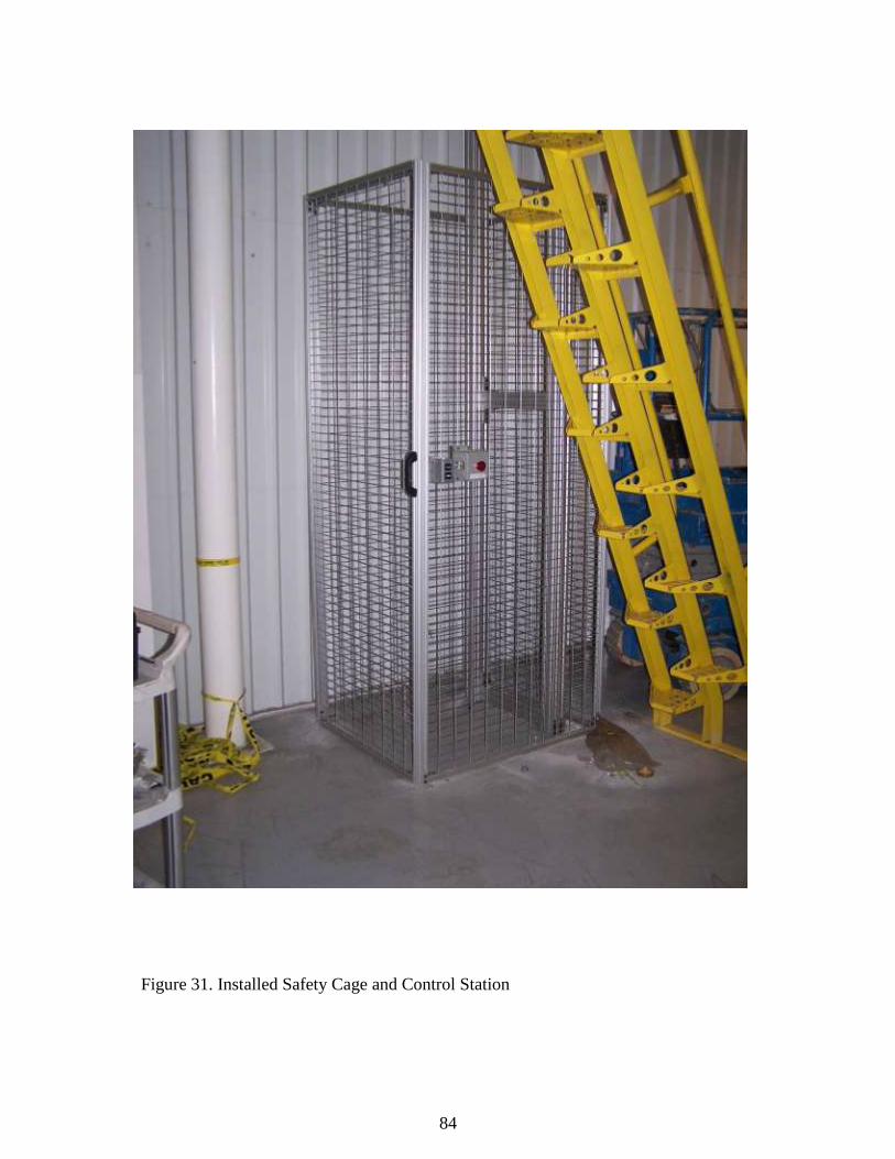
84
Figure 31. Installed Safety Cage and Control Station

85
Figure 32. On Site Testing and Chain Tube

86
Figure 33. On Site Testing 2
Figure 34. On Site Testing 3
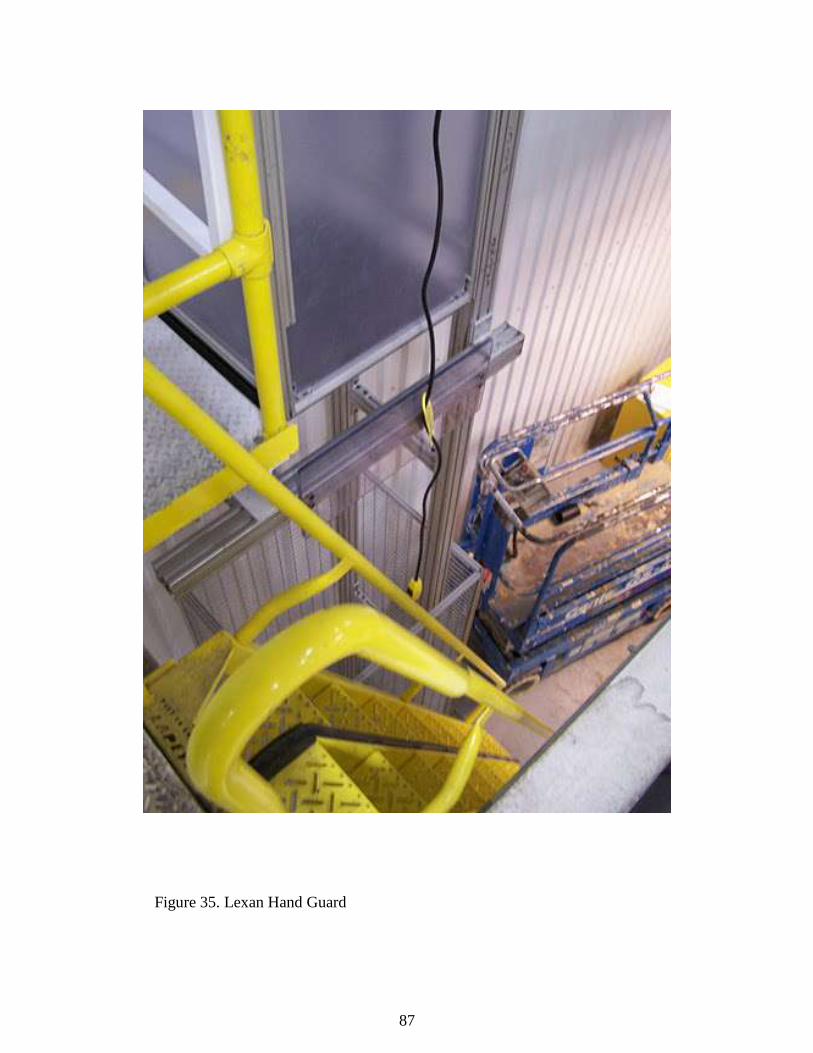
87
Figure 35. Lexan Hand Guard

88
Figure 36. Mezzanine Control Box with Triple Contact Relays
Figure 37. Safety Cage Control Station
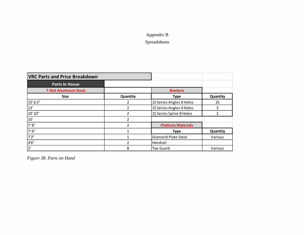
Appendix B
Spreadsheets
Parts In House
T-Slot Aluminum Stock Brackets
Size Quantity Type Quantity
15' 6.5" 2 15 Series Angles 8 Holes 25
13' 2 15 Series Angles 4 Holes 3
10' 10" 2 15 Series Splice 8 Holes 2
10' 2
7' 8" 2 Platform Materials
7' 6" 1 Type Quantity
7'2" 1 Diamond Plate Steel Various
4'6" 2 Handrail
2' 8 Toe Guard Various
VRC Parts and Price Breakdown
Figure 38. Parts on Hand

VRC Frame Parts and Prices
Grainger
Item Part # Price Quantity Total15 Series Roller Wheel 2RCZ4 $25.05 4 $100.20
Dayton Chain Hoist 2GTD2 $940.50 1 $940.50
Chain Bag 3KR20 $46.25 1 $46.25
Aluminum Hinge 5JRL8 $9.40 4 $37.60
1X1 End Caps 5JRG1 $2.82 5 $14.10
3x3 End Caps 2RCR7 $4.95 3 $14.85
$1,153.50
McMaster Carr
Item Part# Price Quantity TotalDouble T Nuts 1.5" 47065T149 $6.76 15 $101.40
Double T Nuts 1" 47065T147 $4.29 25 $107.25
Corner Connectors 47065T51 $4.89 30 $146.70
Rectangle Corner Con. 47065T19 $6.94 0 $0.00
Extended Plates 47065T18 $7.83 6 $46.98
1/2"x3" Stock (8ft.) 47065T109 $72.51 1 $72.51
Magnetic Panel Latch 47065t165 $7.26 2 $14.52
1"X1" Stock (6 ft.) 47065T101 $19.79 7 $138.53
$627.89
Frame Total $1,781.39
Figure 39. Framework Parts

Safety Eq. Parts and Prices
Safety Cage
McMaster Carr
Item Part# Price Quantity Total8' 1x1 47065T101 $26.38 6 $158.28
6' 1X1 47065T101 $19.38 4 $77.52
2' 1x1Angles 47065t175 $4.56 15 $68.40
Magnetic Panel Latch 47065t165 $7.26 2 $14.52
8'x4' Wall Panel 40645t14 $63.47 4 $253.88
$572.60
Electrical
Grainger
Item Part# Price Quantity TotalSocket Relay 11 pins 2XC08 $9.29 2 $18.58
Relay Plug In LED 11pins 3PDT 1YCR6 $19.55 2 $39.10
Enclosure 6x6x4 4KN97 $74.73 1 $74.73
Enclosure Back Panel 6XC20 $4.25 1 $4.25
10 FT.Coiled Power Cord 1TNB8 $23.63 1 $23.63
Raise Lower Control Station 2NO 2XVF9 $84.70 2 $169.40
$329.69
Dynamic Design Solutions
Item Part# Price Quantity Total
Door Switch OMR-D4NS3CF $44.50 3 $133.50
Vertical Mounting Actuator STI-11018-0012 $4.90 3 $14.70
$148.20
Safety &
Electical
Total $1,050.49
Parts Total
Frame $1,781.39
Safety & Electrical $1,050.49
Contractor $1,600.00
Grand Total $4,431.88
VRC Total
Figure 40. Safety, Electrical Parts and Grand Total

Appendix C
Figure 41. Initial Four Post Lifting Structure

Figure 42.3 Dimensional View of Initial Four Post Conveyor Design

Figure 43. Initial Single Post Design

Figure 44. 3 Dimensional Single Post Design

Figure 45. Initial Two-Post Design

Figure 46. 3 Dimensional Two-Post Design

Figure 47. Material Cart

99
Figure 48. Safety Cage

100
Figure 49. Schematic

101
Figure 50. Previous Layout

102
Figure 51. New Layout

103
Figure 52. Space Saver Stair Angles

Appendix D
Calculations
3048 mm
1.5481 mm 1.5481 mm
Copy right© 2010, 80/20® Inc., all rights reserv ed. • 80/20® Inc. • 1701 S 400 E • Columbia City , IN 46725 • Ph: 260-248-8030 • www.8020.net
Length From Left Length From Right
120 In. 120 In. 3048 mm
Deflection X Deflection Y
0.0609 In. 0.0609 In.
0.8253 mm
Deflection X Deflection Y
0.0609 In. 0.0609 In.
1.5481 mm 1.5481 mm
6096 mm 70326.5 N/mm² 139.420878 cm 4̂ 139.420878 cm 4̂
Deflection X Deflection Y
0.0325 In. 0.0325 In.
0.8253 mm
241.3 N/mm²
Length: Modulus Of Elasticity: Moment Of Inertia X: Moment Of Inertia Y:
240 In. 10200000 Lbs. / Sq. In. 3.3496 In. 4̂ 3.3496 In. 4̂
Profile:
3030-S
Load: Yield Strength:
27 Lbs. 35000 Lbs. / Sq. In.
12.25 Kg.
Figure 53. 240IN. T-slot Aluminum Deflection Calculation

105
.
1935.48 mm
0.3964 mm 0.3964 mm
Copy right© 2010, 80/20® Inc., all rights reserv ed. • 80/20® Inc. • 1701 S 400 E • Columbia City , IN 46725 • Ph: 260-248-8030 • www.8020.net
Length From Left Length From Right
76.2 In. 76.2 In. 1935.48 mm
Deflection X Deflection Y
0.0156 In. 0.0156 In.
0.2113 mm
Deflection X Deflection Y
0.0156 In. 0.0156 In.
0.3964 mm 0.3964 mm
3870.96 mm 70326.5 N/mm² 139.420878 cm 4̂ 139.420878 cm 4̂
Deflection X Deflection Y
0.0083 In. 0.0083 In.
0.2113 mm
241.3 N/mm²
Length: Modulus Of Elasticity: Moment Of Inertia X: Moment Of Inertia Y:
152.4 In. 10200000 Lbs. / Sq. In. 3.3496 In. 4̂ 3.3496 In. 4̂
Profile:
3030-S
Load: Yield Strength:
27 Lbs. 35000 Lbs. / Sq. In.
12.25 Kg.
Figure 54. 152.4IN T-slot Aluminum Deflection Calculation

106
1112.52 mm
1.6451 mm 1.6451 mm
Copy right© 2010, 80/20® Inc., all rights reserv ed. • 80/20® Inc. • 1701 S 400 E • Columbia City , IN 46725 • Ph: 260-248-8030 • www.8020.net
Length From Left Length From Right
43.8 In. 43.8 In. 1112.52 mm
Deflection X Deflection Y
0.0648 In. 0.0648 In.
1.9263 mm
Deflection X Deflection Y
0.1865 In. 0.1865 In.
4.7381 mm 4.7381 mm
2225.04 mm 70326.5 N/mm² 139.420878 cm 4̂ 139.420878 cm 4̂
Deflection X Deflection Y
0.0758 In. 0.0758 In.
1.9263 mm
241.3 N/mm²
Length: Modulus Of Elasticity: Moment Of Inertia X: Moment Of Inertia Y:
87.6 In. 10200000 Lbs. / Sq. In. 3.3496 In. 4̂ 3.3496 In. 4̂
Profile:
3030-S
Load: Yield Strength:
27 Lbs. 35000 Lbs. / Sq. In.
12.25 Kg.
Figure 55. 87.6 T-Slot Aluminum Deflection Calculation

107
Beam Fixed at Both Ends. Moment of Inertia of a Solid Rectangle
Cantilevered Beam- Concentrated Load at Free End
P=load
l= length of part
E=modulus of elasticity for steel
i= moment of inertia
P=27lbs
l= 240 inches
E= 29,000,000 psi
i= 3.02
Figure 56. Beam Fixed at Two Ends Deflection Calculation, Full Conveyor Length
Figure 57. Beam Fixed at Two Ends Deflection Calculation, Floor to Mezzanine Distance
P=27lbs
l= 152.4 inches
E=29,000,000 psi
i=3.02
Figure 58. Cantilever Beam Fixed at One End Deflection Calculation, Mezzanine to Top of
Conveyor
P=27lbs
l=87.6 inches
E= 29,000,000 psi
i= 3.02

108
Appendix E
Parts Descriptions
Figure 59. Offset Step Space Saver Stairway Front

109
Figure 60.Offset Step Space Saver Stairway Side
Figure 61.Offset Step Space Saver Stairway Top

110
3030-Smooth is a 3.0" x 3.0" T-slotted aluminum profile made from 6105-T5 aluminum. This profile
has eight open T-slots and smooth surfaces. 3030-Smooth compatible with all 15 Series fasteners and
accessories. Recommended for heavy-duty fixture applications.
Part No. Finish lbs. / Ft. Stock
Length
Moment of
Inertia Area
3030-S Clear
Anodized 3.829
145" or
242"
IX= 3.3496"4
IY= 3.3496"4
3.2896"
2
Figure 62. 3x3 Inch 15 Series T-slot Aluminum Profile Information

111
1010 is a 1.0" x 1.0" T-slotted aluminum profile made from 6105-T5 aluminum. This profile has open
T-slots on all four sides and is compatible with all 10 Series fasteners and accessories.
Part
No. Finish
lbs. /
Ft. Stock Length
Moment of
Inertia Area
1010 Clear
Anodized .5097
97, 145 or 242
In.
IX= .0442"4
IY= .0442"4
.4379"
2
Figure 63. 1x1 Inch 10 Series T-slot Aluminum Profile Information

112
1530 is a 1.5" x 3.0" T-slotted aluminum profile made from 6105-T5 aluminum. This profile has six
open T-slots and is compatible with all 15 Series fasteners and accessories.
Part No. Finish lbs. / Ft. Stock Length Moment of
Inertia Area
1530 Clear
Anodized 2.4209
97, 145 or 242
In.
IX= .4824"4
IY= 1.8042"4
2.0798
"2
Figure 64. 3x 1.5 Inch 15 Series T-slot Aluminum Profile Information

113
Figure 65. 10 Series 4 Hole Angle Bracket
Figure 66. 15 Series 8-Hole Angle Bracket

114
Figure 67. 15 Series 8-Hole Extension Plate
Figure 68. Single T-Nut

115
Figure 69. Double T-Nut
Figure 70. 15 Series Roller

116
VITA
MATTHEW CRUM
Personal Data: Date of Birth: February 28, 1986
Place of Birth: Greeneville, Tennessee
Marital Status: Single
Education: Tennessee Technological University, Cookeville, Tennessee;
Manufacturing and Industrial Technology, B.S. 2008
Minor: Business
East Tennessee State University, Johnson City, Tennessee;
Technology, M.S. 2011
Professional
Experience: Project Engineer Intern, The Vistawall Group, Greeneville, Tennessee,
2007-2008
Manufacturing Engineer, Phoenix Closures, Newport, Tennessee
2010-2011
Graduate Assistant, East Tennessee State University, Johnson City,
Tennessee, 2010-2011
Societies: Society of Manufacturing Engineers (2006-2008)
American Foundry Society (2006-2008)
Tennessee Tech. Manufacturing and Industrial Technology Advisory
Board Student Representative (2007-2008)