the design of a direct reading slip meter - archive
TRANSCRIPT

r% i
UNP/^.


Digitized by the Internet Archive
in 2009 with funding from
CARLI: Consortium of Academic and Research Libraries in Illinois
http://www.archive.org/details/designofdirectreOOzahr
THE DESIGN OF A DIRECT READING»a
SLIP METER ^^
A THESIS
PRESENTED BY
GEORGE J. ZAHROBSKY AND LOUIS S. BLOOM
TO THE
PRESIDENT AND FACULTY
OF
ARMOUR INSTITUTE OF TECHNOLOGYFOR THE DEGREE OF
BACHELOR OF SCIENCEIN
ELECTRICAL ENGINEERING
JUNE 2, 1921
APPROVED
Professor of Electrical Engineering
ILLINOIS INSTITUTE OF TECHNOLOGYPAUL V. GALVIN LIBRARY Dean of Sn^neering Studi7.
36 WEST 33RD STREETCHICAGO, IL 60616 Dean of Cultural Studies

THE PgSI^rlT 0? A DIxSOT REASIII^ SLIPLIBTF^R .•
It is only recently tlx^t the direct reodin?
slip meter ht-s entered our market. Heretofore, in-
accor. t e and peculi; r ueans have been employed in
obtsininp- the slip of an induction motor c.n:, the
prectice of most of these methods has heen conti-
nued for the very reeson tht.t they display un-
common phenomena. The principles , upon v;hioh they,
are "btised'will also he discussed here.
".'hen flip is spoken of, the nuti.her of revolu-
tions per minute Vv'hich the rotor of -n induction
motor l&clrs of heing: equ;-l to that of the revolving
field (synchronous speed of niotor) is meant, ;;nd the
percent slip obviously i^: equ^.l to the ratio of
this slip to the synchronous speed. It m y he de-
termined roughly by obtfininp: the difference between
the measured speed of the machine (using a t..-.c herniate
r
and the synchronous speed as calculated from the fre-
quency and the number of poles. T:is is expressed,
matiiemc: tici-.lly as follo^vs:
Treo. in c voles per sec. x 6JSyn. speed - '—x :
:;or
ilo. of pairs 1 poles
. , _ 1£0 X ?ren
.
'^'^^- ^'P^^^ "-
Ho. of pole s
29828

This method, however, is very unreliable ae it involves
a iimtill difference between two large quantities. For
thiK reason it ic preferable to measure slip directly.
The most common method is tii^ use of stroboscopic
slipmeters. The name "Stroboscopic" is -iven to these
because of the peculiar effect a flickering light pro-
duces on a white disc having black sectors equally
spaced. At a recent demonstration and instructive les-
son on lighting given at the Central '^lectric Company
of C!' icago, it was sio.n that with .a higher intensity
of light a black letter on a •'.hite c/ rd falling rapidly
through an aperture could be recognized, v;hereas , with
a slightly lower intensity hardly any cor.c ption as to
what was on the card could be 'ormed. So in the stro-
boscopic metrod used at the Armour Institute of Tech-
nology (Fig. 1), the lamp is 'connected across one phase
of the three phase systems, thus riving light fluctu-
atinns at a rate equal to the frequency of the ^-ource
of supply. The disc wliieh is fastened to the induction
motor has as many black sectors a.- there are poles on
the motor. In this way if the motor i.- run at syraoh-
ronous speed, the disc would appear to remain stj; tionar;,-;


each time the rotor turns through 160 electrical •
degrees (one pole p'tch) there is one alternation
of the current vrave on" each blac!!: sector hat just
enough time Jr.ring one alternation to occupy the
po;:ition of the preceding sector. Although the
current actuallj goes through zero value, the. ra-
pidity o" the change i~ t:uch that the illumina-
tion ic decreases T-r7 sll-htly bz the -hlte hot
carhon still glovs. "ith the induction motor,
hov7ever, t":e slip vv'iich Is inh-rent, causes the
disc to lose its relative position v.ith respect to
the light •;; ve and the uisc seems to move slowly
backward,
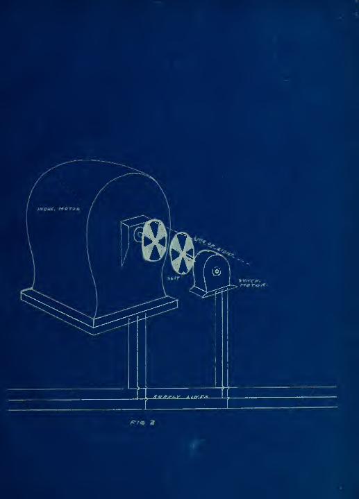
k type of stroboscopic slipmeter, '.vhich eli-
minates th'^ arc lamp, coneii-ts of two discs; one
having bla'^k and 7.hite s ctors symmetrically placed;
the other, long slits. The former is fastened to
the induction motor an' the latter to a siriall syn-
chronous motor, the shaft of which is in line v^ith
that of the induction motor. (?ig. 3) In this
manner on.: ct.n readily see the induction niotor slipping
and acttally count the niunber of sectors which these

openings pass. If the slip "be so great that it is
praotically imposLiTDle to count them, there is a
possibility of overcoming this handicap "by having-
but tv.'O black sectors. In this case the result v;ill
be the slip divided by the number of pairs of poles.
In other words, if we multiply th-^ result obts-ined
in this fashion by the number of p:tirs of poles,
776 h ,.ve the slip.
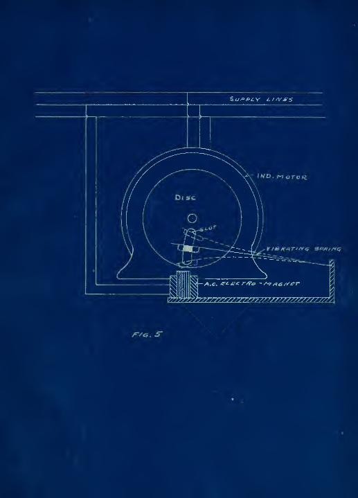
Another type of slipmeter "'hich does not
require an arc lamp was suggested by Professor
Perkins of the University of Tennessei3. (?ig 5)
It Tonsiste of -. disc having a long slender slot,
and alternating current electromagnet, and a steel
armature suspended by a spring. The electromagnet
is connected across one phase of the synchronous^
vibrations. Hence, its name, the vibrating reed
slipmetir. The reed is vie?.'ed through the slct.
Here again if the rotor 7;ere revolving synchronously,
the reed :ould appear to be at the seme point u ith
respect to t're slot, because the observer always
sees it ^t the same part of its cycle. Since the slip
prevents this, the observer always sees it at a slight-


ly different part of its cycle and the result is thut
the raed seems to move uloTly up ahi down. This mo-
tion ie proportional to the tlip as in thj case of
other stroboscopic typet of meters and the numb r of
scillationtT per minute gives the slip.
The time that is required in fretenin;? and
removing the disc to and from motors in the strobo.--
copic methoJ forbids the use of the 1l. tter in places
where motors ar . tested r -gularly. iuOre suitable
devices h. ve been devised to meet this condition.
One device of this kind is the com^r^ut^tor
type slip meter, which Tvas invented by ^ooley. (^'ig.
4) ^cylinder, which is composed of two insulated
parts, actfc as a tort of Goim..ut tor, which has as
many segments as the motor has poles. The position
of th'"^ brushes 1 anl £, is ; uch thai, at the oomiautt-
tor revolv&s , its two parts .re constantly being
shoii; cir-^uited through an ammeter (or ;..0. pol--ired
ball). The othex- t'.''p brushes, 5 and 4, are connected
through a resistance, r, across one phase of the
system.. The current reverses in the ammeter for each
euccestive thort circuit. If tho u.eter weie pressed


agHJnst tht: end of a synchronoufc motor shaft , the
amjneter would give a oonst&nt current reading equal
to the voltage aoros^; on -phase divided by the re-
sistance, r, peed helov/ or shove synchronism
the amrneter inwicates on oscillatin;- current heGau.:e
the irupulses of current through the brushes, 1 and
2, ocr>ur at the same point on che wave. In this way
the ammeter readin^^ is reversed once aach time the
aotor loses half a cycle ana reads its maximum posi-
tive vplue for every loss -of on^: cycle. If, therefore,
the motor loses n cycles per minute, the slip in per-
cent may ho expressed algebraically;
o/o :.lip - -g^
r.'here f is the frequency of the system in cycles per
second.
nother form of com.utator slip meter 7.hich reads
both actual speed and slip is the Bianchi automatic
slipmeter, (?i> 6.). Vhile in its principles it is
si;ailar to the Lool.y motor, it ha,, en attachment for
automgcically registerin.? the number of revolutions of
slip. Tl:is is accomplished by sending the impulses
obtainea from one phase of the system through the

electroma^ricit , . ., .ich drives a pulsating motion
to the permanent magnet, r. ThiL, in turn, aotuates
a raohe.t - and - pa"'l recording meohi^nism. Thus the
slip is recorded on the dial #1, The part (2) beyond
the comrnutator ib /.. tachometer vhioh givc;f the actual
speed of the motor. The sum of the t-^'o readings, 1
and E, gives th^ synchronous speed, and consequently,
the frequency of tl-e supijly.
?0T 10.7 line voltages the electroM^gnet is
throvm ao:iOS£ one phate through a resit:tance, (?., or
(3 ?. ) , ss £hown in accompanying figure. For high
voltages the instrument is connected acros; one phase
through a potential transformer, {I. T.). The
"commutator" i.- composed of one collecting ring and
a number of slender ooiurautatorE , v/hich are insulated
from each othor. Each of the commutators has a different
number of segments so as to enable the manipulator to
read slip directly for motors having any nimbor of poles.
The brush, B. i-;. fixed to the collecting ring , rhile
the brush E is Ci-pable of beii'g moved to any one of
the commutators. An Index plate shows the position
of the movable b.ush for any number of poles.

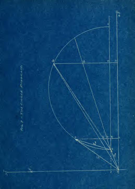
There is also a Rietho' o" o';.t£inin,7 slip from
the circle diagram o" ;n Induotion motor. The dia- .
gram is dra'.'^n fi on dd.t& givin'r relatioac of ourrent
,
voltrge, :nZ pov/er irapat at various load^ including
no loa^, snd loc'.ed rotor. Trom thl£ di'-gran, riore-
over, th« -^o^rirNiete per:'ornic-Gne of t.-e moto^ rncv oe
asoertained. ir.oe slip v: ries at the load for ;
certai;. range, ; ii oxhnr v;- luos aepend on it. Ti:is
can best Tdo made clear by describing a ooomercial
test.
-he m chine is allowed to run '.vithout load hav-
ing rated voltage applied to the terminals. The
ammeter reading , the no load losses, ?;hiGh ooneist
of the core losses, v.'indag , and friction. These
coiabined losses of windage and fiiotion are so sm.Lll
that the v;attmeter indiC£Ltion may be considered to
be due . olely to the 'conductance of the circuit. The
magnetizing current, MO, m£y be considered as having
components in time phase an] time quadrc^ture -vith the
voltage (rig. 6). The magnituted of these componentt
is procured by drawir^g the magnetizing current to
scale at the correct power factor angle, ©, where

is the cj-leulf te- v lue from the formula,
Tuttmeter readin.J-"°^* '^ " Yolt&gs X Current
The proiection of t i o current vector upon the volt-
age vector then gives the in phase current, LI. il,
~'hich is equal to ths core lbs?, windage, and fric-
tion
.
V J rotor is no'v locked and sufficient vol-
tcge is applied to give ahout twice the full load
current in the prims ry. Since the current is prac-
tically proportionil to the voltage at standstill,
the value of the equivalent primary current at the
rated voltage is calculated hy siniple proportion
S - e(_' = 7 ). The value of thiL. vector, MC., is dravi.n
I, la
in a simil-r fashion at its correct po7?er factor
angle. The extremities of these vr-ctors are connect-
ed giving the resultt^nt equivalent secondary current
at standstill, 0;^,. The line OY is drcV.vn to show the
no load losses, which ere constc.nt. T'ais line is on
a diameter of the circle dii^gram. Slaving the diameter
and tio points of a circle, and ', it is an easy
matter to drav;n the circle. The line, 3, is cut at
CJ so that QG and GS are in the same ration as th sec-
ond?;r:: cxnd primary copper losses. It vill he noted,
havever, that the copper loss (wattmeter reading) is

10
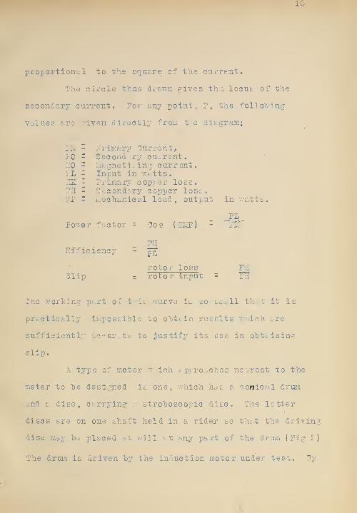
proportion:^! to the square of the cuirent.
The oirole thus dx'&wn gives the locus of the
secondary current. ?or any point, P, the follov^'ing
values are riven directly from tre diagram;
Plvl - Primarj^ Current.10 - Seoondv.ry current,L'iO - Liagneti^'ing current.IL ^ Input in watts.ZK 2 Primary copper loss.?H - Secondr.rj' copper lost,PP - Liechanical load , output in v;atts.
PLPower factor = 'IJos {2I.1P) - ILI
Efficiency - pj^
rotor loss Fli
Slip = rotor input = III
The Vi'orking part of t-iii: curve 1l so small that it is
practically impossible to ohtain results v/'nich are
sufficiently ac'^ur,. te to justify its use in oTDtt.ining
slip.
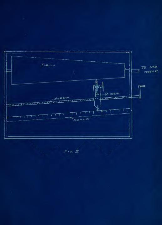
A type of meter "i^ich c prrc^ches nearest to the
meter to he designed is one, ~;hich has a conical drum
and a disc, carrying a stroboscopic disc. The letter
discs ar-3 on one shaft held in a rider so that the driving
disc may be placed at will at any part of the drum (Fig r)
The drum is driven by the induction motor under test. By


setting the disc at a point -i^re it 'aill run in
s^mohronism 7;ita the soui'ie of e-upply (or the li^ht),
the slip rnay "b.^' read directly on a sc.- le as shown.
This method has the disadv. ntages of "being non auto-
matic and using an arc lamp. Its accuracy, however,
is eiccellent ( . hout a.)).
A slip meter which excels i' 11 these "by far is
that suggested by ?.S.LIyard in an artical of the P.evue
GJener;.:le d'Electricite ' (Jc.n. 19, 1920). Tliis is the
one v;hich has hecn decigned c.nd consuiucted by the
authors. Its principle, design, and construction will
no be discussed.
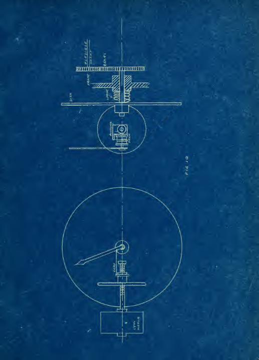
The theory upon v.hich it is based is very
siir.p^e , but the mechi^nical details which are involved
in its design are rather difficult. Piiinarily it con-
sists of tv.'o discs. The larger of these is coniiected
through gears and a flexible shaft to the induction
motor. The smaller disc is free to move on i- threaded
shaft of a synchronous motor. (Fig. 10). As the
flexible shaft is connected to the induction motor, it
revolves the Irger disc, which in return drives the
smaller. In s o doing the latter screws up as it v/ere
to . Gollcir, 7'hich does not permit it to move along the

IE
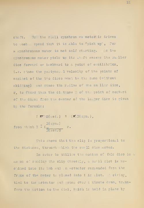
sh&ft. 2Io'-' the s;;i3ll synchronous motor is driven
to such !:. speed that it is able to "pick up'' , For
a synchronous motor is not self sta-rting. As the
synchronous motor picks up its sh, f t screv/s the smaller
disc for>7ard or "backward to a point of eouilibrium,
i.a. since the peripher .1 velocity of the points of
contact of the tvo discs must he the same (without
skid ling) and since the radius of the smvllcr disc,
r, is fixed then the distance ?. of th;: point of contact
of the difcCL; fro::i tlie center of the l&^.jer disc is given
hy the formula:
£ rr ?.!!( act . )- 2rf?M syn. ) ,
_ N(syn.)from v;hich R - { r.
iT( act.O
This sho^vs that the slip is proportional to
the dist nee, through ..'hie h the small disc moves.
In order to utilise thy motion of this disc is a
me.::.ns of reading the slip directly, a small slot is ma-
chined into its huh and .-n actuator suspended from the
frame of the meter is placed into t'lis clot. ', string,
tied to the ^^ctuator and wound over a minute drum, trans-
fers the inotinn to the dial, wiich is held in place "by


"b-- the counter - torque of a sr:.oll sprint.
The bill of mtteri..l is ;. s followc:
(1) ?rame - zn^ohined from 8" pipe length.
(E) Front p.ncl - cast iron- laaohined for glass front.
( ;.. ) Bao]^ panel. - cast iron- Tith hearing for shtift
0^ lai'ge disc.
(4) T'.7o gears - brass- ration 2:1.
(5) r.pecicil brpoket - sheet iron tna soft steel con-
necting gear to flexible shaft.
( 6) dlutch - soft steel.
(7) Flexible sha;ft - "ithout links.
(8) large disc - L.luininiuin.
(9) Spring - conpresLion - to hol.1 Jiscs together.
(10)3nall disc- fiber rivetei to steel hub (tapped).
(iDActuator - soft iron.
(ir)l:i^,l support - soft iron.
(IS) Pointer sh., ft '.-ith small drum.
( 14 )3ynchronous motor(a) rotor - with Ion"- sh^ f t threaded on one
end.(b) 3t- tor - Isininated iron.(c) ""inding - .'27 v.-ire.
(d) Front and bad: panels - cast iron.(e) insulators.(f) Sp3cial brj cket for motor - cast iron.


14
(15) IndactiLnce coil - lt:rninated iron "r.7 -.vire -
two taps n - S50, n - 500.
Ta5 SPLI :' riJAo": 5Y"0I-g.0II0U3 !.:OTOR
It if unnecessary to point out here, in detc.-,il why
a single phase induction or synchronous motor h&s no
starting torque. '2'ae reason for this is that only poly-
phase motors have rotatin-j fields, v/hile the single phase
machines h£ive only a pulsating field. If, however, the
rotor in either type of motor is stt^rted in some other
way, the inertia will c-rry it fiO;u one pole to the
other as the polarity of the field revrses. Only a
little twist on the rotor of a single phase in uction
motor is, requii-ei'i to stert il> , while the synchronous
motor must he brought up to practically synchronous
speed before it will continue to run.
'here there is single phase power and a motor with
•a rotating field is desired, it is possible to use a
split phase aff lir. Such a motor is essentially a two-
phase m -chine. The curi-ent in one phase is mc.de to
differ in time from the current in the other by reducing

15
the voltage in one phase through e reslstonee tmd in
the other through &n inductive or Ccipacity reacttnce.
Of oourt-e, such a motor is inefficient due to the
fact th£tt there is a large resistance loss in one phfcse
and ti-ere is - 1^ rge quadrature current in the other
phase, '.•hich makes a low power factor. The voltage
impressed upon the inotor must necescarily "be smt 11,
Hence this scheme can iDe used onl;' on small induction
motors. The ideal condition would be if one phase
contained pure inductance and no resistance, while the
other phase contained pure resistance and no indi»tance.
Then the currentd ~;ould differ in phase "by 9j degrees.
Since such a condition is impossible of attainment,
the currents will differ by les. then 90 degrees. This
condition is illustrated in Fig. 8. I, is mt^de up
mostly of phase current s-Jid pt.rtly of quadratui'e cur-
rent "'hile la. is made up in the reverse order. The
angle & is less then 90° . it i s actually possible
to get a 90° phase relation by having an inductance
in one branch and a condenser in the other. The
vector diagram {?ig. 9) illustrates that the current
i^ , consists of some inductive, and mostly cbndensive


ib
und resistance current, ^liil e I^ is composed of re-
Bistame and inductive current. Tais arrangement-
ho'vever , is impractio:,.! , for the cap^.city required
for low frequencies is excessive end the cost of
a condenser of this cup-ecity would ni-.ke it prohilDi-
tive. The discussion has "been of an Induction mo-
tor, hut it is e:^sy to see that the principle can
he epplied to a synchronous motor.
In designing the little synchronous motor
fOi the slipmeter much of the work was experiir^ental,
as no such motors are on the Ciarked, and no data
ctn he ohti-ined for its design, "'e nade the sti.tor
of liciinated iron, which has eight polar projections
on it. The '.rinding per pole for each phase was made
to cover two projections, thus fairing four poles per
phase. ooth windings were displitced by ore projection.
In other v/ords there was a space difference of 90
electrical degrees. The rotor ;vas made of ordi-
naiy machine steel, in '.7hich four slots were milled
out to produce polar projections. These were net


magnetized; we made .n attempt to huve the motor
start by its Ovvn power, anJ in so doing put on the
rotor an ..inortiEsear winding, tto ich would -five
the rotor a starting torque and hrin^^ i t up to
alj/.ost synohi'onous speed. The rotor, not being
permanently magneti^^ed, vould then h&ve in.-uced in
it e current » whioh v'ould set up a field to react
with the rott:ting field to produce the torrue, very
little of w'rich is necessary.
.^s stated above, no perlirainary oaloulc tions
could bo made, and the stutor and rotor had to be
made cccording to general proportions and the 'bind-
ings would on, number £7 r.ire was used on the stator.
This has a current o^rrying capacity of tbout 0.5 or
0.6 ampers. Ihere .-re £5 turns per pole and hence
100 turns in all pei phase. The dimensions of the in-
portant parts as follows:
Width of rotor pole face - 0.75"Length of rotor - 1.5"Length of air gap -
i"
o£
Prom this the in'Juct;. nee , L, is calculated"
. £ n^A^ 10x1
3.2 X^ - 10^ X
I
S'g ^ ^0 X .75 X 1.5 z 0.00575 henries.


Oongidering 25 oyole cuirent a^nd 80 volts , which is
the rating of several of th^; in.uction motors in the
Institute, v;e obtain the synchronous reactance of the
motor per phe.se , X.
1 - zrrfL
;: =27rxr.5 x 00.00575 - 0.9 ohm
The resistr^nce per phase is 2.5 ohrns.
Assuiainyr 0,5 amp>.^rs , the drop across the motor is
0.5 X \| 0.9^+2.5 = 2.55 volts.
In the resistance circuit the current v;ill he cl-.ost
entirely in phase, hence the resist cnce to be added
should be in the neighborhood of 157 ohms. In the
inductive c iiouit we c?-;.n neglect the resistrince of
the motor v;indinp:, enci assume tliat we need an impe-
dance of 160 chums. As the resistance of the induct-
ance coil is not laiown, we may assume about 14 ohms
reactance. T'^is value may be easily varied after the
77inding i£ on by changing the length of the air gup.
The core of the inductance cail is made up of
laminations. The cross section of the sm^^llest fluxI'
carrying portion is /l6" by I-^/q" , ana the
mean length of the core is IZ" . Assuming an air gap
of about 0.01 inch, we have

19
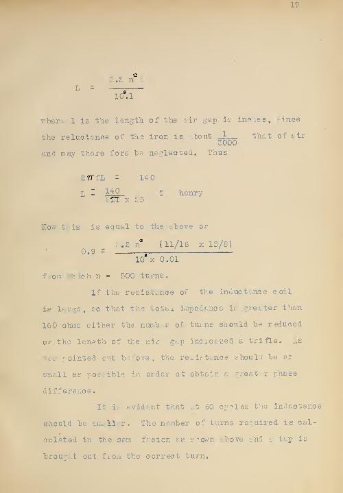
loM
where 1 is the length of the air gap is inohes, ^ince
the reluctf.nae of the iron is .'bout _1 that of air3000
and may there, fore he neglected. Thus
ZTTfL - 140
L -'^^^
- henry
How fr'is is equal to the i.hove or
. .2 n (11/16 X lS/8)0.9 =
g1
10 X 0.01
fx^om >^'hi3h n = 500 turns.
If the resistance of the inductance coil
is large, so that the total impedance ib gre&ter than
160 ohras either the nurrih r of tmns should he reduced
or the length of the air gap increased a trifle. As
7.'&fc- pointed ont bo-''ore , the retibttmce should "be as
t'Tiall as posi-ihle in order ot obtain a greater phase
difference.
It ib' evident that tt 60 cyr>les the inductance
should be smaller. The nmnber of turns required is cal-
culated in the sam fasion as shown --bove and a tap is
brou--:;t out froui the correct turn.

It may seem as thoajh we v/ei-e tr^velin^: froiv: the
cubjeot in discussing these o&loulst ions. It should,
however, he remer.hered that there are no 101131 ished
data on sueh sinall synchronous motors, wl:ich c&nnot
he designed es the Icrger machines , in yvMeh the
fields are either permanently majneti^.ed or excited
hy a direct cuirent. Those machines c&n be deti.j^'ned
roughly as alternators te.'kin^ into considers, ti on
the field flux, current Carrying capacity, phase re-
lation, armature' reaction, etc. xhis has practically
no counter e.m.f. and must be concidered to be a
simple inductance coil , havin-- inductance and resist-
u.nce. The little tynchronous motor was reelly the
big problem in th construction of th- slipmeter.


Dtatyr^
. <cjae>^
r-foToe.

J


i


y^^at^S.
*^Arfe


J


Finiiriiiini imiiimiwiminiii i
wy/j^AfA


''r-y^y"''^y"0

:f|

p-'^' »:•*'
.'-i.'^^-if''^-;^-:»^
