the continuing revolution in automotive electronics -...
TRANSCRIPT

Automotive Electronics Workshop September 9, 2013 Grenoble
The Continuing Revolution in Automotive Electronics
From the Beginning to the Future Presented by Dr. W. R. Bottoms

Automotive Electronics Workshop September 9, 2013 Grenoble Automotive Electronics Workshop September 9, 2013 Grenoble
From The Beginning First automobile 1769 (Cugnot-France)
– Steam power no electronics
First electric automobile 1832 (Anderson- Scotland) – Electric motor, non-rechargeable battery
First internal combustion automobile 1860 (Lenoir-Belgium) – 2-stroke operated on coal gas, only ignition
First electric headlamps 1898 (Columbia Electric Car- Connecticut)
First electric starter 1911 (Kettering [Cadillac]- Michigan)
First automobile electrical system integrating ignition, lighting and electric start 1912-Cadillac-Delco
63 years
28 years
38 years
13 years
1 year

Automotive Electronics Workshop September 9, 2013 Grenoble Automotive Electronics Workshop September 9, 2013 Grenoble
What Drives Automotive Electronics? Issues Independent Of Drive Train
Performance related electronics – Safety (Driver warnings/Bio feedback for sleep alarm, speed alarm, etc.)
– Handling – Navigation – Maintenance
Environmental controls – Temperature – Shading and both internal and external lighting (shades, photochromics, mirror dimming)
Infotainment – Audio – Video – Games – Communications including auto detect for speed limit and other driver information
Security – Communication (both internal and external) – Firewall/virus protection/ Anti-rollover
Haptics – Touch related driver feedback Systems integration Policy
– Safety systems (e.g., airbags, tire pressure sensors) – Driverless vehicles – Black box

Automotive Electronics Workshop September 9, 2013 Grenoble Automotive Electronics Workshop September 9, 2013 Grenoble
What Drives Automotive Electronics? Internal combustion
Performance related electronics – Fuel economy – Emissions – Engine control (including remote startup for
example) Engine maintenance Sound control (Active noise cancelation Communication (both internal and external Policy
– Safety systems (e.g., airbags, tire pressure sensors) – Emissions

Automotive Electronics Workshop September 9, 2013 Grenoble Automotive Electronics Workshop September 9, 2013 Grenoble
What Drives Automotive Electronics? Electric and Hybrid
Performance related electronics – Regenerative breaking – Power control – Battery charging control – Battery condition monitoring – Battery maintenance – For Hybrid add:
• Internal combustion drivers • Add dual drive system coordination
Automotive Electronics Workshop September 9, 2013 Grenoble Automotive Electronics Workshop September 9, 2013 Grenoble
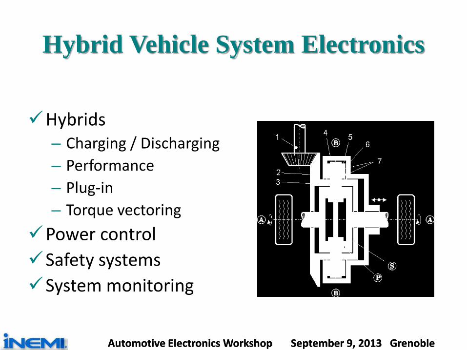
Hybrid Vehicle System Electronics
Hybrids
– Charging / Discharging – Performance – Plug-in – Torque vectoring
Power control Safety systems System monitoring

Automotive Electronics Workshop September 9, 2013 Grenoble
History of Automotive Wireless Communication
Source: Clemson University June 2011

Automotive Electronics Workshop September 9, 2013 Grenoble Automotive Electronics Workshop September 9, 2013 Grenoble
Portable Consumer Products Are Market Drivers Even for Automotive Electronics
The dramatic rise of the mobile device market is expanding automotive electronics to include built-in interfaces for our portable devices. I-pods, tablets and smart phones will all be integrated to provide full portability for these appliances.

Automotive Electronics Workshop September 9, 2013 Grenoble
Components Of Today’s Complex Automotive Electronics
Braking (anti-lock brakes) Collision avoidance systems Communication systems Emissions controls Engine ignition (spark, timing) Entertainment systems Fuel injection Heating/air conditioning Lights, horn, wipers, defrosters … Maintenance
Navigation systems Noise cancellation Safety systems Seat & pedal positions Security systems Steering (steering assist, 4-
wheel steering) Suspension systems Transmission controls

Automotive Electronics Workshop September 9, 2013 Grenoble
Components Of Today’s Complex Automotive Electronics
Braking (anti-lock brakes) Collision avoidance systems Communication systems Emissions controls Engine ignition (spark, timing) Entertainment systems Fuel injection Heating/air conditioning Lights, horn, wipers, defrosters … Maintenance
Navigation systems Noise cancellation Safety systems Seat & pedal positions Security systems Steering (steering assist, 4-wheel
steering) Suspension systems Transmission controls
Current automobiles have more than 130 microprocessors The number of processors expected to double in 5 years. A typical automobile contains about 5 miles of wiring.

Automotive Electronics Workshop September 9, 2013 Grenoble Automotive Electronics Workshop September 9, 2013 Grenoble
These Components Must Be Interconnected
CAN Introduced in 1986 (Controller Area Network)
Serial bus for distributed control system
Twisted-pair media use
Bandwidth up to 1 Mbps
Up to 40 devices.

Automotive Electronics Workshop September 9, 2013 Grenoble Automotive Electronics Workshop September 9, 2013 Grenoble
MOST Introduced in 1998 (Media Oriented Systems Transport)
The MOST bus uses ring topology and synchronous communication for audio, video, voice and data signals. It supports both photonic and electronic data and is used by
almost every car manufacturer in the world.
These Components Must Be Interconnected

Automotive Electronics Workshop September 9, 2013 Grenoble Automotive Electronics Workshop September 9, 2013 Grenoble
The Electronic Content Is Rising
% of Materials cost % of 150mm diameter waferCompact car 15 0.21Luxury Car 28 0.48Hybrid Car 47 0.96Personal Computer - 0.12

Automotive Electronics Workshop September 9, 2013 Grenoble Automotive Electronics Workshop September 9, 2013 Grenoble
The Direction Of Automotive Electronics Is Clear
Electronics and Information Communications Technology are radically transforming the car as a product and an experience. The automobile industry no longer solely operates in the mechanical world. More and more, it is becoming part of the ICT and electronics worlds. High-tech players can seriously disrupt, either directly or indirectly, the automotive landscape as we know it today.
Source: Google, 2012
Almost every car company has acknowledged that future success lies in creating vehicles that are differentiated by electronics and software, rather than just by design and branding. The Automotive industry (like many other industries) is becoming more dependent on the electronics industry.

Automotive Electronics Workshop September 9, 2013 Grenoble Automotive Electronics Workshop September 9, 2013 Grenoble
Ethernet Is Coming to the Automotive Data Network
"We will start seeing automotive Ethernet replacing CAN in eight to 10 years.“
Ali Abaye, Broadcom- August 2013 “When car cameras start handling higher-risk jobs
like lane departure warnings, reading traffic signals, or spotting pedestrians in the crosswalk, carmakers don't want visual information to be sent as compressed video. For such applications, OEMs are beginning to look to Gigabit Ethernet. In 2020, there will be cars equipped with Gigabit Ethernet.”
Peter Hank, NXP Semiconductors August 2013

Automotive Electronics Workshop September 9, 2013 Grenoble Automotive Electronics Workshop September 9, 2013 Grenoble
The Network Will Not Be Just In The Vehicle
Resources in the vehicle will reduce need for infrastructure investment.
Cars will all connected to the network. As they are moving,
they will send real time information that’s collected by all the other cars. There will be no more traffic lights because everybody knows where everybody is.
The data collection from cars sending their position real time will be picked up and processed by a network that can then control position and speed to avoid any collisions.
This network may be the first and perhaps only infrastructure change we’ll see. The networking of vehicles using the existing highway infrastructure will also increase safety and capacity reducing total investment requirement.

Automotive Electronics Workshop September 9, 2013 Grenoble Automotive Electronics Workshop September 9, 2013 Grenoble
What is Available Today Advanced safety technologies to help drivers avoid collisions by:
– improving their vision and awareness of road hazards – Brakes automatically if sensors predict the vehicle is at risk of a
collision. Adaptive Cruise Control and collision avoidance
– Uses radar, ultrasonic sensors and vision sensing detection a vehicle ahead and calculate its distance and relative speed
– Sends a message to the onboard computer to maintain a driver-selected following time/distance.
– Initiates automatic braking and throttle control to maintain selected following distance.
– The driver needs to remain attentive to traffic and road conditions and provide the steering, braking or other inputs necessary to retain control of the vehicle.

Automotive Electronics Workshop September 9, 2013 Grenoble Automotive Electronics Workshop September 9, 2013 Grenoble
What is Available today? Automated parallel parking: All major manufacturers appear to have this
option available. USA Today tested several cars with the following
results: – Land Rover 21.9 seconds – Mercedes Benz 27.4 seconds – Nissan 30.5 seconds – Ford 31 seconds Best driver 16 seconds

Automotive Electronics Workshop September 9, 2013 Grenoble Automotive Electronics Workshop September 9, 2013 Grenoble
The Google Car Has Likely Been To A Neighborhood Near You
It has a driver but the driver does not drive. It has been a legal and liability issue in California.

Automotive Electronics Workshop September 9, 2013 Grenoble Automotive Electronics Workshop September 9, 2013 Grenoble
The Driverless Car Is Coming “Nissan announces plans to release Driverless Cars by 2020”
August 29, 2013
Nissan may be late to market. Recently, Google's self-driving car received a driver’s license from the state of Nevada
Automotive Electronics Workshop September 9, 2013 Grenoble Automotive Electronics Workshop September 9, 2013 Grenoble
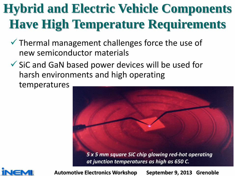
Hybrid and Electric Vehicle Components Have High Temperature Requirements Thermal management challenges force the use of
new semiconductor materials SiC and GaN based power devices will be used for
harsh environments and high operating temperatures
5 x 5 mm square SiC chip glowing red-hot operating at junction temperatures as high as 650 C.

Automotive Electronics Workshop September 9, 2013 Grenoble Automotive Electronics Workshop September 9, 2013 Grenoble
Automotive Electronics Are Unique Requirements: Perform the functions to meet market demand In use reliability of 15 years or more Continuous reduction of cost per function Operation in harsh environments
Difficult Challenges: EMI protection is now a big issue and it will be even more
challenging in the future – Bluetooth and Zigbee are already embedded, broadband
RF is probably next. With higher speed radios and rising electrical energy, EMI will be an increasing challenge
Thermal Management for device, package, modules and sub-systems

Automotive Electronics Workshop September 9, 2013 Grenoble Automotive Electronics Workshop September 9, 2013 Grenoble
Roadmap For Automotive Electronics
4.54.44.23.83.42.8kW/kgPower density1301201101008060Wh/kgEnergy densityBattery for
HEV(high power)
ECU
MotorCapacitor
Battery for BEV(High energy)
Power device
1.51.451.41.31.21kW/kgPower density
600500500500300200A/cm2Drain current density
19681
19664
16949
16936
169-
144-
mm sq.Die size SiSiC/GaN
3SiC/GaN
3SiC/GaN
4SiC/GaN
5SiC/GaN
25MOSFETIGBT
40 MOSFETIGBT
Specific on-resistance at breakdown voltage of 1.2kV
100110130140140130pcsNumber of ECUs
26224022020015050MbpsMedia, information
626262626260kWpower260247234220200170FCapacity of capacitor pack
250240230200150100Wh/kgEnergy density
3023161062W/cm3Inverter power density
150
10
182020
146
10
17.52018
138
10
172016
130
10
162012
125
10
15.52010
135pcsNumber of sensorsSensor
10MbpsPower train, body (CAN→Flex Ray)Network
16.5km/litterMedium car at JC08 modeMileage2014UnitCharacteristicsCategory
15X
13X
- 23%
2.5X

Automotive Electronics Workshop September 9, 2013 Grenoble Automotive Electronics Workshop September 9, 2013 Grenoble
Packaging Requirements For Automotive Electronics
•module self-generating electricity•High speed package•mm-wave devices•Sensor/CPU/actuator integrated module
•Sensors and real-time processing•Monitoring a driver and lanes•Man-machine interface to inform the risk to the driver•Predictive safety mechanism
Safety
•Inverter-embedded motor•Integration
•Integration of MEMS sensor, actuator, interface chip, etc.
Body and security
•Higher data rate•Multiple communication path to outside sources
•Probe-car infrastructure•Traffic information infrastructure
Information/ entertainment
•Integration with network chip•Low impedance•EM immunity design•Higher-pin count packages•Smaller, cheaper EO devices
•X-by-wire; FlexRay (10Mbps)•Longer harness (50km now)•Reducing number of MCUs by networking•Plastic optical fiber
Network
•Lower Ron•Low Rth, cooling system•Management chip built-in cell
•High power, fast switching devices•Intelligent battery management:
Power train -Motor
•High-temperature durable packaging
•ECU-built in engine •Fuel-saving vehicle management
Power train- Combustion
Requirements to packagesTrendCategory

Automotive Electronics Workshop September 9, 2013 Grenoble Automotive Electronics Workshop September 9, 2013 Grenoble
Techniques To Lower Resistance
~1.0mohm~0.5mohm~0.5mohm
Au wireAu wire
DieLead Frame
(Source,Gate)Au Wire
Die pad(Drain)
Lowering Ron → Reduction of Interconnection resistance Reduction of Interconnection resistance
Al ribbon
Cu clip
Thick Cu wire
Cu-Si-Cu stack

Automotive Electronics Workshop September 9, 2013 Grenoble Automotive Electronics Workshop September 9, 2013 Grenoble
Thermal Management for Inverters
Forced air cooling Indirect liquid cooling
Both-sides Indirect liquid cooling Direct liquid cooling

Automotive Electronics Workshop September 9, 2013 Grenoble Automotive Electronics Workshop September 9, 2013 Grenoble
Key Parameters For Automotive Electronics 2012 ITRS
Table AP28 Key Parameters for Automotive ElectronicsYear of Production 2013 2014 2015 2016 2017 2018 2019 2020 2021 2022 2023 2024 2025 2026
Regulation against CO2 emission (g/km)
EU (% to meet 120g/km) CO2 emission (g/km)
75% to 120g/km
80% to 120g/km
100% to 120g/km 120 120 120 120 95
California (g/km) 141 138 132 127 127 127 127 127Japan, JC08 mode (km/litter), equivalent CO2 emission (g/km)
16.3 16.5 16.8km/l130g/km 17 17.3 17.5 17.8 18
Battery performancefor HEV (Power oriented development)
Power density per weight (W/kg) 3600 3800 4000 4200 4300 4400 4450 4500 4550 4600 4650 4700 4750 4800
Energy density per weight (Wh/kg) 90 100 105 110 115 120 125 130 133 135 138 140 142 144
Battery performancefor BEV (Energy oriented development)
Power density per weight (W/kg) 1250 1300 1350 1400 1430 1450 1480 1500 1530 1550 1580 1600 1600 1620
Energy density per weight (Wh/kg) 180 200 220 230 235 240 245 250 255 260 265 270 270 270
Capacitor pack (F) 210 220 227 234 240 247 254 260 260 260 260 260 260 260
Power devices
Inverter power density (W/cm3) 8 10 13 16 20 23 25 30 35 40 45 50 55 60
Specific on-resistance at breakdown voltage of 1.2kV [mOhm*[email protected]] 20 5 5 4 4 3 3 2 2 2 2 2 2 2
Drain current density (A/cm2) 350 500 500 500 500 500 500 600 600 600 700 700 700 700
Max die size of Si-based power device (mm sq.)Max die size of SiC/GaN-based power device (mm sq.)
169-
16936
16936
16949
19649
19664
19664
19681
19681
196100
196100
225121
225121
225121
Motor power (kW) 62 62 62 62 62 62 62 62 62 62 62 62 62 62
Networks
Power train and body (Mbps) 10 10 10 10 10 10 10 10 10 10 10 10 10 10
Media and information (Mbps) 175 200 210 220 230 240 250 262 262 262 262 262 262 262
Number of devices
Sensors (pieces/car) 130 135 134 138 142 146 148 150 150 150 150 150 150 150
ECUs (pieces/car) 140 140 140 130 120 110 100 100 90 80 70 60 50 40
Power devices for automotive electronivccs
Max ambient temperature of power device 125 125 125 125 125 125 125 125 125 125 125 125 125 125
Device
Si-IGBTSi-MOSFET
SiC-MOSFET
GaN-MOSFET
Si-IGBTSi-MOSFET
SiC-MOSFET
GaN-MOSFET
Si-IGBTSi-MOSFET
SiC-MOSFETGaN-
MOSFET
Si-IGBTSi-MOSFET
SiC-MOSFETGaN-
MOSFET
Si-IGBTSi-MOSFET
SiC-MOSFET
GaN-MOSFET
Si-IGBTSi-MOSFET
SiC-MOSFET
GaN-MOSFET
Si-IGBTSi-MOSFET
SiC-MOSFET
GaN-MOSFET
Si-IGBTSi-MOSFET
SiC-MOSFET
GaN-MOSFET
Si-IGBTSi-MOSFET
SiC-MOSFETGaN-
MOSFET
Si-IGBTSi-MOSFET
SiC-MOSFETGaN-
MOSFET
Si-IGBTSi-MOSFET
SiC-MOSFETGaN-
MOSFET
Si-IGBTSi-MOSFET
SiC-MOSFETGaN-
MOSFET
Si-IGBTSi-MOSFET
SiC-MOSFETGaN-
MOSFET
Si-IGBTSi-MOSFET
SiC-MOSFET
GaN-MOSFET
Max junction temperature (degree C) 200 200 220 230 240 250 260 270 270 280 280 280 290 290Rthja required for inverter power density (W/cm3) with regard to Ta of 125deg C (deg C/W/cm3)
9.4 7.5 7.3 6.6 5.8 5.4 5.4 4.8 4.1 3.9 3.4 3.1 3.0 3.0
Max mold temperature (deg C) 200 200 200 200 200 200 200 200 200 200 200 200 200 200
package termical resistance (m Ohm) 0.18 0.16 0.16 0.16 0.16 0.16 0.16 0.16 0.16 0.16 0.16 0.16 0.16 0.16
Logic devices
Temperature attached to engine (degree C) 135 140 145 150 155 155 160 160 165 165 170 170 175 175
Max junction temperature (degree C) 155 160 160 170 175 175 180 180 185 185 190 190 195 195
Bond pad structure OPM OPM OPM OPM OPM OPM OPM OPM OPM OPM OPM OPM OPM OPM
Wire bonding Au/Cu wire Au/Cu wire Au/Cu wire Au/Cu wire Au/Cu wire Au/Cu wire Au/Cu wire Au/Cu wire Au/Cu wire Au/Cu wire Au/Cu wire Au/Cu wire Au/Cu wire Au/Cu wire
SiP structure QFP/SOP/BGA (Side by side+ 3D)
Manufacturable solutions exist, and are being optimized
Manufacturable solutions are known
Interim solutions are known Manufacturable solutions are NOT known
Notes for Table AP 281. Interconnection and cooling will be added for power devices in future revisions
Earliest issues for which we have no know solution are in 2017 and they are control of junction temperature
Only issues of concern through 2015 are Junction temperature control and mold temperature and we think we have known solutions

Automotive Electronics Workshop September 9, 2013 Grenoble Automotive Electronics Workshop September 9, 2013 Grenoble
Key Parameters For Automotive Electronics 2013 ITRS
Table AP28 Key Parameters for Automotive ElectronicsYear of Production 2012 2013 2014 2015 2016 2017 2018 2019 2020 2021 2022 2023 2024 2025 2026
Regulation against CO2 emission (g/km)
EU (% to meet 120g/km) CO2 emission (g/km)
65% to 120g/km
75% to 120g/km
80% to 120g/km
100% to 120g/km 120 120 120 120 95
California (g/km) 145 141 138 132 127 127 127 127 127Japan, JC08 mode (km/litter), equivalent CO2 emission (g/km)
16 16.3 16.5 16.8km/l130g/km 17 17.3 17.5 17.8 18
Battery performancefor HEV (Power oriented development)
Power density per weight (W/kg) 3400 3600 3800 4000 4200 4300 4400 4450 4500 4550 4600 4650 4700 4750 4800
Energy density per weight (Wh/kg) 80 90 100 105 110 115 120 125 130 133 135 138 140 142 144
Battery performancefor BEV (Energy oriented development)
Power density per weight (W/kg) 1200 1250 1300 1350 1400 1430 1450 1480 1500 1530 1550 1580 1600 1600 1620
Energy density per weight (Wh/kg) 150 180 200 220 230 235 240 245 250 255 260 265 270 270 270
Capacitor pack (F) 200 210 220 227 234 240 247 254 260 260 260 260 260 260 260
Power devices
Inverter power density (W/cm3) 5 8 10 13 16 20 23 25 30 35 40 45 50 55 60
Specific on-resistance at breakdown voltage of 1.2kV [mOhm*[email protected]] 25 20 5 5 4 4 3 3 2 2 2 2 2 2 2
Drain current density (A/cm2) 300 350 500 500 500 500 500 500 600 600 600 700 700 700 700
Max die size of Si-based power device (mm sq.)Max die size of SiC/GaN-based power device (mm sq.)
169-
169-
16936
16936
16949
19649
19664
19664
19681
19681
196100
196100
225121
225121
225121
Motor power (kW) 62 62 62 62 62 62 62 62 62 62 62 62 62 62 62
Networks
Power train and body (Mbps) 10 10 10 10 10 10 10 10 10 10 10 10 10 10 10
Media and information (Mbps) 150 175 200 210 220 230 240 250 262 262 262 262 262 262 262
Number of devices
Sensors (pieces/car) 130 130 135 134 138 142 146 148 150 150 150 150 150 150 150
ECUs (pieces/car) 140 140 140 140 130 120 110 100 100 90 80 70 60 50 40
Power devices for automotive electronivccs
Max ambient temperature of power device 125 125 125 125 125 125 125 125 125 125 125 125 125 125 125
Device Si-IGBTSi-MOSFET
Si-IGBTSi-MOSFET
SiC-MOSFET
GaN-MOSFET
Si-IGBTSi-MOSFET
SiC-MOSFET
GaN-MOSFET
Si-IGBTSi-MOSFET
SiC-MOSFETGaN-
MOSFET
Si-IGBTSi-MOSFET
SiC-MOSFETGaN-
MOSFET
Si-IGBTSi-MOSFET
SiC-MOSFET
GaN-MOSFET
Si-IGBTSi-MOSFET
SiC-MOSFET
GaN-MOSFET
Si-IGBTSi-MOSFET
SiC-MOSFET
GaN-MOSFET
Si-IGBTSi-MOSFET
SiC-MOSFET
GaN-MOSFET
Si-IGBTSi-MOSFET
SiC-MOSFETGaN-
MOSFET
Si-IGBTSi-MOSFET
SiC-MOSFETGaN-
MOSFET
Si-IGBTSi-MOSFET
SiC-MOSFETGaN-
MOSFET
Si-IGBTSi-MOSFET
SiC-MOSFETGaN-
MOSFET
Si-IGBTSi-MOSFET
SiC-MOSFETGaN-
MOSFET
Si-IGBTSi-MOSFET
SiC-MOSFET
GaN-MOSFET
Max junction temperature (degree C) 170 200 200 220 230 240 250 260 270 270 280 280 280 290 290Rthja required for inverter power density (W/cm3) with regard to Ta of 125deg C (deg C/W/cm3)
9.0 9.4 7.5 7.3 6.6 5.8 5.4 5.4 4.8 4.1 3.9 3.4 3.1 3.0 3.0
Max mold temperature (deg C) 170 200 200 200 200 200 200 200 200 200 200 200 200 200 200
package termical resistance (m Ohm) 0.18 0.18 0.16 0.16 0.16 0.16 0.16 0.16 0.16 0.16 0.16 0.16 0.16 0.16 0.16
Logic devices
Temperature attached to engine (degree C) 125 135 140 145 150 155 155 160 160 165 165 170 170 175 175
Max junction temperature (degree C) 150 155 160 160 170 175 175 180 180 185 185 190 190 195 195
Bond pad structure OPM OPM OPM OPM OPM OPM OPM OPM OPM OPM OPM OPM OPM OPM OPM
Wire bonding Au/Cu wire Au/Cu wire Au/Cu wire Au/Cu wire Au/Cu wire Au/Cu wire Au/Cu wire Au/Cu wire Au/Cu wire Au/Cu wire Au/Cu wire Au/Cu wire Au/Cu wire Au/Cu wire Au/Cu wire
SiP structure QFP/SOP/BGA (Side by side+ 3D)
Manufacturable solutions exist, and are being optimized
Manufacturable solutions are known
Interim solutions are known Manufacturable solutions are NOT known
Notes for Table AP 281. Interconnection and cooling will be added for power devices in future revisions

Automotive Electronics Workshop September 9, 2013 Grenoble Automotive Electronics Workshop September 9, 2013 Grenoble
Changes in Key Parameters for 2013 ITRS
Year of Production 2012 2013 2014 2015 2016 2017 2018 2019 2020 2021 2022 2023 2024 2025 2026
Device Si-IGBTSi-MOSFET
Si-IGBTSi-MOSFET
SiC-MOSFET
GaN-MOSFET
Si-IGBTSi-MOSFET
SiC-MOSFET
GaN-MOSFET
Si-IGBTSi-MOSFET
SiC-MOSFETGaN-
MOSFET
Si-IGBTSi-MOSFET
SiC-MOSFETGaN-
MOSFET
Si-IGBTSi-MOSFET
SiC-MOSFET
GaN-MOSFET
Si-IGBTSi-MOSFET
SiC-MOSFET
GaN-MOSFET
Si-IGBTSi-MOSFET
SiC-MOSFET
GaN-MOSFET
Si-IGBTSi-MOSFET
SiC-MOSFET
GaN-MOSFET
Si-IGBTSi-MOSFET
SiC-MOSFETGaN-
MOSFET
Si-IGBTSi-MOSFET
SiC-MOSFETGaN-
MOSFET
Si-IGBTSi-MOSFET
SiC-MOSFETGaN-
MOSFET
Si-IGBTSi-MOSFET
SiC-MOSFETGaN-
MOSFET
Si-IGBTSi-MOSFET
SiC-MOSFETGaN-
MOSFET
Si-IGBTSi-MOSFET
SiC-MOSFET
GaN-MOSFET
Max junction temperature (degree C) 170 200 200 220 230 240 250 260 270 270 280 280 280 290 290Rthja required for inverter power density (W/cm3) with regard to Ta of 125deg C (deg C/W/cm3)
9.0 9.4 7.5 7.3 6.6 5.8 5.4 5.4 4.8 4.1 3.9 3.4 3.1 3.0 3.0
Max mold temperature (deg C) 170 200 200 200 200 200 200 200 200 200 200 200 200 200 200
package termical resistance (m Ohm) 0.18 0.18 0.16 0.16 0.16 0.16 0.16 0.16 0.16 0.16 0.16 0.16 0.16 0.16 0.16
Logic devices
Temperature attached to engine (degree C) 125 135 140 145 150 155 155 160 160 165 165 170 170 175 175
Max junction temperature (degree C) 150 155 160 160 170 175 175 180 180 185 185 190 190 195 195
Bond pad structure OPM OPM OPM OPM OPM OPM OPM OPM OPM OPM OPM OPM OPM OPM OPM
Wire bonding Au/Cu wire Au/Cu wire Au/Cu wire Au/Cu wire Au/Cu wire Au/Cu wire Au/Cu wire Au/Cu wire Au/Cu wire Au/Cu wire Au/Cu wire Au/Cu wire Au/Cu wire Au/Cu wire Au/Cu wire
Year of Production 2012 2013 2014 2015
Device Si-IGBTSi-MOSFET
Si-IGBTSi-MOSFET
SiC-MOSFET
GaN-MOSFET
Si-IGBTSi-MOSFET
SiC-MOSFET
GaN-MOSFET
Si-IGBTSi-MOSFET
SiC-MOSFETGaN-
MOSFET
Max junction temperature (degree C) 170 200 200 220Rthja required for inverter power density (W/cm3) with regard to Ta of 125deg C (deg C/W/cm3)
9.0 9.4 7.5 7.3
Max mold temperature (deg C) 170 200 200 200
package termical resistance (m Ohm) 0.18 0.18 0.16 0.16
Logic devices
Temperature attached to engine (degree C) 125 135 140 145
Max junction temperature (degree C) 150 155 160 160
Bond pad structure OPM OPM OPM OPM
Wire bonding Au/Cu wire Au/Cu wire Au/Cu wire Au/Cu wire
Accelerated SiC and GaN
Reduced max junction temperature For power devices
Reduced mold temperature For power devices
Reduced temperature attached to engine and Max junction temperature for logic devices
Accelerated adoption of Cu wire bonds

Automotive Electronics Workshop September 9, 2013 Grenoble Automotive Electronics Workshop September 9, 2013 Grenoble
Thank You for your attention