the consultant shall review
TRANSCRIPT

The Consultant shall review, verify, and confirm the following initial assessment: The Food Production Facility will need a total of 2,900lbs/hr. including 700lbs/hr. for future, i.e. 2 x 700pph + 2 x 400pph + 700pph. Please keep in mind that the actual output of the boiler will be dependent upon operating pressure, feedwater temperature and blowdown. 2 x 50Bhp units will provide you with a redundancy of approximately 50% based upon total needs including future. Initial redundancy will be about 78%, i.e. 1,725/2,200. 1,725 is boiler rating. 2,200 is equal to (2 x 700) + (2 x 400). An additional alternative may be 75Bhp units which are about 10% more money than the 50Bhp units but give you 50% more capacity. The SF75 will also provide a greater redundancy. Documents attached: Standard Specification for SF50 steam generator SF50 specification sheet (brochure) Clayton standard document submittal summary

Technical Specifications
The Next Generation of Clayton Steam Generators
SigmaFire 50 BHPSteam Generator
Available in the following configurations:
•Standard configuration for most installations.•Super Economizer (SE) for increased efficiency.•Low NOx Fiber Metal Burner (FMB) for NOx levels below 12 ppmv.•Step-fired and fully modulating burners.•Fuel Options: Natural Gas, Propane, #2 Fuel Oil, Biogas and Hydrogen.
The SigmaFire:
• SAVES FUEL The unique counter flow design provides higher fuel-to- steam efficiency than traditional boilers.
• IS SAFE FOR PERSONNEL AND EQUIPMENT Inherently safe, the Clayton design eliminates hazardous steam explosions.
• PROVIDES RAPID RESPONSE The Clayton design responds rapidly to sudden or fluctuating load demands.
• STARTS FAST The Clayton design will provide full output from a cold start within five minutes, without thermal stress.
• IS COMPACT AND LIGHTWEIGHT The Clayton design typically occupies one-third of the floor space and weighs 75% less than a traditional boiler.
• ENSURES HIGH QUALITY STEAM Clayton offers a 99.5% quality separator to minimize moisture in the steam.
• OFFERS ADVANCED CONTROLS Digital controllers, PLC’s and a linkage-less servo con- trolled burner management system is available.
• INCLUDES OUTSTANDING SUPPORT Every Steam Generator is backed by Clayton factory direct sales and service plus full service feedwater treatement.

MODEL SF50
BOILER HORSEPOWERHEAT INPUT, BTU/hr Oil
GasNET HEAT OUTPUT, BTU/hrEQUIVALENT OUTPUT (from and at 212°F feedwater and 0 PSIG steam)DESIGN PRESSURE (see note 1)STEAM OPERATING PRESSURE (determined by design pressure)OIL CONSUMPTION at maximum steam output (see note 2)GAS CONSUMPTION at maximum steam output (see note 3)BURNER CONTROLS step fired modulating (see note 4)EFFICIENCY oil-fired efficiency % gas-fired efficiency % ELECTRIC MOTORS, HP Blower Pump Blower Pump design pressure 15-300 psig 3 2 3 2 design pressure 301-500 psig 3 3 3 3ELECTRIC FLA, based on 460 V (see note 5) design pressure 15-300 psig design pressure 301-500 psigGAS SUPPLY REQUIREDAIR SUPPLY REQUIRED (pilot - see note 6)WATER SUPPLY REQUIREDHEATING SURFACEEXHAUST STACK DIAMETER, o.d.APPROXIMATE OVERALL DIMENSIONS length width height WEIGHT installed - wet shipping1) Design pressures are available up to 3000 psig. Consult factory for details.2) Based on No. 2 fuel oil with a High Heat Value (HHV) of 140,600 BTU/Gal.3) Based on Natural Gas with a High Heat Value (HHV) of 1,000 BTU/Ft.³4) On dual fuel units only gas fired is modulating, oil fired is step fired. Switching fuels requires a manual change of burners5) Continuous running. For 575 V multiply by 0.8; for 380 V multiply by 1.1; for 230 V multiply by 2.0; for 208 V multiply by 2.2.6) Pilot air for FMB gas pilot only. Typically 10 seconds per light off.The description and specifications shown were in effect at the time this publication was approved for printing. Clayton Industries, whose policy is one of continuous improvement, reserves the right to discontinue models, or change specifications or design, without notice.
G-SF50 - 4/11
11.88 in. 11.88 in. 11.88 in. 11.88 in.
100% / 50% / Off 100% / 50% / Off 100% / 50% / Off 100% / 50% / Off
2.0 psig 2.0 psig
MODEL SF50-SE-FMBMODEL SF50 MODEL SF-50-SE MODEL SF50-FMB with Low NOx FMB Burner
Standard with Super Economizer with Low NOx FMB Burner and Super Economizer50 50 50 50
2,016,566 1,946,221 NA NA2,041,159 1,969,118 2,066,358 1,969,1181,673,750 1,673,750 1,673,750 1,673,750
1,725 lbs/hr 1,725 lbs/hr 1,725 lbs/hr 1,725 lbs/hr
13 - 450 psig 13 - 450 psig 13 - 450 psig 13 - 450 psig15 - 500 psig 15 - 500 psig 15 - 500 psig 15 - 500 psig
14.3 gph 13.8 gph NA NA
2,041 cfh 1,969 cfh 2,066 cfh 1,969 cfh
N/A85%
4 to 1 Turndown 4 to 1 Turndown5 to 1 Turndown 5 to 1 Turndown
Blower Pump Cooling Blower Pump Cooling5 2 3 5 2 35 3 3 5 3 3
8.2 8.2 15.8 15.89.6 9.6 17.2 17.2
NA NA 5 scfm @ 3 to 150 psig 5 scfm @ 3 to 150 psig2.0 psig 2.0 psig
265 gph 265 gph 265 gph265 gph106 sq.ft. 145 sq.ft. 106 sq.ft. 145 sq.ft.
75 in. 86 in.
63 in. 63 in. 63 in. 63 in.
3,700 lbs 3,930 lbs
66 in. 66 in. 66 in. 66 in.
3,700 lbs 3,930 lbs
75 in. 86 in.
3,842 lbs 4,113 lbs 3,842 lbs 4,113 lbs
83%82%
86%85%
N/A81%

Page 1 of 9
Clayton Standard Documentation Submittals
The following is a list of the standard documentation prepared and submitted by Clayton Industries with a new Steam Generator equipment purchase. As noted, the documentation will vary depending on the scope of Clayton’s supply.
CUSTOMER DRAWINGS:
A set of customer drawings is issued with each new steam generator. This drawing set normally includes a:
Plan installation drawing
Electrical schematic diagram
Wiring diagram
Functional P & ID drawing.
The equipment shown on these drawings will vary depending on whether the steam generator is purchased with or without feed water components, and if the equipment is skid mounted.
Additionally if main loose components are supplied, standard sub-vendor cut sheets for those major components are issued showing dimensions, connection locations and sizing.
Drawing sets can be issued as either generic or job specific. Generic drawings for the model steam generator supplied may show additional equipment and features that are not provided on the specific order. For example, both natural gas and oil fired connections would be shown, although the unit was purchased with gas firing only. Job specific drawings would only show that equipment that was supplied with the order or recommended equipment external to Clayton’s scope of supply.
Job Specific drawing sets can also be provided as certified, for approval, or as-built for additional cost. Note, as-built drawings are issued after the equipment is manufactured.
The following comments explain the type of information included on these drawings:
Plan Installation Drawings
If the steam generator is purchased with either loose feed water components or with feed water components mounted on a separate skid, a plan installation of the steam generator will be issued. If a condensate receiver or feed water skid is purchased, a separate plan installation drawing of the feedwater skid will also be issued. If the steam generator is purchased with a complete generator skid, a plan installation drawing of the complete generator skid only will be issued. The plan installation drawing will include the following information: Top, front and end views Overall and specific dimensions of the unit and all the customer connections A table listing all customer connections with specific sizes, i.e. 1 ½” FPT Reconnection points and sizing for equipment removed for shipping. Overall shipping and operating weights Equipment center of gravity point with dimensions Anchor bolt locations and sizes.

Page 2 of 9
Electrical Schematic Diagram
An electrical schematic diagram will be issued for the main steam generator control panel. If a separate feedwater or condensate receiver skid is supplied with a motor control panel a separate electrical schematic will be issued for the motor control panel.
The electrical schematic diagram shows the following information:
Functional layout of the electrical components included in the panel. Legend key of devices provided. Electrical terminal locations Customer connection points. Motor sizes and voltages Fuse sizes
Electrical Wiring Diagram
An electrical wiring diagram will be supplied for the steam generator panel. This diagram is normally issued in two (or three) sheets.
The first sheet shows the physical layout of the components inside and on the door of the panel. Terminal points are indicated on each component. The legend key is included.
The second (and sometimes third sheet) is supplied showing a wire list and terminal block assignments.
Functional P & I Drawing
The functional P & ID drawing is supplied for all xx4 units. A typical P & ID drawings is supplied for Sigma Fire models. This drawing is issued in two sheets.
The first sheet shows the Fuel & Electrical systems. The second sheet shows the Water / Steam systems.
The following information is indicated on these drawings:
Functional layout of all components and instrumentation required for a complete steam generator system.
Fuel flow and pressure requirements Compressed air flow and pressure requirements Combustion air flow requirements, allowable pressure drops and back pressures. Legend for all components and instruments. Table of all customer connections with sizes and functions Customer reconnection points with sizing Installation notes Boundaries defining Clayton/Customer interface points.
Page 3 of 9
INSTALLATION MANUAL
An installation manual is supplied with each steam generator. This document provides general information to assist in the proper installation of the equipment ranging from basic piping to exhaust stacks, fuel and electrical systems, and optional equipment. The following is a typical table of contents from this helpful manual:
I Introduction II General 2.0 Location recommendations 2.1 Positioning 2.2 Customer Connections – Steam Generator 2.3 Exhaust Stack 2.4 Piping 2.5 Combustion air 2.6 Feed water Treatment 2.7 Electrical 2.8 Net Positive Suction Head (NPSH) 2.9 Flexible Hose connection III Feed Water Systems 3.0 General 3.1 Skid packages 3.2 Customer Connections 3.3 Open system 3.4 Deaerator (DA) 3.5 Semi‐Closed Receiver (SCR) 3.6 Semi‐Closed Receiver Skid 3.7 Head Tank IV Fuel Systems 4.0 General 4.1 Natural Gas 4.2 Oil V Trap Separators 5.0 General 5.1 Operation 5.2 Installation VI Technical Specifications 6.0 General 6.1 Agency Approvals 6.2 Materials of Construction 6.3 Flame Safeguard 6.4 Safety Controls 6.5 Equipment Specifications 6.6 Equipment Layout and Dimensions VII Optional Equipment 7.0 Booster Pumps 7.1 Blow down systems 7.2 Valve Option Kits 7.3 Soot blower Assembly 7.4 Pressure Regulating Valves
Page 4 of 9
FEEDWATER TREATMENT REFERENCE MANUAL
A detailed feedwater treatment reference manual is supplied with each steam generator. This valuable document outlines the proper chemical treatment of a Clayton Steam Generator as well as the correct operating procedures. The following is the table of contents of this document:
Introduction Principle Causes of Water Damage in a Clayton Steam Generator/Fluid Heater Water Basics Water and Its Impurities Principles of Boiler scale and Corrosion control Understanding water flow in a Clayton SG Optimum Water Conditions Unit Operations Softener / Hotwell / Steam Generator / Steam Separator Chemical Treatment Water Quality Requirements Make-up Water / Feed Water / Condensate Coil Guard Technology Additional Chemical Products Product Dosages and Feeding Methods Automatic Chemical Feed Systems Water Testing and Off-line Lay-up conditions Chemical Product selection Water Testing Procedures Start-up Boil out procedures Steam Generator / Fluid Heater Operation System Blow Down Manual / Continuous and Automatic Procedures Shut down Procedures Temporary and Short Term shutdown Wet Shut Down Dry Shut Down Addendums Sizing a Water Softener Coil Guard Technology AWARE Program Chemical Feed System Diagrams Automatic Blow Down System diagram Clayton Chemical part numbers.

Page 5 of 9
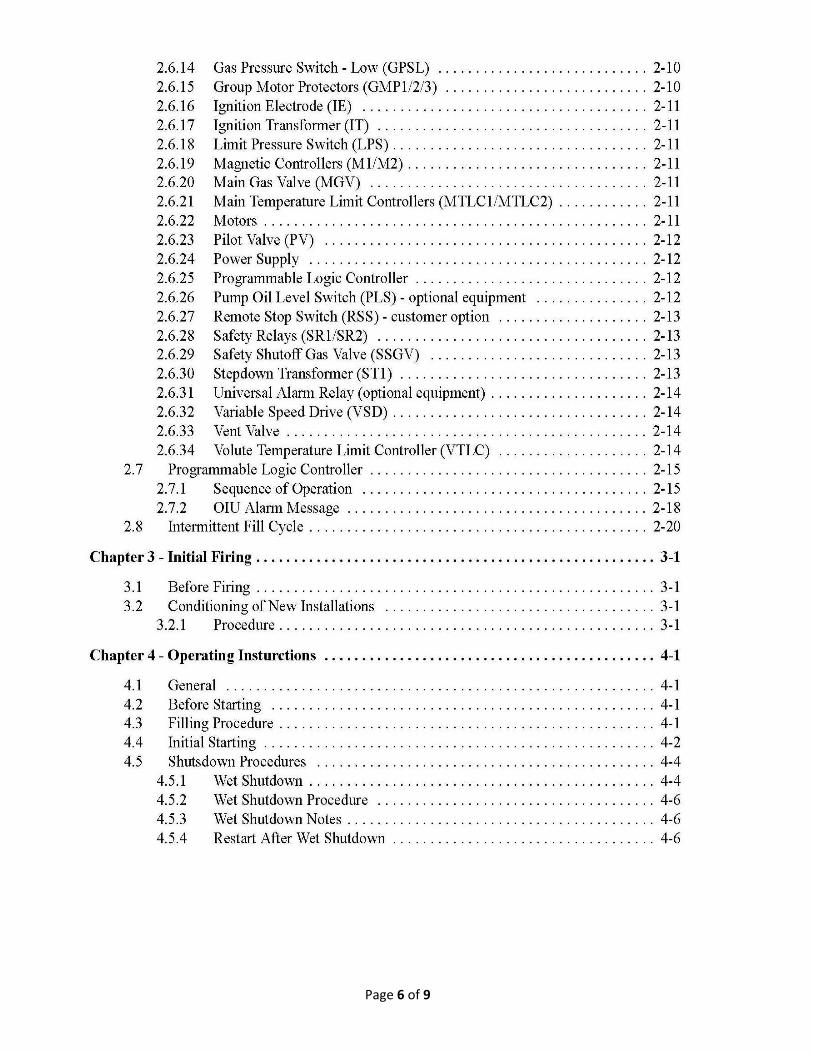
STEAM GENERATOR INSTRUCTION MANUAL (O & M Manual)
A model specific manual containing detailed instructions for the operation and maintenance of a Clayton Steam Generator or Fluid Heater.
Sections include basic descriptions of the major systems, initial firing and normal operation start-up and shutdown procedures, troubleshooting and detailed component maintenance procedures. Supplemental instructions are included for optional equipment along reference tables and charts on the main equipment. A detailed parts catalog is also included with illustrations of the steam generator assemblies.
The following is a typical table of contents found in the O & M Manual:
Page 6 of 9

Page 7 of 9

Page 8 of 9

Page 9 of 9
FACTORY SHOP TEST REPORTS
Each new Clayton Steam Generator is given factory fire test prior to shipment. A written functional test report form is sent with each unit recording the results of these tests.
The report includes the following information:
General: Heating surface, Design pressure, Electrical and Fuel specifications
Component data: Safety valves, motors, controllers, burner description, steam traps, water pump information
Final factory setting for all switches, PLC, burners
Flow rates for fuel flow
Motor FLAs
Shop test performance data including combustion efficiencies, emissions and noise data.
ASME MANUFACTURER’S DATA REPORTS
Forms P-3, 4 and 7 and when required, ASME certified documents as required by ASME power Codes.
PERIODIC MAINTENANCE LOG FORMS
A set of blank periodic maintenance log forms are supplied with each steam generator. These forms can be used by the customer’s maintenance personal to record pertinent operating data on the steam generator performance. It highlights and supplements the recommended maintenance procedures suggested in the O & M Manuals.
ADDITIONAL DOCUMENTS SUPPLIED
Clayton will also issue copies of sub-vendor operating and maintenance manuals such as the Allen Bradley PLC and VSD manuals. This documentation will vary depending on the scope of supply purchased with the Steam Generator.
ELECTRONIC COPIES
It is Clayton’s policy to issue all documentation in an electronic format, preferably Adobe PDF format. Drawings can also be issued in AutoCAD “.dwg” format. Hard paper copies are available for an additional charge per set.

Specification
1. General The steam generator shall be a forced circulation, counterflow mono-watertube configuration with a forced draft burner. The complete steam generator package shall include a monotube heating coil with a waterwall-cooled combustion chamber and integral burner assembly; a motor-driven forced draft blower with centrifugal fan; a motor-driven positive displacement diaphragm-type boiler feedwater pump; fuel train with ignition and flame supervisory controls; separate ASME code stamped steam separator with trap assembly, pressure relief valve(s) and blowdown for dissolved solids control; an integral control panel for automatic and manual control of the steam generator, including continuous monitoring safety annunciators. The steam generator shall be provided with the following safety controls in addition to the burner supervisories: coil low water safety control, auxiliary thermostat low water safety switch, steam pressure limit switch, steam safety relief valves, and feed water pump safety relief valve. All components, except the feedwater pump and motor, shall be mounted on a single structural steel base and shall be factory fire-tested as a complete unit. The feedwater pump and motor shall be assembled on a separate skid. The steam generator must be capable of blowdown while on line without losing header pressure from standard design plant operating pressure and without taking the Steam Generator off line.
2. Performance
2.1 Each steam generator shall be rated at 50 Boiler Horsepower and capable of producing a rated
heat output of 1,673,750 BTU/hour or 1,725 lbs/hour of 0 PSIG saturated steam with 212°F saturated feedwater. The unit shall have a design pressure of 150 psig and an operating pressure of 90 psig in conformance with ASME Power Boiler Code, Section I.
2.2 The primary fuel to be used is Natural Gas and will be supplied to the unit at a pressure of 5
psig. 2.3 No Secondary Fuel
2.4 The steam generator shall be capable of starting from a cold filled state to 100% of rated output
capacity in approximately five minutes. 2.5 The steam generator shall be capable of accepting feedwater with a total dissolved solids (TDS)
concentration of up to 8550 ppm. (Normal Operating range of 3000-6000 ppm). The unit shall operate without surface and bottom blowdown.
2.6 The Steam Generator efficiency, defined as the total heat added to the feedwater divided by the
total heat input of the fuel fired (i.e. net heat output divided by gross heat input based upon higher heating value) shall not be less than 80% when operating across the full modulating range of 20% to 100% of rated load.

3. Component Requirements 3.1 Heating Coil The heating coil shall be designed, built, and stamped per ASME Section I
specifications. The coil shall be monotube design and manufactured from SA178 steel tubing. The assembly shall be stress relieved and shall be hydrostatically tested at 1.5 times the design pressure per ASME guidelines. The heating coil shall be encased in a mild steel jacket, which shall contain all combustion gases. The Jacket shall be insulated to maintain a cool outer skin temperature. The Entire coil assembly shall be covered with a (.048") 18 gauge sheet metal jacket secured in place with pop rivets and/or sheet metal screws. The heat exchanger, coil section shall be complete couterflow design to reduce stack temperature prior to economizer.
Economizer The economizer shall be smooth tube design and integral to the shell of the boiler.
It shall require no additional piping or supports but be supported and integrated into the boiler proper with all interconnecting pipe and connections included.
3.2 Burner The Burner shall be a modulating forced draft design capable of burning the fuels
specified in 2.2 and 2.3, above. The Burner and the associated control system shall be capable of modulating from 20% to 100% of the rated load. The unit will cycle into standby mode when the steam demand falls below 20%.
3.2.1 The burner shall meet the requirements of Industrial Risk Insurers (IRI), Factory
Mutual (FM), and Underwriters Laboratory (UL) and CUL. Burner shall be a packaged design with all components mounted, piped and wired on the steam generator frame.
3.2.2 The Burner safeguard shall be a Seimens LMV 51. 3.2.3 The Burner must meet Current Nox Emissions for the Province of Ontario and be less
than 49ppm. 3.3 Combustion Air Blower Combustion air shall be provided by a centrifugal blower complete
with duct and damper assembly. The Blower shall be connected to an AC, ODP, motor suitable for the service.
3.4 Steam Separator The steam separator shall be designed, built, tested and stamped per ASME
Section I. The unit shall be sized to properly separate steam from water and solids and to provide a minimum of 99.5 % dry steam at the outlet nozzle. The separator shell shall be made from SA53 black pipe. The heads shall be SAE 285 carbon steel. Excess water and solids shall exit the separator through an inverted bucket steam trap for return to the feedwater vessel. The separator shall have openings provided for steam outlet, safety relief valves, coil connection, drain, pressure/ temperature indicators, and an inspectors test cock. The steam separator shall not maintain a water level so as to prevent carry over and be designed for high TDS levels.
3.5 Feedwater Pump The steam generator shall have a diaphragm type, positive displacement
feedwater pump. The pump shall be capable of delivering the required volume of water to the coil. The pump shall be equipped with replaceable diaphragms, and check valve seats and discs.
The pump materials shall be as follows: The crankcase, pump head, and check valve housings
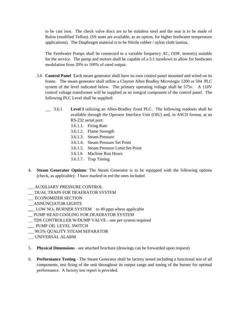
to be cast iron. The check valve discs are to be stainless steel and the seat is to be made of Rulon (modified Teflon). (SS seats are available, as an option, for higher feedwater temperature applications). The Diaphragm material is to be Nitrile rubber / nylon cloth lamina.
The Feedwater Pumps shall be connected to a variable frequency AC, ODP, motor(s) suitable for the service. The pump and motors shall be capable of a 5:1 turndown to allow for feedwater modulation from 20% to 100% of rated output.
3.6 Control Panel Each steam generator shall have its own control panel mounted and wired on its
frame. The steam generator shall utilize a Clayton Allen Bradley Micrologix 1200 or 504 PLC system of the level indicated below. The primary operating voltage shall be 575v. A 110V control voltage transformer will be supplied as an integral component of the control panel. The following PLC Level shall be supplied:
3.6.1 Level I utilizing an Allen-Bradley fixed PLC. The following readouts shall be
available through the Operator Interface Unit (OIU) and, in ASCII format, at an RS-232 serial port: 3.6.1.1. Firing Rate 3.6.1.2. Flame Strength 3.6.1.3. Steam Pressure 3.6.1.4. Steam Pressure Set Point 3.6.1.5. Steam Pressure Limit Set Point 3.6.1.6 Machine Run Hours 3.6.1.7. Trap Timing
4. Steam Generator Options: The Steam Generator is to be equipped with the following options
(check, as applicable): I have marked in red the ones included AUXILIARY PRESSURE CONTROL DUAL TRAPS FOR DEAERATOR SYSTEM ECONOMIZER SECTION ANNUNCIATOR LIGHTS __ LOW NOX BURNER SYSTEM to 49 ppm where applicable PUMP HEAD COOLING FOR DEAERATOR SYSTEM TDS CONTROLLER W/DUMP VALVE - one per system required _ PUMP OIL LEVEL SWITCH 99.5% QUALITY STEAM SEPARATOR UNIVERSAL ALARM 5. Physical Dimensions - see attached brochure (drawings can be forwarded upon request) 6. Performance Testing - The Steam Generator shall be factory tested including a functional test of all
components, test firing of the unit throughout its output range and tuning of the burner for optimal performance. A factory test report is provided.